
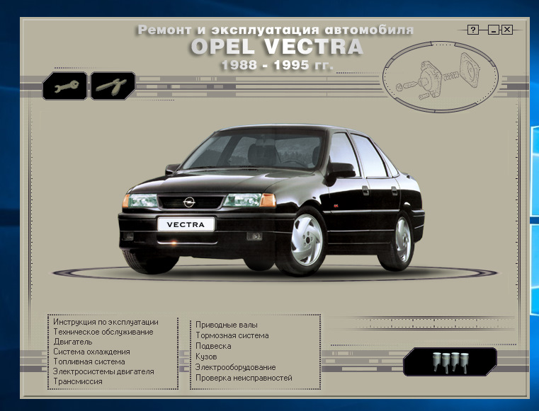
Полное руководство по ремонту и эксплуатации автомобиля Opel Vectra 1988-1995гг. выпуска.
-Полные технические характеристики.
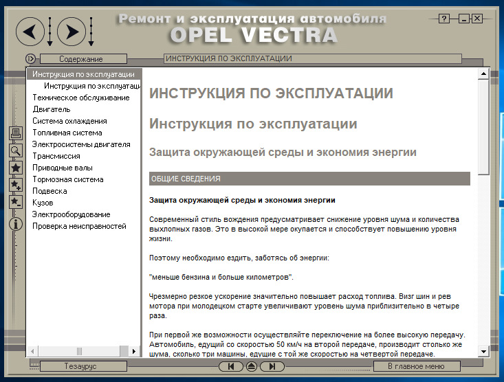
-Инструкция по эксплуатации.
-Тех. обслуживание.Система смазки, система охлаждения, топливная система, тормозная ситема.
-Двигатели, трансмиссия, рулевое управление, ходовая часть, кузов, электрооборудование.
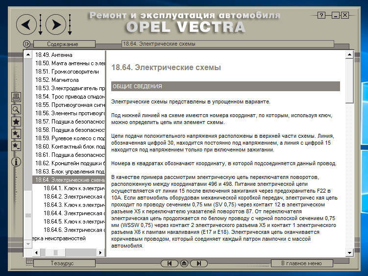
-Электрические схемы. Ключи к схемам.
Download/Скачать
Типы двигателей устанавливаемых на Opel Vectra 1988-1995гг:
Двигатель SOHC – это двигатель с одним распределительным валом, установленным в головке блока цилиндров.
14 NV 1,4 л (1389 см3)
16 SV 1,6 л (1598 см3)
X16 SZ 1,6 л (1598 см3) «Ecotec»
C16 NZ 1,6 л (1598 см3) + катализатор
C16 NZ2 1,6 л (1598 см3) + катализатор
18 SV 1,8 л (1796 см3)
C18 NZ 1,8 л (1796 см3) + катализатор
20 NE 2.0 л (1998 см3)
20 SEH 2.0 л (1998 см3) ранние SRi
C20 NE 2.0 л (1998 см3) + катализатор
Двигатель DOHC – это двигатель с двумя распределительными валами, установленными в головке блока цилиндров. Технические характеристики двигателей DOHC такие же, как и двигателей SOHC 2,0 литра за исключением:
20 XEJ 2.0 л (1998 см3)
C20 XE 2.0 л (1998 см3) + катализатор
X20 XEV 2.0 л (1998 см3) + катализатор, «Ecotec»
Описание:
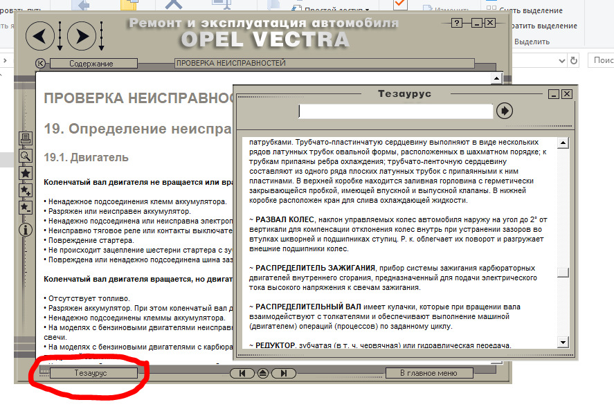
Энциклопедия содержит полную информацию и инструкции по ремонту любой сложности, детальное описание всех узлов, советы по эксплуатации и техобслуживанию, чертежи, таблицы, словарь специальных терминов, проверка различных узлов, помощь при неисправностях и их поиск, различные технические характеристики.
Особенности оболочки:
-Материал четко структурирован
-Понятный, удобный интерфейс
-Расширенная навигация с системой ссылок
-Вариативный поиск
-Большое количество иллюстраций
-Возможность печати с предварительным просмотром документа
-Не требуется установка
Основные разделы:
1. Инструкция по эксплуатации
2. Техническое обслуживание
3. Двигатель
4. Система охлаждения
5. Топливная система
6. Электросистемы двигателя
7. Трансмиссия
8. Приводные валы
9. Тормозная система
10. Подвеска
11. Кузов
12. Электрооборудование
13. Проверка неисправностей
Download/Скачать
- Руководства по ремонту
- Руководство по ремонту Опель Вектра 1988-1995 г.в.
Руководство по ремонту Opel Vectra A / Опель Вектра А
Общая информация об автомобиле.
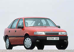
В 1988 году на смену устаревшей Opel Ascona пришёл Opel Vectra. Первое поколение этого ныне очень популярного автомобиля принято обозначать индексом «А». Автомобиль сразу завоевал популярность у водителей и стал бестселлером марки Opel. Создавая Opel Vectra, конструкторы уделили большое внимание прочности кузова. К тому же он обладает отличной антикоррозийной устойчивостью.
Vectra А выпускалась с кузовами четырехдверный седан и пятидверный хэтчбек с поперечно расположенным двигателем. Автомобили предлагались с передним или полным приводом.
Vectra с передними ведущими колесами представляет собой вполне традиционную конструкцию для автомобилей 80-х годов. Передняя подвеска — типа McPherson, задняя — со связанными продольными рычагами. Они жестко соединены поперечной балкой из стального V-образного профиля, которая, работая на кручение, помогает стабилизатору поперечной устойчивости. Чтобы погрузочная поверхность пола багажника была достаточно широкой и низко расположенной, рычаги подвески опущены ниже осей колес, где на них опираются бочкообразные, совсем небольшой высоты витые пружины. Основным преимуществом такой схемы является вместительный багажник.
Гамма силовых агрегатов была представлена: 1,6 л, 75 л.с.; 1,8 л, 88 л.с.; 2,0 л, 115 л.с., а также дизельным двигателем объемом 1,7 л и мощностью 57 л.с.
В большинстве своем Vectra А комплектуются 5-ступенчатыми коробками передач, однако встречаются версии и с 4-ступенчатыми, и с автоматическими.
В конце 1989 года стали выпускаться полноприводные версии «4х4» и «2000 4х4», на которые устанавливались двигатели объемом 1,8 и 2 литра соответственно. Однако отличающиеся устройством трансмиссии и задней подвески, будучи дороже и слегка попрожорливее, полноприводная Vectra не пользовалась большим успехом в Европе.
В 1990 появился хэтчбек Vectra GT. На эту модель ставятся коробка передач со спортивными передаточными числами, спортивная подвеска, спортивный салон и более мощные двигатели.
Осенью 1990 года увидела свет Vectra 2000 16V. Оснащённая мощном 150-сильным шестнадцатиклапанным двигателем.
В 1992 году происходит незначительное обновление модели. С конвейера сошли автомобили с окрашенными в цвет кузова бамперами и зеркалами, изменённой решеткой радиатора и прочими другими чертами, отличающие обновлённые модели от прежних версий.
Появились два новых двигателя: V-образная «шестерка» 2,5 л, полностью соответствующая экологическим нормам Евро II и 2-литровый турбодвигатель.
В 1994 году к существовавшим модификациям — GL, GLS, GT и CD добавились более дорогие: «СD Диамант», «Специал», «Спортив», V6 и люкс-модель CDX.
В ограниченном количестве выпускалась модель «Vectra 4×4 turbo», мощностью 204 л.с.
Всего было выпущено более 2 миллионов экземпляров Vectra А.
1. Защита окружающей среды и экономия энергии
1.0 Защита окружающей среды и экономия энергии
1.2 Ключ
1.3 Рулевое колесо
1.4 Ремень безопасности
1.5 Зеркала заднего вида
1.6 Сиденья
1.7 Замок зажигания
1.8 Органы управления и контрольные приборы
1.9 Контрольные лампы комбинации приборов
1.10 Приборы
1.11 Контрольные лампы
1.12 Двойной информационный дисплей
1.13 Бортовой компьютер
1.14 Элементы кузова
1.15 Безопасность
1.16 Освещение
1.17 Окна, люк
1.18 Отопление и вентиляция
1.19 Кондиционер
1.20 Автоматическая коробка передач
1.21 Указания по вождению
1.22 Заправка
1.23 Катализатор
1.24 Контрольная лампа электронной системы двигателя
1.25 Выхлопная система, выхлопные газы
1.26 Полный привод
1.27 Система ТС (Traction Control)
1.28 Колеса и шины
1.29 Цепи противоскольжения
1.30 Идентификация автомобиля
1.31 Параметры двигателей
1.32 Ходовые параметры
1.33 Основы безопасной эксплуатации автомобиля
1.34. Еженедельные проверки и обслуживание в пути
1.35 Эксплуатационные материалы и жидкости
2. Техническое обслуживание
2.0 Техническое обслуживание
2.2 Периодичность обслуживания
2.3. Техническое обслуживание
3. Двигатель
3.0 ДВИГАТЕЛЬ
3.2 Общая информация
3.3 Система вентиляции картера
3.4 Проверка компрессии
3.5 Ремонтные операции на двигателе, установленном в автомобиле
3.6 Ремонтные операции, требующие снятия двигателя
3.7 Рекомендации по снятию двигателя
3.8. Снятие и установка двигателя без коробки передач
3.9. Снятие и установка двигателя вместе с коробкой передач
3.10 Замена опор двигателя и коробки передач
3.11 Ремонт двигателя
Зубчатый ремень и шкивы (без автоматического механизма натяжения)
3.13 Зубчатый ремень и механизм натяжения (модели 1,4 и 1,6 л кроме С16 NZ2)
3.14 Отверстие в заднем кожухе зубчатого ремня на моделях 1,4 и 1,6 л
3.15 Зубчатый ремень и механизм натяжения (модели С16 NZ2 1,8 и 2,0 л)
3.16 Переднее уплотнительное кольцо распределительного вала
3.17 Заднее уплотнительное кольцо распределительного вала
3.18 Распределительный вал и корпус распределительного вала
Снятие и установка головки блока цилиндров на двигателе в автомобиле
3.20 Снятие и установка головки блока цилиндров на снятом двигателе
3.21. Ремонт головки блока цилиндров
3.22 Очистка и осмотр головки блока цилиндров
3.23 Гидравлические толкатели клапанов
3.24 Маховик
3.25 Замена переднего уплотнительного кольца коленчатого вала
3.26 Замена заднего уплотнительного кольца коленчатого вала
3.27 Масляный поддон
3.28 Масляный насос
3.29 Ремонт масляного насоса
3.30 Снятие и установка поршней и шатунов
3.31 Проверка поршней и шатунов
3.32. Снятие и установка коленчатого вала
3.33 Проверка коленчатого вала
3.34 Осмотр и проверка зазора в коренных и шатунных подшипниках
3.35 Проверка рабочего зазора подшипника
3.36 Проверка блока цилиндров двигателя
3.37 Запуск двигателя после капитального ремонта
4. Ремонт двигателей DOHC
4.0 Ремонт двигателей DOHC
4.2 Общая информация
4.3 Снятие и установка двигателя
4.4 Замена опор силового агрегата
4.5. Зубчатый ремень, шкивы, шкив механизма натяжения и промежуточный шкив
4.6 Зубчатый ремень с автоматическим механизмом натяжения
4.7 Переднее уплотнительное кольцо распределительного вала
4.8 Распределительные валы
4.9 Монтаж головки блока цилиндров на двигателе, установленном в автомобиле
4.10 Монтаж головки блока цилиндров на двигателе, снятом с автомобиля
4.11 Ремонт головки блока цилиндров
4.12 Гидравлические толкатели клапанов
4.13 Замена переднего уплотнительного кольца коленчатого вала
4.14 Масляный поддон
4.15 Масляный насос
4.16 Масляный радиатор
5. Ремонт дизельного двигателя
5.0 Ремонт дизельного двигателя
5.2 Общая информация
5.3 Ремонт, не требующий снятия двигателя
5.4 Проверка компрессии
5.5 Верхняя мертвая точка (ВМТ) поршня первого цилиндра
5.6 Крышка головки блока цилиндров
5.7 Шкив коленчатого вала
5.8 Кожухи зубчатого ремня
5.9 Замена зубчатого ремня
5.10 Проверка и установка фаз газораспределения
5.11. Механизм натяжения зубчатого ремня и шкивы
5.12 Замена уплотнительного кольца распределительного вала
5.13 Проверка и регулировка зазоров клапанов
5.14 Распределительный вал и толкатели
5.15 Головка блока цилиндров
5.16 Масляный поддон
5.17 Масляный насос
5.18 Замена уплотнительного кольца масляного насоса
5.19 Масляный радиатор
5.20. Поршни с шатунами
5.21 Маховик
5.22 Замена уплотнительных колец коленчатого вала
5.23 Замена опор силового агрегата
5.24 Рекомендации по снятию двигателя
5.25 Снятие и установка двигателя
5.26 Ремонт двигателя
5.27 Запуск двигателя после капитального ремонта
6. Система охлаждения
6.0 СИСТЕМА ОХЛАЖДЕНИЯ
6.2 Общая информация
6.3 Антифриз
6.4 Промывка системы охлаждения
6.5 Слив охлаждающей жидкости
6.6 Заполнение системы охлаждения
6.7 Радиатор (модели с механической коробкой передач)
6.8 Радиатор (модели с автоматической коробкой передач)
6.9 Проверка и очистка радиатора
6.10 Термостат
6.11 Проверка работоспособности термостата
6.12 Водяной насос
6.13 Вентилятор радиатора
6.14 Расширительный бачок и датчик уровня охлаждающей жидкости
6.15 Датчик указателя температуры охлаждающей жидкости
6.16 Термодатчик вентилятора радиатора
6.17 Панель управления отопителем
6.18 Радиатор отопителя
6.19 Двигатель вентилятора отопителя
6.20 Сопла вентиляции
7. Топливная система
7.0 ТОПЛИВНАЯ СИСТЕМА
7.2 Общая информация
7.3 Воздушный фильтр
7.4 Блок регулировки температуры поступающего в двигатель воздуха
7.5 Проверка топливного насоса
7.6 Снятие и установка топливного насоса
7.7 Топливный бак
7.8 Датчик уровня топлива
7.9 Сепаратор паров топлива (модели 1,6 и 1,8 л)
7.10 Педаль акселератора
7.11 Трос акселератора
7.12 Карбюратор
7.13 Снятие и установка карбюратора
7.14 Регулировка оборотов холостого хода и содержания СО
7.15 Игла и поплавок
7.16 Вакуумная диафрагма дроссельной заслонки вторичной камеры
7.17 Диафрагма экономайзера
7.18 Ускорительный насос
7.19 Узел воздушной автоматической заслонки
7.20. Вакуумные блоки перемещения воздушной автоматической заслонки
7.21 Фильтр карбюратора
7.22 Регулировка амортизатора дроссельной заслонки на моделях с автоматической коробкой передач
7.23 Датчик положения дроссельной заслонки на моделях с автоматической коробкой передач
7.24 Проверка клапана увеличения оборотов холостого хода
7.25 Электромагнитный клапан холостого хода на моделях 1,8 л
7.26 Впускной коллектор
8. Топливная и выхлопная система моделей с системой впрыска топлива
8.0 Топливная и выхлопная система моделей с системой впрыска топлива
8.2 Общая информация
8.3 Проверка системы впрыска топлива
8.4 Воздушный фильтр
8.5 Воздушная камера
8.6 Блок управления температурой поступающего в двигатель воздуха
8.7 Датчик температуры поступающего в двигатель воздуха на более поздних моделях
8.8 Снятие давления в топливной системе
8.9 Топливный фильтр на моделях с топливным насосом, расположенным вне топливного бака
8.10 Топливный фильтр на моделях с топливным насосом, расположенным внутри топливного бака
8.11 Проверка топливного насоса
8.12 Топливный насос, установленный вне топливного бака
8.13 Топливный насос, установленный в топливном баке
8.14 Замена реле топливного насоса
8.15 Труба топливозаливной горловины
8.16 Топливный бак
8.17 Датчик уровня топлива
8.18 Гаситель колебаний топлива
8.19 Трос акселератора
8.20 Проверка и регулировка топливной смеси на оборотах холостого хода
8.21 Регулятор давления топлива
8.22 Регулятор оборотов холостого хода
8.23 Датчик положения дроссельной заслонки
8.24 Потенциометр положения дроссельной заслонки
8.25 Измеритель потока воздуха
8.26 Измеритель массы потока воздуха
8.27 Ленточный измеритель массы потока воздуха
8.28. Топливные форсунки (кроме Multec)
8.29 Топливная форсунка (система Multec)
8.30 Проверка топливной форсунки (система Multec)
8.31. Корпус дросселя (кроме системы Multec)
8.32 Корпус дросселя (система Multec)
8.33 Шаговый двигатель управления подачей воздуха на оборотах холостого хода
8.34 Потенциометр положения дроссельной заслонки
8.35 Электронное контрольное устройство (ECU)
8.36 Датчик детонации и модуль (модели X16 SZ)
8.37 Датчик детонации (система Simtec)
8.38 Впускной коллектор (двигатель SOHC без Multec)
8.39 Впускной коллектор (двигатель SOHC с Multec)
8.40 Впускной коллектор (модели DOHC)
9. Выхлопная система и система понижения токсичности выхлопных газов
9.0 Выхлопная система и система понижения токсичности выхлопных газов
9.2 Система понижения токсичности выхлопных газов
9.3 Система повторного сжигания отработанных газов (EGR)
9.4 Клапан EGR (модели с системой Multec)
9.5 Клапан EGR (система Simtec)
9.6 Модуль EGR (модели X16 SZ)
9.7 Узел воздушного насоса (система Simtec)
9.8 Клапан отсечки системы уменьшения токсичности
9.9 Выключающий клапан системы уменьшения токсичности
9.10 Трубка и однонаправленный клапан системы уменьшения токсичности
9.11 Катализатор
9.12 Канистра с углем
9.13 Датчик кислорода (модели с катализатором)
9.14 Выпускной коллектор
9.15. Выхлопная система
10. Топливные системы дизельного двигателя
10.0 Топливные системы дизельного двигателя
10.2 Общая информация
10.3 Корпус воздушного фильтра
10.4 Педаль акселератора
10.5 Датчик уровня топлива
10.6 Топливный бак
10.7 Обогреватель топливного фильтра
10.8 Слив воды из топливного фильтра
10.9 Заполнение и прокачка топливной системы
10.10 Проверка и регулировка максимальных оборотов
10.11 Проверка и регулировка оборотов холостого хода
10.12 Электромагнитный клапан остановки двигателя
10.13 Топливный насос высокого давления
10.14 Проверка и регулировка момента впрыска топлива
10.15 Топливные форсунки
10.16 Турбонагнетатель
10.17 Теплообменник
10.18 Впускной коллектор
10.19 Выпускной коллектор
11. Электросистемы двигателя
11.0 ЭЛЕКТРОСИСТЕМЫ ДВИГАТЕЛЯ
11.2 Общая информация
11.3 Система зажигания
11.4 Проверка системы зажигания
11.5 Правила ухода за аккумулятором
11.6 Проверка аккумулятора
11.7 Зарядка аккумулятора
11.8 Аккумулятор
11.9 Система зарядки
11.10 Генератор
11.11 Приводной ремень генератора
11.12 Снятие и установка генератора
11.13 Щетки генератора
11.14 Генератор BOSCH
11.15 Малогабаритный генератор DELCO-REMY
11.16 Система запуска двигателя
11.17 Стартер
11.18 Снятие и установка стартера
11.19 Катушка зажигания
11.20 Крышка и ротор распределителя зажигания
11.21 Распределитель зажигания (модели SOHC)
11.22 Распределитель зажигания (модели DOHC)
11.23. Ремонт распределителя зажигания
11.24 Проверка и регулировка угла опережения зажигания
11.25 Подстройка момента зажигания под используемый сорт топлива
11.26 Электронные модули
11.27 Элементы MSTS-i
11.28 Датчик скорости/положения коленчатого вала (модели 1,8 л)
11.29 Элементы системы Motronic
11.30 Датчик детонации (модели DOHC)
11.31 Модуль DIS
11.32 Датчик фаз распределительного вала (двигатель С20 ХЕ)
11.33 Система предпускового подогрева
11.34 Свечи накаливания
12. Трансмиссия
12.0 Трансмиссия
12.2 Общая информация
12.3 Трос сцепления
12.4 Регулировка троса сцепления
12.5 Педаль сцепления
12.6. Сцепления (двигатель и коробка передач установлены в автомобиле)
12.7 Сцепление (коробка передач снята)
12.8 Выжимной подшипник
13. Механическая коробка передач
13.0 Механическая коробка передач
13.2 Общая информация
13.3 Регулировка тяги механизма выбора передач
13.4 Узел рычага переключения передач
13.5 Тяга механизма выбора передач
13.6 Рычаг переключения передач
13.7 Защитный чехол рычага переключения передач
13.8 Уплотнительные кольца дифференциала
13.9 Уплотнительное кольцо входного вала коробки передач
13.10 Снятие и установка коробки передач
13.11 Ремонт коробки передач
13.12 Привод спидометра
13.13 Выключатель фонарей заднего хода
14. Автоматическая коробка передач
14.0 Автоматическая коробка передач
14.2 Общая информация
14.3 Замена трансмиссионной жидкости
14.4 Регулировка механизма принудительного включения пониженной передачи
14.5 Механизм принудительного включения пониженной передачи
14.6 Выключатель блокировки стартера
14.7 Регулировка троса переключения передач
14.8 Трос переключения передач
14.9 Рычаг селектора
14.10 Центральная консоль
14.11 Выключатели подрежима
14.12 Электронное контрольное устройство (ECU)
14.13 Замена лампы подсветки панели рычага селектора
14.14 Шланги и трубки радиатора охлаждения трансмиссионной жидкости
14.15 Замена уплотнительных колец дифференциала
14.16 Датчик температуры трансмиссионной жидкости
14.17 Датчики скорости вращения входного и выходного валов
14.18 Снятие и установка автоматической коробки передач
15. Приводные валы
15.0 Приводные валы
15.2 Общая информация
15.3. Приводной вал
15.4 Промежуточный вал
15.5 Замена шарниров приводного вала
15.6 Замена чехлов шарниров равных угловых скоростей
16. Тормозная система
16.0 ТОРМОЗНАЯ СИСТЕМА
16.2 Общая информация
16.3 Антиблокировочная система тормозов (ABS)
16.4 Прокачка гидравлической тормозной системы
16.5. Замена передних тормозных колодок
16.6 Замена задних тормозных колодок на дисковых тормозах
16.7. Замена задних тормозных колодок на барабанных тормозах
16.8 Замена тормозных колодок ручного тормоза на задних дисковых тормозах
16.9 Суппорт переднего тормоза
16.10 Суппорт заднего дискового тормоза
16.11 Тормозной диск
16.12 Передний тормозной диск
16.13 Задний тормозной диск на моделях с двигателями SOHC
16.14 Задний тормозной диск на моделях с двигателями DOHC
16.15 Тормозной барабан
16.16 Задний рабочий тормозной цилиндр
16.17 Тормозной щит заднего тормоза
16.18 Защитный кожух переднего тормозного диска
16.19 Главный тормозной цилиндр
16.20 Ремонт главного тормозного цилиндра (модели без ABS)
16.21 Вакуумный усилитель тормозов
16.22 Гидравлический модулятор ABS
16.23 Датчики ABS, установленные на колесах
16.24 Блок управления ABS
16.25 Реле ABS (только система ABS-2Е)
16.26 Клапаны регулировки давления
16.27 Тормозные трубопроводы и шланги
16.28 Регулировка ручного тормоза
16.29. Трос ручного тормоза
16.30 Рычаг ручного тормоза
16.31 Педаль тормоза
17. Подвеска
17.0 ПОДВЕСКА
17.2 Общая информация
17.3 Замена подшипника переднего колеса
17.4 Передняя нижняя рама
17.5 Стойка передней подвески
17.6 Нижний рычаг передней подвески
17.7 Замена втулок нижнего рычага передней подвески
17.8 Шаровой шарнир нижнего рычага передней подвески
17.9 Передний стабилизатор поперечной устойчивости
17.10 Замена втулок переднего стабилизатора поперечной устойчивости
17.11 Регулировка подшипника заднего колеса (модели SOHC)
17.12 Замена подшипника заднего колеса (модели SOHC до 1993 года)
17.13 Замена подшипника ступицы заднего колеса (модели с 1993 года)
17.14 Ступица заднего колеса (модели с двигателем SOHC)
17.15 Задний амортизатор
17.16 Замена резиновых элементов крепления заднего амортизатора
17.17 Пружины задней подвески (модели SOHC)
17.18 Узел продольных рычагов задней подвески (модели с двигателями SOHC)
17.19 Задний стабилизатор поперечной устойчивости
17.20 Замена втулки продольного рычага задней подвески
17.21 Крепежный элемент задней ступицы (модели с двигателями SOHC)
17.22 Проверка системы самовыравнивающейся задней подвески
17.23 Элементы системы управления самовыравнивающийся задней подвески
17.24 Замена подшипника заднего колеса (модели с двигателями DOHC)
17.25 Ступица заднего колеса (модели с двигателями DOHC)
17.26 Узел задней подвески (модели с двигателями DOHC)
17.27 Диагональный рычаг задней подвески (модели с двигателями DOHC)
17.28 Задний стабилизатор поперечной устойчивости
17.29 Рулевое колесо
17.30 Центровка рулевого колеса
17.31 Замена эластичной муфты вала рулевой передачи
17.32 Рулевая колонка
17.33 Ремонт рулевой колонки
17.34 Амортизатор рулевой передачи
17.35. Замена защитных кожухов рулевой передачи
17.36 Удаление воздуха из системы рулевого управления с усилителем
17.37 Насос усилителя рулевого управления
17.38 Пополнительный бачок системы усилителя рулевого управления
17.39 Трубы охлаждения жидкости усилителя рулевого управления
17.40 Наконечники рулевой тяги
17.41 Рулевая тяга
17.42 Углы установки передних колес
18. Кузов
18.0 Кузов
18.2 Общая информация
18.3 Меры безопасности при проведении сварочных работ
18.4 Уход за кузовом
18.5 Ремонт незначительных повреждений кузова
18.6 Ремонт сильных повреждений кузова
18.7 Капот
18.8 Замок капота
18.9 Трос замка капота
18.10 Крышка багажника (модели Седан)
18.11 Замок крышки багажника (модели Седан)
18.12 Цилиндр замка крышки багажника (модели Седан)
18.13 Задняя дверь (модели Хэтчбек)
18.14 Замок задней двери (модели Хэтчбек)
18.15 Цилиндр замка задней двери (модели Хэтчбек)
18.16 Стойки задней двери (модели Хэтчбек)
18.17 Двери
18.18 Обивка двери
18.19 Внутренняя ручка открытия двери
18.20 Внешняя ручка открытия двери
18.21 Цилиндр замка двери
18.22 Замок двери
18.23 Ограничитель открытия двери
18.24 Ветровое и заднее стекла
18.25 Задние треугольные форточки
18.26 Стекло двери
18.27 Стеклоподъемники
18.28 Наружное зеркало заднего вида
18.29 Бамперы
18.30 Решетка радиатора
18.31 Дефлектор ветрового стекла
18.32 Вкладыши арки колеса
18.33 Нижняя защитная пластина (брызговик) двигателя
18.34 Откидная створка топливозаливной горловины топливного бака
18.35. Элементы люка
18.36 Отделка интерьера
18.37. Панели отделки панели приборов
18.38 Центральная консоль
18.39 Потолок
18.40 Сидения (без механизмов натяжения ремней безопасности)
18.41 Ремни безопасности
18.42 Механизм натяжения ремня безопасности
18.43 Переднее сидения с механизмом натяжения ремня безопасности
19. Электрическое оборудование кузова
19.0 Электрическое оборудование кузова
19.2 Общая информация
19.3 Электрические цепи
19.4 Обнаружение неисправной цепи
19.5 Предохранители и реле
19.6 Замок зажигания
19.7 Переключатель освещения и указателей поворотов
19.8 Переключатель стеклоомывателя/стеклоочистителя
19.9 Выключатели на панели приборов
19.10 Переключатель регулировки положения внешнего зеркала
19.11 Переключатель электрического привода люка
19.12 Выключатель освещения салона, установленный в стойке двери
19.13 Выключатель освещения багажного отделения
19.14 Выключатель стоп-сигнала.
19.15 Выключатель контрольной лампы ручного тормоза
19.16 Датчик давления масла
19.17 Подсветка прикуривателя
19.18 Часы
19.19 Переднее сиденье с подогревом
19.20 Комбинация приборов
19.21 Элементы комбинации приборов
19.22 Элементы бортового компьютера
19.23 Элементы системы контроля и управления
19.24 Звуковой сигнал
19.25 Фонарь освещения салона
19.26 Замена лампочек внутреннего освещения
19.27 Фара
19.28 Двигатель корректора света фар
19.29 Регулировка света фар
19.30 Система уменьшения интенсивности света фар
19.31 Передний указатель поворотов
19.32 Боковой повторитель поворотов
19.33 Передняя противотуманная фара
19.34 Задние фонари
19.35 Фонарь подсветки номерного знака
19.36. Замена лампочек внешнего освещения
19.37 Замена щеток стеклоочистителя
19.38 Рычаги стеклоочистителя
19.39 Жиклеры омывателя
19.40 Двигатель и тяги стеклоочистителя
19.41 Двигатель стеклоочистителя задней двери
19.42 Двигатель стеклоочистителя фары
19.43 Бачок стеклоомывателя
19.44 Насос стеклоомывателя
19.45 Однонаправленный клапан омывателя фар
19.46 Элементы стеклоподъемников с электрическим приводом
19.47 Программирование системы управления стеклоподъемниками
19.48 Элементы центральной блокировки дверей
19.49 Антенна
19.50 Мачта антенны с электрическим приводом
19.51 Громкоговорители
19.52 Магнитола
19.53 Электродвигатель привода люка
19.54 Трос привода спидометра
19.55 Противоугонная сигнализация
19.56 Элементы противоугонной сигнализации
19.57 Подушка безопасности
19.58 Подушка безопасности со стороны водителя
19.59 Рулевое колесо с подушкой безопасности
19.60 Контактный блок подушки безопасности
19.61 Подушка безопасности со стороны пассажира
19.62 Кронштейн подушки безопасности со стороны пассажира
19.63 Блок управления подушками безопасности
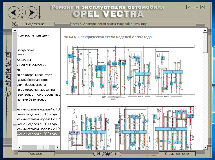
19.64. Электрические схемы
20. Проверка неисправностей
20.0 ПРОВЕРКА НЕИСПРАВНОСТЕЙ
20.2 Система охлаждения
20.3 Топливная и выхлопная системы
20.4 Сцепление
20.5 Механическая коробка передач
20.6 Автоматическая коробка передач
20.7 Приводные валы
20.8 Тормозная система
20.9 Подвеска и рулевое управление
20.10 Электрическое оборудование

Ключ вашего автомобиля
Удалите пластмассовое ушко — у ключа с лампочкой, соответственно, наклейку с номером ключа. Снимите также наклейку с крышки горловины топливного бака. Номер клю

Регулировка рулевого колеса по высоте
Регулировка рулевого колеса по высоте: рулевое колесо может быть установлено в одно из пяти положений. Регулировку рулевого колеса рекомендуется производить тол

Регулировка сидений
Продольное перемещение сиденья Потяните рычаг вверх, затем передвиньте сиденье, отпустить рычаг, зафиксируйте сиденье. Не предпринимайте изменения положения сид

Ремень безопасности
Плавно, без рывков вытяните ремень безопасности из втягивающего устройства, наложите через плечо и защелкните язычок в замке. Не перекручивайте ленту ремня безо

Регулировка зеркал заднего вида
Отрегулируйте внутреннее и наружные зеркала заднего вида. Внутреннее зеркало; отрегулируйте по высоте (шарнир на рамке зеркала). При наклоне внутреннего зеркала

Выключатель зажигания
Выключатель зажигания и стартер бензинового двигателя, предварительное зажигание дизельного двигателя. В = рулевое управление блокировано, зажигание выключено.

Описание приборной панели
1 Переключатель освещения 2 Сопла боковых воздуходувов 3 Переключатель противотуманных фар. Переключатель задних противотуманных фар 4 Переключатель ближнего и

Контрольные лампы в комбинации приборов
Контрольные лампы в левой части Их включение означает: Топливораздаточная колонка — заправиться Сверху слева направо: Стеклоомыватель — долить Уровень масла — н

Механическая коробка передач
• = положение холостого хода 1-4 = передачи с 1-ой по 4-ую 5 = 5-ая передача R = задний ход 5-ая передача переключается вправо с усилием до упора Положение задн

Автоматическая коробка передач
Р = стоянка R = задний ход N = нейтральное положение (холостой ход) Запуск двигателя производится только в положении Р или N. Для включения положений Р или R по

Проверки перед выездом
Перед выездом обязательно проверьте: состояние шин и давление воздуха в них уровень машинного масла и жидкостей в моторном отсеке окна, зеркала и фары наружной

Запуск двигателей
Запуск двигателей 14 NV, 16 SV, 18 SV Рычаг переключения коробки передач установите на холостой ход, выжмите сцепление. При холодном двигателе для включения авт

Установка автомобиля на стоянку
1. Затяните стояночный тормоз. Рычаг переключения передач установите в положение «Р». Выключите фары, так как в противном случае устройство контроля включения ф

Опиание приборов
Тахометр Учитывая показания тахометра вы обеспечиваете более экономный расход топлива. Показания в количестве оборотов в минуту. Черное поле: нормальный расход.

Контрольные лампы
Топливо Загорается, когда стрелка указателя уровня топлива находится в красном секторе. Не продолжайте движения с пустым баком. Система автоматического контроля

Жидкокристаллический индикатор
Контроль функционирования После включении зажигания автоматически включается контроль функционирования (режим контроля), при котором в течение приблизительно 5

Контрольная проверка при включении
При включении зажигания загораются все лампы контрольной проверки. Если все контролируемые функции в порядке, лампы спустя примерно 4 сек. гаснут. Индикация тор

Бортовой компьютер
Бортовой компьютер фирмы Opel информирует о параметрах движения, которые он непрерывно регистрирует и оценивает при помощи электроники. При нажатии кнопки на ди

Безопасность пассажиров
В случае аварии для безопасности пассажиров и прохожих зеркала выходят из держателей. Наружное зеркало: разблокированный корпус зеркала вставьте в фиксаторы. Дл

Эксплуатация ремней безопасности
Пристегивание Плавно вытяните из ролика ремень и наложите через плечо, над бедрами, одновременно следите за тем, чтобы ремень не был перекручен. Язычок ремня за

Внешнее освещение
Регулировка дальности света Дальность света регулируется при включенном ближнем свете в зависимости от нагруженности машины: 0 = занято сиденье водителя 1 = все

Освещение салона
Включается при открывании любой из дверей. После закрытия выключается с задержкой, также и при включенном зажигании. Постоянный режим: включить выключатель осве

Окна дверей
Управляются с помощью поворотного рычага. Электронное управление окнами Два или четыре переключателя на средней консоли; для задних стекол дополнительные клавиш

Сдвижной люк
Для того, чтобы открыть, рукоятку отожмите из углубления, нажмите блокирующую кнопку и поверните рукоятку влево. Люк может также сдвигаться назад. Для этого при

Система отопления и вентиляции
Система смешения воздуха Opel: благодаря смешению холодного и горячего воздуха температура воздуха в салоне может регулироваться и поддерживаться практически на

Устройство и управление кондиционером
Системы вентиляции, отопления и охлаждения образуют функциональный блок, обеспечивающий высокий комфорт в любое время года, при любой погоде и температуре наруж
4A
General
Fuel tank capacity . . . . . . . . . . . . . . . . . . . . . . . . . . . . . . . . . . . . . . . . . . 61.0 litres
Fuel octane rating:
Leaded . . . . . . . . . . . . . . . . . . . . . . . . . . . . . . . . . . . . . . . . . . . . . . . . 98 RON (4-star)
Unleaded . . . . . . . . . . . . . . . . . . . . . . . . . . . . . . . . . . . . . . . . . . . . . . 95 RON (Premium)
Carburettor type (all models) . . . . . . . . . . . . . . . . . . . . . . . . . . . . . . . . . Pierburg 2E3
Air cleaner element
Application:
Round type . . . . . . . . . . . . . . . . . . . . . . . . . . . . . . . . . . . . . . . . . . . . . Champion W103
Square type . . . . . . . . . . . . . . . . . . . . . . . . . . . . . . . . . . . . . . . . . . . . . Champion U512
14 NV engine
Idle speed . . . . . . . . . . . . . . . . . . . . . . . . . . . . . . . . . . . . . . . . . . . . . . . . 925 ± 25 rpm
Idle mixture (CO content) . . . . . . . . . . . . . . . . . . . . . . . . . . . . . . . . . . . . 0.5 to 1.5%
Fast idle speed . . . . . . . . . . . . . . . . . . . . . . . . . . . . . . . . . . . . . . . . . . . . 2200 to 2600 rpm
Choke valve gap . . . . . . . . . . . . . . . . . . . . . . . . . . . . . . . . . . . . . . . . . . . 1.5 to 3.5 mm
Choke pull-down gap:
“Small” . . . . . . . . . . . . . . . . . . . . . . . . . . . . . . . . . . . . . . . . . . . . . . . . 1.7 to 2.1 mm
“Large” . . . . . . . . . . . . . . . . . . . . . . . . . . . . . . . . . . . . . . . . . . . . . . . . 2.5 to 2.9 mm
Idle fuel jet . . . . . . . . . . . . . . . . . . . . . . . . . . . . . . . . . . . . . . . . . . . . . . . 45
Idle air bleed . . . . . . . . . . . . . . . . . . . . . . . . . . . . . . . . . . . . . . . . . . . . . . 130
Primary Secondary
Venturi diameter . . . . . . . . . . . . . . . . . . . . . . . . . . . . . . . . . . . . . . . . . . . 20.0 mm 24.0 mm
Main jet . . . . . . . . . . . . . . . . . . . . . . . . . . . . . . . . . . . . . . . . . . . . . . . . . . X95 X110
Chapter 4 Part A:
Fuel and exhaust systems — carburettor models
Accelerator pump — testing, removal and refitting . . . . . . . . . . . . . . .18
Air cleaner inlet air temperature control — description and testing . . . .4
Air cleaner — removal and refitting . . . . . . . . . . . . . . . . . . . . . . . . . . . .3
Automatic choke unit — removal, refitting and adjustment . . . . . . . . .19
Automatic choke vacuum pull-down units — removal, refitting and
adjustment . . . . . . . . . . . . . . . . . . . . . . . . . . . . . . . . . . . . . . . . . . .20
Carburettor — general . . . . . . . . . . . . . . . . . . . . . . . . . . . . . . . . . . . . .12
Carburettor — removal, overhaul and refitting . . . . . . . . . . . . . . . . . . .13
Carburettor filter — removal and refitting . . . . . . . . . . . . . . . . . . . . . . .21
Fuel level sender unit — removal and refitting . . . . . . . . . . . . . . . . . . . .8
Fuel pump — removal and refitting . . . . . . . . . . . . . . . . . . . . . . . . . . . .6
Fuel pump — testing . . . . . . . . . . . . . . . . . . . . . . . . . . . . . . . . . . . . . . .5
Fuel system — precautions . . . . . . . . . . . . . . . . . . . . . . . . . . . . . . . . . .2
Fuel tank — removal, examination and refitting . . . . . . . . . . . . . . . . . . .7
Fuel vapour separator (1.6 and 1.8 litre models) — removal and
refitting . . . . . . . . . . . . . . . . . . . . . . . . . . . . . . . . . . . . . . . . . . . . . . .9
General description . . . . . . . . . . . . . . . . . . . . . . . . . . . . . . . . . . . . . . .1
Idle cut-off solenoid (1.8 litre models) — description and testing . . . .25
Idle speed and mixture — adjustment . . . . . . . . . . . . . . . . . . . . . . . . .14
Idle speed increase valve — testing . . . . . . . . . . . . . . . . . . . . . . . . . . .24
Inlet manifold — removal and refitting . . . . . . . . . . . . . . . . . . . . . . . . .26
Needle valve and float — removal, inspection and refitting . . . . . . . . .15
Power valve diaphragm — removal and refitting . . . . . . . . . . . . . . . . .17
Secondary throttle valve vacuum diaphragm — testing, removal and
refitting . . . . . . . . . . . . . . . . . . . . . . . . . . . . . . . . . . . . . . . . . . . . . .16
Throttle cable — removal, refitting and adjustment . . . . . . . . . . . . . . .11
Throttle pedal — removal and refitting . . . . . . . . . . . . . . . . . . . . . . . . .10
Throttle position sensor (automatic transmission models) — removal
and refitting . . . . . . . . . . . . . . . . . . . . . . . . . . . . . . . . . . . . . . . . . . .23
Throttle valve dashpot (automatic transmission models) —
adjustment . . . . . . . . . . . . . . . . . . . . . . . . . . . . . . . . . . . . . . . . . . .22
4A•1
Specifications
Contents
Easy, suitable for
novice with little
experience
Fairly easy, suitable
for beginner with
some experience
Fairly difficult,
suitable for competent
DIY mechanic
Difficult, suitable for
experienced DIY
mechanic
Very difficult,
suitable for expert DIY
or professional
Degrees of difficulty
5
4
3
2
1

16 SV engine
Idle speed
Manual transmission . . . . . . . . . . . . . . . . . . . . . . . . . . . . . . . . . . . . . . 925 ± 25 rpm
Automatic transmission . . . . . . . . . . . . . . . . . . . . . . . . . . . . . . . . . . . 825 ± 25 rpm (in ‘park’ or ‘neutral’)
Idle mixture (CO content) . . . . . . . . . . . . . . . . . . . . . . . . . . . . . . . . . . . . 0.5 to 1.5%
Fast idle speed . . . . . . . . . . . . . . . . . . . . . . . . . . . . . . . . . . . . . . . . . . . . 2000 to 2400 rpm
Choke valve gap . . . . . . . . . . . . . . . . . . . . . . . . . . . . . . . . . . . . . . . . . . . 1.5 to 3.5 mm
Choke pull-down gap:
Up to 1990:
“Small” . . . . . . . . . . . . . . . . . . . . . . . . . . . . . . . . . . . . . . . . . . . . . . . . 1.3 to 1.7 mm
“Large” . . . . . . . . . . . . . . . . . . . . . . . . . . . . . . . . . . . . . . . . . . . . . . . . 1.9 to 2.3 mm
From 1990:
“Small” . . . . . . . . . . . . . . . . . . . . . . . . . . . . . . . . . . . . . . . . . . . . . . . . 1.5 to 1.7 mm
“Large” . . . . . . . . . . . . . . . . . . . . . . . . . . . . . . . . . . . . . . . . . . . . . . . . 2.0 to 2.2 mm
Idle fuel jet . . . . . . . . . . . . . . . . . . . . . . . . . . . . . . . . . . . . . . . . . . . . . . . 45
Idle air bleed . . . . . . . . . . . . . . . . . . . . . . . . . . . . . . . . . . . . . . . . . . . . . . 132.5
Primary Secondary
Venturi diameter . . . . . . . . . . . . . . . . . . . . . . . . . . . . . . . . . . . . . . . . . . . 20.0 mm 24.0 mm
Main jet:
Up to 1990 . . . . . . . . . . . . . . . . . . . . . . . . . . . . . . . . . . . . . . . . . . . . . X95 X105
From 1990 . . . . . . . . . . . . . . . . . . . . . . . . . . . . . . . . . . . . . . . . . . . . . . X92.5 X105
18 SV engine
Idle speed . . . . . . . . . . . . . . . . . . . . . . . . . . . . . . . . . . . . . . . . . . . . . . . . 925 ± 25 rpm
Idle mixture (CO content) . . . . . . . . . . . . . . . . . . . . . . . . . . . . . . . . . . . . 0.5 to 1.5%
Fast idle speed . . . . . . . . . . . . . . . . . . . . . . . . . . . . . . . . . . . . . . . . . . . . 1900 to 2300 rpm
Choke valve gap . . . . . . . . . . . . . . . . . . . . . . . . . . . . . . . . . . . . . . . . . . . 1.5 to 3.5 mm
Choke pull-down gap:
“Small” . . . . . . . . . . . . . . . . . . . . . . . . . . . . . . . . . . . . . . . . . . . . . . . . 2.2 ± 0.2 mm
“Large” . . . . . . . . . . . . . . . . . . . . . . . . . . . . . . . . . . . . . . . . . . . . . . . . 3.3 ± 0.2 mm
Idle fuel jet . . . . . . . . . . . . . . . . . . . . . . . . . . . . . . . . . . . . . . . . . . . . . . . 42.5
Idle air bleed . . . . . . . . . . . . . . . . . . . . . . . . . . . . . . . . . . . . . . . . . . . . . . 132.5
Primary Secondary
Main jet . . . . . . . . . . . . . . . . . . . . . . . . . . . . . . . . . . . . . . . . . . . . . . . . . . 107.5 125
Torque wrench settings Nm lbf ft
Exhaust manifold nuts . . . . . . . . . . . . . . . . . . . . . . . . . . . . . . . . . . . . . . 22 16
Exhaust downpipe-to-manifold bolts . . . . . . . . . . . . . . . . . . . . . . . . . . . 25 18
Exhaust fixings except flexible joint bolts . . . . . . . . . . . . . . . . . . . . . . . . 25 18
Exhaust flexible joint bolts . . . . . . . . . . . . . . . . . . . . . . . . . . . . . . . . . . . 12 9
Fuel pump bolts . . . . . . . . . . . . . . . . . . . . . . . . . . . . . . . . . . . . . . . . . . . 18 13
Fuel tank mounting strap bolts . . . . . . . . . . . . . . . . . . . . . . . . . . . . . . . . 20 15
Inlet manifold nuts . . . . . . . . . . . . . . . . . . . . . . . . . . . . . . . . . . . . . . . . . 22 16
1 General description
The fuel system on all carburettor models
comprises a fuel tank, a fuel pump, a vapour
separator (1.6 and 1.8 litre models only), a
downdraught carburettor, and a thermostati-
cally-controlled air cleaner.
The fuel tank is mounted under the rear of
the vehicle, forward of the rear suspension.
The tank is ventilated to the atmosphere, and
has a simple filler pipe and a fuel gauge
sender unit.
The fuel pump is a mechanical diaphragm
type, actuated by a pushrod bearing on the
camshaft.
The fuel vapour separator is used to
stabilise the fuel supply to the carburettor.
Vapour is purged from the carburettor fuel
supply, thus improving hot starting qualities.
The carburettor is a Pierburg 2E3 type, a full
description of which is given in Section 12.
The air cleaner has a wax or vacuum-
controlled air inlet supplying a blend of hot
and cold air to suit the prevailing engine
operating conditions. A fuller description is
given in Section 4.
All engines available within the Cavalier
range can be operated on unleaded petrol —
see Chapter 5.
2 Fuel system — precautions
1 Certain adjustment points in the fuel system
are protected by tamperproof caps, plugs or
seals. In some territories, it is an offence to
drive a vehicle with broken or missing
tamperproof seals. Before disturbing a
tamperproof seal, check that no local or
national laws will be broken by doing so, and
fit a new tamperproof seal after adjustment is
complete, where required by law. Do not
break tamperproof seals on a vehicle that is
still under warranty.
2 When working on fuel system components,
scrupulous cleanliness must be observed,
and care must be taken not to introduce any
foreign matter into fuel lines or components.
Carburettors in particular are delicate
instruments, and care should be taken not to
disturb any components unnecessarily.
Before attempting work on a carburettor,
ensure that the relevant spares are available.
Full overhaul procedures for carburettors have
not been given in this Chapter. Complete
stripdown of a carburettor is unlikely to cure a
fault that is not immediately obvious, without
introducing new problems. If persistent
problems are met, it is recommended that the
advice of a Vauxhall dealer or carburettor
specialist is sought. Most dealers will be able
to provide carburettor re-setting and servicing
facilities, and if necessary it should be
possible to buy a reconditioned carburettor.
3 Refer to Chapter 5, for precautions to be
observed when working on vehicles fitted with
an engine management system.
4A•2 Fuel and exhaust systems — carburettor models
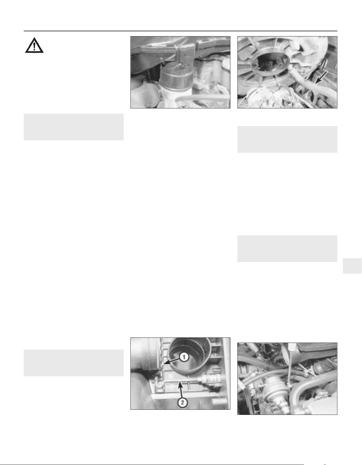
3 Air cleaner — removal and
refitting
2
Removal
1 Remove the air cleaner element, as
described in Chapter 1.
2 Release the crankcase ventilation hose
from the plastic clip on the left-hand side of
the air cleaner body.
3 Disconnect the inlet duct from the hot air
hose on the exhaust manifold (see
illustration), and lift the air cleaner body from
the carburettor.
4 With the body tilted to the rear, disconnect
the crankcase ventilation hose from the stub
on the underside of the body (see
illustration). Where applicable, disconnect
the vacuum hose from the air temperature
control flap thermostat.
5 Remove the seal from under the air cleaner
body.
Refitting
6 Check the hot air hose for condition, and
renew it if necessary.
7 Fit a new air cleaner body-to-carburettor
seal.
8 Connect the crankcase ventilation hose to
the stub on the underside of the body, and
connect the vacuum hose for the air
temperature control flap.
9 Locate the body on the carburettor, and at
the same time locate the inlet duct on the hot
air hose on the exhaust manifold.
10 Engage the crankshaft ventilation hose in
the plastic clip.
11 Refit the air cleaner element, referring to
Chapter 1 if necessary.
4 Air cleaner inlet air
temperature control —
description and testing
3
Description
1 The air cleaner is thermostatically-
controlled, to provide air at the most suitable
temperature for combustion with minimum
exhaust emission levels.
2 The optimum air temperature is achieved
by drawing in cold air from an inlet at the front
of the vehicle, and blending it with hot air
drawn from a shroud on the exhaust manifold.
The proportion of hot and cold air is varied by
the position of a flap valve in the air cleaner
inlet spout, which is controlled by either a
vacuum diaphragm or wax-type unit. The
vacuum diaphragm type is regulated by a heat
sensor located within the air cleaner body
(see illustration).
Testing
3 To check the operation of the air
temperature control, the engine must be cold.
First check the position of the flap valve. On
the vacuum type, remove the air cleaner cover
and check that the flap is open to admit only
cold air from outside the car. Then start the
engine and check that the flap now moves to
admit only hot air from the exhaust manifold.
On the wax type, the flap should already be
positioned to admit only hot air from the
exhaust manifold.
4 Temporarily refit the cover on the vacuum
type.
5 Run the engine until it reaches its normal
operating temperature.
6 On the vacuum type, remove the air cleaner
cover and check that the flap is now
positioned to admit only cold air from outside
the car. In cold weather it should be a mixture
of hot and cold air. Refit the cover after
making the check. On the wax type, use a
mirror to check that the flap is positioned in
the same way as given for the vacuum type.
7 If the flap does not function correctly, the
air cleaner casing must be renewed. Note that
the vacuum type thermostat can be renewed
separately if necessary.
5 Fuel pump — testing
2
Note: Refer to Section 2 before proceeding
1 Disconnect the ignition coil LT lead.
2 Place a clean piece of rag under the pump
outlet, then disconnect the pump outlet hose.
Be prepared for fuel spillage, and take
adequate fire precautions.
3 Have an assistant crank the engine on the
starter. Well-defined spurts of fuel must be
ejected from the pump outlet — if not, the
pump is probably faulty (or the tank is empty).
Dispose of the fuel-soaked rag safely.
4 No spare parts are available for the pump,
and if faulty, the unit must be renewed.
6 Fuel pump — removal and
refitting
3
Note: Refer to Section 2 before proceeding
Removal
1 The fuel pump is located at the rear right-
hand end of the camshaft housing.
2 Disconnect the battery negative lead.
3 Disconnect the fuel hoses from the pump
(see illustration). If necessary, label the
hoses so that they can be reconnected to
their correct locations. Be prepared for fuel
spillage, and take adequate fire precautions.
Plug the open ends of the hoses to prevent
dirt ingress and further fuel spillage.
Fuel and exhaust systems — carburettor models 4A•3
3.4 Disconnecting the crankcase
ventilation hose (arrowed)
6.3 Disconnecting a fuel hose from the
fuel pump — 1.6 litre model
4.2 Air cleaner flap valve operating
mechanism
1 Flap valve 2 Operating rod
3.3 The air cleaner body locates over the
hot air hose
4A
Warning: Many of the
procedures given in this
Chapter involve the
disconnection of fuel pipes and
system components, which may result in
some fuel spillage. Before carrying out
any operation on the fuel system, refer to
the precautions given in the “Safety first!”
Section at the beginning of this manual
and follow them implicitly. Petrol is a
highly dangerous and volatile substance,
and the precautions necessary when
handling it cannot be overstressed.
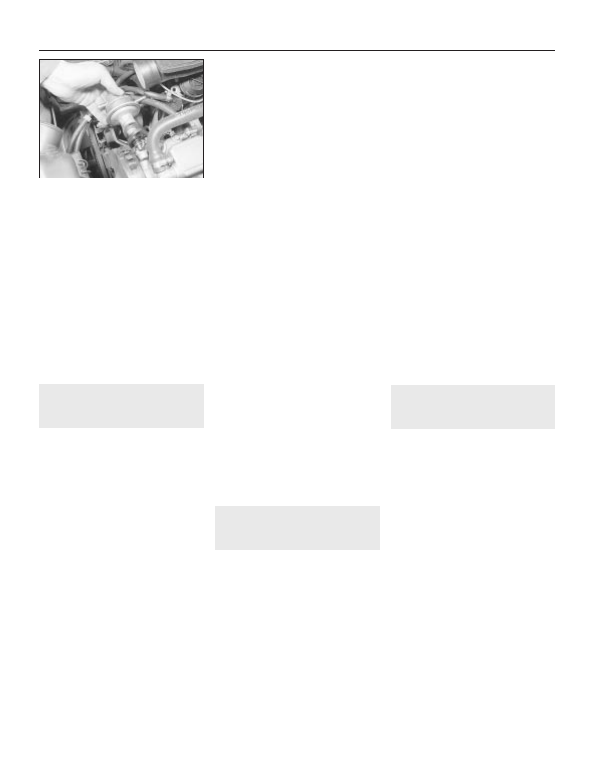
4 Unscrew the two securing bolts, and
withdraw the pump from the camshaft
housing (see illustration).
5 Recover the plastic insulating block.
Refitting
6 Refitting is a reversal of removal, but ensure
that the fuel hoses are reconnected to their
correct locations as noted during removal,
and tighten the securing bolts to the specified
torque.
7 Run the engine and check for leaks on
completion. If leakage is evident, stop the
engine immediately and rectify the problem
without delay. Note that the engine may take
a longer time than usual to start when the
pump has been removed, as the pump refills
with fuel.
7 Fuel tank — removal,
examination and refitting
4
Note: Refer to Section 2 before proceeding
Removal
1 Disconnect the battery negative lead.
2 Siphon out any remaining fuel in the tank
through the filler pipe. Siphon the fuel into a
clean metal container that can be sealed.
3 Chock the front wheels, then jack up the
rear of the vehicle, and support securely on
axle stands (see “Jacking and Vehicle
Support”) placed under the body side
members.
4 Disconnect the exhaust system front
flexible joint. Suspend the front section of the
exhaust system with wire or string from the
underbody.
5 Disconnect the rear section of the exhaust
system from its rubber mountings, and allow it
to rest on the rear suspension torsion beam. It
is advisable to support the rear section of the
exhaust at its front end, with wire or string
from the underbody, to avoid straining the
system.
6 Unclip the handbrake cable from the
bracket on the left-hand fuel tank securing
strap.
7 Disconnect the fuel hoses from the fuel
level sender unit located in the right-hand side
of the fuel tank. Make a note of the hose
positions for use when refitting. Be prepared
for fuel spillage, and take adequate fire
precautions. Plug the open ends of the hoses,
to prevent dirt ingress and further fuel loss.
8 Disconnect the wiring plug from the fuel
level sender unit.
9 Disconnect the filler and vent hoses from
the rear of the fuel tank.
10 Support the weight of the fuel tank on a
jack with an interposed block of wood.
11 Unscrew the securing bolts from the tank
mounting straps, then remove the straps and
lower the tank sufficiently to enable the
disconnection of the remaining vent hose.
12 With the aid of an assistant, withdraw the
tank sideways from the right-hand side of the
vehicle. Note that as the tank is withdrawn,
some residual fuel may be released.
Examination
13 If the tank contains sediment or water, it
may be cleaned out using two or three rinses
with clean fuel. Shake vigorously using
several changes of fuel, but before doing so,
remove the fuel level sender unit, as
described in Section 8. This procedure should
be carried out in a well-ventilated area, and it
is vital to take adequate fire precautions —
refer to the “Safety first!” Section at the
beginning of this manual for further details.
14 Any repairs to the fuel tank should be
carried out by a professional. Do not under
any circumstances attempt to weld or solder a
fuel tank. Removal of all residual fuel vapour
requires several hours of specialist cleaning.
Refitting
15 Refitting is a reversal of removal, ensuring
that all hoses are reconnected to their correct
locations as noted during removal.
16 On completion, fill the fuel tank, then run
the engine and check for leaks. If leakage is
evident, stop the engine immediately and
rectify the problem without delay. Note that
the engine may take a longer time than usual
to start when the fuel tank has been removed,
as the pump refills with fuel.
8 Fuel level sender unit —
removal and refitting
3
Note: Refer to Section 2 before proceeding
Removal
1 Disconnect the battery negative lead.
2 Siphon out any remaining fuel in the tank
through the filler pipe. Siphon the fuel into a
clear metal container that can be sealed.
3 Chock the front wheels, then jack up the rear
of the vehicle, and support securely on axle
stands (see “Jacking and Vehicle Support”)
placed under the body side members.
4 The sender unit is located in the right-hand
side at the fuel tank.
5 Make alignment marks on the sender unit
and the fuel tank, so that the sender unit can
be refitted in its original position.
6 Disconnect the fuel hoses from the sender
unit. Be prepared for fuel spillage, and take
adequate fire precautions. Plug the open ends
of the hoses, to prevent dirt ingress and
further fuel loss.
7 Disconnect the wiring plug from the fuel
level sender unit.
8 To remove the sender unit, engage a flat
piece of metal as a lever between two of the
slots on the sender unit rim, and turn it anti-
clockwise.
9 Withdraw the unit carefully, to avoid
bending the float arm.
10 Recover the sealing ring.
Refitting
11 Refitting is a reversal of removal,
remembering the following points.
12 Examine the condition of the sealing ring,
and renew if necessary.
13 Ensure that the marks made on the
sender unit and fuel tank before removal are
aligned.
14 Ensure that the hoses are reconnected to
their correct locations as noted during
removal.
15 On completion, fill the fuel tank, then run
the engine and check for leaks. Also check
that the fuel gauge reads correctly. If leakage
is evident, stop the engine immediately and
rectify the problem without delay. Note that
the engine may take a longer time than usual
to start when the sender unit has been
removed, as the fuel pump refills with fuel.
9 Fuel vapour separator (1.6
and 1.8 litre models) —
removal and refitting
3
Note: Refer to Section 2 before proceeding
Removal
1 The fuel vapour separator is located on a
bracket attached to the side of the
carburettor.
2 Note the locations of the three fuel hoses,
labelling them if necessary for use when
refitting, then disconnect the hoses from the
vapour separator. Be prepared for fuel
spillage, and take adequate fire precautions.
Plug the open ends of the hoses, to prevent
dirt ingress and further fuel spillage.
3 Remove the two securing screws, and lift
the vapour separator from its bracket.
4 Check the body of the separator for cracks
or leaks before refitting, and renew if
necessary.
Refitting
5 Refitting is a reversal of removal, but ensure
that the three fuel hoses are connected to
their correct locations as noted during
removal.
6 Run the engine and check the hose
connections for leaks on completion. If
leakage is evident, stop the engine
immediately and rectify the problem without
delay.
4A•4 Fuel and exhaust systems — carburettor models
6.4 Withdrawing the fuel pump and plastic
insulating block — 1.6 litre model
10 Throttle pedal — removal and
refitting
3
Removal
1 Working inside the vehicle, remove the
lower trim panel from the driver’s footwell.
2 Slide the cable retainer from the bracket on
the top of the pedal, and disconnect the cable
end from the pedal.
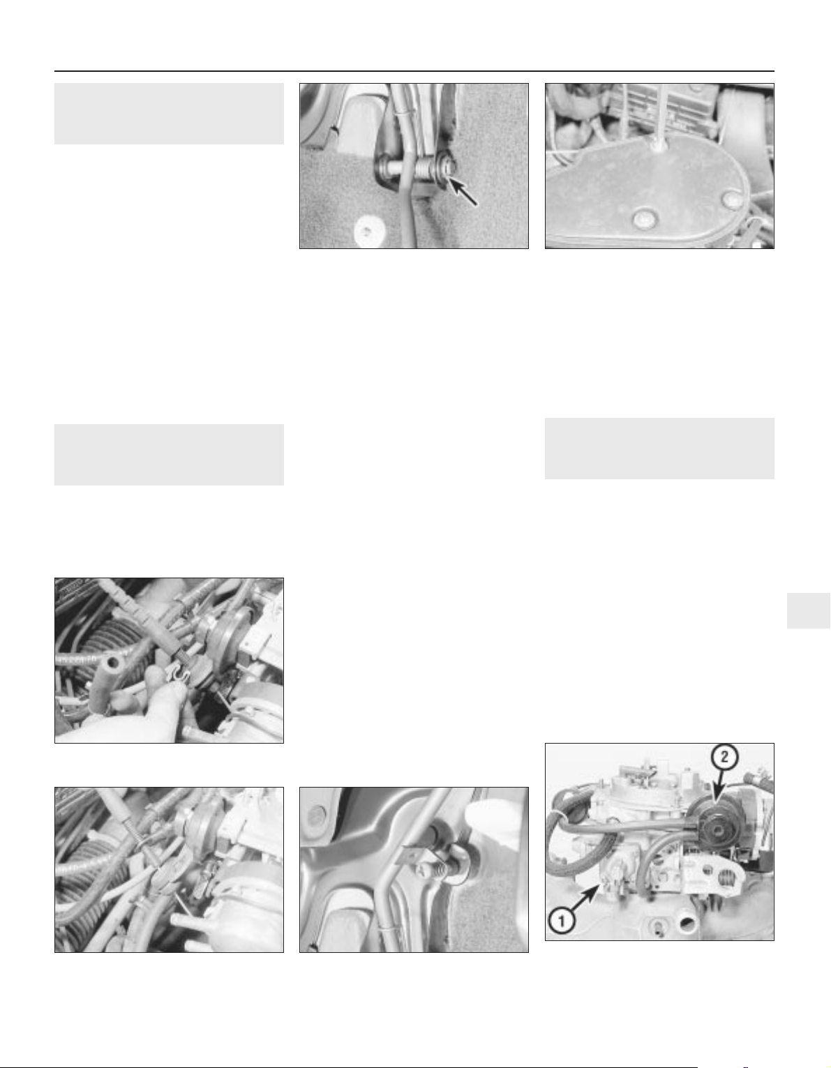
3 Extract the circlip from the right-hand end
of the pedal pivot shaft, then slide out the
pivot shaft from the left-hand side of the pivot
bracket (see illustration). Recover the pivot
bushes and the pedal return spring.
4 Examine the pivot bushes for wear, and
renew if necessary.
Refitting
5 Refitting is a reversal of removal, but on
completion check the throttle mechanism for
satisfactory operation, and check the throttle
cable adjustment, as described in Section 11.
11 Throttle cable — removal,
refitting and adjustment
3
Removal
1 Remove the air cleaner, on early models.
On later models, disconnect the air trunking
from the air cleaner, then disconnect the
vacuum pipe and breather hose from the air
box. Extract the three securing screws and lift
off the air box, complete with air trunking (see
illustration).
2 Extract the clip from the cable end fitting at
the bracket on the carburettor, then slide the
cable end grommet from the bracket (see
illustrations).
3 Slide the cable end from the throttle valve
lever on the carburettor.
4 Working inside the vehicle, remove the
lower trim panel from the driver’s footwell.
5 Slide the cable retainer from the bracket on
the top of the pedal, and disconnect the cable
end from the pedal.
6 Make a careful note of the cable routing,
then withdraw the cable through the bulkhead
into the engine compartment.
Refitting
7 Refitting is a reversal of removal,
remembering the following points.
8 Ensure that the cable is correctly routed, as
noted before removal.
9 Ensure that the bulkhead grommet is
correctly seated in its hole.
Adjustment
10 On completion, check the throttle
mechanism for satisfactory operation, and if
necessary adjust the cable, as described in
the following paragraphs.
11 Two points of cable adjustment are
provided. A stop screw is located on the
pedal arm to control the fully released position
of the pedal stop (see illustration). A clip is
located on a threaded section of the cable
sheath at the bracket on the carburettor, to
adjust the cable free play.
12 The cable should be adjusted so that
when the throttle pedal is released, there is
very slight free play in the cable at the
carburettor end.
13 Check that when the throttle pedal is fully
depressed, the throttle valve is fully open.
Adjust the position of the clip on the cable
sheath, and the pedal stop screw, to achieve
the desired results.
12 Carburettor — general
1 The Pierburg 2E3 carburettor is of twin-
venturi, fixed-jet sequential throttle type. The
primary throttle valve operates alone except
at high engine speeds and loads, when the
secondary throttle valve is operated, until at
full-throttle, both are fully open. This
arrangement allows good fuel economy
during light acceleration and cruising, but also
gives maximum power at full-throttle. The
secondary throttle valve is vacuum-operated,
according to the vacuum produced in the
primary venturi. The primary throttle barrel
and venturi diameters are smaller than their
secondary counterparts. The carburettor is a
complicated instrument, with various
refinements and sub-systems added to
achieve improved driveability, economy and
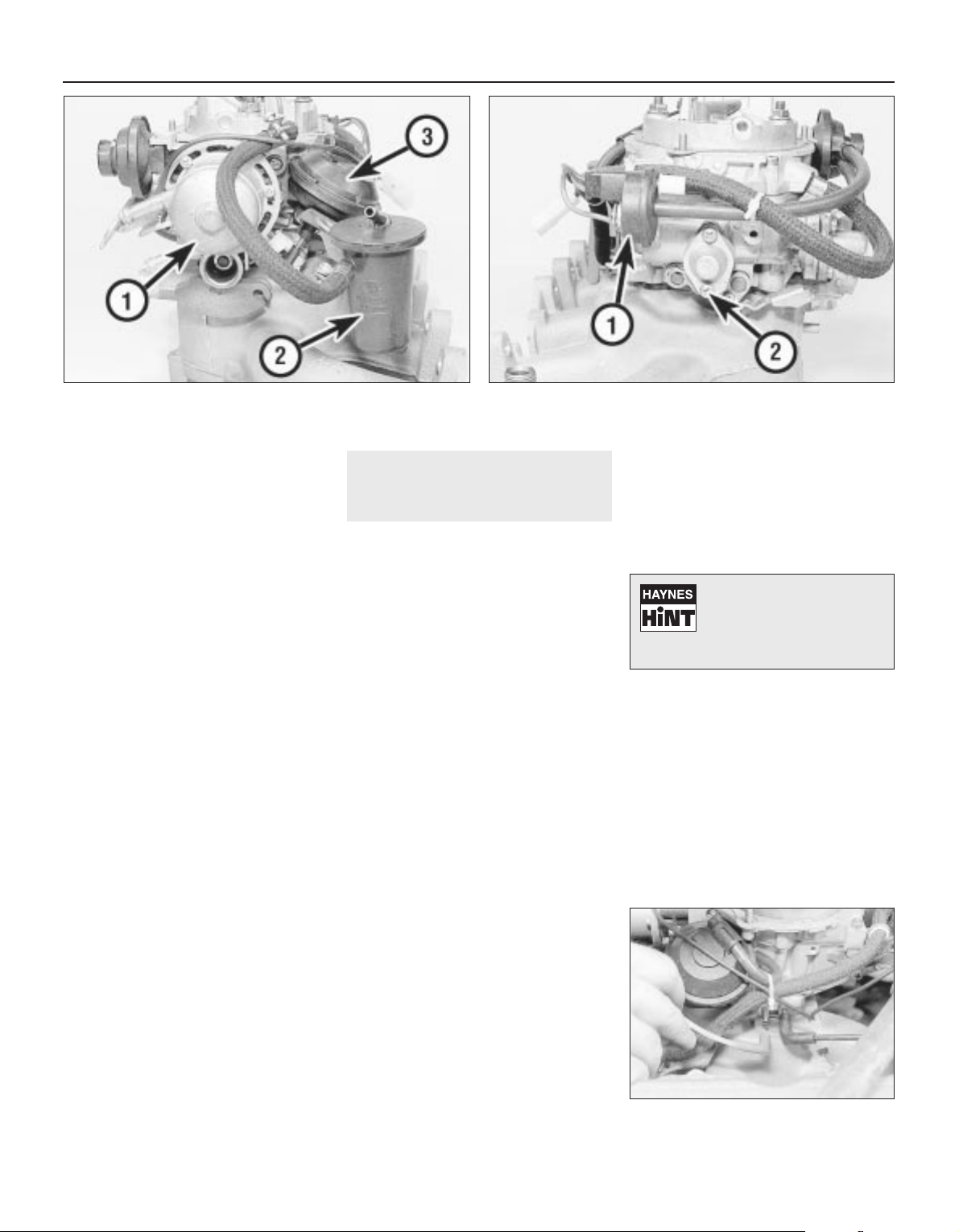
exhaust emission levels (see illustrations).
Fuel and exhaust systems — carburettor models 4A•5
11.2A Extract the throttle cable end
clip . . .
12.1A Side view of carburettor, showing
accelerator pump (1) and main choke pull-
down diaphragm unit (2)
11.11 Throttle pedal stop screw11.2B . . .and slide the grommet from the
bracket
11.1 Removing an air box securing screw10.3 Throttle pedal pivot assembly. Circlip
arrowed
4A
2 A separate idle system operates
independently from the main jet system,
supplying fuel by way of the mixture control
screw.
3 The main jets are calibrated to suit engine
requirements at mid-range throttle openings.
To provide the necessary fuel enrichment at
full throttle, a vacuum-operated power valve is
used. The valve provides extra fuel under the
low vacuum conditions associated with wide
throttle openings.
4 To provide an enriched mixture during
acceleration, an accelerator pump delivers
extra fuel to the primary main venturi. The
accelerator pump is operated mechanically by
a cam on the throttle linkage.
5 A fully automatic choke is fitted, operated
by a coolant and electrically heated bi-metal
coil. When the engine is cold, the bi-metal coil
is fully wound up, holding the choke plate
(fitted to the primary barrel) closed. As the
engine warms up, the bi-metal coil is heated
and therefore unwinds, progressively opening
the choke plate. A vacuum operated pull-
down system is employed, whereby, if the
engine is under choke but is only cruising (i.e.
not under heavy load) the choke plate is
opened against the action of the bi-metal coil.
The pull-down system prevents an over-rich
mixture, which reduces fuel economy and
may cause unnecessary engine wear when
the engine is cold. A secondary pull-down
solenoid is fitted, which operates in
conjunction with the main diaphragm unit to
modify the pull-down characteristics,
improving fuel economy.
6 1.8 litre models are fitted with an idle cut-off
solenoid. This is an electrically operated valve,
which interrupts the idle mixture circuit when
the ignition is switched off, this preventing
engine “run-on”.
13 Carburettor — removal,
overhaul and refitting
3
Note: Refer to Section 2 before proceeding.
New gasket(s) must be used when refitting the
carburettor. A tachometer and an exhaust gas
analyser will be required to check the idle
speed and mixture on completion
Removal
1 Disconnect the battery negative lead.
2 Remove the air cleaner, on early models.
On later models, disconnect the air trunking
from the air cleaner, then disconnect the
vacuum pipe and breather hose from the air
box. Extract the three securing screws and lift
off the air box, complete with air trunking.
3 On 1.4 litre models, disconnect the fuel
supply hose from the carburettor, and on 1.6
and 1.8 litre models, disconnect the fuel
supply and return hoses from the vapour
separator. Be prepared for fuel spillage, and
take adequate fire precautions. Plug the ends
of the hoses, to prevent dirt ingress and
further fuel spillage.
4 Extract the clip from the throttle cable end
fitting at the bracket on the carburettor, then
slide the cable end grommet from the bracket,
and slide the cable end from the throttle valve
lever.
5 Disconnect the coolant hoses from the
automatic choke housing noting their
locations, as an aid to refitting. Be prepared
for coolant spillage, and plug the hoses, or
secure them with their ends facing upwards,
to prevent further coolant loss.
6 Disconnect the vacuum pipes from the front
of the carburettor, noting their locations and
routing for use when refitting (see
illustration).
7 Disconnect the choke heater wire and any
additional wiring.
8 Unscrew the three securing nuts, and
withdraw the carburettor from the inlet
manifold studs.
9 Recover the gasket(s) and insulator block
that fit between the carburettor and the inlet
manifold.
Overhaul
10 With the carburettor removed from the
vehicle, drain the fuel from the float chamber
and vapour separator (where applicable).
Clean the outside of the carburettor, then
remove the top cover (Section 15).
11 Blow through the jets and drillings with
compressed air, or air from a foot pump — do
not probe them with wire. If it is wished to
remove the jets, unscrew them carefully with
well-fitting tools.
12 Remove the fuel filter gauze from the inlet
union, refer to Section 21, for details. Vauxhall
recommend that it is renewed whenever the
carburettor is cleaned.
4A•6 Fuel and exhaust systems — carburettor models
12.1B Side view of carburettor, showing automatic choke
housing (1), vapour separator (2) and secondary throttle valve
vacuum diaphragm (3)
12.1C Side view of carburettor, showing secondary choke pull-
down solenoid (1) and power valve (2)
13.6 Disconnecting the air box vacuum
pipe from the carburettor — 1.6 litre model
Aerosol cans of carburettor
cleaner are widely available
and can prove useful in
helping to clean internal
passages of stubborn obstructions.
13 Clean any foreign matter from the float
chamber. Renew the float, the float needle
valve and seat if wear is evident, or if the float
is punctured or otherwise damaged. Check
that the needle valve closes completely before
the float reaches the top of its movement. See
Section 15, for details of float level checking.
14 Renew the diaphragms in the part-load
enrichment valve and in the accelerator pump.
If additional pump or valve parts are supplied
in the overhaul kit, renew these parts also.
15 Further dismantling is not recommended.
Pay particular attention to the throttle opening
mechanism arrangement if it is decided to
dismantle it; the interlocking arrangement is
important.
16 Reassemble in the reverse order to
dismantling. Use new gaskets and seals
throughout; lubricate linkages with a smear of
molybdenum based grease.
Refitting
17 Carry out the following procedure before
refitting.
a) Position the fast idle adjustment screw on
the highest step of the fast idle cam.
b) Use a gauge rod or twist drill of the
specified diameter to measure the
opening of the primary throttle valve.
c) Adjust if necessary at the fast idle
adjustment screw.
d) Note that this is a preliminary adjustment;
final adjustment of the fast idle speed
should take place with the engine running.
18 Refitting is a reversal of removal, but
renew the gasket(s).
19 After refitting, carry out the following
checks and adjustments.
20 Check the throttle cable free play and
adjust if necessary, as described in Section 11.
21 Check and if necessary top-up the
coolant level, as described in Chapter 3.
22 Check and if necessary adjust the idle
speed and mixture, as described in Section 14.
14 Idle speed and mixture —
adjustment
3
Note: Refer to Section 2 before proceeding.
To carry out the adjustments, an accurate
tachometer and an exhaust gas analyser (CO
meter) will be required
1 To check the idle speed and mixture
adjustment, the following conditions must be
met:
a) The engine must be at normal operating
temperature
b) All electrical consumers (cooling fan,
heater blower, headlamps, etc.) must be
switched off
c) The ignition timing and spark plug gaps
must be correctly adjusted — see Chapters
1 and 5
d) The throttle cable free play must be
correctly adjusted — see Section 11
e) The air inlet trunking must be free from
leaks, and the air filter must be clean
f) On automatic models, always select
position, “P”.
2 Connect a tachometer and an exhaust gas
analyser to the vehicle, according to the
equipment manufacturer’s instructions.
3 Start the engine, and run it at 2000 rpm for
approximately 30 seconds, then allow it to
idle. If the idle speed is outside the specified
limits, adjust by means of the throttle stop
screw (see illustration).
4 When the idle speed is correct, check the
CO level in the exhaust gas. If it is outside the
specified limits, adjust by means of the idle
mixture adjustment screw. In production, the
screw is covered by a tamperproof plug;
ensure that no local or national laws are being
broken before removing the plug (see
illustration).
5 On automatic models, when position “D” is
selected (all electrical systems switched off),
the idle speed should not drop perceptibly. If
it does, the vehicle should be taken to a
Vauxhall dealer for the idle-up system to be
checked using special Vauxhall test
equipment.
6 With the idle mixture correct, readjust the
idle speed if necessary.
7 If the cooling fan cuts in during the
adjustment procedure, stop the adjustments,
and continue when the cooling fan stops.
8 When both idle speed and mixture are
correctly set, stop the engine and disconnect
the test equipment.
9 Fit a new tamperproof plug to the idle
mixture adjustment screw, where this is
required by law.
15 Needle valve and float —
removal, inspection and
refitting
4
Note: Refer to Section 2 before proceeding. A
new carburettor top cover gasket must be
used on reassembly. A tachometer and an
exhaust gas analyser will be required to check
the idle speed and mixture on completion
Removal
1 Disconnect the battery negative lead.
2 Remove the round air cleaner, on
applicable models. On other models,
disconnect the air trunking from the air
cleaner, then disconnect the vacuum pipe and
breather hose from the air box. Extract the
three securing screws and lift off the air box,
complete with air trunking.
3 Thoroughly clean all external dirt from the
carburettor.
4 Disconnect the fuel supply hose at the
carburettor. Be prepared for fuel spillage, and
take adequate fire precautions. Plug the end
of the hose, to prevent dirt ingress and further
fuel spillage.
5 Identify the automatic choke coolant hose
locations as an aid to refitting, then
disconnect the hoses. Be prepared for
coolant spillage, and either plug the hoses, or
secure them with their ends facing upwards,
to prevent further coolant loss.
6 Disconnect the choke heater wiring plug.
7 Disconnect the lower vacuum hoses from
the choke pull-down unit.
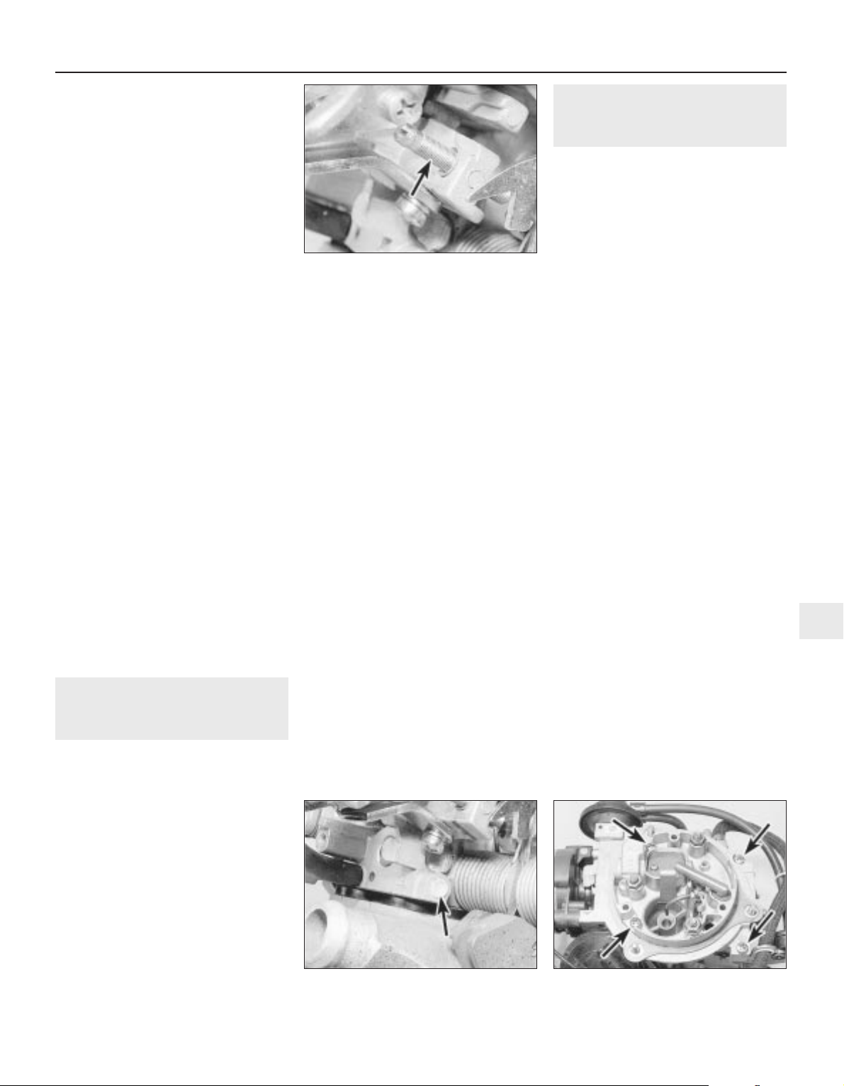
8 Remove the four carburettor top cover
securing screws, noting their locations, as two
lengths of screw are used (see illustration).
9 Lift off the top cover and recover the
gasket.
Inspection
10 Hold the cover vertically, so that the float
is hanging from its pivot. Then tilt the cover
until the float needle valve is just closed — the
needle spring must not be compressed by the
weight of the float.
11 Measure the distance, dimension x (see
illustration), from the bottom of the float to
the gasket surface on the top cover’s
Fuel and exhaust systems — carburettor models 4A•7
15.8 Carburettor top cover securing
screws (arrowed)
14.4 Tamperproof plug (arrowed) covering
idle mixture adjustment screw
14.3 Carburettor idle speed adjustment
(throttle stop) screw (arrowed)
4A
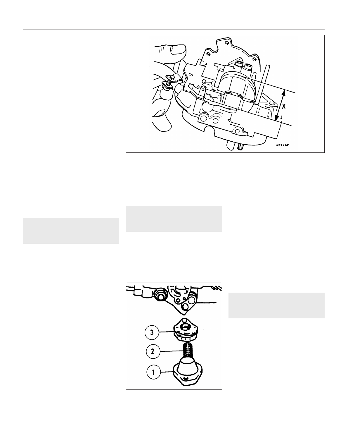
underside. If the distance measured exceeds,
or is less than, that specified, the float weight
is incorrect and the float must be renewed.
12 When the float level is known to be
correct, reassemble the carburettor, using a
new top cover gasket. Check the idle speed
and mixture settings as described in Section
14.
13 Using a pin punch, tap the float retaining
pin from the base of the top cover, and lift out
the float and needle valve.
14 Inspect the components for damage, and
renew as necessary. Check the needle valve
for wear, and check the float for leaks by
shaking it to see if it contains petrol.
15 Clean the mating faces of the carburettor
body and top cover.
Refitting
16 Refitting is a reversal of removal,
remembering the following points.
17 After refitting, check the float and needle
valve for full and free movement.
18 Use a new gasket between the top cover
and the carburettor body.
19 Ensure that all hoses, pipes and wires are
correctly reconnected.
20 On completion, check and if necessary
top-up the coolant level, as described in
Chapter 3, and check and if necessary adjust
the idle speed and mixture, as described in
Section 14.
16 Secondary throttle valve
vacuum diaphragm — testing,
removal and refitting
3
Note: The diaphragm unit must be renewed in
its entirety, as no spares are available
Testing
1 If a vacuum source incorporating a gauge is
available, apply approximately 300 mbars (9 in
Hg) to the diaphragm unit, at the hose nearest
the carburettor body. Close off the vacuum
source, and check that the vacuum is held. If
there is a leak, rectify or renew the leaking
component. Alternately, testing of a suspect
vacuum unit must be by the substitution of a
known good item.
Removal
2 Remove the air cleaner, on early models.
On later models, disconnect the air trunking
from the air cleaner, then disconnect the
vacuum pipe air breather hose from the air
box. Extract the three securing screws and lift
off the air box, complete with air trunking.
3 Disconnect the vacuum pipe from the
diaphragm unit.
4 Prise the diaphragm operating rod balljoint
from the secondary throttle valve linkage.
5 On 1.6 and 1.8 litre models, remove the two
securing screws and lift the vapour separator
from the bracket. Move the vapour separator
to one side, taking care not to strain the fuel
hoses.
6 Remove the three securing screws, and
withdraw the diaphragm unit complete with its
bracket from the carburettor body.
Refitting
7 Refitting is a reversal of removal.
17 Power valve diaphragm —
removal and refitting
3
Note: Refer to Section 2 before proceeding
Removal
1 Disconnect the battery negative lead.
2 Remove the air cleaner, on early models.
On later models, disconnect the air trunking
from the air cleaner, then disconnect the
vacuum pipe and breather hose from the air
box. Extract the three securing screws and lift
off the air box, complete with air trunking.
3 Thoroughly clean all external dirt from the
area around the power valve housing.
4 Remove the two securing screws, and lift
off the power valve cover, spring, and
diaphragm assembly.
Refitting
5 Clean the mating faces of the cover and
housing.
6 Locate the spring on the cover and
diaphragm assembly, ensuring that it is
correctly seated, then press the diaphragm
assembly and cover together. Note that the
vacuum hole in the diaphragm must align with
the corresponding holes in the housing flange
and cover.
7 Further refitting is a reversal of removal, but
ensure that the diaphragm is correctly seated
(see illustration).
18 Accelerator pump — testing,
removal and refitting
3
Note: Refer to Section 2 before proceeding
Testing
1 It will be necessary to feed the float
chamber with fuel from a small reservoir
during this test.
2 Position the primary barrel over an accurate
measuring glass. Fully open and close the
throttle ten times, taking approximately one
second for each opening, and pausing for
three seconds after each return stroke. Make
sure that the fast idle cam is not restricting
throttle travel at either end.
3 Measure the quantity of fuel delivered, and
compare this with the specified value.
4A•8 Fuel and exhaust systems — carburettor models
15.11 Measuring the float level “X”
17.7 Carburettor power valve components
1 Cover
2 Spring
3 Diaphragm
assembly
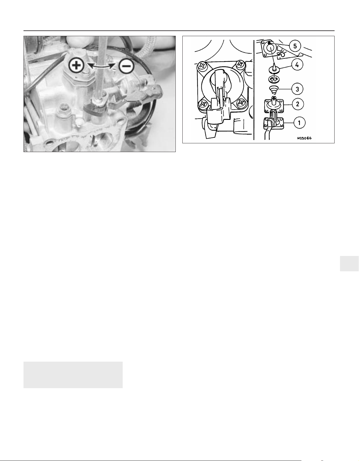
4 If adjustment is necessary, release the
clamp screw and turn the cam plate in the
desired direction. Tighten the clamp screw,
and recheck the pump delivery (see
illustration).
Removal
5 Proceed as described in Section 17,
paragraphs 1 and 2.
6 Thoroughly clean all external dirt from the
area around the accelerator pump housing.
7 Remove the four securing screws and lift off
the accelerator pump cover. Recover the
diaphragm, spring, valve retainer and valve.
Note the orientation of the valve retainer.
Refitting
8 Clean the mating faces of the cover and
housing.
9 Check the condition of the valve, and renew
if necessary.
10 Begin refitting by locating the valve, valve
retainer and spring in the housing. Note that
the valve retainer can only be fitted in one
position. The larger diameter of the spring
should rest against the valve retainer.
11 Locate the diaphragm on the housing,
ensuring that the spring is correctly seated,
and refit the cover. Tighten the cover securing
screws progressively to avoid distorting the
diaphragm (see illustration).
12 Further refitting is a reversal of removal.
19 Automatic choke unit —
removal, refitting and
adjustment
3
Note: Refer to Section 2 before proceeding. A
tachometer and an exhaust gas analyser will
be required to check the idle speed and
mixture on completion. If the coolant housing
is removed, new O-rings will be required for
refitting
Removal
1 Proceed as described in Section 17,
paragraphs 1 and 2.
2 Note the position of the bi-metal housing
alignment marks as an aid to refitting, if
necessary making additional marks for clarity,
then remove the three securing screws and lift
off the bi-metal housing. Place the housing to
one side, taking care not to strain the coolant
hoses or electric choke heater wiring.
3 Remove the three screws securing the
choke housing to the carburettor body, and
withdraw the choke assembly, taking care not
to bend the choke operating rod.
4 If it is necessary to remove the bi-metal
housing for renewal, continue as follows;
otherwise go on to paragraph 8.
5 Identify the automatic choke coolant hose
locations as an aid to refitting, then
disconnect the hoses. Be prepared for
coolant spillage, and either plug the hoses, or
secure them with their ends facing upwards,
to prevent further loss of coolant.
6 Disconnect the wiring from the electric
choke heater, and withdraw the bi-metal
housing.
7 The coolant housing can be separated from
the bi-metal housing by unscrewing the
central securing bolt. Recover the O-rings
from under the bolt head, and from the rim of
the coolant housing.
Refitting
8 Begin refitting by locating the choke
assembly on the carburettor body, ensuring
that the lever on the choke assembly engages
with the choke operating rod. Tighten the
three securing screws.
9 Check and if necessary adjust the choke
valve gap and the fast idle cam position, as
described in paragraphs 15 to 19, of this
Section.
10 Connect the bi-metal spring to the choke
lever, position the bi-metal housing on the
choke housing, and loosely fit the securing
screws. Align the marks on the bi-metal
housing and the choke housing as noted
during removal, then tighten the securing
screws.
11 Where applicable, refit the coolant
housing to the bi-metal housing, using new O-
rings if necessary, and reconnect the coolant
hoses and electric choke heater wiring.
12 Further refitting is a reversal of removal,
remembering the following points.
13 If the coolant hoses have been
disconnected, check the coolant level, as
described in Chapter 3.
14 Check and if necessary adjust the fast idle
speed, as described in paragraphs 25 to 34,
of this Section.
Adjustment
Choke valve gap
15 With the bi-metal housing removed as
described in paragraphs 2 to 4, of this
Section, continue as follows.
16 Press the choke operating lever fully
clockwise, and retain it in position with a
rubber band.
17 Move the throttle lever to the fully open
position, and measure the choke valve gap
between the lower side of the choke plate and
the wall of the primary barrel. Check that the
gap is as given in the Specifications.
18 If necessary, adjust the choke valve gap
by bending the “adjuster segment (2)” If the
gap is too small, enlarge gap “B”, by levering
with a screwdriver. If the gap is too large,
decrease gap “B” using a pair of pliers (see
illustration).
19 If no further adjustments are to be carried
out, refit the bi-metal housing, as described in
paragraphs 10 to 14, of this Section.
Fuel and exhaust systems — carburettor models 4A•9
18.11 Carburettor accelerator pump components
1 Cover with operating lever
2 Diaphragm
3 Spring
4 Valve
5 Air passage
18.4 Accelerator pump delivery adjustment: “+” to
increase, “-” to reduce
4A
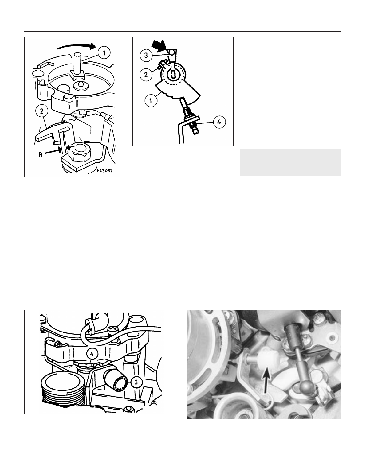
Fast idle cam position
20 With the bi-metal housing removed, and
the choke valve gap “B”, correctly set,
continue as follows.
21 Open the throttle valve, then close the
choke valve using light finger pressure on the
choke drive lever (see illustration). Close the
throttle valve.
22 Check that the fast idle speed adjustment
screw is resting against the stop on the
second highest step of the fast idle cam.
23 If adjustment is required, first check that
the choke return spring is correctly
positioned, then adjust by bending the
adjustment lever.
24 Refit the bi-metal housing, as described in
paragraphs 10 to 14 of this Section.
Fast idle speed
Note: To carry out the adjustment, an
accurate tachometer and an exhaust gas
analyser (CO meter) will be required
25 Check the idle speed and mixture, as
described in Section 14. The idle speed must
be correct before attempting to check or
adjust the fast idle speed.
26 With the engine at normal operating
temperature, and a tachometer connected
according to the equipment manufacturer’s
instructions, continue as follows.
27 Position the fast idle speed adjustment
screw on the second highest step of the fast
idle cam (see illustration).
28 Start the engine without touching the
throttle pedal, and check that the fast idle
speed is as specified. If adjustment is
required, stop the engine and continue as
follows.
29 Remove the tamperproof cap from the
fast idle speed adjustment screw, ensure that
no local or national laws are being broken by
doing so (see illustration).
30 Ensure that the adjustment screw is still
resting on the second highest step of the fast
idle cam, then start the engine, again without
touching the throttle pedal.
31 Turn the adjustment screw using a
screwdriver, until the specified fast idle speed
is obtained.
32 If the cooling fan cuts in during the
adjustment procedure, stop the adjustments,
and continue when the cooling fan stops.
33 On completion of adjustment, stop the
engine and disconnect the tachometer.
34 Fit a new tamperproof cap to the fast idle
speed adjustment screw, where this is
required by law.
20 Automatic choke vacuum
pull-down units — removal,
refitting and adjustment
3
Main diaphragm unit
Note: Refer to Section 2 before proceeding. A
new star clip must be used when refitting the
diaphragm unit. Test vacuum units as
described in Section 16, paragraph 1.
Removal
1 Proceed as described in Section 17,
paragraphs 1 and 2.
2 Disconnect the diaphragm unit vacuum
pipes.
3 Using a pin punch, tap out the roll pin
securing the diaphragm unit to the carburettor
top cover.
4 Note the position of the bi-metal housing
alignment marks as an aid to refitting, if
necessary making additional marks for clarity,
then remove the three securing screws, and
lift off the bi-metal housing. Place the housing
to one side, taking care not to strain the
coolant hoses or electric choke heater wiring.
4A•10 Fuel and exhaust systems — carburettor models
19.18 Choke valve gap adjustment
1 Choke operating lever
2 Adjuster segment
B Choke valve gap
19.21 Fast idle cam adjustment
1 Fast idle cam
2 Adjustment lever
3 Choke drive lever
4 Fast idle speed adjustment screw
19.29 Tamperproof cap (arrowed) fast idle speed adjustment
screw
19.27 Fast idle speed adjustment
3 Fast idle speed adjustment screw
4 Screw positioned on second highest step of cam
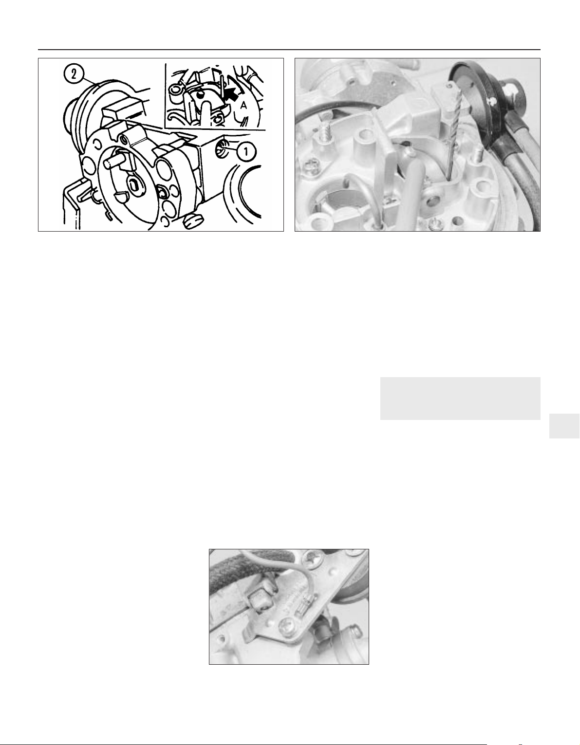
5 Remove the three screws securing the
choke assembly to the carburettor body.
Allow the choke assembly to drop down, but
do not disconnect the choke linkage.
6 Remove the star clip that secures the
diaphragm unit to the carburettor top cover,
and withdraw the diaphragm unit.
Refitting
7 Refitting is a reversal of removal, but use a
new star clip to secure the diaphragm unit to
the carburettor top cover. Before refitting the
air box to the top of the carburettor, check
and if necessary adjust the choke pull-down,
as follows.
Vacuum pull-down
Adjustment
8 With the air cleaner or air box removed from
the top of the carburettor, as described in
Section 17, paragraph 2, continue as follows.
9 Note the position of the bi-metal housing
alignment marks as an aid to refitting, if
necessary making additional marks for clarity,
then remove the three securing screws, and
lift off the bi-metal housing. Place the housing
to one side, taking care not to strain the
coolant hoses or electric choke heater wiring.
10 Position the fast idle speed adjustment
screw on the highest step of the fast idle cam,
and check that the choke valve is closed.
11 Move the pull-down arm towards the
diaphragm unit by pushing on the adjustment
screw until resistance is felt. Hold the arm in
this position.
12 Using a drill shank of appropriate
diameter, or a similar item, measure the
clearance between the lower side of the
choke plate and the wall of the primary barrel
(see illustrations). Check that the clearance
is as given for the “small” choke pull-down
gap in the Specifications.
13 If adjustment is necessary, turn the
adjustment screw in the appropriate direction,
using an Allen key, until the clearance is
correct.
14 Now push the pull-down arm towards the
diaphragm unit as far as its stop, and hold the
arm in this position.
15 As before measure the clearance between
the lower side of the choke plate and the wall
of the primary barrel. Check that the
clearance is as given for the “large” choke
pull-down gap in the Specifications.
16 If adjustment is necessary, turn the
adjustment screw in the appropriate direction
until the clearance is correct.
17 Connect the bi-metal spring to the choke
lever, position the bi-metal housing on the
choke housing and loosely fit the securing
screws. Align the marks on the bi-metal
housing and the choke housing as noted
during removal, then tighten the securing
screws.
18 Refit the air box to the top of the
carburettor on completion.
Secondary pull-down solenoid
Removal
19 This unit operates in conjunction with the
main diaphragm unit.
20 To remove the solenoid unit, first continue
as described in Section 17, paragraphs 1 and
2.
21 Disconnect the diaphragm unit vacuum
pipe.
22 Disconnect the wiring plug, then unscrew
the securing screw, and withdraw the
solenoid unit and its mounting bracket from
the carburettor. Note that the securing screw
also secures the wiring plug earth lead (see
illustration).
Refitting
23 Refitting is a reversal of removal, but
ensure that the wiring plug earth lead is in
place under the solenoid bracket securing
screw.
21 Carburettor filter — removal
and refitting
3
Removal
1 A small tubular filter gauze is fitted into the
carburettor top cover’s fuel inlet union to
remove any particles of dirt from the fuel.
2 To ensure a clean fuel supply and to
prevent the risk of misfiring, poor starting or
other problems due to a restricted fuel supply,
this filter must be cleaned and/or renewed at
the interval specified in Chapter 1.
3 To reach the filter, remove the air cleaner or
air box, as applicable, then disconnect and
plug the hose from the fuel pump or vapour
separator to the top cover union.
4 Remove the filter by hooking it out with a
small screwdriver, or by snaring it with a long
thin screw (3 mm thread size, screwed
approximately 5 mm into the filter).
5 If the filter is blocked or heavily fouled, or if
it is torn, distorted or damaged in any way, it
must be renewed. If it is fit for further use,
clean it using a jet of compressed air or by
brushing away particles of dirt with an old soft
toothbrush. Then flushing it in clean solvent,
taking care not to allow any overspray to get
into your eyes; if petrol is used, take care to
prevent the risk of fire.
Fuel and exhaust systems — carburettor models 4A•11
20.12B Checking the vacuum pull-down gap using a twist drill
20.22 Secondary choke pull-down
solenoid securing screw and earth lead
20.12A Choke vacuum pull-down adjustment
1 Adjustment screw 2 Diaphragm unit A Twist drill
4A
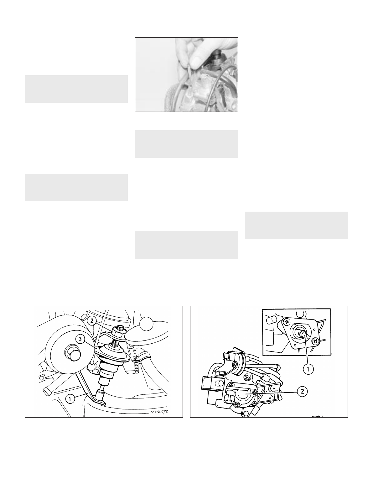
Refitting
6 On refitting the filter, press it into the union
until it catches (see illustration). The
remainder of the reassembly procedure is the
reverse of removal.
22 Throttle valve dashpot
(automatic models) —
adjustment
2
1 Remove the air cleaner or air box, refer to
Section 3.
2 Ensure that the lever (see illustration) is in
the idling position.
3 Slacken the locknut and unscrew the
dashpot until a gap of 0.05 mm (0.002 in)
exists between the lever and the dashpot tip.
Then screw the dashpot downwards 2.5 full
turns and tighten the locknut.
4 Refit all removed components.
23 Throttle position sensor
(automatic transmission
models) — removal and refitting
2
Removal
1 Disconnect the battery earth lead.
2 Disconnect the wiring plug from the sensor.
3 Either unscrew the two securing screws
and withdraw the sensor from its bracket, or
unbolt the bracket.
Refitting
4 Refitting is the reverse of the removal
procedure, noting the following points.
a) Install the sensor when the throttle valve
is fully closed and ensure that the
adapter, “1” (see illustration), seats
correctly on the throttle valve spindle.
b) Tighten the screws carefully.
24 Idle speed increase valve —
testing
2
1 Certain models are fitted with an idle speed
increase valve that is attached to the side of
the carburettor.
2 To test the operation of this valve first
remove the air filter and vacuum hose.
3 With the valve’s plug connected, have
someone turn the ignition on (but do not start
the engine). A mechanical shifting noise
should be heard. If not replace the unit.
4 After refitting replace the vacuum hose and
air filter.
25 Idle cut-off solenoid (1.8 litre
models) — description and
testing
2
Note: Refer to Section 2 before proceeding
Description
1 On 1.8 litre models, the carburettor is fitted
with an idle cut-off solenoid. This is an
electrically operated valve, which interrupts
the idle mixture circuit when the ignition is
switched off, thus preventing the engine from
running-on (see illustration).
2 The idle cut-off solenoid is energised all the
time that the ignition is switched on. A
defective solenoid, or a break in its power
supply, will cause the engine to stall or idle
roughly, although it will run normally at speed.
Testing
3 If the operation of the solenoid is suspect,
first check that battery voltage is present at
the solenoid terminal when the ignition is
switched on. Use a 12 volt test lamp or similar
test device.
4 If no voltage is present, then the fault lies in
the wiring to the solenoid. If voltage is
present, the solenoid can be tested as
follows.
5 With the solenoid unscrewed from the
carburettor, connect the body of the solenoid
to the negative terminal of a 12 volt battery.
When the battery positive terminal is
connected to the solenoid centre terminal,
there should be an audible click, and the
needle at the tip of the solenoid should
retract.
6 A defective idle cut-off solenoid must be
renewed.
26 Inlet manifold — removal and
refitting
3
Note: Refer to Section 2 before proceeding. A
new manifold gasket must be used on refitting
Removal
1 Disconnect the battery negative lead.
2 Drain the cooling system, as described in
Chapter 3.
3 Proceed as described in Section 13,
paragraphs 2 to 7 inclusive, ignoring the
reference to coolant spillage in paragraph 5.
4A•12 Fuel and exhaust systems — carburettor models
21.6 Refitting the carburettor fuel filter
23.4 Throttle position sensor — models with automatic
transmission
1 Adapter 2 Sensor
22.2 Adjusting the throttle valve dashpot — models with
automatic transmission
1 Lever 2 Locknut 3 Dashpot
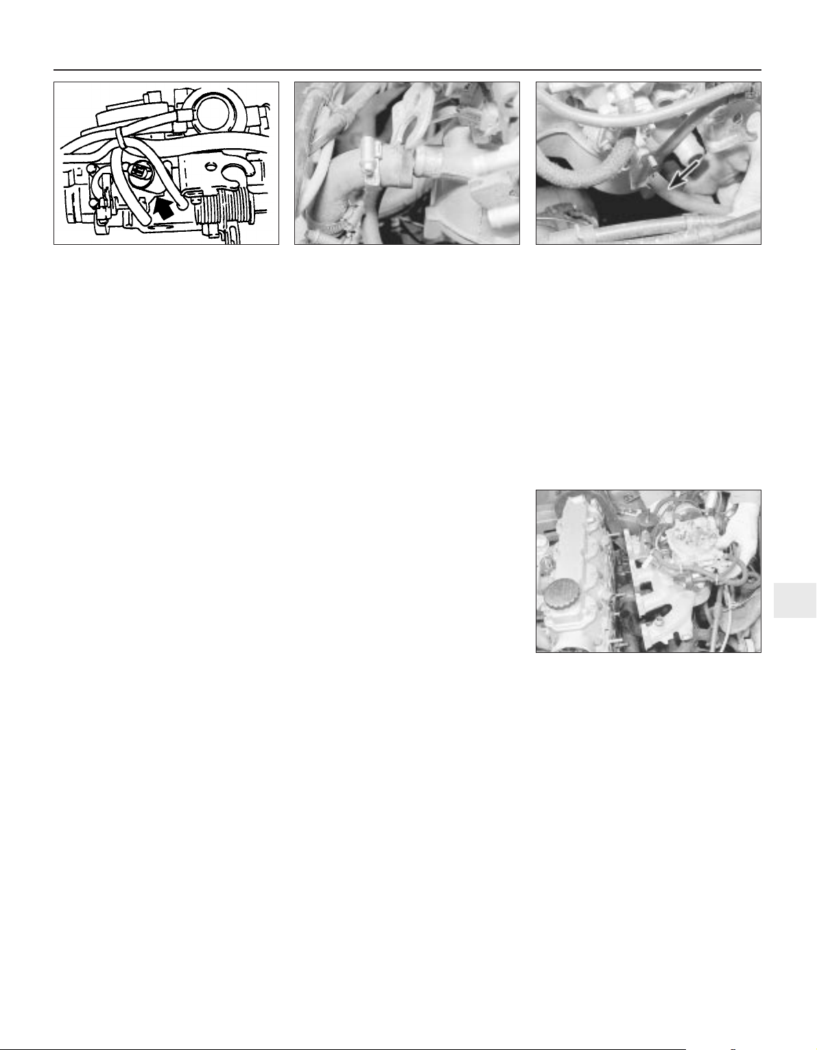
4 Disconnect the coolant hose from the rear
of the manifold (see illustration).
5 Where applicable, disconnect the camshaft
cover breather hose from the rear of the
manifold (see illustration).
6 Unscrew the union and disconnect the
brake servo vacuum hose from the manifold.
7 On 1.4 and 1.6 litre models, disconnect the
wiring from the temperature gauge sender.
8 Unscrew and remove the top alternator
mounting nut and bolt.
9 On 1.4 and 1.6 litre models, disconnect and
remove the stub hose that connects the
crankcase breather tube to the rear of the
camshaft housing.
10 Make a final check to ensure that all
relevant hoses, pipes and wires have been
disconnected.
11 Unscrew the securing nuts, and withdraw
the manifold from the cylinder head (see
illustration). Note the position of the rear
engine lifting bracket, which is secured by one
of the manifold nuts, and recover the manifold
gasket.
12 It is possible that some of the manifold
studs may be unscrewed from the cylinder
head when the manifold securing nuts are
unscrewed. In this event, the studs should be
screwed back into the cylinder head once the
manifold has been removed, using two
manifold nuts locked together.
13 If desired, the carburettor can be removed
from the manifold, referring to Section 13, if
necessary.
Refitting
14 Refitting is a reversal of removal,
remembering the following points.
15 If the carburettor has been removed from
the manifold, refit it, using a new gasket.
16 If the alternator mounting bracket has
been unbolted from the manifold, refit it
before refitting the manifold, as access to the
securing bolt is extremely limited once the
manifold is in place.
17 Refit the manifold using a new gasket,
and ensure that the engine lifting bracket is in
place under the relevant manifold nut. Tighten
the nuts to the specified torque.
18 Ensure that all relevant hoses, pipes and
wires are correctly reconnected.
19 Refill the cooling system, as described in
Chapter 3.
20 Check the throttle cable free play and
adjust if necessary, as described in Section
11.
21 If the carburettor has been disturbed,
check and if necessary adjust the idle speed
and mixture, as described in Section 14.
Fuel and exhaust systems — carburettor models 4A•13
26.5 . . .and the camshaft cover breather
hose (arrowed) from the inlet manifold —
1.6 litre model
26.11 Withdrawing the inlet manifold —
1.6 litre model
26.4 Disconnecting the coolant hose . . .
4A
25.1 Carburettor idle cut-off solenoid
(arrowed) — 1.8 litre models


12
Wiper blades
Type . . . . . . . . . . . . . . . . . . . . . . . . . . . . . . . . . . . . . . . . . . . . . . . . . . . . 19 ins. Champion X-4803
Fuses
Rating:
Red . . . . . . . . . . . . . . . . . . . . . . . . . . . . . . . . . . . . . . . . . . . . . . . . . . . 10 A
Blue . . . . . . . . . . . . . . . . . . . . . . . . . . . . . . . . . . . . . . . . . . . . . . . . . . . 15 A
Yellow . . . . . . . . . . . . . . . . . . . . . . . . . . . . . . . . . . . . . . . . . . . . . . . . . 20 A
Green . . . . . . . . . . . . . . . . . . . . . . . . . . . . . . . . . . . . . . . . . . . . . . . . . 30 A
Torque wrench settings Nm lbf ft
Airbag unit to steering wheel . . . . . . . . . . . . . . . . . . . . . . . . . . . . . . . . . 10 7
Airbag control . . . . . . . . . . . . . . . . . . . . . . . . . . . . . . . . . . . . . . . . . . . . . 10 7
Brackets, passenger airbag . . . . . . . . . . . . . . . . . . . . . . . . . . . . . . . . . . 22 16
Passenger airbag to bracket . . . . . . . . . . . . . . . . . . . . . . . . . . . . . . . . . 8 6
Steering to column . . . . . . . . . . . . . . . . . . . . . . . . . . . . . . . . . . . . . . . . . 25 18
Chapter 12
Body electrical systems
Aerial — removal and refitting . . . . . . . . . . . . . . . . . . . . . . . . . . . . . . .47
Aerial mast, electric — removal and refitting . . . . . . . . . . . . . . . . . . . .48
Airbag — general . . . . . . . . . . . . . . . . . . . . . . . . . . . . . . . . . . . . . . . . .55
Airbag contact unit — removal and refitting . . . . . . . . . . . . . . . . . . . . .58
Airbag control unit — removal and refitting . . . . . . . . . . . . . . . . . . . . .61
Airbag unit, drivers side — removal and refitting . . . . . . . . . . . . . . . . .56
Airbag unit, passengers side — removal and refitting . . . . . . . . . . . . .59
Anti-theft alarm — general . . . . . . . . . . . . . . . . . . . . . . . . . . . . . . . . . .53
Anti-theft alarm system components — removal and refitting . . . . . . .54
Bracket, passenger airbag unit — removal and refitting . . . . . . . . . . .60
Brake lamp switch — removal and refitting . . . . . . . . . . . . . . . . . . . . .12
Central door locking components — removal and refitting . . . . . . . . .46
Check control system components — removal and refitting . . . . . . . .21
Cigarette lighter — removal and refitting . . . . . . . . . . . . . . . . . . . . . . .15
Clock — removal and refitting . . . . . . . . . . . . . . . . . . . . . . . . . . . . . . .16
Courtesy lamp switch — removal and refitting . . . . . . . . . . . . . . . . . . .10
Direction indicator/lighting switch — removal and refitting . . . . . . . . . .5
Electric door mirror switch — removal and refitting . . . . . . . . . . . . . . . .8
Electric window components — removal and refitting . . . . . . . . . . . . .44
Electric window controls — programming . . . . . . . . . . . . . . . . . . . . . .45
Electrical fault-finding — general information . . . . . . . . . . . . . . . . . . . . .2
Exterior lamp bulbs — renewal . . . . . . . . . . . . . . . . . . . . . . . . . . . . . . .34
Facia panel switches — removal and refitting . . . . . . . . . . . . . . . . . . . .7
Front indicator lamp unit — removal and refitting . . . . . . . . . . . . . . . .29
Front foglamp — removal, refitting and adjustment . . . . . . . . . . . . . . .31
Fuses and relays — general . . . . . . . . . . . . . . . . . . . . . . . . . . . . . . . . . .3
General information and precautions . . . . . . . . . . . . . . . . . . . . . . . . . .1
Handbrake “on” warning lamp switch — removal and refitting . . . . . .13
Headlamp aim adjustment motor — removal and refitting . . . . . . . . . .26
Headlamp dim-dip system — general, removal and refitting . . . . . . . .28
Headlamp unit — removal and refitting . . . . . . . . . . . . . . . . . . . . . . . .25
Headlamp washer fluid non-return valve — removal and refitting . . . .43
Headlamp wiper motor — removal and refitting . . . . . . . . . . . . . . . . . .40
Headlamps — alignment . . . . . . . . . . . . . . . . . . . . . . . . . . . . . . . . . . .27
Heated front seats — general . . . . . . . . . . . . . . . . . . . . . . . . . . . . . . . .17
Horn(s) — removal and refitting . . . . . . . . . . . . . . . . . . . . . . . . . . . . . .22
Ignition switch and lock cylinder — removal and refitting . . . . . . . . . . .4
Instrument panel — removal and refitting . . . . . . . . . . . . . . . . . . . . . .18
Instrument panel components — removal and refitting . . . . . . . . . . . .19
Interior lamp bulbs — renewal . . . . . . . . . . . . . . . . . . . . . . . . . . . . . . .24
Interior lamps — removal and refitting . . . . . . . . . . . . . . . . . . . . . . . . .23
Luggage compartment lamp switch — removal and refitting . . . . . . .11
Number plate lamp — removal and refitting . . . . . . . . . . . . . . . . . . . . .33
Oil pressure warning lamp switch — removal and refitting . . . . . . . . .14
Radio/cassette player — removal and refitting . . . . . . . . . . . . . . . . . . .50
Rear lamp unit — removal and refitting . . . . . . . . . . . . . . . . . . . . . . . .32
Reversing lamp switch . . . . . . . . . . . . . . . . . . . . . . . . .See Chapter 7A
Side repeater lamp — removal and refitting . . . . . . . . . . . . . . . . . . . . .30
Speakers — removal and refitting . . . . . . . . . . . . . . . . . . . . . . . . . . . .49
Speedometer cable — removal and refitting . . . . . . . . . . . . . . . . . . . .52
Steering wheel (with airbag) — removal and refitting . . . . . . . . . . . . . .57
Sunroof motor — removal and refitting . . . . . . . . . . . . . . . . . . . . . . . .51
Sunroof operating switch — removal and refitting . . . . . . . . . . . . . . . . .9
Tailgate wiper motor — removal and refitting . . . . . . . . . . . . . . . . . . . .39
Trip computer components — removal and refitting . . . . . . . . . . . . . .20
Wash/wipe switch — removal and refitting . . . . . . . . . . . . . . . . . . . . . .6
Washer fluid reservoir — removal and refitting . . . . . . . . . . . . . . . . . . .41
Washer nozzles — removal and refitting . . . . . . . . . . . . . . . . . . . . . . .37
Washer pump — removal and refitting . . . . . . . . . . . . . . . . . . . . . . . . .42
Windscreen wiper motor and linkage — removal and refitting . . . . . . .38
Wiper arms — removal and refitting . . . . . . . . . . . . . . . . . . . . . . . . . . .36
Wiper blades — renewal . . . . . . . . . . . . . . . . . . . . . . . . . . . . . . . . . . . .35
Wiring diagrams — general . . . . . . . . . . . . . . . . . . . . . . . . . . . . . . . . .62
12•1
Specifications
Contents
Easy, suitable for
novice with little
experience
Fairly easy, suitable
for beginner with
some experience
Fairly difficult,
suitable for competent
DIY mechanic
Difficult, suitable for
experienced DIY
mechanic
Very difficult,
suitable for expert DIY
or professional
Degrees of difficulty
5
4
3
2
1
1 General information and
precautions
The electrical system is of 12-volt negative
earth type. Power for the lights and all
electrical accessories is supplied by a
lead/acid type battery, which is charged by
the alternator.
This Chapter covers repair and service
procedures for the various electrical
components not associated with engine.
Information on the battery, alternator and
starter motor can be found in Chapter 5.
It should be noted that, before working on
any component in the electrical system, the
battery negative terminal should first be
disconnected, to prevent the possibility of
electrical short-circuits and/or fires.
Whenever the occasion arises, carefully
check the routing of the wiring harness,
ensuring that it is correctly secured by the
clips or ties provided so that it cannot chafe
against other components. Carefully check
points such as the clutch cable bracket,
clutch housing and harness support bracket,
the inlet manifold, the horn mounting bracket,
the starter motor terminals, and the rear
bumper and number plate lamp.
If evidence is found of the harness having
chafed against other components, repair the
damage and ensure that the harness is
secured or protected so that the problem
cannot occur again.
2 Electrical fault-finding —
general information
Note: Refer to the precautions given in “Safety
first!” (at the beginning of this manual) and to
Section 1 of this Chapter before starting work.
The following tests relate to testing of the main
electrical circuits, and should not be used to
test delicate electronic circuits (such as anti-
lock braking systems), particularly where an
electronic control module is used.
A typical electrical circuit consists of an
electrical component, any switches, relays,
motors, fuses, fusible links or circuit breakers
related to that component, and the wiring and
connectors that link the component to both
the battery and the chassis. To help to
pinpoint a problem in an electrical circuit,
wiring diagrams are included at the end of this
Chapter.
Before attempting to diagnose an electrical
fault, first study the appropriate wiring
diagram, to obtain a complete understanding
of the components included in the particular
circuit concerned. The possible sources of a
fault can be narrowed down by noting
whether other components related to the
circuit are operating properly. If several
components or circuits fail at one time, the
problem is likely to be related to a shared fuse
or earth connection.
Electrical problems usually stem from
simple causes, such as loose or corroded
connections, a faulty earth connection, a
blown fuse, a melted fusible link, or a faulty
relay (refer to Section 3 for details of testing
relays). Visually inspect the condition of all
fuses, wires and connections in a problem
circuit before testing the components. Use
the wiring diagrams to determine which
terminal connections will need to be checked,
to pinpoint the trouble-spot.
The basic tools required for electrical fault-
finding include the following:
a) a circuit tester or voltmeter (a 12-volt bulb
with a set of test leads can also be used
for certain tests).
b) a self-powered test light (sometimes
known as a continuity tester).
c) an ohmmeter (to measure resistance).
d) a battery.
e) a set of test leads.
f) a jumper wire, preferably with a circuit
breaker or fuse incorporated, which can
be used to bypass suspect wires or
electrical components.
Before attempting to locate a problem with
test instruments, use the wiring diagram to
determine where to make the connections.
To find the source of an intermittent wiring
fault (usually due to a poor or dirty
connection, or damaged wiring insulation), a
“wiggle” test can be performed on the wiring.
This involves wiggling the wiring by hand, to
see if the fault occurs as the wiring is moved.
It should be possible to narrow down the
source of the fault to a particular section of
wiring. This method of testing can be used in
conjunction with any of the tests described in
the following sub-Sections.
Apart from problems due to poor
connections, two basic types of fault can
occur in an electrical circuit — open-circuit, or
short-circuit.
Open-circuit faults are caused by a break
somewhere in the circuit, which prevents
current from flowing. An open-circuit fault will
prevent a component from working, but will
not cause the relevant circuit fuse to blow.
Short-circuit faults are caused by a “short”
somewhere in the circuit, which allows the
current flowing in the circuit to “escape” along
an alternative route, usually to earth. Short-
circuit faults are normally caused by a
breakdown in wiring insulation, which allows a
feed wire to touch either another wire, or an
earthed component such as the bodyshell. A
short-circuit fault will normally cause the
relevant circuit fuse to blow.
Finding an open-circuit
To check for an open-circuit, connect one
lead of a circuit tester or voltmeter to either
the negative battery terminal or a known good
earth.
Connect the other lead to a connector in
the circuit being tested, preferably nearest to
the battery or fuse.
Switch on the circuit, remembering that
some circuits are live only when the ignition
switch is moved to a particular position.
If voltage is present (indicated either by the
tester bulb lighting or a voltmeter reading, as
applicable), this means that the section of the
circuit between the relevant connector and
the battery is problem-free.
Continue to check the remainder of the
circuit in the same fashion.
When a point is reached at which no
voltage is present, the problem must lie
between that point and the previous test point
with voltage. Most problems can be traced to
a broken, corroded or loose connection.
Finding a short-circuit
To check for a short-circuit, first disconnect
the load(s) from the circuit (loads are the
components that draw current from a circuit,
such as bulbs, motors, heating elements, etc.).
Remove the relevant fuse from the circuit,
and connect a circuit tester or voltmeter to the
fuse connections.
Switch on the circuit, remembering that
some circuits are live only when the ignition
switch is moved to a particular position.
If voltage is present (indicated either by the
tester bulb lighting or a voltmeter reading, as
applicable), this means that there is a short-
circuit.
If no voltage is present, but the fuse still
blows with the load(s) connected, this indicates
an internal fault in the load(s).
Finding an earth fault
The battery negative terminal is connected
to “earth” (the metal of the
engine/transmission and the car body), and
most systems are wired so that they only
receive a positive feed. The current returning
through the metal of the car body. This means
that the component mounting and the body
form part of that circuit. Loose or corroded
mountings can therefore cause a range of
electrical faults, ranging from total failure of a
circuit, to a puzzling partial fault. In particular,
lights may shine dimly (especially when
another circuit sharing the same earth point is
in operation). Motors (e.g. wiper motors or the
radiator cooling fan motor) may run slowly,
and the operation of one circuit may have an
affect on another. Note that on many vehicles,
earth straps are used between certain
components, such as the engine/transmission
and the body, usually where there is no metal-
12•2 Body electrical systems
Warning: Before carrying out
any work on the electrical
system, read through the
precautions given in “Safety
first!” at the beginning of this manual, and
in Chapter 5.
Caution: If the radio/cassette player fitted
to the vehicle is one with an anti-theft
security code, as the standard unit is, refer
to “Radio/cassette player anti-theft system
— precaution” in the Reference Section of
this manual before disconnecting the
battery.
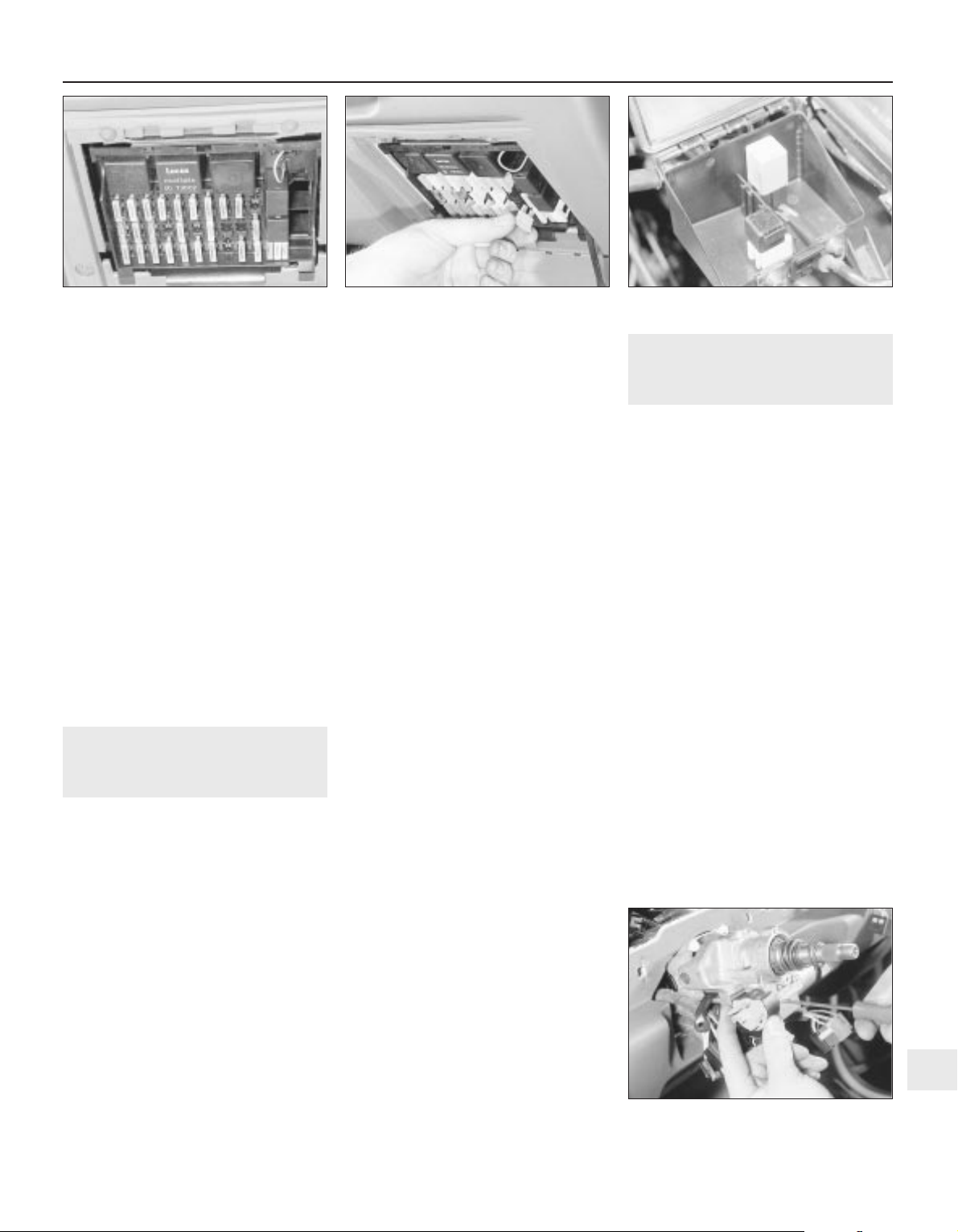
to-metal contact between components, due
to flexible rubber mountings, etc.
To check whether a component is properly
earthed, disconnect the battery, and connect
one lead of an ohmmeter to a known good
earth point. Connect the other lead to the wire
or earth connection being tested. The
resistance reading should be zero; if not,
check the connection as follows.
If an earth connection is thought to be
faulty, dismantle the connection, and clean
back to bare metal both the bodyshell and the
wire terminal or the component earth
connection mating surface. Be careful to
remove all traces of dirt and corrosion, then
use a knife to trim away any paint, so that a
clean metal-to-metal joint is made. On
reassembly, tighten the joint fasteners
securely; if a wire terminal is being refitted,
use serrated washers between the terminal
and the bodyshell, to ensure a clean and
secure connection. When the connection is
remade, prevent the onset of corrosion in the
future by applying a coat of petroleum jelly or
silicone-based grease.
3 Fuses and relays — general
Fuses
1 Fuses are designed to break a circuit when
a predetermined current is reached, to protect
the components and wiring which could be
damaged by excessive current flow. Any
excessive current flow will be due to a fault in
the circuit, usually a short-circuit (Section 2).
2 The main fuses and relays are located in a
panel at the lower right-hand side of the facia,
under a hinged cover (see illustration).
3 The circuits protected by the various fuses
and relays are marked on the inside of the
panel cover.
4 A blown fuse can be recognised from its
melted or broken wire.
5 To remove a fuse, first ensure that the
relevant circuit is switched off. Then open the
cover and pull the relevant fuse or relay from the
panel (see illustration). If desired, the lower
end of the panel can be tilted forwards, after
releasing the retaining clips to improve access.
6 Before renewing a blown fuse, trace and
rectify the cause, and always use a fuse of the
correct rating. Never substitute a fuse of a
higher rating, or make temporary repairs using
wire or metal foil, as more serious damage or
even fire could result.
7 Spare fuses are provided in the blank
terminal positions in the fusebox.
8 Note that the fuses are colour-coded, see
Specifications. Refer to the wiring diagrams
for details of the fuse ratings and the circuits
protected.
Relays
9 A relay is an electrically operated switch,
which is used for the following reasons:
a) A relay can switch a heavy current
remotely from the circuit in which the
current is flowing, allowing the use of
lighter-gauge wiring and switch contacts.
b) A relay can receive more than one control
input, unlike a mechanical switch.
c) A relay can have a timer function — for
example, the intermittent wiper relay.
10 Most of the relays are located at the rear
of the main fusebox (remove the securing
screws and pull the fusebox forwards to
improve access). The rear wiper motor relay is
located in the tailgate, behind the tailgate trim
panel. On some models, additional engine-
related relays are located in the relay box
mounted on the left-hand side of the engine
compartment.
11 On certain models, additional relays are
located in a box at the left-hand rear of the
engine compartment (see illustration).
12 If a circuit or system controlled by a relay
develops a fault, and the relay is suspect,
operate the system. If the relay is functioning, it
should be possible to hear it “click” as it is
energised. If this is the case, the fault lies with
the components or wiring of the system. If the
relay is not being energised, then either the
relay is not receiving a main supply or a
switching voltage, or the relay itself is faulty.
Testing is by the substitution of a known good
unit, but be careful — while some relays are
identical in appearance and in operation, others
look similar but perform different functions.
13 To remove a relay, first ensure that the
relevant circuit is switched off. The relay can
then simply be pulled out from the socket,
and pushed back into position.
4 Ignition switch and lock
cylinder — removal and
refitting
3
Removal
1 Disconnect the battery negative lead.
2 Turn the steering wheel as necessary to
expose the two front steering column shroud
securing screws, which are covered by plastic
caps. Prise out the caps and remove the
screws.
3 Remove the three securing screws from the
underside of the lower column shroud, then
remove both the upper and lower shrouds.
4 To remove the lock cylinder, insert the
ignition key and turn it to position “II”.
5 Insert a thin rod into the hole in the lock
housing, then press the rod to release the
detent spring, and pull out the lock cylinder
using the key.
6 The ignition switch is secured to the
steering lock housing by two grub screws.
Disconnect the wiring plug, and remove the
screws to extract the switch (see illustration).
Removal of the steering wheel, may aid
removal. Refer to Chapter 10 or Section 57, as
applicable. It is recommended that the switch
and the lock cylinder are not both removed at
the same time, so that their mutual alignment
is not lost.
Refitting
7 Refitting is a reversal of removal.
Body electrical systems 12•3
3.11 Relays in engine compartment box —
2.0 litre SRi model shown
4.6 Removing an ignition switch securing
screw
3.5 Removing a fuse —
2.0 litre model shown
3.2 Main fuses and relays in facia panel —
2.0 litre SRi model shown
12
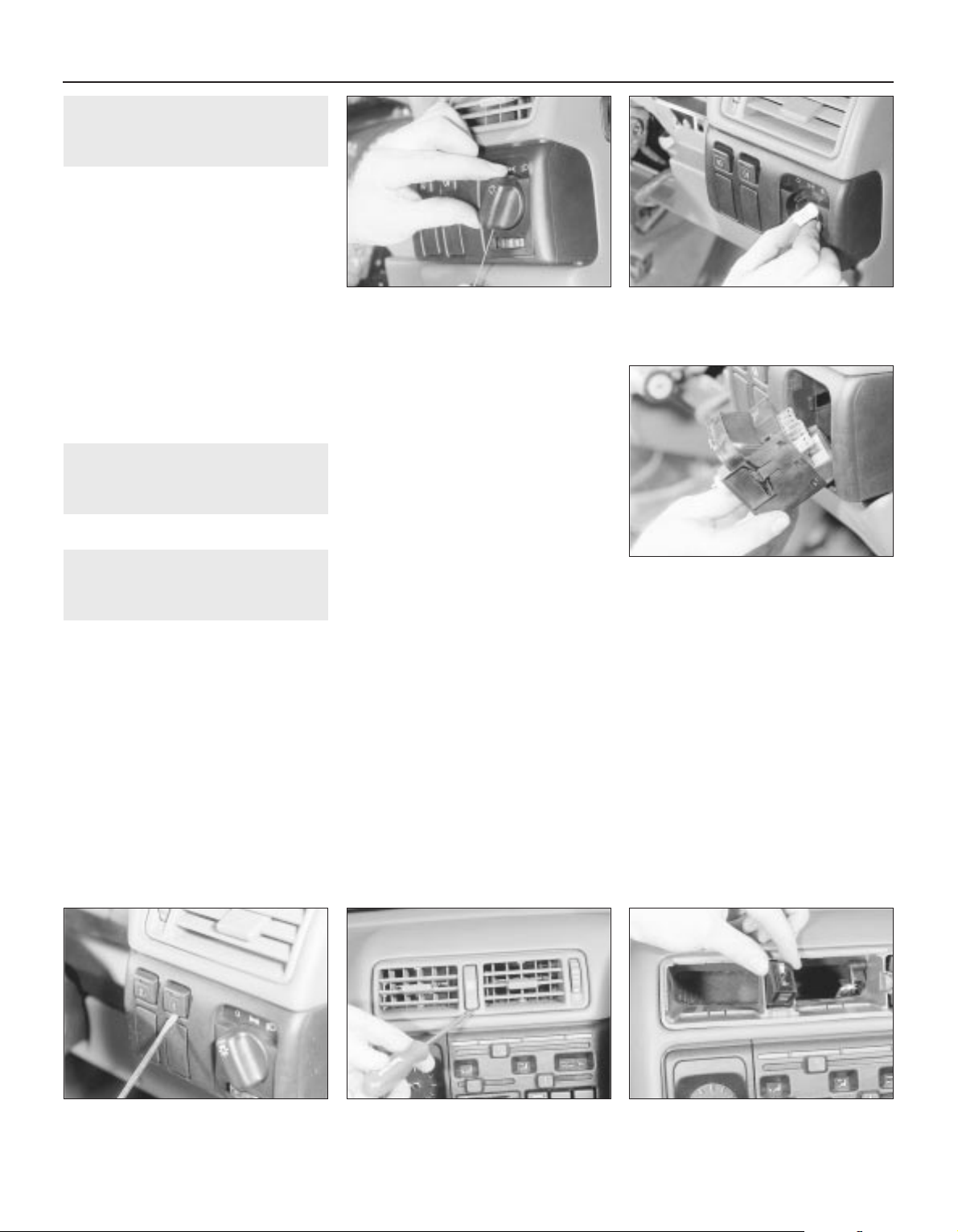
5 Direction indicator/lighting
switch — removal and refitting
2
Removal
1 Disconnect the battery negative lead.
2 Turn the steering wheel as necessary to
expose the two front steering column shroud
securing screws, which are covered by plastic
caps. Prise out the caps and remove the
screws.
3 Remove the three securing screws from the
underside of the lower column shroud, then
remove both the upper and lower shrouds.
4 Disconnect the wiring plug from the switch.
5 Depress the switch retaining clip, and
withdraw the switch from the housing.
Refitting
6 Refitting is a reversal of removal.
6 Wash/wipe switch — removal
and refitting
2
Proceed as described in Section 5.
7 Facia panel switches —
removal and refitting
2
1 Disconnect the battery negative lead.
Lighting switch
Removal
2 Turn the switch to the “dipped beam on”
position, then insert a small screwdriver or rod
through the hole in the bottom of the switch
knob to depress the knob retaining clip. Pull
the knob from the switch (see illustration).
3 Press the two now-exposed switch
securing clips towards the switch spindle,
then pull the switch from the facia and
disconnect the wiring plug (see illustrations).
4 Note that the switch assembly cannot be
dismantled, and if any part of the switch is
faulty, the complete assembly must be
renewed.
Refitting
5 Refitting is a reversal of removal.
Push-button switches
Removal
6 First check beneath the switch, if there is a
small hole in the facia, insert a slim
screwdriver or metal rod into it. Release the
switch retaining spring clip by pressing it
upwards against the switch, then remove the
switch and disconnect its wiring. If there is no
hole, remove the switch by prising it out of the
facia using a small screwdriver. Lever gently
under the switch’s lower edge (use adhesive
tape or a piece of card to protect the facia’s
finish). Disconnect the switch wiring plug and
withdraw the switch (see illustration).
Refitting
7 Refitting is a reversal of removal.
Headlamp aim adjustment
switch
8 The procedure is as described for push-
button switches.
Hazard warning switch
Removal
9 Using a screwdriver, carefully prise the cap
from the switch (see illustration).
10 Using a screwdriver with a piece of card
under the blade to avoid damage to the facia
trim, prise the ventilation nozzle from the
facia.
11 Prise the switch from the facia and
disconnect the wiring (see illustration).
Refitting
12 Refitting is a reversal of removal.
Heater blower motor switch
Removal
13 Remove the heater control panel, as
described in Chapter 11.
14 Disconnect the wiring plug from the
switch, if not already done.
15 Prise the switch out from the rear of the
heater control panel.
Refitting
16 Refitting is a reversal of removal, but refer
to Chapter 11, when refitting the heater
control panel.
12•4 Body electrical systems
7.2 Using a thin rod to depress the
lightning switch knob retaining clip
7.3B . . . then pull the switch from the facia
7.11 Withdrawing the hazard warning
flasher switch from the facia
7.9 Prising the cap from the hazard
warning flasher switch
7.6 Prising a push-button switch from the
facia
7.3A Press the switch securing clips
towards the switch spindle . . .
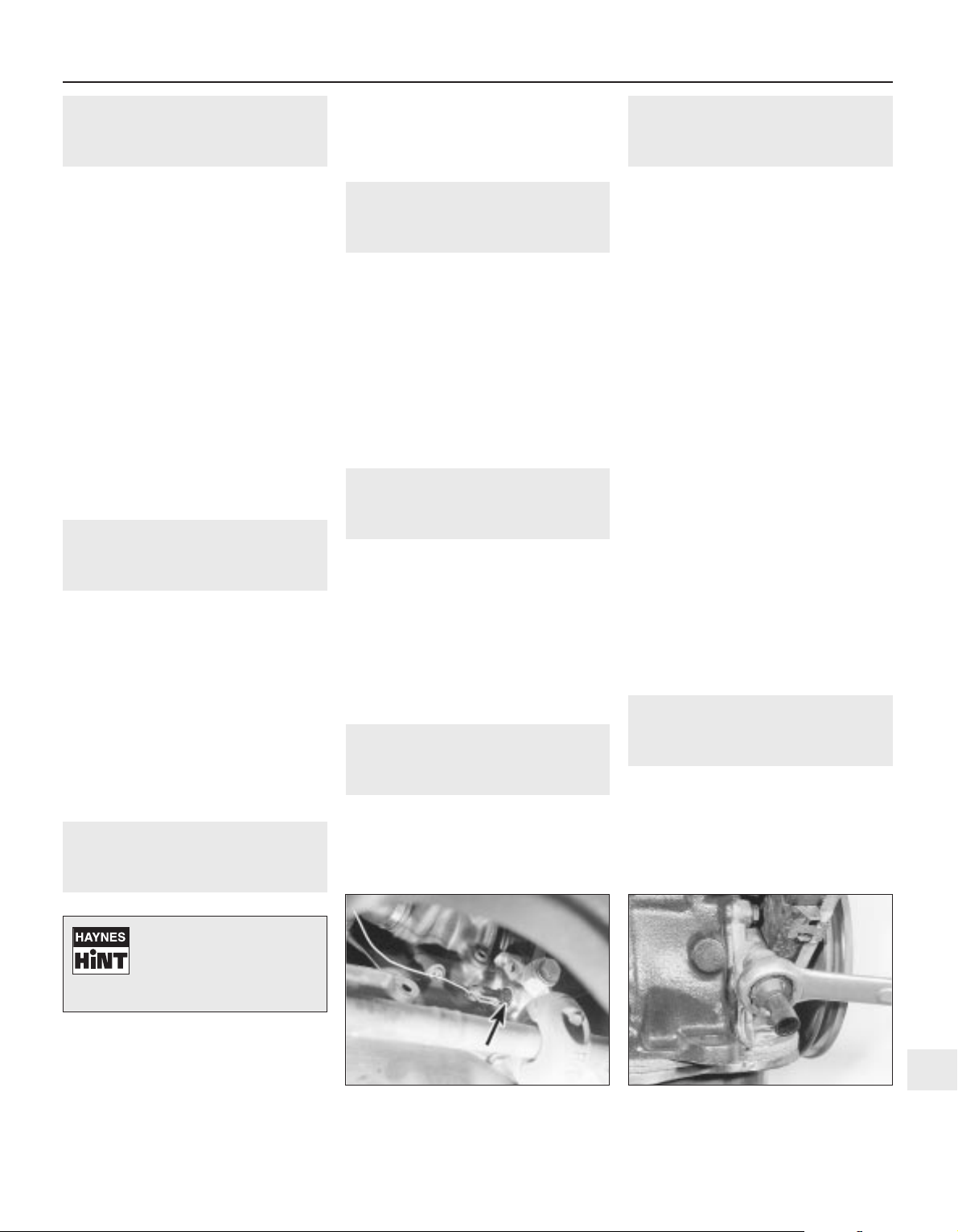
8 Electric door mirror switch —
removal and refitting
2
Removal
1 Disconnect the battery negative lead.
2 Prise the plastic surround from the door
interior handle.
3 Free the trim panel from the top edge of the
door by releasing the securing clips. This can
be done using a screwdriver, but it is
preferable to use a forked tool, to minimise
the possibility of damage to the trim panel and
the clips.
4 Note the position of the mirror switch wiring
connector in the bracket at the top of the
door, then separate the two halves of the
connector.
5 Prise the switch from the door trim panel,
and feed the wiring through the panel.
Refitting
6 Refitting is a reversal of removal, but ensure
that the wiring is correctly routed, so as not to
foul the door interior handle mechanism.
9 Sunroof operating switch —
removal and refitting
2
Removal
1 Disconnect the battery negative lead.
2 Prise the courtesy lamp from the roof trim
panel, and disconnect the wiring.
3 Remove the two trim panel securing
screws, and withdraw the trim panel from the
roof, disconnecting the wiring from the
sunroof operating switch.
4 Release the securing clips, then pull the
switch from the rear face of the trim panel.
Refitting
5 Refitting is a reversal of removal.
10 Courtesy lamp switch —
removal and refitting
2
Removal
1 Disconnect the battery negative lead.
2 Open the door and remove the switch
securing screw.
3 Withdraw the switch from the door pillar,
and pull the wiring out sufficiently to prevent it
from springing back into the pillar.
4 Disconnect the wiring and remove the
switch.
Refitting
5 Refitting is a reversal of removal.
11 Luggage compartment lamp
switch — removal and refitting
2
Removal
1 Disconnect the battery negative lead.
2 Open the boot lid or tailgate, as applicable,
and remove the switch securing screw.
3 Withdraw the switch from the body panel,
and pull the wiring out sufficiently to prevent it
from springing back into the body.
4 Disconnect the wiring and remove the
switch.
Refitting
5 Refitting is a reversal of removal.
12 Brake lamp switch — removal
and refitting
2
Removal
1 Disconnect the battery negative lead.
2 Remove the lower trim panel from the
driver’s footwell.
3 Disconnect the wiring plug from the brake
lamp switch, then twist the switch
anti-clockwise and remove it from its bracket.
Refitting
4 Refitting is a reversal of removal.
13 Handbrake “on” warning
lamp switch — removal and
refitting
3
For access to the switch, the handbrake
lever must be removed. Removal and refitting
of the switch is described as part of the
handbrake lever removal and refitting
procedure, in Chapter 9.
14 Oil pressure warning lamp
switch — removal and refitting
3
Removal
1 Disconnect the battery negative lead.
2 The switch is screwed into the oil pump, on
the inlet manifold side of the engine. On 1.4
and 1.6 litre (except C16 NZ2), models the
switch projects at right-angles to the
crankshaft axis, while on C16 NZ2, 1.8 and
2.0 litre models it is parallel to the crankshaft
(see illustration).
3 In most cases the switch can be reached
quite easily from above. However, on some
models access will be easier if the front of the
vehicle is jacked up and supported on axle
stands (see “Jacking and Vehicle Support”)
(ensure that the handbrake is securely
applied) and the front right-hand roadwheel is
removed.
4 Disconnect the switch wire and use a
spanner to unscrew the switch (see
illustration). As you withdraw the switch,
swiftly plug the hole in the oil pump to
minimise the loss of oil and to prevent the
entry of dirt.
Refitting
5 Refitting is the reverse of the removal
procedure; tighten the switch securely but do
not overtighten it, reconnect its wire, then
check and if necessary top-up the oil level, as
described in Chapter 1. Wash off any spilt oil
and check for leaks when the engine is
restarted.
15 Cigarette lighter — removal
and refitting
2
Removal
1 Disconnect the battery negative lead.
2 Slide the ashtray/cigarette lighter assembly
from the facia, then disconnect the wiring and
slide the illumination bulb from the cigarette
lighter.
Body electrical systems 12•5
14.4 Unscrewing the oil pressure warning
lamp switch —
SOHC model (engine removed)
14.2 Oil pressure warning lamp switch
(arrowed) viewed from underneath vehicle
— SOHC model
12
Tape the wiring to the door
pillar, to prevent if falling
back into the door pillar.
Alternatively, tie a piece of
string to the wiring to retrieve it.

3 To remove the cigarette lighter assembly,
simply pull it from the illumination ring
assembly. If desired, the illumination ring
assembly can be removed, by pulling it from
the housing after depressing the retaining
clips.
Refitting
4 Refitting is a reversal of removal.
16 Clock — removal and refitting
2
Removal
1 Disconnect the battery negative lead.
2 Using a thin-bladed screwdriver, carefully
prise the clock from the facia panel.
3 Disconnect the wiring plugs and withdraw
the clock (see illustration).
Refitting
4 Refitting is a reversal of removal.
17 Heated front seats — general
2
Heating pads are fitted to the front seats of
some models. Before attempting to remove a
seat so equipped, disconnect the battery and
the leads from the heating pad.
18 Instrument panel — removal
and refitting
3
Removal
1 Disconnect the battery negative lead.
2 Remove the steering wheel, (Chapter 10).
3 Remove the steering column shrouds, and
the instrument panel upper and lower trim
panels, (Chapter 11).
4 Remove the single upper, and two lower,
instrument panel securing screws (see
illustration).
5 Carefully withdraw the instrument panel,
and disconnect the speedometer cable and
the two wiring plugs. Note that the
speedometer cable is retained by a clip, which
must be pressed towards the speedometer to
release the cable (see illustration).
6 If desired, the instrument panel can be
dismantled, with reference to Section 19.
Refitting
7 Refitting is a reversal of removal, but ensure
that the speedometer cable is not kinked or
twisted between the instrument panel and the
bulkhead as the panel is refitted.
19 Instrument panel
components — removal and
refitting
3
1 With the instrument panel removed, as
described in Section 18, continue as follows.
Panel illumination and warning
lamp bulbs
Removal
2 Twist the relevant bulbholder clockwise,
and withdraw it from the printed circuit board
on the rear of the instrument panel (see
illustration).
3 The bulbs are integral with the bulbholders,
and must be renewed as a unit.
Refitting
4 Refitting is a reversal of removal.
Voltage stabiliser
Removal
5 Remove the single securing screw from the
rear of the instrument panel, then pull the
voltage stabiliser from the contacts on the
printed circuit board (see illustration).
Refitting
6 Refitting is a reversal of removal.
Fuel and temperature gauges —
“low series” models
Removal
7 Pull the trip meter reset pin from the front of
the panel.
8 Release the two retaining clips at the top of
the panel, and remove the panel shroud (see
illustration).
9 Unscrew the two securing nuts, and
withdraw the relevant gauge through the front
of the instrument panel.
12•6 Body electrical systems
16.3 Disconnecting the wiring plugs from
the clock
18.5 Disconnecting an instrument panel
wiring plug. Note speedometer cable
retaining clip (arrowed)
19.8 Removing the instrument panel
shroud
19.5 Instrument panel voltage stabiliser
(arrowed)
19.2 Withdrawing an instrument panel
illumination lamp bulb
18.4 Unscrewing a lower instrument panel
securing screw
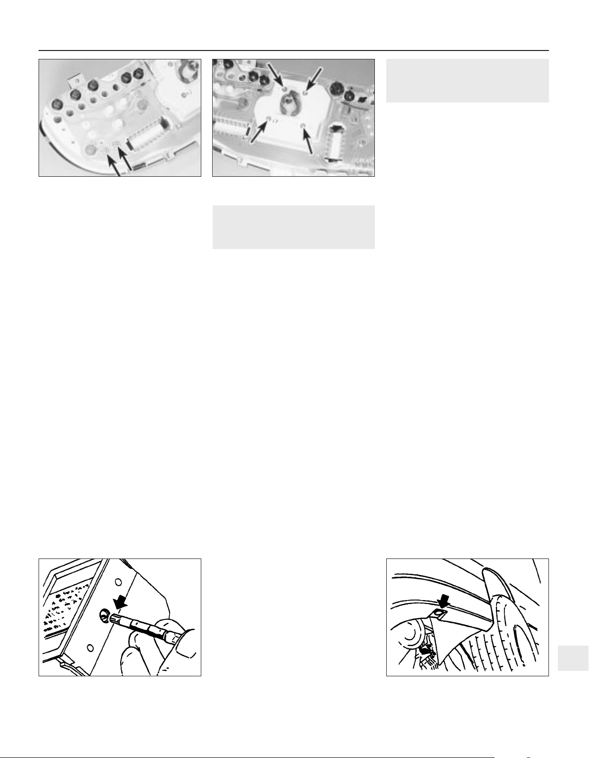
Refitting
10 Refitting is a reversal of removal.
Fuel and temperature gauge
assembly — “high series” models
11 The procedure is as described in
paragraphs 7 to 10 inclusive, except that the
gauge assembly is secured by four nuts.
Tachometer
12 The procedure is as described in
paragraphs 7 to 10 inclusive except that the
tachometer is secured by three nuts (see
illustration).
Speedometer
Removal
13 Proceed as described in paragraphs 7
and 8.
14 Extract the four securing screws from the
rear of the panel (see illustration).
Refitting
15 Refitting is a reversal of removal.
Printed circuit board
Removal
16 Remove all bulbs and instruments, and
the voltage stabiliser, as described previously
in this Section.
17 Carefully peel the printed circuit board
from the instrument panel.
Refitting
18 Refitting is a reversal of removal, but
ensure that the printed circuit board is seated
correctly on the rear of the instrument panel.
20 Trip computer components —
removal and refitting
2
1 Disconnect the battery lead.
Display module
Removal
2 Using a thin-bladed screwdriver, carefully
prise the module from the facia panel.
3 Disconnect the wiring plug and withdraw
the module.
Refitting
4 Refitting is a reversal of removal.
Display module illumination bulb
Removal
5 Remove the display module, as described
previously in this Section.
6 Using a length of rubber sleeving of similar
diameter, or an alternator tool, extract the
bulb by inserting the tool through the hole in
the side of the display module (see
illustration).
Refitting
7 Refitting is a reversal of removal.
Operating switch
Removal
8 Remove the rear section of the centre
console, as described in Chapter 11.
9 Release the wiring plug from the switch
using a screwdriver.
10 Lift the switch, then pull it down and out
from the centre console.
Refitting
11 Refitting is a reversal of removal.
Outside air temperature sensor
Removal
12 The sensor is located at the left-hand end
of the front bumper (see illustration).
13 Prise the cover cap from the bumper, then
unclip the sensor, and disconnect the wiring
plug.
Refitting
14 Refitting is a reversal of removal.
21 Check control system
components — removal and
refitting
3
1 Disconnect the battery negative lead.
Warning lamp bulbs
2 The warning lamp bulbs are located in the
instrument panel, and removal and refitting
are described in Section 19.
Control module
Removal
3 The control module is located behind the
passenger side of the facia, above the
glovebox.
4 Remove the glovebox assembly, as
described in Chapter 11.
5 Disconnect the control module wiring plug,
then release the control module from its
mounting and withdraw the unit.
Refitting
6 Refitting is a reversal of removal.
Coolant level sensor
Removal
7 The coolant level sensor is integral with the
coolant expansion tank cap.
8 Disconnect the wiring from the top of the
cap, then unscrew the cap and withdraw it
from the expansion tank.
9 If faulty, the complete cap assembly must
be renewed.
Refitting
10 Refitting is a reversal of removal.
Washer fluid level sensor
Removal
11 The sensor is mounted in the side of the
fluid reservoir.
12 Disconnect the wiring from the sensor,
then unscrew the sensor from the fluid
reservoir. If the fluid level is above the level of
the sensor, be prepared for fluid spillage.
Refitting
13 Refitting is a reversal of removal.
Body electrical systems 12•7
20.6 Removing the trip computer display
module illumination bulb
20.12 Trip computer outside air
temperature sensor location (arrowed)
19.14 Speedometer securing screws
(arrowed)
19.12 Tachometer securing nuts (arrowed)
12
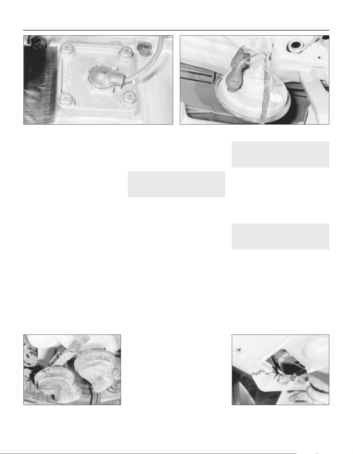
Brake fluid level sensor
14 The procedure is as described for the
coolant level sensor in paragraphs 7 to 10
inclusive.
Engine oil level sensor
Removal
15 Apply the handbrake, jack up the front of
the vehicle, and support securely on axle
stands (see “Jacking and Vehicle Support”)
positioned under the body side members.
16 On DOHC models, remove the engine
undershield, as described in Chapter 11.
17 Disconnect the sensor wiring plug.
18 Unscrew the three or four sensor securing
screws, as applicable, and withdraw the
sensor, manipulating the float through the hole
in the sump (see illustration). Recover the
sealing ring. Be prepared for some oil spillage.
19 Examine the condition of the sealing ring,
and renew if necessary.
Refitting
20 Refitting is a reversal of removal. On
completion, check, and if necessary top-up,
the engine oil level.
Bulb failure sensor
Removal
21 The bulb failure sensor is mounted behind
the fuse/relay panel in the facia.
22 Release the retaining clips from the lower
end of the fuse/relay panel, and tilt it forwards.
23 Reach up behind the fuse/relay panel, and
pull the sensor from its socket.
Refitting
24 Refitting is a reversal of removal.
22 Horn(s) — removal and refitting
2
1 On models with a single horn, the horn is
located in front of the radiator. On models
with twin horns, the horns are located beneath
the washer fluid reservoir, at the left-hand end
of the front bumper.
Single horn
Removal
2 Disconnect the battery negative lead.
3 Remove the radiator grille panel, with
reference to Chapter 11.
4 Disconnect the wiring from the rear of the
horn.
5 Reach up behind the mounting bracket, and
unscrew the single nut securing the horn to the
bracket (see illustration). Withdraw the horn.
Refitting
6 Refitting is a reversal of removal.
Twin horns
Removal
7 Disconnect the battery negative lead.
8 Apply the handbrake, then jack up the front
of the vehicle, and support securely on axle
stands (see “Jacking and Vehicle Support”)
positioned under the body side members.
9 Remove the securing screws, and withdraw
the plastic cover (where fitted) from the
bumper/front wing to expose the horns.
10 Remove the bolt securing the horn
mounting bracket to the bracket below the
washer fluid reservoir (see illustration).
11 Withdraw the horns and disconnect the
wiring.
12 If desired, the horns can be unbolted from
the bracket.
Refitting
13 Refitting is a reversal of removal.
23 Interior lamps — removal and
refitting
2
Removal
1 Disconnect the battery negative lead.
2 Using a thin-bladed screwdriver, prise the
lamp from its location and disconnect the
wiring (see illustration).
Refitting
3 Refitting is a reversal of removal.
24 Interior lamp bulbs — renewal
1
1 Disconnect the battery negative lead.
Courtesy lamp
Note: Some later models are fitted with
courtesy lamps for the rear seat passengers,
as well as front.
Removal
2 Using a thin-bladed screwdriver, prise the
lamp from its location and disconnect the
wiring.
3 On models fitted with a courtesy lamp with
integral map reading lamps, the lens must be
levered from the housing for access to the
bulbs.
12•8 Body electrical systems
21.18 Engine oil level sensor — DOHC model
22.10 Horn mounting bracket securing
bolt (arrowed) — twin horned model
23.2 Withdrawing the courtesy lamp
22.5 Horn viewed from behind with radiator removed — single
horned model
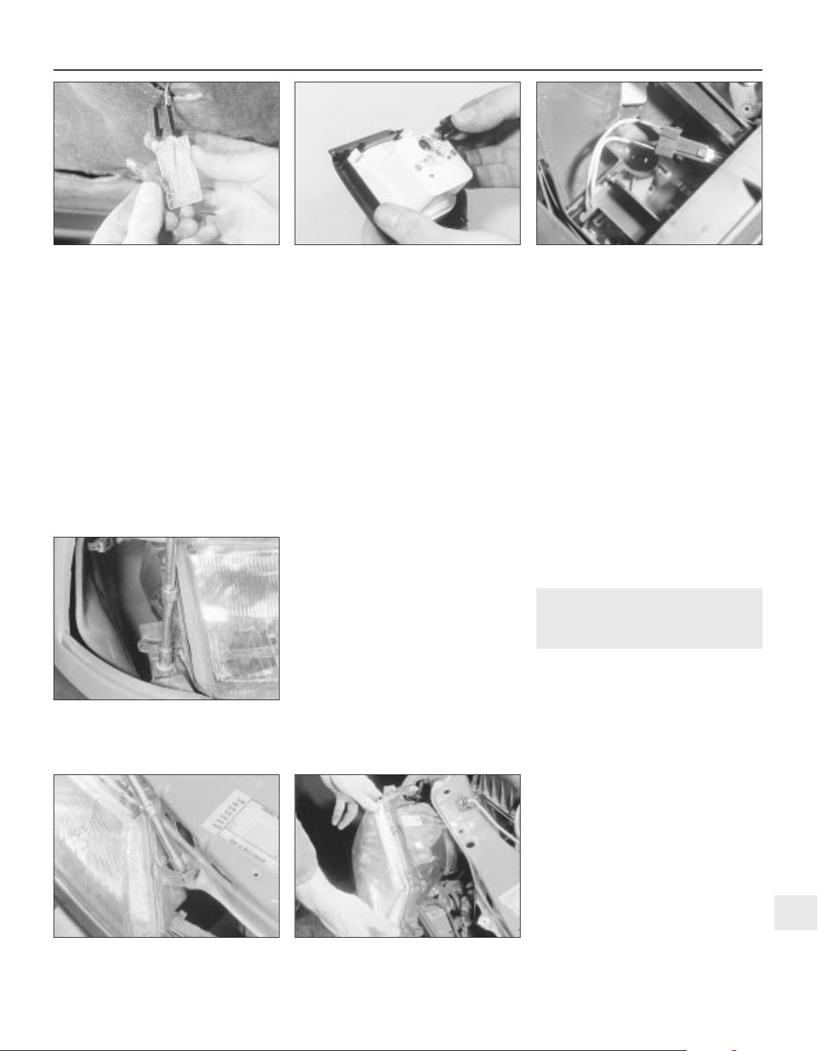
4 Remove the courtesy lamp bulbs by
carefully prising it from its location using a
thin-bladed screwdriver. Where applicable,
the map reading lamp bulbs are a push fit in
the bulbholders.
Refitting
5 Refitting is a reversal of removal.
Glovebox lamp
Removal
6 Using a thin-bladed screwdriver, prise the
lamp from its location and disconnect the
wiring.
7 Carefully prise the bulb from the lamp.
Refitting
8 Refitting is a reversal of removal.
Luggage compartment,
underbonnet and kerb lamps
Removal
9 Using a thin-bladed screwdriver, prise the
lamp from its location; disconnect the wiring.
10 Carefully prise the bulb from the lamp
(see illustration).
Refitting
11 Refitting is a reversal of removal
Cigarette lighter illumination lamp
Removal
12 Slide the ashtray/cigarette lighter
assembly from the facia, then disconnect the
wiring and pull the bulbholder from the rear of
the cigarette lighter housing.
13 The bulb is a push fit in the bulbholder.
Refitting
14 Refitting is a reversal of removal.
Clock illumination lamp
15 Remove the clock, (Section 16).
16 Twist the bulbholder and pull it from the
rear of the clock (see illustration).
17 The bulb is a push fit in the bulbholder.
Trip computer display module
illumination lamp
18 Refer to Section 20.
Heater control panel
illumination lamp
Removal
19 Remove the heater control panel, as
described in Chapter 11.
20 Pull the bulbholder from the rear of the
control panel (see illustration).
21 The bulb is a push fit in the bulbholder.
Refitting
22 Refitting is a reversal of removal.
Facia panel switch illumination
lamp
23 If a bulb fails in one of the facia panel
switches, the complete switch assembly must
be renewed, as described in Section 7, as no
individual spare parts are available.
Vanity mirror illumination lamp
Removal
24 Lower the sunvisor and, using a
thin-bladed screwdriver, prise out the mirror
and diffuser assembly. Pull the bulb(s) from
the spring contacts.
Refitting
25 Refitting is a reversal of removal.
25 Headlamp unit — removal and
refitting
2
Removal
1 Remove the radiator grille panel, as
described in Chapter 11.
2 Remove the front indicator lamp unit, as
described in Section 29.
3 Remove the cover from the rear of the
headlamp unit, and disconnect the wiring
plugs from the bulbs.
4 If applicable, disconnect the wiring plug
from the headlamp aim adjustment motor.
5 Remove the three securing screws, and
withdraw the headlamp unit (see
illustrations). Feed the wiring through the
headlamp casing as it is removed.
6 If required, the headlamp lens can be
removed by releasing the spring clips around
its edge.
Refitting
7 Refitting is a reversal of removal.
8 On completion, have the headlamp
alignment checked, with reference to
Section 27.
Body electrical systems 12•9
24.20 Heater control panel illumination
lamp bulbholder withdrawn
25.5C Withdrawing a headlamp unit25.5B Unscrewing an upper headlamp
securing screw
25.5A Unscrewing the lower headlamp
securing screw
24.16 Removing the clock illumination
lamp bulbholder
24.10 Removing the underbonnet lamp
bulb
12
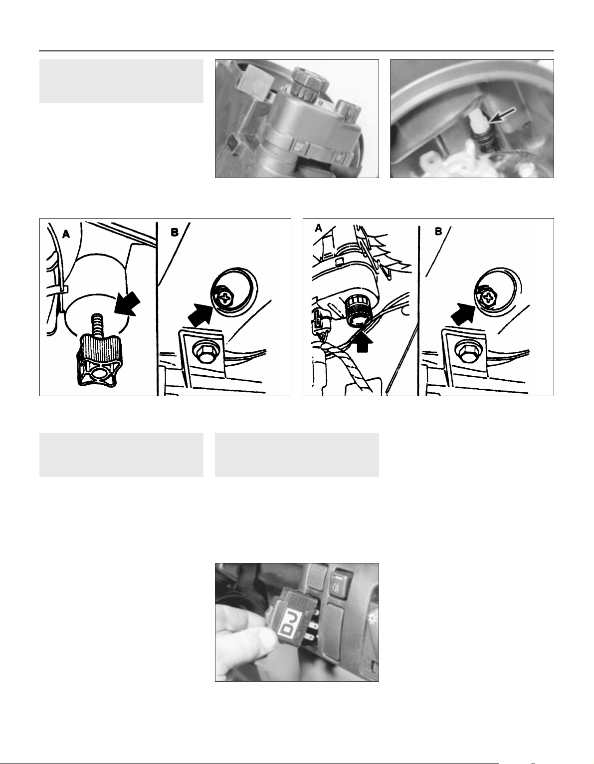
27 Headlamps — alignment
2
1 Correct alignment of the headlamp beams
is most important, not only to ensure good
vision for the driver, but also to protect other
drivers from being dazzled.
2 Accurate alignment should be carried out
using optical beam setting equipment.
3 In an emergency, adjustments may be
made by turning the adjustment screws
shown (see illustrations). If an adjustment is
made, the alignment should be checked using
beam setting equipment at the earliest
opportunity.
4 All 1992-on models are fitted with the
headlamp aim adjustment system, operated
through the facia-mounted switch (see
illustration).
a) Position ‘0’, is for correct alignment if just
the driving seat is occupied.
b) Position ‘1’, if all seats are occupied.
c) Position ‘2’, if all seats occupied and
luggage.
d) Position ‘3’, for just driver and luggage.
28 Headlamp dim-dip system —
general, removal and refitting
3
General
1 The system (where fitted) is governed by the
dim-dip control unit mounted either behind
and above the glovebox (early models), or
behind the main fuse panel (later models).
2 The control unit uses the oil pressure
warning lamp circuit to ensure that, when the
engine is running and the sidelamps are
switched on, reduced current is fed to the
headlamp dipped-beam circuits. This lights
the headlamps with approximately one-sixth
of their normal power so that the vehicle
cannot be driven using sidelamps alone.
3 To locate the dim-dip control unit, open the
main fuse panel covering flap and unclip it
from its bottom and top mountings (Section 3).
Then use a torch to see whether the unit is
fastened to the plastic bracket behind the facia
and fuse panel. The unit is usually rectangular,
of black plastic, and can be identified by the
colours of the five wires leading to it (see
applicable wiring diagram).
Removal
4 If the unit can be seen, remove the driver’s
side lower facia and footwell trim panels
(Chapter 11), then unscrew the four retaining
screws and lower the plastic bracket until the
control unit can be detached.
5 If the unit cannot be seen, remove the
glovebox assembly (Chapter 11). The unit will
be fastened to the underside of the facia top
surface.
Refitting
6 Refitting is the reverse of the removal
procedure.
26 Headlamp aim adjustment
motor — removal and refitting
3
Removal
1 Remove the headlamp, (Section 25).
2 Twist the motor clockwise to release it from
the headlamp, then carefully disconnect the
motor from the balljoint (see illustrations).
Refitting
3 Refitting is a reversal of removal, but ensure
that the motor is correctly engaged with the
balljoint.
12•10 Body electrical systems
26.2A Headlamp aim adjustment motor
(headlamp removed)
27.4 The headlamp aim adjustment switch
— 1992-on models
27.3B Headlamp alignment adjustment screws — models with
electric aim adjustment
A Vertical adjustment screw B Horizontal adjustment screw
27.3A Headlamp alignment adjustment screws — models without
electric aim adjustment
A Vertical adjustment screw B Horizontal adjustment screw
26.2B Headlamp aim adjuster balljoint
(arrowed)
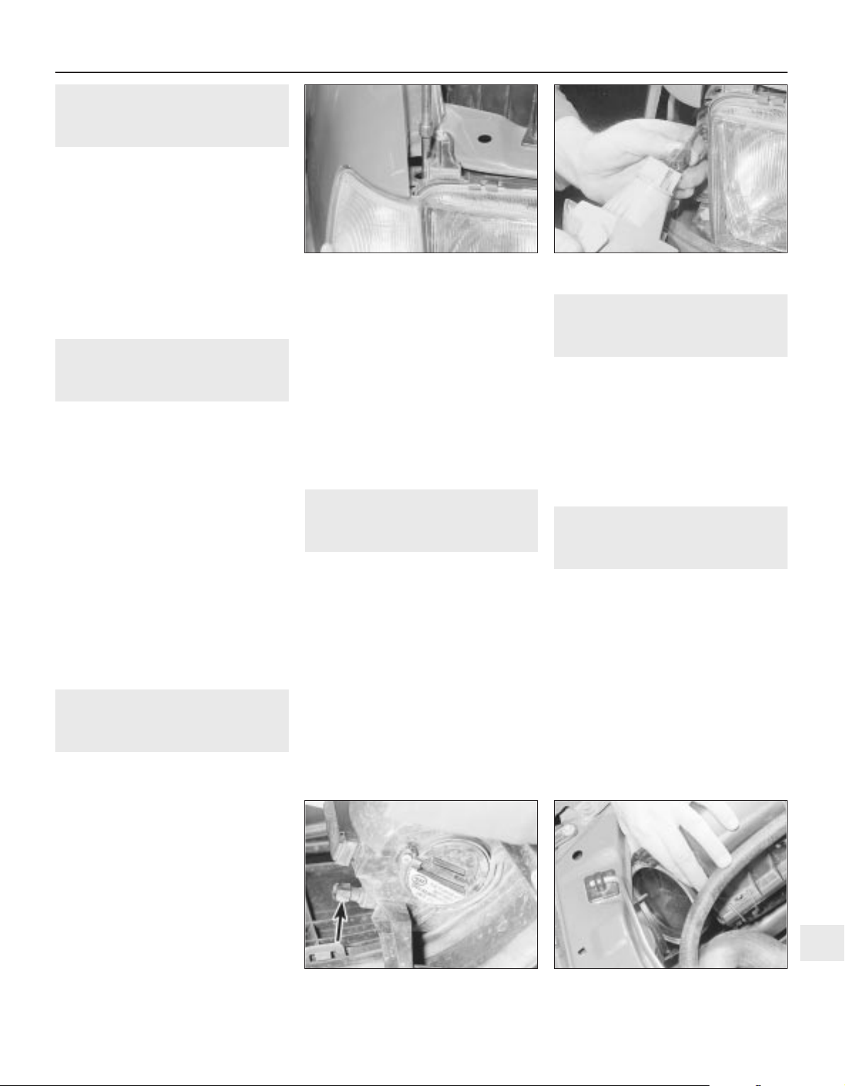
29 Front indicator lamp unit —
removal and refitting
2
Removal
1 Disconnect the battery negative lead.
2 Remove the single indicator lamp unit
securing screw, which is accessible through
the hole in the upper body panel (see
illustration).
3 Pull the lamp unit forwards to release it
from the body, then disconnect the wiring
plug (see illustration).
Refitting
4 Refitting is a reversal of removal.
30 Side repeater lamp — removal
and refitting
2
Removal
1 Disconnect the battery negative lead.
2 Remove the wheel arch liner, as described
in Chapter 11.
3 Working in the engine compartment,
disconnect the wiring plug, and detach the
earth lead from the body panel.
4 Working under the wheel arch, depress the
retaining tabs and manipulate the lamp
through the outside of the wing, pulling the
wiring and the grommet from the inner wing
panel.
5 The lens can be removed from the lamp by
twisting it to release the retaining clips.
6 Check the condition of the rubber sealing
ring, and renew if necessary.
Refitting
7 Refitting is a reversal of removal.
31 Front foglamp — removal,
refitting and adjustment
3
Removal
1 Disconnect the battery negative lead.
2 Removing (if necessary) the radiator grille
panel, as described in Chapter 11, disconnect
the appropriate foglamp wiring plug.
3 Apply the handbrake, jack up the front of
the vehicle and support it securely on axle
stands (see “Jacking and Vehicle Support”)
positioned under the body side members.
4 If removing the driver’s side foglamp,
remove the securing screws and withdraw the
plastic cover from the bumper/front wing to
expose the lamp mountings.
5 Unscrew the three securing bolts and
withdraw the lamp and wiring, the two bottom
bolts are obvious, but the third is well hidden
at the top of the lamp.
Refitting
6 Refitting is a reversal of removal, but on
completion check the foglamp adjustment.
Adjustment
7 The vertical aim of the foglamps can be
adjusted by turning the adjuster screw at the
rear of the lamp in the required direction. It will
be necessary to remove the plastic cover
(driver’s side only) from the bumper/front wing
to expose the adjuster screw (see
illustration).
32 Rear lamp unit — removal and
refitting
2
Removal
1 Disconnect the battery negative lead.
2 Working in the luggage compartment,
remove the cover from the rear of the lamp.
3 Release the top and bottom retaining clips,
and pull the bulbholder from the lamp.
Disconnect the wiring plug.
4 Remove the securing screws, and withdraw
the lamp unit from outside the vehicle.
5 Note that the lens cannot be renewed
separately, and if damaged, the complete
lamp unit must be renewed.
Refitting
6 Refitting is a reversal of removal.
33 Number plate lamp — removal
and refitting
2
Removal
1 Disconnect the battery negative lead.
2 Using a thin-bladed screwdriver, carefully
prise the lamp surround from the bumper.
3 Pull the lamp from the bumper, and
disconnect the wiring.
Refitting
4 Refitting is a reversal of removal.
34 Exterior lamp bulbs — renewal
1
Note: The glass envelopes of the headlamp
and foglamp bulbs must not be touched with
the fingers. If the glass is accidentally
touched, it should be washed with methylated
spirits and dried with a soft cloth. Failure to
observe this procedure may result in
premature bulb failure
1 Disconnect the battery negative lead.
Headlamps
Removal
2 Working in the engine compartment,
release the retaining clip, and remove the
cover from the rear of the headlamp (see
illustration).
Body electrical systems 12•11
31.7 Foglamp aim adjustment screw
(arrowed)
34.2 Removing the cover from the rear of
the headlamp
29.3 Disconnecting the front indicator
lamp unit wiring plug
29.2 Unscrewing the front indicator lamp
unit securing screw
12
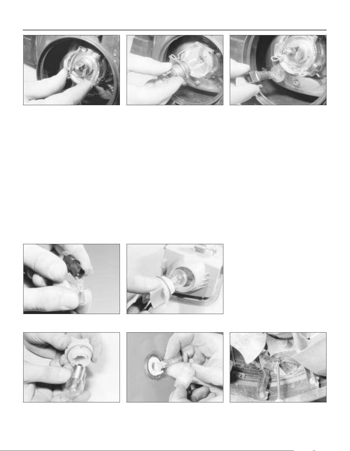
3 Pull the wiring plug from the base of the bulb,
then release the spring clip, grasp the bulb by
its contacts and carefully withdraw it (see
illustrations). Do not touch the bulb glass.
Refitting
4 Refitting is a reversal of removal.
Sidelamps
Removal
5 Working in the engine compartment,
release the retaining clip, and remove the
cover from the rear of the headlamp.
6 Pull the wiring plug from the bulbholder,
then pull the bulbholder from the headlamp
(see illustration).
7 The bulb is a push fit in the bulbholder (see
illustration).
Refitting
8 Refitting is a reversal of removal.
Front indicator lamp
Removal
9 Working in the engine compartment,
disconnect the wiring plug from the
bulbholder.
10 Twist the bulbholder anti-clockwise, and
pull it from the lamp unit (see illustration).
11 The bulb is a bayonet fit in the bulbholder
(see illustration).
Refitting
12 Refitting is a reversal of removal.
Front indicator side repeater
lamp
Removal
13 Twist the lamp lens anti-clockwise, and
pull it from the lamp.
14 The bulb is a push fit in the lamp (see
illustration).
Refitting
15 Refitting is a reversal of removal, but
ensure that the rubber sealing ring is correctly
seated between the lens and the body panel.
Front foglamp
Removal
16 To improve access, apply the handbrake,
jack up the front of the vehicle, and support
securely on axle stands (see “Jacking and
Vehicle Support”) positioned under the body
side members.
17 Remove the securing screws, and
withdraw the plastic cover (driver’s side only)
from the bumper/front wing to expose the
foglamp.
18 Remove the security screw, and withdraw
the cover from the base of the lamp (see
illustration).
19 Release the spring clip, using a
screwdriver if necessary, then grasp the bulb
by its contacts and carefully withdraw it. Do
not touch the bulb glass (see illustration).
20 Pull the wiring plug from the base of the
bulb.
Refitting
21 Refitting is a reversal of removal.
Rear lamp unit
Removal
22 Working in the luggage compartment,
remove the cover from the rear of the lamp.
23 Release the top and bottom retaining
clips, and pull the bulbholder from the lamp,
12•12 Body electrical systems
34.3A Release the spring clip . . . 34.6 Pull the sidelamp bulbholder from the
headlamp . . .
34.18 Removing a front foglamp cover
securing screw
34.10 Withdraw the front indicator lamp
bulbholder (lamp removed) . . .
34.07 . . . then pull the bulb from the
bulbholder
34.14 Removing a front indicator side
repeater lamp bulb
34.11 . . . then remove the bulb
34.3B . . . and withdraw the headlamp bulb
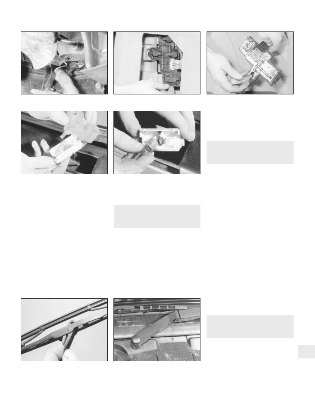
taking care not to strain the wiring (see
illustration).
24 The bulbs are a bayonet fit in the bulbholder
(see illustration). Note that the brake/tail lamp
bulb has offset bayonet pins so that it can only
be fitted in one position; ensure that the correct
type of replacement is obtained.
Refitting
25 Refitting is a reversal of removal.
Rear number plate lamp
Removal
26 Using a thin-bladed screwdriver, carefully
prise the lamp surround from the bumper.
27 Pull the lamp from the bumper, taking
care not to strain the wiring, and unclip the
lens (see illustration).
28 The bulb is a bayonet fit in the lamp (see
illustration).
Refitting
29 Refitting is a reversal of removal.
35 Wiper blades — renewal
1
Removal
1 The wiper blades should be renewed when
they no longer clean the glass effectively.
2 Lift the wiper arm away from the glass. On
some models it may be more convenient to do
this with the bonnet open.
3 With the blade at 90° to the arm, depress
the spring clip and slide the blade from the
hook (see illustration).
4 If necessary, extract the two metal inserts
and unhook the wiper rubber.
Refitting
5 Refitting is a reversal of removal, but where
applicable, make sure that the cut-outs in the
metal inserts securing the rubber to the blade
face each other.
36 Wiper arms — removal and
refitting
2
Windscreen and rear window
wipers
Removal
1 The wiper motor should be in its parked
position before removing the wiper arm. Mark
the position of the blade on the glass with
adhesive tape as a guide to refitting.
2 Lift the hinged covers, and remove the nuts
and washers securing the arms to the
spindles.
3 Prise the arms from the spindles, using a
screwdriver if necessary. Take care not to
damage the paintwork.
Refitting
4 Refitting is a reversal of removal. Note that
the passenger side wiper arm is longer than
that fitted to the driver’s side. Ensure that the
arms are fitted to their correct locations, as
incorrect installation can cause the blades to
foul one another when being used (see
illustration).
Headlamp wipers
5 The procedure is as described in
paragraphs 1 to 4, but the washer hose must
be disconnected from the stub on the body
panel.
37 Washer nozzles — removal
and refitting
1
Models up to 1990
Removal
1 To remove a nozzle, carefully prise it from
its location using a thin-bladed screwdriver.
Take care not to damage the paintwork.
Body electrical systems 12•13
34.24 . . . then remove the relevant bulb
36.4 Windscreen wiper arms —
1992-on models
35.3 Removing a wiper blade
34.28 . . . then remove the bulb34.27 Unclip the lens from the rear
number plate lamp . . .
34.23 Release the rear lamp unit
bulbholder retaining clips . . .
34.19 Withdrawing a foglamp bulb
12

2 Disconnect the washer hose and withdraw
the nozzle.
Refitting
3 To refit, reconnect the washer hose to the
nozzle, and push the nozzle into its locating
hole.
4 The nozzles can be adjusted by inserting a
pin into the jet, and swivelling it to the
required position.
1991-on models
5 The nozzles on all later models are fitted
with twin jets.
6 On some later models, the nozzles are
heated; the circuit is fed through fuse 29 and
is live whenever the ignition is switched on.
Current is regulated by a Positive
Temperature Coefficient (PTC) resistor that
takes outside temperature into account.
38 Windscreen wiper motor and
linkage — removal and refitting
3
Removal
1 Disconnect the battery negative lead.
2 Remove the wiper arms, as described in
Section 36.
3 Remove the windscreen cowl panel, as
described in Chapter 11.
4 Disconnect the wiring plug from the motor
(see illustration).
5 Unscrew the three bolts securing the
motor/linkage assembly to the body, then
withdraw the assembly (see illustrations).
6 If desired, the motor can be removed from
the linkage by unscrewing the three securing
bolts. Do not attempt to dismantle the linkage.
Refitting
7 Refitting is a reversal of removal.
39 Tailgate wiper motor —
removal and refitting
3
Removal
1 Disconnect the battery negative lead.
2 Remove the wiper arm, as described in
Section 36.
3 Extract the securing screws, and remove
the rear tailgate trim panel.
4 Disconnect the motor wiring plug.
5 Unscrew the two motor securing bolts,
noting the earth leads under the bolt heads
(see illustration).
6 Manipulate the motor assembly from the
tailgate.
Refitting
7 Refitting is a reversal of removal, ensuring
that the cut-out in the drive spindle rubber
seal engages with the notch in the drive
spindle (see illustration).
40 Headlamp wiper motor —
removal and refitting
3
Removal
1 Disconnect the battery negative lead.
2 Remove the wiper arm, as described in
Section 36.
3 Remove the headlamp, as described in
Section 25.
4 Disconnect the motor wiring plug.
5 Unscrew the two bolts securing the motor
mounting bracket to the body panel, then
withdraw the motor (see illustrations).
Refitting
6 Refitting is a reversal of removal.
12•14 Body electrical systems
38.4 Disconnecting the windscreen wiper
motor wiring plug
38.5B . . . then withdraw the assembly
40.5B . . . and withdraw the motor40.5A Unscrew the headlamp wiper motor
securing bolts . . .
39.7 Cut-out in tailgate wiper motor drive
spindle rubber seal must engage with
notch in drive spindle
39.5 Tailgate wiper motor assembly. Note
earth leads under heads of securing bolts
38.5A Unscrew the windscreen wiper
motor/linkage assembly securing bolts . .
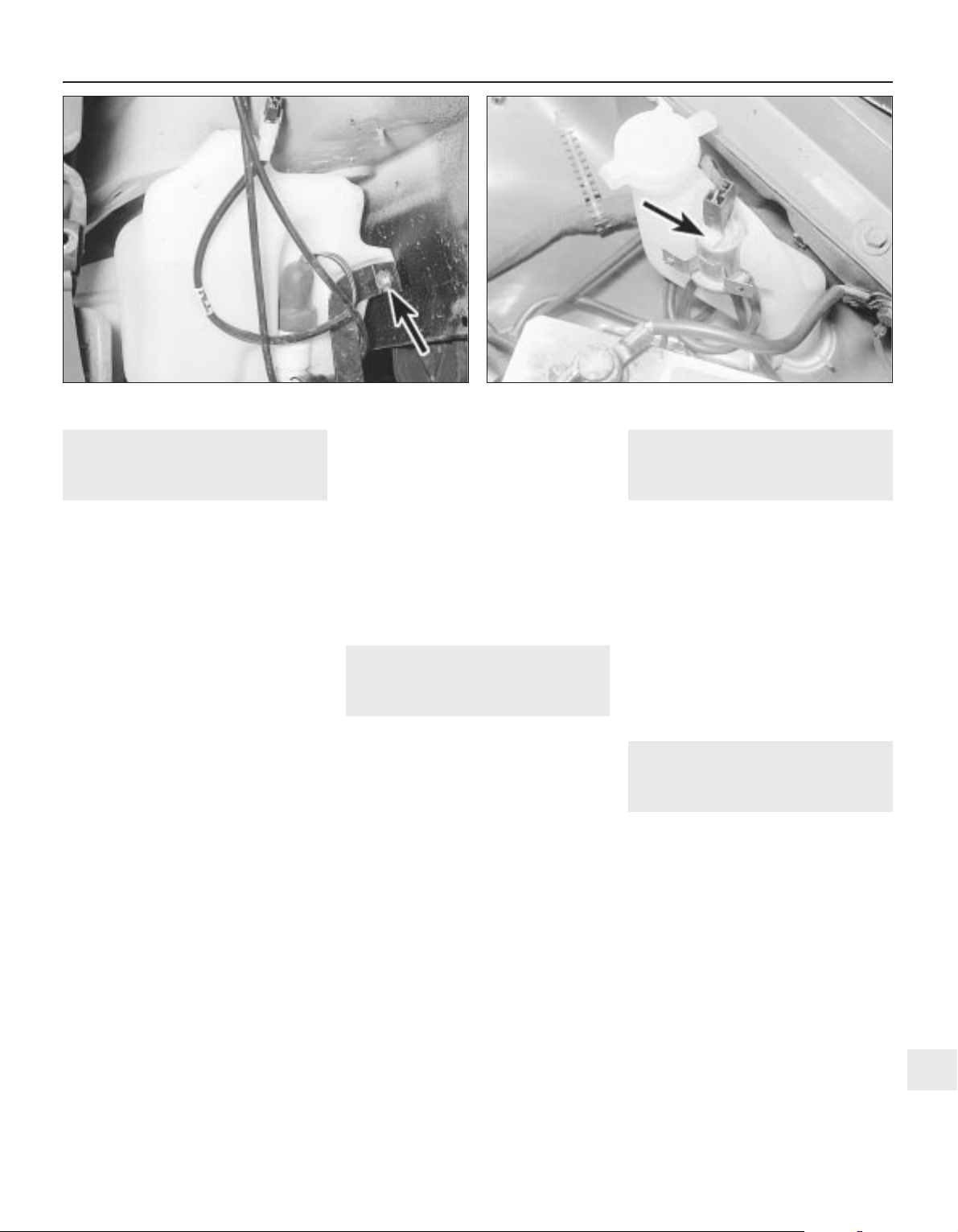
41 Washer fluid reservoir —
removal and refitting
2
1 Disconnect the battery negative lead.
Models without headlamp wash
Removal
2 Disconnect the wiring from the washer
pump.
3 Disconnect the washer fluid hose from the
pump. Be prepared for fluid spillage.
4 Remove the screw(s) securing the reservoir
to the body, and withdraw the reservoir.
Refitting
5 Refitting is a reversal of removal.
Models with headlamp wash
Removal
6 On models with headlamp wash, the
reservoir is in two sections, the upper section,
which can be removed from the engine
compartment, and the lower section, which
must be removed from under the wheel arch.
7 Disconnect the wiring from the headlamp
wash non-return valve in the top of the
reservoir.
8 Disconnect the washer fluid hoses from the
non-return valve. Be prepared for fluid spillage.
9 Remove the screw securing the upper
section of the reservoir to the wing panel.
10 Loosen the plastic collar securing the
upper section of the reservoir to the lower
section, then withdraw the upper section of
the reservoir from the engine compartment.
11 To remove the lower section of the
reservoir, continue as follows.
12 Apply the handbrake, then jack up the
front of the vehicle, and support on axle
stands (see “Jacking and Vehicle Support”)
positioned under the body side members.
13 Remove the securing screws, and
withdraw the plastic cover from the
bumper/front wing to expose the lower
section of the reservoir.
14 Remove the horns, (Section 22).
15 Remove the wheel arch liner, (Chapter 11).
16 Disconnect the wiring and the fluid hoses
from the washer pump. Be prepared for fluid
spillage.
17 Unscrew the bolts securing the
horn/reservoir support bracket and the
reservoir to the body, then withdraw the
bracket and the reservoir (see illustration).
Refitting
18 Refitting is a reversal of removal.
42 Washer pump — removal and
refitting
2
1 Disconnect the battery negative lead.
Models without headlamp wash
Removal
2 Disconnect the wiring and the fluid hose
from the pump. Be prepared for fluid spillage.
3 Pull the pump from the reservoir, being
prepared for fluid spillage if the reservoir still
contains fluid.
4 Examine the condition of the sealing
grommet, and renew if necessary, and clean the
gauze filter at the end of the pump pick-up tube.
Refitting
5 Refitting is a reversal of removal.
Models with headlamp wash
6 Apply the handbrake, then jack up the front
of the vehicle, and support on axle stands
positioned under the body side members.
7 Remove the securing screws, and withdraw
the plastic cover from the bumper/front wing
to expose the lower section of the fluid
reservoir.
8 Remove the wheel arch liner, (Chapter 11).
9 Proceed as described in paragraphs 2 to 5
inclusive.
43 Headlamp washer fluid
non-return valve — removal
and refitting
2
Removal
1 The valve is located on a bracket attached
to the upper section of the washer fluid
reservoir (see illustration).
2 Disconnect the battery negative lead.
3 Disconnect the wiring and the fluid hoses
from the valve. Be prepared for fluid spillage.
4 Remove the screw securing the valve
bracket to the reservoir, and withdraw the
valve.
Refitting
5 Refitting is a reversal of removal.
44 Electric window components
— removal and refitting
3
Note: Whenever any of the electric window
components are removed, after refitting the
components, the electric window controls
must be programmed, as described in
Section 45.
1 Disconnect the battery negative lead.
Rear door-mounted switches
Removal
2 Prise the plastic surround from the door
interior handle.
3 Carefully prise the switch from its location,
and disconnect the wiring plug.
Refitting
4 Refitting is a reversal of removal, but make
sure that the wiring is routed so that it does
not foul the electric window or lock operating
components.
Body electrical systems 12•15
43.1 Headlamp washer fluid non-return valve (arrowed)41.17 Horn/washer fluid reservoir support bracket securing bolt
(arrowed) — model with headlamp wash
12
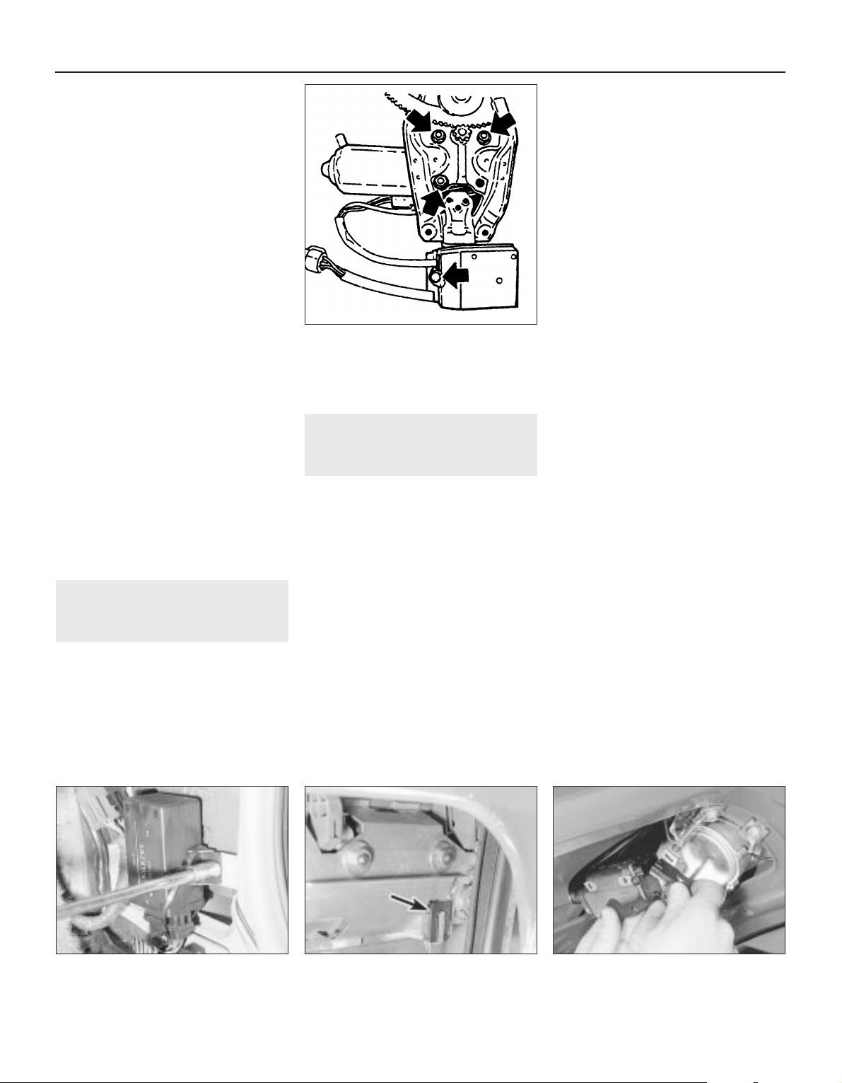
Centre console-mounted
switches
Removal
5 The switches must be removed as a
complete assembly, and cannot be
dismantled. If one of the switches is faulty, the
complete assembly must be renewed.
6 Remove the rear section of the centre
console, as described in Chapter 11.
7 Release the securing clips, and withdraw
the switch assembly through the top of the
centre console.
Refitting
8 Refitting is a reversal of removal.
Operating motors
9 Remove the door window regulator, as
described in Chapter 11.
10 To remove the motor assembly from the
front door window regulator, unscrew the
three motor securing nuts, and the single
screw securing the pulse pick-up unit to the
regulator assembly. Withdraw the motor,
complete with the pulse pick-up unit. Note
that if the motor or pick-up unit is/are faulty,
the two components must be renewed as an
assembly, as no spare parts are available (see
illustration).
11 The motor assembly fitted to the rear door
window regulator is an integral part of the
regulator, and no attempt should be made at
dismantling. If faulty, the complete
motor/regulator assembly must be renewed,
as no spares are available.
45 Electric window controls —
programming
1
1 Whenever the battery is disconnected, or any
of the electric window components are removed,
on completion of work, the electric window
controls must be programmed as follows.
2 Close all doors, and switch on the ignition.
3 Close one of the windows by pressing the
relevant operating switch. Press and hold the
switch for a further five seconds after the
relevant window has fully closed.
4 Repeat the procedure for the remaining
window(s).
46 Central door locking
components — removal and
refitting
3
1 Disconnect the battery negative lead.
Electronic control module
Removal
2 The module is mounted in the driver’s
footwell, behind the side trim panel.
3 Remove the driver’s footwell side trim
panel, as described in Chapter 11.
4 Unscrew the two securing nuts, and lift the
module from the body panel (see
illustration).
5 Depress the retaining clip to release the
wiring plug, then withdraw the module.
Refitting
6 Refitting is a reversal of removal.
Operating switch
Removal
7 The operating switch takes the form of a
microswitch, mounted inside the door at the
rear of the exterior handle assembly.
8 Remove the door inner trim panel, as
described in Chapter 11.
9 Peel back the plastic insulating sheet
sufficiently to gain access to the exterior
handle.
10 Unclip the microswitch from the rear edge
of the exterior handle assembly, and
disconnect the switch wiring plug from the
door wiring harness, then withdraw the switch
(see illustration).
Refitting
11 Refitting is a reversal of removal.
Door lock operating motor
Removal
12 Remove the door lock, as described in
Chapter 11.
13 Disconnect the lock operating rod from
the motor.
14 Remove the two securing screws, and
withdraw the motor from the lock assembly.
Refitting
15 Refitting is a reversal of removal.
Tailgate/boot lid lock operating
motor
Removal
16 On Hatchback models, extract the
securing screws and remove the rear tailgate
trim panel.
17 Remove the two securing screws, and
manipulate the motor to disconnect the lock
operating rod.
18 Withdraw the motor and disconnect the
wiring plug (see illustration).
Refitting
19 Refitting is a reversal of removal.
Fuel filler flap lock operating
motor
Removal
20 Remove the right-hand rear quarter trim
panels, as described in Chapter 11.
21 Disconnect the wiring plug from the rear
of the motor (see illustration).
12•16 Body electrical systems
44.10 Front door electric window motor
securing nuts and pulse pick-up securing
screw (arrowed)
46.10 Central door locking operating
microswitch (arrowed) in driver’s door
46.18 Disconnecting the wiring plug from
the tailgate lock operating motor —
Hatchback model
46.4 Unscrewing a central door locking
control module securing nut

22 Unscrew the two screws securing the
motor to the mounting bracket, then
manipulate the motor to disconnect the lock
operating rod. Withdraw the motor.
Refitting
23 Refitting is a reversal of removal.
47 Aerial — removal and refitting
3
Removal
1 On models with an electric aerial,
disconnect the battery negative lead.
2 Remove the left-hand rear quarter trim
panel, as described in Chapter 11.
3 Remove the screw securing the earth
lead(s) to the body panel (see illustration).
4 Remove the screw securing the aerial
bracket to the body panel, then ensure that
the aerial is fully retracted, and pull it through
the grommet in the bodywork into the luggage
compartment. Disconnect the wiring plug on
models with an electric aerial, and disconnect
the aerial lead (see illustrations).
Refitting
5 Refitting is a reversal of removal, but ensure
that the rubber grommet is correctly seated in
the bodywork.
48 Aerial mast, electric —
removal and refitting
3
Removal
1 The mast on “factory fitted”, fully automatic
electric aerials, can be replaced separately.
2 Extend the aerial as far as possible, by
switching on the radio.
3 Unscrew the mounting nut.
4 Pull the sprung sleeve upwards and clear of
its base.
5 The assembly can now be removed from
the clutch mechanism, by pulling the
assembly upwards.
Refitting
6 Insert the ball end of the mast assembly
into the base.
7 Carefully push the mast assembly down as
far as possible, until it engages into the clutch
mechanism (see illustration).
8 Switch the radio off to retract the aerial.
9 If the aerial does not fully retract into its
base, guide the remaining mast into the base
by hand.
10 Insert the sprung sleeve into the base and
tighten the mounting nut.
11 Check the aerial works properly by turning
the radio on and off a few times.
49 Speakers — removal and
refitting
2
1 Disconnect the battery negative lead.
Facia-mounted speaker
Removal
2 Using a thin-bladed screwdriver, carefully
prise the speaker from the top of the facia
panel. Take care not to damage the facia trim
(see illustration)
3 Disconnect the wiring and withdraw the
speaker. If desired, the plastic trim panel can
be unclipped from the top of the speaker.
Refitting
4 Refitting is a reversal of removal.
Front door-mounted speaker
Removal
5 Remove the door inner trim panel, as
described in Chapter 11.
Body electrical systems 12•17
47.4A Unscrewing the radio aerial bracket
securing screws — electric aerial
49.2 Removing a facia-mounted speaker
(viewed through windscreen)
48.7 Push the mast assembly down, until it
engages in the clutch mechanism
47.4B Disconnecting the aerial lead —
electric aerial
47.3 Radio aerial earth lead securing
screw (arrowed) — electric aerial
46.21 Disconnecting the wiring plug from
the fuel filler flap operating motor —
Hatchback model
12
Always clean the aerial mast
in an upwards direction. This
should minimise dirt being
forced down, into the mast
sections.
Always clean the aerial mast
in an upwards direction. This
should minimise dirt being
forced down, into the mast
sections.

6 Remove the three securing screws, and
withdraw the speaker from the door.
Disconnect the wiring plug (see illustration).
Refitting
7 Refitting is a reversal of removal, but note
that the speaker can only be fitted one way
up, so that the lug on the bottom of the
speaker rim engages with the corresponding
hole in the door skin.
Rear speaker — Hatchback
models
Removal
8 Remove the upper rear quarter trim panel,
as described in Chapter 11.
9 Remove the four securing screws, and
withdraw the speaker.
Refitting
10 Refitting is a reversal of removal.
Rear speaker Saloon models
Removal
11 Carefully prise the trim cover from the
parcel shelf, to expose the speaker.
12 Remove the four securing screws,
withdraw the speaker and disconnect the
wiring.
Refitting
13 Refitting is a reversal of removal.
50 Radio/cassette player —
removal and refitting
2
Removal
1 All the radio/cassette players fitted to the
Cavalier range have DIN standard fixings. Two
special tools, obtainable from in-car
entertainment specialists, are required for
removal.
2 Disconnect the battery negative lead.
3 Unscrew the four grub screws from the
corners of the radio cassette player, using an
Allen key or hexagon bit (see illustration).
4 Insert the tools into the holes exposed by
removal of the grub screws, and push them
until they snap into place. Pull the tools
outwards to release the unit (see illustration).
5 Pull the unit forwards, and withdraw it from
the facia.
Refitting
6 To refit the radio/cassette player, simply
push the unit into the facia until the retaining
lugs snap into place, then refit the grub
screws.
51 Sunroof motor — removal and
refitting
3
Removal
1 Ensure that the sunroof is fully closed.
2 Disconnect the battery negative lead.
3 Prise the courtesy lamp from the roof trim
panel, and disconnect the wiring.
4 Remove the two trim panel securing
screws, and withdraw the trim panel from the
roof, disconnecting the wiring from the
sunroof operating switch.
5 Disconnect the wiring plugs from the motor.
6 Unscrew the securing nut, and withdraw
the motor assembly.
Refitting
7 Refitting is a reversal of removal.
52 Speedometer cable — removal
and refitting
3
Removal
1 Remove the instrument panel, as described
in Section 18.
2 Pull the cable through the bulkhead into the
engine compartment, noting its routing.
3 Working in the engine compartment,
unscrew the securing sleeve and disconnect
the speedometer cable from the top of the
transmission (see illustration).
4 The cable can now be withdrawn from the
vehicle, noting its routing so that it can be
refitted in the same position.
Refitting
5 Refitting is a reversal of removal, ensuring
that the cable is correctly routed. Make sure
that the cable is not kinked or twisted
between the instrument panel and the
bulkhead as the instrument panel is refitted.
Note that the cable should be routed to the
right of the steering column support bracket.
12•18 Body electrical systems
49.6 Withdrawing a front door-mounted
speaker — wiring plug arrowed
50.4 . . . and withdraw the radio/cassette player using the special
tools
52.3 Speedometer cable securing sleeve (arrowed) at
transmission — SOHC model
50.3 Unscrew the grub screws . . .

53 Anti-theft alarm — general
1 Certain models are fitted with an anti-theft
alarm as standard equipment.
2 The alarm system is triggered by door,
bonnet and boot lid/tailgate mounted
switches, and by ultrasonic sensors mounted
inside the passenger compartment (see
illustration).
3 The alarm features a self-diagnostic
function, and any faults should be referred to
a Vauxhall dealer, who will have access to the
necessary specialist diagnostic equipment.
54 Anti-theft alarm system
components — removal and
refitting
4
Control unit
Removal
1 Disconnect the battery negative lead.
2 Remove the driver’s side lower facia panel
as described in Chapter 11.
3 If necessary, remove the footwell side trim
panel as described in Chapter 11.
4 Undo the control unit retaining bolt,
disconnect the wiring plug and remove the
unit from its location.
Refitting
5 Refitting is a reversal of removal.
Ultrasonic sensor
6 Disconnect the battery negative lead.
7 Remove the centre body pillar trim panel as
described in Chapter 11.
8 Carefully release the ultrasonic sensor trim
panel and withdraw it downwards.
9 Release the ultrasonic sensor from its
location, disconnect the wiring plug and
remove the unit from the car.
Refitting
10 Refitting is a reversal of removal.
Bonnet contact unit
Removal
11 Disconnect the battery negative lead.
12 Using a screwdriver, depress the catch at
the base of the contact unit and withdraw the
contact from its location.
13 Disconnect the contact wiring and remove
the unit.
Refitting
14 Refitting is a reversal of removal.
55 Airbag — general
All 1993 Cavalier models are available with
an airbag that is designed to prevent serious
chest and head injuries to the driver during an
accident. A similar bag for the front seat
passenger is also available on certain models.
Sensors in the centre of the car measure the
vehicle deceleration rate and pass these
signals to a microprocessor. This unit
analyses the sensor data and compares the
information with pre-programmed values
stored in its memory, triggering the airbag if
the deceleration is severe. The airbag is
inflated in 50 milliseconds by a gas generator
that forces the bag out of the module cover in
the centre of the steering wheel.
No repairs are possible on the airbag unit or
its associated parts. The contents of the
following Sections are confined to removal
and refitting of the airbag, purely for access to
other non-related components.
Should a fault be suspected on the airbag
unit, indicated by the warning light on the
instrument panel, or if the car has been
involved in an accident, however minor,
consult a Vauxhall dealer immediately. Do not
attempt to dismantle any of the airbag
components or carry out any work
whatsoever, other than the procedures
described in the following Sections.
On vehicles fitted with a passenger side
airbag, do not fit accessories in the airbag
zone. Items like telephones, cassette storage
boxes, additional mirrors, etc., can be ripped off
and cause serious injury, if the airbag inflates.
Body electrical systems 12•19
12
53.2 Anti-theft alarm system component
locations
(Calibra model shown — component locations
identical on Cavalier)
1 Control unit
2 Ultrasonic sensor
with LED
3 Ultrasonic sensor
with probe
4 Radio contact
5 Bonnet contact unit
6 Horn
7 Relay
Warning: Before starting any
work on airbag or related
components, disconnect the
battery. Cover the battery’s
terminals and wait a minimum of 1
minutes as a precaution against
accidental firing of the airbag unit. This
period ensures that any stored energy in
the back-up capacitor is dissipated.
Handle the airbag unit with extreme care
as a precaution against personal injury,
and always hold it with the cover facing
away from the body. If in doubt
concerning any proposed work involving
the airbag unit or its control circuitry,
consult a Vauxhall dealer or other
qualified specialist.

56 Airbag unit, drivers side —
removal and refitting
4
Note: On power steering models in particular,
it will be advantageous to jack up the front of
the car and support it on axle stands placed
under the body side members, so that the
steering wheel can be turned more easily.
Removal
1 Disconnect the battery negative lead and
cover the battery terminal. Wait a minimum of 1
minute.
2 With the steering wheel positioned in the
straight-ahead position, turn it 90° clockwise
so that the left-hand spoke is accessible from
the rear.
3 Using a Torx type socket, undo the first
airbag retaining bolt from the rear of the
steering wheel (see illustration).
4 Turn the steering wheel 180° anti-clockwise
so that the right-hand spoke is accessible
from the rear.
5 Undo the second retaining bolt from the
rear of the steering wheel.
6 Return the steering wheel to the
straight-ahead position then carefully lift up
the airbag unit.
7 Disconnect the wiring plug and remove the
airbag from the car.
Refitting
8 Refitting is a reversal of removal.
57 Steering wheel (with airbag)
— removal and refitting
4
Note: Read warning at the beginning of
Section 55, before starting work. A
two-legged puller will be required for this
operation. Note also that the steering wheel is
a very tight fit on the shaft.
Removal
1 Remove the airbag unit as described
previously.
2 Ensure that the steering wheel is in the
straight ahead position.
3 From the centre of the steering wheel
unscrew the two screws securing the airbag
contact unit.
4 Using a screwdriver, prise back the tabs on
the lockwasher securing the steering wheel
retaining nut.
5 Unscrew and remove the steering wheel
retaining nut and the lockwasher.
6 Make alignment marks between the
steering wheel and the end of the column
shaft.
7 A suitably small two-legged puller must
now be fitted to the steering wheel in order to
pull it from the column shaft.
8 Once the steering wheel has been released
from the column shaft, disconnect the horn
wiring and remove the steering wheel.
Refitting
9 Begin refitting by positioning the steering
wheel on the column shaft, ensuring that the
marks made on removal are aligned, and that
the wheel correctly engages with the airbag
contact unit. It may be necessary to tap the
steering wheel fully home on the column shaft
using a metal tube and socket.
10 Reconnect the horn wiring.
11 Refit the lockwasher and the steering
wheel retaining nut, and tighten the nut to the
specified torque. Bend up the lockwasher to
secure.
12 Refit the two screws securing the airbag
contact unit.
13 Refit the airbag as described previously.
58 Airbag contact unit — removal
and refitting
4
Note: Read warning at the beginning of
Section 55, before starting work.
Removal
1 Remove the airbag and the steering wheel
as described previously.
2 Remove the steering column upper and
lower shrouds, referring to Chapter 10, if
necessary.
3 Disconnect the contact unit wiring plug
below the steering column and withdraw the
contact unit from the column, noting its fitted
position as a guide to reassembly (see
illustration).
Refitting
4 Before refitting the contact unit, ensure that
the front wheels are in the straight-ahead
position.
5 Place the contact unit on the column in the
correct position as noted during removal.
6 Route the wiring harness under the steering
column lock/ignition switch and connect the
wiring plug.
7 Refit the steering column shrouds.
8 Refit the steering wheel and airbag as
described previously.
59 Airbag unit, passengers side
— removal and refitting
4
Note: Read warning at the beginning of
Section 55, before starting work.
Removal
1 Disconnect the battery, cover the terminals
and wait at least 1 minute.
2 Remove the glovebox assembly. Refer to
Chapter 11, for further details if necessary.
3 Remove the right hand ventilation air duct.
12•20 Body electrical systems
58.3 Airbag contact unit retaining screws
56.3 Airbag, steering wheel and contact unit details
Warning: Read warning at the
beginning of Section 55, before
starting work.
Warning: Stand the unit with the
cover uppermost and do not
expose it to heat sources in
excess of 100ºC. Do not attempt
to open or repair the airbag unit, or apply
any voltage to it. Do not use any airbag
unit that is visibly damaged or has been
tampered with.

4 Disconnect the plug connections.
5 Unbolt the six M6 nuts from the two side
brackets.
6 Remove the airbag unit (see illustration).
Refitting
4 Refitting is a reversal of removal.
60 Bracket, passenger airbag
unit — removal and refitting
5
Note: Read warning at the beginning of
Section 55, before starting work. This process
involves removal of the windscreen, refer to
Chapter 11, before starting work.
Removal
1 Remove the passenger side airbag unit as
described in Section 59.
2 Remove the airbag unit cover.
3 Remove the water deflector from in front of
the windscreen.
4 Remove the windscreen.
5 The brackets can now be unbolted.
Refitting
4 Refitting is a reversal of removal.
61 Airbag control unit — removal
and refitting
4
Note: Read warning at the beginning of
Section 55, before starting work.
Removal
1 Disconnect the battery negative lead and
cover the battery terminal to prevent
accidental reconnection.
2 Remove the centre console rear section as
described in Chapter 11.
3 Disconnect the control unit wiring plug,
then undo the three nuts and remove the unit
from the car (see illustration).
Refitting
4 Refitting is a reversal of removal.
62 Wiring diagrams — general
1 The wiring diagrams are of the current flow
type, each circuit being shown in the simplest
possible fashion. Note that since the diagrams
were originally written in German (to the DIN
standard), all wire colours and abbreviations
used on the diagrams themselves are in
German. Refer to the information given
overleaf for clarification.
2 The bottom line of the diagram represents
the “earth” or negative connection; the
numbers below this line are track numbers,
enabling circuits and components to be
located using the key.
3 The lines at the top of the diagram
represent “live feed” or positive connection
points. The line marked “30” is live at all
times, that marked “15” is live only when the
ignition is switched on.
4 Numbers on the diagram that are framed in
square boxes at the end of a wire show the
track reference number in which that wire is
continued. At the point indicated will be
another framed number referring back to the
circuit just left.
5 As an example of how to use the diagrams,
trace with the help of the following text the
reversing lamp switch circuit located between
track reference numbers 496 and 498 on the
1991 model year diagram on page 12•40.
6 Starting at the top of track 497, the supply
for the circuit comes from the line “15”,
showing that the circuit is fed only when the
ignition is switched on, through fuse 22 (F22,
rated at 10 amps). Note that this fuse can also
protect the feed for several other circuits,
some of which may not be applicable to the
vehicle being worked on.
7 If the vehicle in question has a manual
transmission (MT), the circuit continues along
a black wire of 0.75 mm cross-section (as
shown by “SW 0.75” in the wire path), through
terminal 12 of connector X5 to the reversing
lamp switch S7. From the switch the circuit
continues along a white wire, with a black
tracer and of 0.75 mm cross-section (WSSW
0.75), through terminal 2 of connector X5 and
terminal 1 of connector X6, to the reversing
lamp bulbs (E17 and E18). The circuit is
completed by a brown wire from each
bulbholder to earth; in this case the “earth”
wire simply attaches the component to the
nearest piece of metal bodywork, but in other
cases earthing is achieved by the component
mounting and no wire is needed. The diagram
shows, as simply as possible, that when the
switch contacts (which are normally open) are
closed by the driver selecting reverse gear,
current is allowed to flow to earth through the
switch and bulbs causing the reversing lamps
to light.
8 If the vehicle in question has automatic
transmission (AT), the circuit differs in that the
“live feed” goes from fuse 22 to terminal “F” of
the transmission selector lever position switch
connector X46 (track reference number 773).
When position “R” is selected, terminals “F”
and “G” are connected so that the circuit feed
continues (back to track reference number
496, the “RFS/reversing lamp” circuit) along
the same route described above for manual
transmission models.
Body electrical systems 12•21
61.3 Airbag control unit details59.6 Removing the passenger side airbag
12

12•22 Body electrical systems
Explanations of abbreviations used in wiring diagrams
ABS Anti-lock braking system
AC Air conditioning
AZV Trailer hitch
AT Automatic transmission
ATC Automatic temperature control
BR Trip (on-board) computer
CC Check control system
CRC Cruise control
D Diesel
DS Theft protection
DT Turbo Diesel
DWA Anti-theft warning system
DZM Tachometer
EFC Electric folding roof (Convertible)
EKS Pinch guard (electric windows)
EMP Radio
EUR Euronorm (emission control standard)
engine
EZ + El Plus ignition system (with self-
diagnosis)
EZV Ecotronic
FH Electric windows
GB Great Britain
HS Heated rear window
HW Rear window wiper
HZG Heating
HRL Luggage compartment lamp
INS Instrument panel
IRL Courtesy lamps
KAT Catalytic converter
KBS Wiring harness
KV Contact breaker distributor
L3.1 Bosch Jetronic fuel injection system
LCD Liquid crystal display (LCD)
instruments
LHD Left-hand drive
4WD Four-wheel-drive
LWR Headlamp aim adjustment
M1.5 Bosch Motronic M1.5 engine
management system
M2.5 Bosch Motronic M2.5 engine
management system
MOT Motronic (general)
MT Manual gearbox
MUL Multec fuel injection system
N Norway
NS Front foglamps
NSL Rear foglamps
OEL Oil level/pressure check system
OPT Optional equipment
PBSL Park and brake shift block
(automatic transmission, selector
lever in position ‘P’)
P/N Park/neutral (automatic transmission)
POT Potentiometer
RC Rear suspension level control
system
RFS Reversing lamps
RHD Right-hand drive
S Sweden
SD Sunroof
SH Heated seats
SRA Headlamp washers and wipers
TANK Fuel level sender unit
TD Turbo Diesel
TEMP Temperature gauge
TFL Daytime driving lamps
TKS Courtesy lamp (door pillar) switches
TSZI Transistorised ignition (inductive-
triggered) system
VGS Carburettor
WEG Odometer frequency/roadspeed
sensor
WHR Rear suspension level control
system
WS Warning buzzer
ZV Central locking
ZYL Cylinder
Colour codes
BL Blue
HBL Light blue
BR Brown
GE Yellow
GR Grey
GN Green
RT Red
WS White
SW Black
LI Lilac
VI Violet
Wiring identification
Example: GEWS 1.5
GE — Wire basic colour
WS — Wire tracer colour
1.5 — Wire cross-section in mm
2
Note: Not all items shown are fitted to all models. Refer to Section 62 (Chapter 12) for details of diagram usage.

Wiring diagrams 12•23
12
Key to wiring diagrams for 1989 models
E1 Sidelamp — left 406
E2 Tail lamp — left 302, 380, 407
E3 Number plate lamp 413
E4 Side lamp right 409
E5 Tail lamp right 382, 410
E6 Engine compartment lamp 416
E7 Headlamp main beam — left 437
E8 Headlampmain beam — right 438
E9 Headlampdipped beam — left 384, 439
E10 Headlamp dipped beam — right 386, 440
E11 Instrument illumination lamps 328 to 329
E12 Gear selector lever illumination lamp (automatics) 799
E13 Luggage compartment lamp 485
E14 Courtesy lamp 487
E15 Glovebox lamp 599
E16 Cigarette lighter illumination lamp 598
E17 Reversing lamp — left 497
E18 Reversing lamp — right 498
E19 Heated rearwindow 572
E20 Front foglamp — left 448
E21 Front foglamp — right 447
E24 Rear foglamp — left 454
E25 Seat heater — front left 575
E30 Seat heater — front right 579
E32 Clock illumination lamp 552
E38 Trip computer illumination lamp 539
E39 Rear foglamp — right 455
E41 Courtesy lamp (with delay) 488 to 490
E50 Kerb lamp — driver’s door 635
E51 Kerb lamp — passenger door 653
F1 to Fuse (in fusebox) Various
F30
F32 Fuse — mixture preheating (not UK) 232
F33 Fuse — electronic carburettor (not UK) 201
F34 Fuse (in relay box, engine compartment) 834
F35 Voltage stabiliser 302
F36 Fuse — fuel filter heating (Diesel models) 866
G1 Battery 101
G2 Alternator 110
G3 Battery — Diesel models 846
G6 Alternator — Diesel models 850 to 852
H2 Horn 591
H3 Direction indicator warning lamp 318, 320
H4 Oil pressure warning lamp 310
H5 Brake fluid level warning lamp 313
H6 Hazard warning flasher warning lamp 470
H7 Alternator charge warning lamp 310
H8 Headlamp main beam warning lamp 322
H9 Brake lamp — left 388
H10 Brake lamp — right 390
H11 Direction indicator lamp — front left 472
H12 Direction indicatorlamp — rear left 473
H13 Direction indicator lamp — front right 481
H14 Direction indicator lamp — rear right 482
H16 Glow plug warning lamp (Diesel models) 323
H17 Trailer direction indicator warning lamp 321
H18 Horns (twin) 592, 593
H19 Headlamps-on warning buzzer 494, 495
H21 Handbrake-on warning lamp 315
H23 Radio/cassette player 585, 586
H25 Door mirror heater warning lamp 678
H26 ABS warning lamp 319
H30 Engine fault warning lamp 324
H33 Direction indicator side repeater lamp — left 476
H34 Direction indicator side repeater lamp — right 478
H42 Automatic transmission warning lamp 325
H45 Four-wheel-drive warning lamp 327
H46 Catalytic converter temperature warning lamp (not UK) 329
K1 Relay-heated rear window 571 to 572
K5 Relay — front foglamps 448 to 450
K6 Relay — air conditioning (not UK) 801 to 802
K7 Relay — air conditioning blower (not UK) 808 to 809
K8 Relay — intermittent windscreen wipe 503 to 506
K9 Relay — headlamp wash 522 to 523
K10 Relay — direction indicator/hazard warning flashers 467 to 469
K20 HEI ignition control unit 122 to 124
K25 Relay — glow plugs (Diesel models) 856 to 859
K30 Relay — intermittent rear window wipe 515 to 517
K35 Relay — door mirror heater 683 to 685
K37 Central locking control unit 606 to 612
K45 Relay — mixture preheating (not UK) 231 to 232
K47 Relay — surge arrester (ABS) 702 to 703
K50 ABS control unit 707 to 721
K51 Relay — cooling fan 830 to 831
K54 Electronic carburettor control unit (not UK) 203 to 226
K55 Relay — electronic carburettor (not UK) 203 to 206
K57 Fuel injection control unit (not UK) 139 to 161
K58 Relay — fuel pump (not UK) 162 to 163
K59 Relay — daytime running lamps (not UK) 420 to 426
K61 Motronic M4.1 control unit 170 to 194
K62 Dim-dip control unit 428 to 432
K63 Relay — horn 593 to 594
K64 Relay — air conditioning blower (not UK) 802 to 803
K67 Relay — cooling fan 827 to 828
K68 Relay — fuel injection system 294 to 299, 196 to 199
K69 Motronic M2.5 control unit 267 to 297
K71 Ride control unit (not UK) 739 to 754
K80 Relay — fuel filter heater (Diesel models) 865 to 866
K82 Relay — engine revolution 862 to 863
K83 Four-wheel-drive control unit 725 to 731
No Description Track No Description Track

12•24 Wiring diagrams
K84 MSTS ignition control unit 247 to 256
K85 Automatic transmission control unit 771 to 797
K86 Check control unit 370 to 392
K87 Relay — auxiliary cooling fan 833 to 834
K88 Catalytic converter temperature control unit (not UK) 760 to 762
K89 Relay — rear fog lamps 444 to 447
K90 Relay — air conditioning compressor (not UK) 820 to 821
K93 Relay — air conditioning compressor (not UK) 821 to 822
L1 Ignition coil 121 to 122, 133 to 134, 174 to 175,
225 to 226, 243 to 244, 261 to 262
M1 Starter motor 105 to 106
M2 Windscreen wiper motor 501 to 504
M4 Cooling fan motor 113
M6 Headlamp wiper motor — left 525 to 527
M7 Headlamp wiper motor — right 529 to 531
M8 Rear window wiper motor 513 to 515
M13 Sunroof motor 692 to 694
M18 Central locking motor — driver’s door 607 to 610
M19 Central locking motor — left rear door 622 to 624
M20 Central locking motor — right rear door 626 to 628
M21 Fuel pump 163, 196, 299
M26 Electric aerial motor 584 to 585
M30 Door mirror motor and heater — driver’s door 674 to 676
M31 Door mirror motor and heater — passenger door 680 to 682
M32 Central locking motor — passengerdoor 614to617
M33 Idle speed adjuster 146 to 149, 183 to 184, 277 to 278
M37 Central locking motor — boot lid/tailgate 618 to 621
M39 Headlamp aim adjustment motor — left 557 to 560
M40 Headlamp aim adjustment motor — right 561 to 564
M41 Central locking motor — fuel filler flap 623 to 625
M43 Ride control actuator — front left (not UK) 739 to 741
M44 Ride control actuator — front right (not UK) 743 to 745
M45 Ride control actuator — rear left (not UK) 747 to 749
M46 Ride control actuator — rear right (not UK) 751 to 753
M47 Electric window motor — front left 636 to 640
M48 Electric window motor — front right 654 to 658
M49 Electric window motor — rear left 642 to 646
M50 Electric window motor — rear right 660 to 664
M55 Washer fluid pump 518 to 519
P1 Fuel gauge 304
P2 Coolant temperature gauge 306
P3 Clock 551
P4 Fuel level sender unit 304
P5 Coolant temperature sensor 306
P7 Tachometer 308
P8 Oil pressure gauge 341
P9 Voltmeter 339
P10 Oil pressure sensor 341
P11 Airflow meter (Motronic M4.1) 185 to 189
P12 Coolant temperature sensor 178, 272
P13 Trip computer outside air temperature sensor 542 to 543
P14 Distance sensor (not UK) 336 to 337
P17 ABS wheel sensor — front left 707
P18 ABS wheel sensor — front right 710
P19 ABS wheel sensor — rear left 712
P20 ABS wheel sensor — rear right 714
P21 Speedometer frequency sensor (not UK) 332
P23 Pressure sensor 249 to 250
P24 Oil temperature sensor 251
P24 Automatic transmission fluid temperature sensor 795
P27 Brake pad wear sensor — front left 375
P28 Brake pad wear sensor — front right 375
P29 Inlet manifold temperature sensor (not UK) 207 to 208
P30 Coolant temperature sensor 209 to 210, 150
P31 Throttle position sensor (not UK) 209 to 211
P32 Oxygen sensor — heated (not UK) 193 to 194, 291 to 292
P33 Oxygen sensor 157
P34 Throttle position sensor 158 to 160, 780
P35 Crankshaft speed/position sensor 189 to 191, 223 to 225,
281 to 282
P39 Trailer bulb failure sensor 392 to 394
P43 Electronic speedometer 336
P44 Air mass meter (Motronic M2.5) 294 to 296
P45 Automatic transmission input speed sensor 787 to 788
P46 Knock sensor 284 to 285
P47 Distributor ‘Hall-effect’ sensor (Motronic M2.5) 287 to 288
P48 Automatic transmission distance sensor 785 to 786
P50 Catalytic converter temperature sensor (not UK) 761 to 762
R2 Carburettor preheating 116, 228
R3 Cigarette lighter 596 to 597
R5 Glow plugs (Diesel models) 858 to 859
R7 Mixture preheating (not UK) 232
R12 Automatic choke 117
R15 Mixture adjustment potentiometer (not UK) 155 to 157
R19 Cooling fan motor resistor 828, 848
S1 Ignition switch 102 to 106, 851 to 852
S2.1 Lighting switch 404 to 407
S2.2 Courtesy lamp switch 487
S2.3 Instrument illumination lamp dimmer 328
S3 Heater blower switch 837 to 844
S4 Heated rear window switch 570 to 571
S5.2 Dipped beam switch 438, 439
S5.3 Direction indicator switch 480 to 482
S5.4 Sidelamp switch 401 to 402
S7 Reversing lamp switch 497
S8 Brake lamp switch 462
S9.2 Windscreen wiper switch 501 to 504
S9.5 Rear window wash/wiper switch 516 to 518
S10 Automatic transmission switch 770 to 776
S11 Brake fluid level warning sensor 313
S13 Handbrake-on warning switch 315
S14 Oil pressure switch 310
S15 Luggage compartment lamp switch 485
S17 Passenger door courtesy lamp switch 490
Key to wiring diagrams for 1989 models (continued)
No Description Track No Description Track

Wiring diagrams 12•25
12
Key to wiring diagrams for 1989 models (continued)
S21 Front foglamp switch 450 to 452
S22 Rear foglamp switch 455 to 457
S27 Air conditioning compressor low-pressure switch (not UK) 821
S28 Air conditioning compressor high-pressure switch (not UK) 821
S29 Cooling fan switch 113
S30 Seat heater switch — front left 575 to 577
S31 Rear door courtesy lamp switch — left 491
S32 Rear door courtesy lamp switch — right 492
S35 Sunroof travel microswitch 692
S36 Sunroof travel microswitch 694
S37 Electric windows switch assembly 637 to 663
S37.1 Electric window switch — front left 637 to 639
S37.2 Electric window switch — front right 655 to 657
S37.3 Electric window switch — rear left 643 to 645
S37.4 Electric window switch — rear right 661 to 663
S37.5 Electric windows safety cut-out switch 641 to 642
S37.6 Electric windows anti-jam switch 659
S37.7 Electric windows automatic control 646 to 651
S39 Electric windows switch — rear left door 647 to 649
S40 Electric windows switch — rear right door 665 to 667
S41 Central locking switch driver’sdoor 601 to 603
S42 Central locking switch passenger door 605
S44 Throttle position sensor 173 to 174, 278 to 279
S47 Driver’s door courtesy lamp switch 493 to 494
S51 Cooling fan switch (not UK models) 825 to 827
S52 Hazard warning flasher switch 469 to 474
S55 Seat heater switch — front right 579 to 581
S57 Sunroof switch 690 to 696
S63.1 Trip computer function reset switch 543
S63.2 Trip computer clock hours adjustment switch 544
S63.3 Trip computer function select switch 545
S63.5 Trip computer clock minutes adjustment switch 546
S64 Horn switch 591 to 594
S68.1 Door mirror adjustment switch 672 to 677
S68.2 Door mirror heater switch 679 to 680
S68.3 Door mirror left/right selector switch 673 to 677
S76 Air conditioning compressor switch — high-pressure,
cooling fan (not UK) 832
S82 Washer pump switch 371
S91 Oil pressure switch (not UK models) 165 to 166
S93 Coolant level sensor 372
S95 Oil level sensor 373
S98 Headlamp aim adjustment switch 556 to 558
S99 Electric windows switch — driver’s door 634
S100 Electric windows switch — passenger door 652
S104 Kickdown switch (automatics) 792
S105 Start-up assistance switch (automatics) 796 to 798
S106 Economy/power programme switch (automatics) 791
S107 Throttle position sensor 771 to 776
S108 Cooling fan switch (Diesel models) 847 to 848
S109 Air conditioning compressor switch (not UK) 817
S110 Ride control switch (not UK) 738 to 743
S115 Automatic transmission fluid temperature sensor 793
S116 Brake lamp switch 464 to 465
S117 Four-wheel-drive hydraulic pressure switch 729
S118 Air conditioning refrigerant temperature switch (not UK) 829
U2 Trip computer 538 to 548
U4 ABS hydraulic modulator assembly 705 to 718
U4.1 ABS hydraulic pump relay 706 to 709
U4.2 ABS solenoid valves relay 715 to 718
U4.3 ABS hydraulic pump 705
U4.4 ABS diode 717
U4.5 ABS solenoid valve — front left 710
U4.6 ABS solenoid valve — front right 711
U4.7 ABS solenoid valve — rear left 712
U4.8 ABS solenoid valve — rear right 713
U5.1 Check control tail lamp and dipped beam bulb failure
warning lamp 362
U5.2 Check control brake lamp bulb failure warning lamp 363
U5.3 Check control coolant oil level warning lamp 360
U5.5 Check control brake pad wear warning lamp 364
U5.6 Check control washer fluid level warning lamp 359
U5.7 Check control coolant level warning lamp 361
U7 Air conditioning control unit (not UK) 806 to 824
U7.6 Air conditioning blower switch (not UK) 806 to 811
U7.8 Air conditioning switch (not UK) 813 to 824
U12.1Temperature switch (Diesel models) 865
U12.2Fuel filter heater (Diesel models) 866
U13.1Automatic transmission solenoid valve — shift 1 784
U13.2Automatic transmission solenoid valve — shift 2 785
U13.3Automatic transmission solenoid valve — lock-up control 786
U13.4Automatic transmission solenoid valve — pressure control 787
V1 Brake fluid level warning lamp test diode (not UK) 312
V8 Air conditioning compressor diode (not UK) 820
X1 Trailer electrical socket 453 ,458 to 460
X2 Accessory electrical connectors 587
X5 to Wiring connectors Various
X62
Y1 Air conditioning compressor clutch (not UK) 821
Y4 Headlamp washer solenoid valve 523
Y5 Fuel solenoid valve (Diesel models) 860
Y7 Fuel injectors 186 to 193, 280 to 287
Y10 Distributor (Hall-effect) 249 to 253
Y23 Distributor (Inductive discharge) 123 to 127
Y24 Distributor (Inductive discharge) (not UK) 129 to 136
Y26 Throttle valve positioner (not UK) 201 to 207
Y27 Pre-throttle valve (not UK) 218 to 219
Y30 Cold start valve (Diesel models) 863
Y32 Fuel injector (not UK) 140
Y33 Distributor 170, 262
Y34 Fuel tank ventilation valve (not UK) 198, 292
Y43 Air conditioning vacuum control (not UK) 815 to 818
Y44 Four-wheel-drive solenoid valve 731
No Description Track No Description Track

12•26 Wiring diagrams
Wiring diagram for 1989 models

Wiring diagrams 12•27
12
Wiring diagram for 1989 models (continued)

12•28 Wiring diagrams
Wiring diagram for 1989 models (continued)

Wiring diagrams 12•29
12
Wiring diagram for 1989 models (continued)

12•30 Wiring diagrams
Wiring diagram for 1989 models (continued)

Wiring diagrams 12•31
12
Wiring diagram for 1989 models (continued)

12•32 Wiring diagrams
Wiring diagram for 1989 models (continued)

Wiring diagrams 12•33
12
Wiring diagram for 1989 models (continued)

12•34 Wiring diagrams
Wiring diagram for 1989 models (continued)

Wiring diagrams 12•35
12
Wiring diagram for 1989 models (continued)

12•36 Wiring diagrams
Wiring diagram for 1989 models (continued)
 Loading…
Мультимедийное руководство по ремонту и эксплуатации Opel Vectra A 1988-1995 года выпуска. Полные технические характеристики. Инструкция по эксплуатации.
Руководство OPEL Vectra A рассматривает техническое обслуживание. Система смазки, система охлаждения, топливная система, тормозная ситема. Двигатели, трансмиссия, рулевое управление, ходовая часть, кузов, электрооборудование.
Двигатели, устанавливаемые на Opel Vectra A
Двигатель SOHC – это двигатель с одним распределительным валом, установленным в головке блока цилиндров.
– 14 NV 1,4 л (1389 см3)
– 16 SV 1,6 л (1598 см3)
– X16 SZ 1,6 л (1598 см3) «Ecotec»
– C16 NZ 1,6 л (1598 см3) + катализатор
– C16 NZ2 1,6 л (1598 см3) + катализатор
– 18 SV 1,8 л (1796 см3)
– C18 NZ 1,8 л (1796 см3) + катализатор
– 20 NE 2.0 л (1998 см3)
– 20 SEH 2.0 л (1998 см3) ранние SRi
– C20 NE 2.0 л (1998 см3) + катализатор
Язык руководства Опель Вектра А: Русский
Руководство OPEL Vectra A скачать
Внимание! У Вас нет прав для просмотра скрытого текста.

Размещено в разделе Руководства для авто, 19.07.2007 г.,
Просмотров 29 137,
Комментариев 5
Еще похожие на «Скачать руководство: Ремонт и эксплуатация автомобиля OPEL Vectra 1988 — 1995 года» материалы:
Комментарии к этому материалу: