Mitsubishi Colt Mark VI (Z30, CZ3/CZT) с бензиновыми двигателями: 3A90/134910 1.1 л (1124 см³) 75 л.с./55 кВт, 4G19 1.3 л (1343 см³) 90 л.с./66 кВт, 4А90/135930 1.3 л (1332 см³) 92-95 л.с./68-70 кВт, 4G15/4G15T 1.5 л (1468 см³) 98-110-150-154-166 л.с./72-81-110-113-122 кВт, 4А91/135950 1.5 л (1499 см³) 105-106-109-111 л.с./77-78-80-81 кВт и дизельными OM639 1.5 л (1493 см³) 68-95 л.с./50-70 кВт; Руководство по эксплуатации, техническому обслуживанию и ремонту, регулярные и периодические проверки, помощь в дороге и гараже, уникальная система определения неисправностей, технические характеристики, цветные электросхемы, контрольные размеры кузова. Производственно-практическое издание компактный легковой автомобиль малого (субкомпактного) Б-класса Мицубиси Кольт с цельнометаллическими несущими кузовами трех- и пятидверный хэтчбек передне- и полноприводные модели шестого поколения выпуска (включая праворульные) с 2002 по 2008 год
ЕСЛИ ВЫ ВИДИТЕ ОШИБКУ 406 Not Acceptable и не видите документ, то скорей всего у Вас IP РФ и его надо сменить, на любой другой страны, с помощью VPN ( Scribd и SlideShare блокируют посетителей с Российским IP).
Видео Mitsubishi Colt mk6 замена тяги (солдатиков) стабилизатора и передних тормозных колодок (Мицубиси Кольт 02-08)
Mitsubishi Colt Mark VI общая информация (Мицубиси Кольт 2002-2008)
Проверка передних дисковых тормозов
Проверка и замена тормозных колодок
Примечание: при уменьшении толщины накладки тормозной колодки до 2 мм индикатор износа соприкасается с тормозным диском и во время движения издает визжащий звук для предупреждения водителя о необходимости срочной замены тормозных колодок.
1. Через специальное сервисное отверстие в тормозном суппорте измерьте толщину накладки тормозной колодки.
Номинальное значение …………. 10 мм
Предельно допустимое значение …………. 2 мм
Внимание;
— Если толщина накладки любой колодки меньше предельно допустимого значения, то замените тормозные колодки комплектом, кроме того, одновременно замените тормозные колодки на противоположном колесе данной оси.
— Если есть заметная разница в толщине накладок тормозных колодок с левой и с правой сторон суппорта, то проверьте плавность перемещения суппорта по направляющим пальцам.
2. Выверните нижний направляющий палец. Поднимите суппорт в сборе и подвесьте его на проволоке.
Внимание: не удаляйте специальную смазку с направляющего и стопорного пальцев и не допускайте попадания загрязнений на направляющий палец.
3. Снимите следующие детали со скобы суппорта:
— прокладки:
— тормозную колодку;
— тормозную колодку и индикатор износа в сборе;
— фиксаторы колодок.
Примечание: при установке деталей нанесите специальную консистентную смазку.
4. Измерьте сопротивление вращению ступицы колеса при снятых тормозных колодках.
5. Установите тормозные колодки и суппорт, затем измерьте сопротивление вращению ступицы колеса.
Проверка тормозного диска
Внимание: для обеспечения нормальной работы дисковых тормозов необходимо уделять особое внимание соблюдению технических требований при обслуживании дисковых тормозов.
Примечание: перед восстановительными операциями (перед механической обработкой) тормозного диска необходимо проверить указанные ниже параметры.
1. Отсутствие царапин, ржавчины, износа и пропитки поверхности диска продуктами износа накладок.
а) Если автомобиль некоторое время не эксплуатировался, то часть поверхности диска, не контактировавшая с накладками тормозных колодок, покроется ржавчиной, что приведет к повышенному шуму и вибрации.
б) Если перед установкой новых тормозных колодок не удалить канавки и царапины, появившиеся на поверхности диска в результате интенсивного износа, то нормальный контакт между диском и накладками тормозных колодок обеспечен не будет.
2. Отсутствие биения или выработки тормозного диска. Повышенное биение или выработка диска приведет к увеличению сопротивления нажатию на педаль тормоза из-за пульсации поршня колесного тормозного цилиндра.
3. Изменение толщины (непараллельность) тормозного диска. Если толщина тормозного диска не одинакова по периметру, то это приведет к вибрации педали тормоза.
4. Коробление (неплоскостность) тормозного диска.
Неправильное обслуживание либо перегрев приведет к короблению тормозного диска (неплоскостности).
Проверка толщины тормозных дисков
1. Используя микрометр, измерьте толщину тормозного диска в восьми точках приблизительно через каждые 45° на расстоянии 10 мм от наружного края диска.
Толщина тормозного диска:
Передние тормоза, модели с задними барабанными тормозами:
Номинальное значение …………. 20 мм
Предельно допустимое значение …………. 18,4 мм
Передние тормоза, модели с задними дисковыми тормозами:
Номинальное значение …………. 24,0 мм
Предельно допустимое значение …………. 22,4 мм
Задние тормоза:
Номинальное значение …………. 10,0 мм
Предельно допустимое значение …………. 8,4 мм
Примечание: разность толщины тормозного диска между любыми двумя точками измерений не должна превышать 0,015 мм.
2. Если толщина тормозного диска меньше предельно допустимого значения, то снимите его и установите новый. Если разность толщины тормозного диска между различными точками измерений превышает предельно допустимое значение, то необходимо либо заменить тормозной диски либо обработать его на специальной токарном станке.
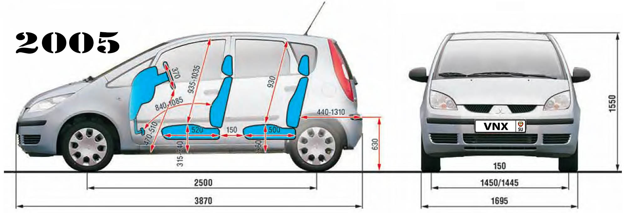
| № | Спецификация / Specs | Данные |
| Габариты (мм/mm) и масса (кг/kg) / Dimensions and Weight | ||
| 1 | Длина / Length | 3870 |
| 2 | Ширина (без/с зеркалами) / Width | 1695 |
| 3 | Высота (загружен/пустой) / Height | 1550 |
| 4 | Колёсная база / Wheelbase | 2500 |
| 5 | Дорожный просвет (клиренс) / Ground clearance | 150 |
| 6 | Снаряжённая масса / Total (curb) weight | 970 |
| Полная масса / Gross (max.) weight | 1450 | |
|
Двигатель / Engine |
||
| 7 | Тип / Engine Type, Code | Бензиновый, жидкостного охлаждения, четырехтактный, 3A90 |
| 8 | Количество цилиндров / Cylinder arrangement: Total number of cylinders, of valves | 3-цилиндровый, рядный, 12V, DOHC с верхним расположением двух распределительных валов |
| 9 | Диаметр цилиндра / Bore | 75.0 мм |
| 10 | Ход поршня / Stroke | 84.8 мм |
| 11 | Объём / Engine displacement | 1124 см³ |
| 12 | Система питания / Fuel supply, Aspiration | Распределенный впрыск топлива |
| Атмосферный | ||
| 13 | Степень сжатия / Compression ratio | 10.5:1 |
| 14 | Максимальная мощность / Max. output power kW (HP) at rpm | 55 кВт (75 л.с.) при 6000 об/мин |
| 15 | Максимальный крутящий момент / Max. torque N·m at rpm | 100 Нм при 3500 об/мин |
|
Трансмиссия / Transmission |
||
| 16 | Сцепление / Clutch type | 200×140 мм Однодисковое, сухое, с диафрагменной нажимной пружиной и гасителем крутильных колебаний, постоянно замкнутого типа |
| 17 | КПП / Transmission type | F5MGA МКПП 5 пятиступенчатая механическая, двухвальная, с синхронизаторами на всех передачах переднего хода |
О Книге
- Название: Mitsubishi Colt/ Colt CZ3/ Colt CZT Руководство по ремонту и эксплуатации
- Бензиновые двигатели: 3A90 1.1 л (1124 см³) 75 л.с./55 кВт, 4G19 1.3 л (1343 см³) 90 л.с./66 кВт, 4А90 1.3 л (1332 см³) 92-95 л.с./68-70 кВт, 4G15/4G15T 1.5 л (1468 см³) 98-110-150-154-166 л.с./72-81-110-113-122 кВт, 4А91 1.5 л (1499 см³) 105-106-109-111 л.с./77-78-80-81 кВт и дизельными OM639 1.5 л (1493 см³) 68-95 л.с./50-70 кВт
- Выпуск с 2002 года
- Серия: «Золотая»
- Год издания: 2010
- Автор: Коллектив авторов
- Издательство: «Ассоциация независимых издателей»
- Формат: PDF
- Страниц в книге: 292
- Размер: 50.99 МБ
- Язык: Русский
- Количество электросхем: 27

|
HOW TO USE THIS MANUAL. . . . . . |
00-2 |
|
TARGETS OF DEVELOPMENT . . . . |
00-2 |
|
PRODUCT FEATURES . . . . . . . . . . . |
00-2 |
|
TECHNICAL FEATURES. . . . . . . . . . |
00-3 |
|
EXTERIOR . . . . . . . . . . . . . . . . . . . . . . . . . |
00-3 |
|
INTERIOR . . . . . . . . . . . . . . . . . . . . . . . . . . |
00-4 |
|
SPACIOUS CABIN . . . . . . . . . . . . . . . . . . . |
00-4 |
|
ENGINE . . . . . . . . . . . . . . . . . . . . . . . . . . . |
00-5 |
|
TRANSMISSION. . . . . . . . . . . . . . . . . . . . . |
00-5 |
|
SUSPENSION. . . . . . . . . . . . . . . . . . . . . . . |
00-8 |
|
BRAKE . . . . . . . . . . . . . . . . . . . . . . . . . . . . |
00-10 |
|
STEERING . . . . . . . . . . . . . . . . . . . . . . . . . |
00-11 |
|
LOCAL INTERCONNECT NETWORK (LIN) |
00-12 |
|
. . . . . . . . . . . . . . . . . . . . . . . . . . . . . . . . . . . . . . |
|
|
ACTIVE SAFETY. . . . . . . . . . . . . . . . . . . . . |
00-13 |
|
PASSIVE SAFETY . . . . . . . . . . . . . . . . . . . |
00-17 |
|
EQUIPMENTS . . . . . . . . . . . . . . . . . . . . . . . |
00-20 |
|
ENVIRONMENTAL PROTECTION . . . . . . . |
00-21 |
|
SERVICEABILITY AND RELIABILITY . . . . |
00-21 |
|
VEHICLE IDENTIFICATION . . . . . . . . |
00-22 |
|
MAJOR SPECIFICATIONS . . . . . . . . |
00-23 |
|
00-2 |
GENERAL |
|
HOW TO USE THIS MANUAL |
HOW TO USE THIS MANUAL
MODEL INDICATIONS
The following abbreviations are used in this manual for identification of model types.
1100: Indicates models equipped with the 1,124 mL <134910> petrol engine.
1300: Indicates models equipped with the 1,332 mL <135930> petrol engine.
M2000029000242
1500: Indicates models equipped with the 1,499 mL <13590> petrol engine.
DOHC: Indicates an engine with the double overhead camshaft.
MIVEC: Indicates Mitsubishi innovative valve timing electronic control system.
MPI: Indicates the multipoint injection. M/T: Indicates the manual transmission. A/C: Indicates the air conditioner.
TARGETS OF DEVELOPMENT
M2000004000342
COLT has been developed as entry model of Mitsubishi model line-up, as compact passenger car with space MPV versatility.
PRODUCT FEATURES
ADVANCED AND FASHIONABLE STYLING
The one motion silhouette which consists of roominess and stylish appearance.
NEWLY DEVELOPED ENGINE WITH GOOD FUEL EFFICIENCY AND EXCELLENT POWER-DRIVEN PERFORMANCE
•134910-DOHC MIVEC* engine with 3-cylinder
•135930-DOHC MIVEC engine and
135950-DOHC MIVEC engine with 4-cylinder
NOTE: *MIVEC: Mitsubishi Innovative Valve timing Electronic Control system is a generic term for the engine with variable valve timing mechanism.
M2000005000174
HIGH LEVEL OF SAFETY
•Reinforced Impact Safety Evolution (RISE) chassis adopted
•Driver’s SRS airbag equipped as standard
•Front passenger’s SRS airbag, SRS side airbag, and SRS curtain airbag adopted <Optional>
•ISO FIX child seat fixing bar equipped as standard
EXCELLENT PRACTICABILITY AND SPACE UTILITY
•Multi function box storage as cup holder, ashtray, small item holder, etc.
•6:4 separate sliding, tumbling and removable rear seat.

|
GENERAL |
00-3 |
|
TECHNICAL FEATURES |
TECHNICAL FEATURES
EXTERIOR
M2000017000331
DESIGN FEATURES
1
2
5
 3
3
 4
4
OVERALL
•Dynamic one motion line connects chamfered front end.
•Simple body side section emphasis the wheel arches.
•Dynamic DLO (day light opening) creates car is motion even when car is stop.
•Front lights on the chamfered surface follows one of the Mitsubishi identity.
•Inside of the light reflectors given high-tech image of Japanese product.
•Simple exterior design emprises car’s functionality.
•Door cut’s matching the lines of the DLO and rear light.
1
6
AC311182AC
1. SIDE SILHOUETTE
Simple and dynamic one motion curve from the front nose to the roof end.
2. BODY SIDE SURFACE
Take simple and clean surface to emphasize wheel arches.
3. MITSUBISHI MARK
New Mitsubishi front face which designed every elements connects from three diamonds.
4. FRONT END CORNER
Apply the chamfer shape for easy handling.
5. HEAD LAMP
Create the high-tech image of Japanese product.
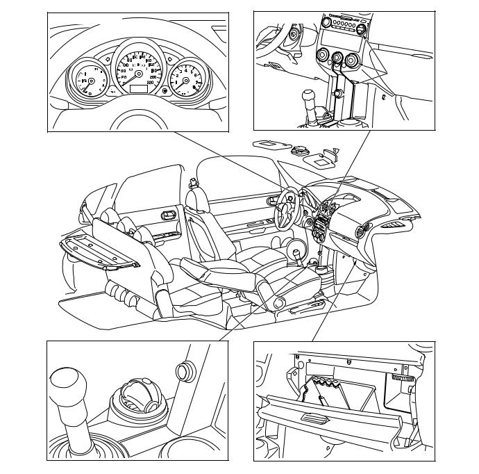
FLOOR CONSOLE AND DOOR TRIM
• Multi cup holder.
• Removable ashtray (This ashtray can be set in all cup holders).
COMBINATION METER
• Easy to recognize, independent function meters.
SPACIOUS CABIN
M2000000400025
|
00-4 |
GENERAL |
|
TECHNICAL FEATURES |
|
|
6. TAIL LAMP |
INTERIOR |
Apply long vertical type to easy to recognize from outside.
M2000018000312
DESIGN FEATURES
|
Combination meter |
Instrument panel |
|
Translucent |
|
|
parts |
|
|
AC312521AB |
|
|
Cup holder and ashtray |
Glove box |
OVERALL
• Sporty elegance feeling with comfortable space.
• The maximum roominess in the limited package.
INSTRUMENT PANEL
• Illumination systems presented by translucent parts of audio and A/C control panel
• Searchlight system from translucent parts.
• Useful glove box (card holder, pen holder, coin holders and bottle holder).
By the adoption of the long wheelbase, it realizes the interior length of the top-class.

|
GENERAL |
00-5 |
|
TECHNICAL FEATURES |
4 5
|
1 |
2 |
||||
|
3 |
|||||
|
AC311954AB |
|||||
|
No. |
Item |
Dimension mm |
No. |
Item |
Dimension mm |
|
1 |
Brake pedal room |
880 |
4 |
Front head room |
931 |
|
2 |
Hip point couple |
825 |
5 |
Rear head room |
862 |
|
3 |
Total leg room |
1,705 |
NOTE: Refer to P.00-23 for the body dimensions.
ENGINE
M2000020000223
The following three types of newly developed engines have been adopted to realize light weight, small size, and good fuel efficiency. Those engines are complied with Step 4 in European emissions regulations.
|
Item |
134910 |
135930 |
135950 |
||
|
Total displacement mL |
1,124 |
1,332 |
1,499 |
||
|
Bore × stroke mm |
75 × 84.8 |
75 × 75.4 |
75 × 84.8 |
||
|
Compression ratio |
10.5 |
||||
|
Combustion chamber |
Pentroof-type |
||||
|
Valve |
Intake opening |
BTDC 41° − ATDC 9° |
BTDC 41° − ATDC 9° |
BTDC 41° − ATDC 9° |
|
|
timing |
|||||
|
Intake closing |
ABDC 19° − ABDC 69° |
ABDC 3° − ABDC 53° |
ABDC 11° − ABDC 61° |
||
|
Exhaust opening |
BBDC 35° |
BBDC 35° |
BBDC 39° |
||
|
Exhaust closing |
ATDC 5° |
ATDC 5° |
ATDC 5° |
||
|
Maximum |
output kW(PS)/rpm |
55(75)/6,000 |
70(95)/6,000 |
80(109)/6,000 |
|
|
Maximum torque |
100(10.2)/3,500 |
125(12.7)/4,000 |
145(14.8)/4,000 |
||
|
N m(kg-m)/rpm |
|||||
TRANSMISSION
M2000021000226
The following two types of newly developed transmissions with light weight and small-size design have been adopted to realize good fuel efficiency.
•F5MGA 5-speed manual transmission
•F6SGA 6-speed automated manual transmission

|
00-6 |
GENERAL |
|
TECHNICAL FEATURES |
MANUAL TRANSMISSION
SECTIONAL VIEW
|
5th gear |
2nd gear |
Reverse gear |
1st gear |
Input shaft
Output shaft
4th gear
3rd gear
Differential
AC311790 AC

|
GENERAL |
00-7 |
|
TECHNICAL FEATURES |
AUTOMATED MANUAL TRANSMISSION
OUTSIDE VIEW
Shift actuator assembly
Drum position sensor
Clutch actuator 
AC311791AB
|
As automated manual transmission is designed |
SCHEMATIC DIAGRAM |
||
|
based on 6-speed manual gearbox and driven by |
|||
|
electric actuators (motors) via sophisticated |
|||
|
twin-drum shift mechanism, it gives our customers |
|||
|
«easy to drive as A/T», «fun to drive and high fuel effi- |
|||
|
ciency as M/T». |
|||
|
Shift actuator Automated manual transmission |
Clutch actuator |
||
|
assembly |
|||
Engine
Engine automated manual transmission electronic control unit (Engine-A-M/T-ECU)
|
Accelerator pedal |
N |
Allshift lever |
|
A |
||
|
Brake pedal |
DRIVING MODE
Driving mode provides either manual mode (like sequential M/T) or automatic mode (like conventional A/T), by tipping shift lever toward «A» or «+» or «−» from «s.b.» position.

|
00-8 |
GENERAL |
|
TECHNICAL FEATURES |
+: Up shifting
s.b.: Stand by (manual selection of gear) : Down shifting
A: Switch automatic manual mode
N: Neutral
R: Reverse gear
 : Automatic resume
 : Manual operation
|
AC312516AB |
|||
|
Position |
Operation |
Function |
Further explanation |
|
«N» |
In «N» |
Neutral |
Engine start possible only at «N». |
|
«R» |
«N» → «R» |
Reverse drive |
No creeping. |
|
s.b. (stand |
«N» → s.b. |
Forward drive |
Creeping starts (with brake pedal depress). |
|
by) |
|||
|
Auto mode or Manual |
Starts from auto mode. <135950> |
||
|
mode |
|||
|
Starts from manual mode. <135930> |
|||
|
«A» |
s.b. → «A» |
Mode change |
Auto mode or Manual mode comes alternatively. |
|
(tip) |
(Auto mode → Manual mode → Auto mode → Manual |
||
|
mode) |
|||
|
«+», «−» |
s.b. → «+» |
+: Manual up shifting |
Higher gear will be selected. *1, *2 |
|
(tip) |
|||
|
−: Manual down shifting |
Lower gear will be selected. *1, *3 |
||
|
s.b. → «−» |
|||
|
*1: After «+» or «−» tip action, mode becomes manual mode. |
|||
|
(tip) |
|||
|
*2: If vehicle speed is too low, some up shifts neglected. |
|||
|
*3: If engine speed is too high, down shifting neglected. |
|||
SUSPENSION
M2000023000211
FRONT SUSPENSION
The newly developed MacPherson Strut suspension with compatible characteristics of high rigidity and light weight has been adopted for the front suspension to realize sufficient driving comfort and driving stability.

|
GENERAL |
00-9 |
|
TECHNICAL FEATURES |
Strut assembly
Coil spring
Stabilizer bar
Lower arm
Crossmember
AC310151AB
REAR SUSPENSION
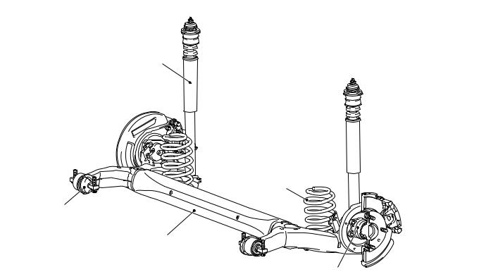
The torsion beam suspension has been adopted for the rear suspension to realize a large suspension stroke and excellent driving comfort. The suspension with small-size design has provided ample interior space.
|
00-10 |
GENERAL |
|
TECHNICAL FEATURES |
Shock absorber
Coil spring
Arm bushing
Torsion beam and arm assembly
|
Unit type bearing |
AC310152AB |
BRAKE
M2000024000043
14-inch ventilated disk brake for the front, 8-inch leading trailing drum brake or 14-inch solid disk brake for the rear have been installed to realize high reliability and durability along with excellent braking performance.

|
GENERAL |
00-11 |
|
TECHNICAL FEATURES |
<Vehicle with rear drum brake>
Brake booster
Hydraulic unit
(Integrated with ABS-ECU/Active Stability Control System-ECU)
Rear drum brake
Master cylinder
Parking brake lever
|
Front disc brake |
AC311564 |
<Vehicle with rear disc brake>
Brake booster
Hydraulic unit
(Integrated with ABS-ECU/Active Stability Control System-ECU)
|
Master cylinder |
Rear disc brake |
|
|
Parking brake lever |
||
|
Front disc brake |
AC311651 |
|
|
AC311650AB |
STEERING
M2000040000010
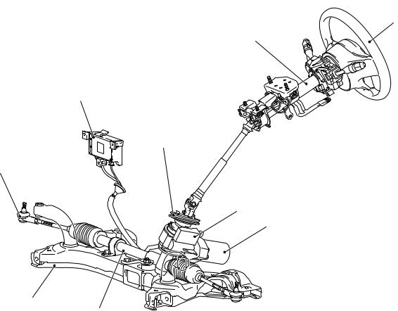
Due to the adoption of electric power steering driven by newly developed pinion shaft, effortless steering wheel manoeuvring at the low speed as well as stable steering wheel manoeuvring at the mid to high speed has been achieved.
|
00-12 |
GENERAL |
|
TECHNICAL FEATURES |
Steering wheel
Steering column assembly
Electric power steering-ECU
Dash panel cover
Tie rod end
Torque sensor
Motor
Crossmember
LOCAL INTERCONNECT NETWORK (LIN)
M2000041000013
LIN refers to «Local Interconnect Network», a global
standard of serial multiplex communication protocol*1 administrated by LIN consortium. A communication circuit employing the LIN protocol connects each ECU, and switch data can be shared among ECUs, which enables more reduction in wiring. Transmission speed is 19.2 kbps.
For COLT, ETACS*2-ECU can receive some input
NOTE: *1: The regulations have been decided in detail, from software matters such as the necessary transmission rate for communication, the system, data format, and communication timing control method to hardware matters such as the harness type and length and the resistance values.
NOTE: *2: ETACS (Electronic Time and Alarm Control System)
NOTE: *3: CAN (Controller Area Network)
signals through CAN*3 communication in addition to the LIN communication.

|
GENERAL |
00-13 |
|
TECHNICAL FEATURES |
ACTIVE SAFETY
M2000031000216
BRAKING SYSTEM
ABS warning lamp
Brake warning lamp
AC311642
Hydraulic unit and
ABS-ECU
Diagnosis connector
|
Stop lamp switch |
Wheel speed sensor |
|
Wheel speed sensor |
AC311643 |
|
AC311644AC |
|
00-14 |
GENERAL |
|
TECHNICAL FEATURES |
|
Engine-ECU <M/T> or Engine-A-M/T-ECU* |
|||
|
Front-left wheel speed sensor |
<Automated manual transmission> |
||
|
Front right solenoid valve (out) |
|||
|
Rear-left wheel speed sensor |
Front right solenoid valve (in) |
||
|
Rear-right wheel speed sensor |
Front left solenoid valve (out) |
||
|
Front-right wheel speed sensor |
Front left solenoid valve (in) |
||
|
Stop lamp switch |
Rear right solenoid valve (out) |
||
|
ABS-ECU |
Rear right solenoid valve (in) |
||
|
ABS-ECU power supply |
Rear left solenoid valve (out) |
||
|
Rear left solenoid valve (in) |
|||
|
Brake warning lamp |
|||
|
ABS warning lamp |
|||
|
Diagnosis connector |
|||
|
Stop lamp switch |
|
Front-right wheel (FR) |
Rear-right wheel (RR) |
|
Front-right |
Rear-right wheel |
|
|
wheel |
speed sensor |
|
|
speed |
||
|
sensor |
Note |
|
|
*Engine-A-M/T-ECU: |
||
|
Hydraulic |
Engine automated manual |
|
|
transmission electronic |
||
|
unit (HU) |
||
|
control unit |
||
|
: CAN-bus line |
|
Front-left wheel |
Rear-left wheel |
|
speed sensor |
speed sensor |
|
Front-left wheel (FL) |
Rear-left wheel (RL) |
AC311645AC
4-WHEEL ANTI-SKID BRAKING SYSTEM (4ABS)
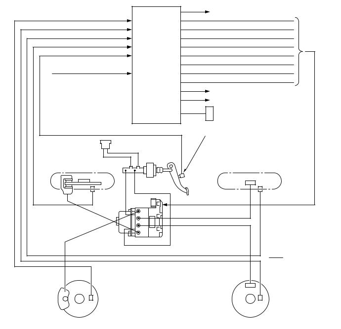
A 4-wheel anti-skid braking system (4ABS) has been adopted to prevent slipping caused by the vehicle wheels locking up, in order to minimize braking distance, and also to maintain a stable vehicle posture and steering performance.
ELECTRONIC BRAKE-FORCE DISTRIBUTION (EBD)
An electronic brake-force distribution (EBD) which makes it possible to maintain the maximum amount of braking force even when the vehicle’s load is varied has been adopted.

|
GENERAL |
00-15 |
|
TECHNICAL FEATURES |
ANTI-SKID BRAKE SYSTEM (ABS)/ACTIVE STABILITY CONTROL SYSTEM
Anti-skid Brake/Active stability control indicator lamp
Steering wheel sensor
Pressure sensor, Hydraulic unit and Anti-skid Brake/Active stability control system control unit (ABS/Active stability control system-ECU)
Diagnosis connector
Engine-ECU <M/T> or Engine-A-M/T-ECU (Engine automated manual transmission electronic control unit)
<Automated manual transmission>
G and yaw rate sensor
Wheel speed sensor
Stop lamp switch
|
Wheel speed sensor |
AC311649AC |

|
00-16 |
GENERAL |
|
TECHNICAL FEATURES |
Front-left wheel speed sensor
Rear-left wheel speed sensor
Rear-right wheel speed sensor
Front-right wheel speed sensor
Master cylinder pressure sensor
Stop lamp switch
Power supply to ABS/Active stability control system-ECU
Steering wheel sensor
G and yaw rate sensor
Engine-ECU <M/T> or engine-A- M/T-ECU <Automated manual transmission>
ABS/Active stability control system-ECU
Combination meter ABS/Active stability control indicator lamp
Diagnosis
Connector
Suction valve (FR)
Suction valve (FL)
Cut valve (FR)
Cut valve (FL)
Control solenoid valve (FR) IN
Control solenoid valve (FR) OUT
Control solenoid valve (FL) IN
Control solenoid valve (FL) OUT
Control solenoid valve (RR) IN
Control solenoid valve (RR) OUT
Control solenoid valve (RL) IN
Control solenoid valve (RL) OUT
Pamp motor
G and yaw rate sensor
|
Front-right wheel (FR) |
Rear-right wheel (RR) |
||
|
Steering |
||
|
Wheel |
wheel |
Wheel |
|
sensor |
||
|
speed |
speed |
|
|
sensor |
sensor |
|
|
Stop lamp |
||
|
switch |
||
|
Engine-ECU <M/T> or engine- |
||
|
A-M/T-ECU <Automated manual |
||
|
transmission> |
||
|
Hydraulic |
||
|
unit |
Wheel speed |
|
|
Wheel speed |
||
|
sensor |
sensor |
Front-left wheel (FL)
Rear-left wheel (RL)
Note
|
: CAN-bus line |
AC311782AC |

|
GENERAL |
00-17 |
|
TECHNICAL FEATURES |
The Anti-skid Brake System (ABS)/Active stability control system is a combination system of active stability control system and anti-skid brake control system. The active stability control system avoids a dangerous vehicle attitude by limiting the engine output and braking a set of wheels (left front and right rear, or right front and left rear) according to driving conditions. The anti-skid brake control system prevents wheel spinning at vehicle start.
ABS/Active stability control system is available for all models as optional equipment.
PASSENGER’S AIR BAG CUT OFF SWITCH
AC311721
AC311720
AC312760 AB
Passenger’s air bag cut off switch is located in the glove box.
The passenger’s air bag cut off switch can be used to disable the passenger’s (front) air bag.
PASSIVE SAFETY
M2000032000208
IMPACT SAFETY BODY
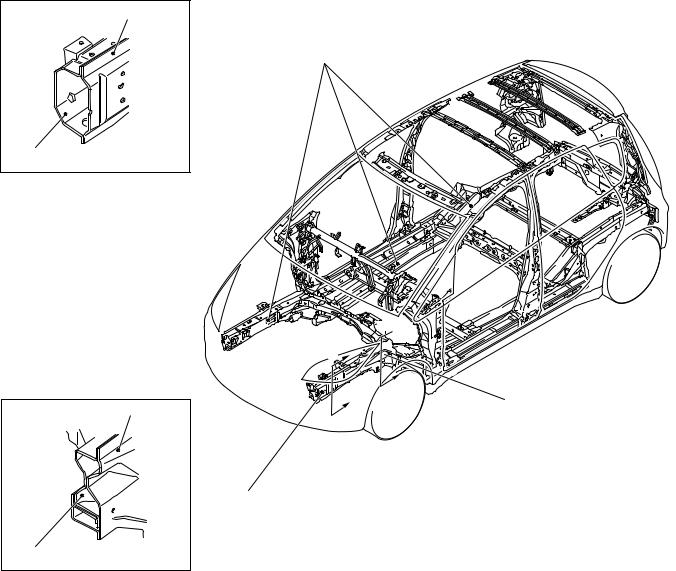
The front and rear structures to absorb high energy, and the highly tough cabin structure reduce the risk of passenger injuries at front-, rear-, and side-impact collisions, secure the space for life protection, and facilitate rescuing passengers.
|
00-18 |
GENERAL |
|
TECHNICAL FEATURES |
Section A — A Front side member outer
Front side member
Section B — B Front side member outer
1
|
Front side member |
||
|
inner |
AB301791 |
AB301835AB |
1.The octagonal cross section for the front of the front sidemember and 8-shaped cross section for the rear of the front sidemember have been adopted for enlargement so that the applied structures can effectively absorb energy from the impact at the time of collision.
2.Due to the adoption of straightened front sidemember and the rear floor sidemember, the structure can effectively absorb energy from the impact at the time of collision.

|
GENERAL |
00-19 |
|
TECHNICAL FEATURES |
SUPPLEMENTAL RESTRAINT SYSTEM (SRS) AND FRONT SEAT BELTS WITH PRE-TENSIONER
|
Driver’s air bag |
Curtain air bag modules |
|
|
module |
Passenger’s (front) |
|
|
Seat belt with |
||
|
air bag module |
||
|
pre-tensioner |
Side air bag modules
SUPPLEMENTAL RESTRAINT SYSTEM (SRS)
The SRS is designed to supplement the front seat belts. It eliminates or reduces injury to the front passenger(s) by deploying air bag(s) in case of a head-on collision.
AC313299AB
SEAT BELT WITH PRE-TENSIONER
The seat belts with pre-tensioner work simultaneously with the SRS. The pre-tensioner takes up seat belt slack immediately when a collision takes place, restraining the front passengers sooner than the SRS. This prevents the passengers from moving forward.
SRS SIDE AIR BAG
Side air bag systems in the front seats are activated when sideward impacts applied to the vehicle exceed a threshold to protect the occupants’ upper bodies.
SRS CURTAIN AIR BAG
The curtain air bag systems are activated when sideward impacts applied to the vehicle exceed a threshold, to protect the heads of the occupants in the front and rear seats.
STEERING SHAFT AND STEERING COLUMN
The impact absorption mechanism in combination of retractable steering shaft and steering column disengagement mechanism has been adopted to alleviate the impact from the steering wheel to the driver.
BRAKE PEDAL
The brake pedal backward movement restraint mechanism to restrain the backward movement of the brake pedal to the minimum at the time of frontal collision has been adopted so that the impact to the lower limbs of the driver can be alleviated.
|
00-20 |
GENERAL |
|
TECHNICAL FEATURES |
CHILD SEAT FIXING BAR COMPATIBLE WITH ISO FIX*
The anchor bar has been equipped as standard for easily and securely fixing the child seat compatible with ISO FIX.
NOTE: *ISO: International Organisation for Standardisation
REAR SEAT BELT WITH CHILD SEAT FIXING MECHANISM (ALR*)
The child seat fixing mechanism has been adopted to easily and securely fix the child seat that is not compatible with ISO FIX.
NOTE: *ALR: Automatic Locking Retractor
POWER WINDOW WITH SAFETY MECHANISM
The power window with safety mechanism has been adopted to automatically roll down and stop the door window glass as soon as the occurrence of jamming is detected at the time of rolling up the door window glass.
Multi-centre display
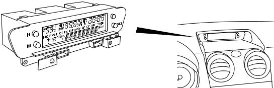
The multi-centre display to provide vehicle information in the text form has been equipped on the centre console as standard. The multi-centre display has the following functions:
• Clock
SUNROOF WITH SAFETY MECHANISM
The sunroof with safety mechanism has been adopted so that the roof lid glass can move in the reverse direction and stop when application of external force hinders the movement during the sliding to close or tilt down operation.
TRIMS AND HEADLINING
The head impact absorption structure has been adopted for the pillar trim, quarter trim, and headlining so that impact towards the head of a passenger can be reduced.
OTHER SAFETY FEATURES
•3-point ELR seat belts
•Child-protection rear door locks
•Front fog lamps <Optional>
•Rear fog lamp (Driver’s side)
EQUIPMENTS
M2000026000191
MULTI-CENTRE DISPLAY
AC311613 AB
•Outside temperature
•Vehicle information (average speed, instant fuel consumption, remaining distance)
•Audio information
|
GENERAL |
00-21 |
||
|
TECHNICAL FEATURES |
|||
|
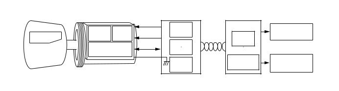
IMMOBILIZER SYSTEM |
|||
|
Ignition key |
Key ring antenna |
ETACS-ECU |
Engine-ECU <M/T> or Engine-A-M/T-ECU* |
|
(immobilizer-ECU) |
<Automated manual transmission> |
|
Power |
|||
|
Encrypted |
AMP |
SCI |
Clock |
|
code |
Data |
||
|
RF circuit |
|||
|
Transponder |
|||
|
Steering lock |
|
SCI |
CAN- |
CPU |
Ignition |
|
CPU |
Bus |
||
|
CAN- |
CAN-I/F |
Injection |
|
|
I/F |
|
Note |
|
|
*Engine-A-M/T-ECU: Engine automated manual transmission electronic control unit |
AC312166AC |
All models are equipped with the immobilizer system as standard. The immobilizer system is the theft prevention system designed for prohibiting the engine from fuel injection so that the vehicle cannot be started if someone tries to start the engine with something other than the ignition key encrypted for that vehicle.
ENVIRONMENTAL PROTECTION
M2000027000257
Mitsubishi has given careful consideration to protection of natural resources and the environment in the vehicle. Environmentally friendly features are shown below.
IMPROVEMENT ON RECYCLING EFFICIENCY
|
Category |
Part name |
Feature |
|
Recyclable materials |
Door handle |
Thermo plastics-easy recyclable |
|
Bumper |
||
|
Radiator grille |
||
|
Instrument panel |
||
|
Recycled materials |
Engine oil level gauge |
Recycled from other industries |
|
scrap |
||
|
REDUCTION OF MATERIAL BURDEN ON ENVIRONMENTt |
||
|
Category |
Part name |
Feature |
|
Elimination of hazardous |
Radiator core and heater core |
Lead free materials |
|
substances |
||
|
Windshield ceramic print |
||
|
Body electrodeposited coating |
||
|
Battery cable connector |
||
|
Wiring harness |
||
|
Water proof film |
Polyvinyl chloride (PVC) free |
|
|
material |
||
|
Prevention of ozone depletion |
Air conditioner refrigerant |
HFC134a refrigerant |
SERVICEABILITY AND RELIABILITY
M2000028000272
MUT-III (MULTI USE TESTER-III)
Comprehensive improvements have been made to the MUT-II, a tester for diagnosing problems with the electronic control system. For easier servicing, the newly developed MUT-III has greatly improved functions and is much easier to use. The MUT-III expands the functions of the MUT-II in the following
ways:
1.Interactive Error Diagnosis
•In response to the nature of the problem, the corresponding troubleshooting page from the maintenance manual is retrieved.
•Service data is displayed, and from the actuator test screen, the page of the maintenance manual is retrieved for a list of inspection reference values.
|
00-22 |
GENERAL |
|
VEHICLE IDENTIFICATION |
2.Service Manual Viewer
•The technical information manual and workshop manual can be displayed on a personal computer monitor.
3.CAN* bus diagnosis
•Auto diagnosis function for the CAN communications bus line.
NOTE: *CAN: Controller Area Network (for further details, refer to GROUP 54C P.54C-2).
IMPROVED SERVICEABILITY
•Since adoption of unvolatile memory (EEPROM*) helps the learned value not to be initialised when the battery terminal or connector of the control unit is disconnected, maintainability can be improved.
NOTE: *EEPROM: Electrical Erasable Programmable ROM (information to be memorised can be electronically written into and erased from ROM)
•Since the adoption of service hole at the quarter trim is designed for removal and installation of the rear shock absorber assembly, maintainability can be improved.
•Since the adoption of electric power steering makes hydraulic pipes and oil pumps unnecessary, maintainability can be improved.
•Since adoption of service hole at the splash shield helps for removal and installation of headlamp bulb (low beam) and front turn signal lamp bulb, maintainability can be improved.
•The instrument lower panel can be removed or installed without using tools at the time of fuse replacement in the junction block.
VEHICLE IDENTIFICATION
|
MODELS |
M2000001000644 |
||||||||||||||||||||||||||||||||||||
|
Model code |
Engine model |
Transmission model |
Fuel supply |
||||||||||||||||||||||||||||||||||
|
system |
|||||||||||||||||||||||||||||||||||||
|
Z32A |
XNLHL6 |
134910-DOHC MIVEC (1,124 mL) |
F5MGA <2WD, 5M/T> |
MPI |
|||||||||||||||||||||||||||||||||
|
XNLHR6 |
|||||||||||||||||||||||||||||||||||||
|
Z34A |
XNLHL6 |
135930-DOHC MIVEC (1,332 mL) |
|||||||||||||||||||||||||||||||||||
|
XNLHR6 |
|||||||||||||||||||||||||||||||||||||
|
XJLHL6 |
F6SGA <2WD, 6-speed |
||||||||||||||||||||||||||||||||||||
|
automated manual |
|||||||||||||||||||||||||||||||||||||
|
XJLHR6 |
|||||||||||||||||||||||||||||||||||||
|
transmission> |
|||||||||||||||||||||||||||||||||||||
|
Z36A |
XNLHL6 |
135950-DOHC MIVEC (1,499 mL) |
F5MGA <2WD, 5M/T> |
||||||||||||||||||||||||||||||||||
|
XNLHR6 |
|||||||||||||||||||||||||||||||||||||
|
XJLHL6 |
F6SGA <2WD, 6-speed |
||||||||||||||||||||||||||||||||||||
|
automated manual |
|||||||||||||||||||||||||||||||||||||
|
XJLHR6 |
|||||||||||||||||||||||||||||||||||||
|
transmission> |
|||||||||||||||||||||||||||||||||||||
|
MODEL CODE |
|||||||||||||||||||||||||||||||||||||
|
No. |
Item |
Content |
|||||||||||||||||||||||||||||||||||
|
1 |
Development |
Z3 |
MITSUBISHI COLT |
||||||||||||||||||||||||||||||||||
|
2 |
Engine type |
2 |
1,124 mL petrol engine |
||||||||||||||||||||||||||||||||||
|
Z3 |
2 |
A |
X |
N |
L |
H |
L |
6 |
4 |
1,332 mL petrol engine |
|||||||||||||||||||||||||||
|
6 |
1,499 mL petrol engine |
||||||||||||||||||||||||||||||||||||
|
3 |
Sort |
A |
Passenger car |
||||||||||||||||||||||||||||||||||
|
1 |
2 |
3 |
4 |
5 |
6 |
7 |
8 |
9 |
|||||||||||||||||||||||||||||
|
4 |
Body style |
X |
4-door hatchback |
||||||||||||||||||||||||||||||||||
|
AC311514 |
|||||||||||||||||||||||||||||||||||||

|
GENERAL |
00-23 |
|
MAJOR SPECIFICATIONS |
|
No. |
Item |
Content |
|
|
5 |
Transmission |
N |
5-speed manual |
|
type |
transmission |
||
|
J |
6-speed automated |
||
|
manual transmission |
|||
|
6 |
Trim level |
L |
L-line |
|
7 |
Specification |
H |
MPI-DOHC MIVEC |
|
engine feature |
|||
|
8 |
Steering wheel |
L |
Left hand drive |
|
location |
|||
|
R |
Right hand drive |
||
|
9 |
Destination |
6 |
For Europe |
MAJOR SPECIFICATIONS
|
M2000030000268 |
||||
|
8 |
||||
|
1 |
7 |
4 |
5 |
9 |
|
3 |
||||
|
2 |
6 |
|||
|
AC313517AB |
|
Item |
Z32A |
Z34A |
Z36A |
||||
|
XNLHL6/R6 |
XNLHL6/R6 |
XJLHL6/R6 |
XNLHL6/R6 |
XJLHL6/R6 |
|||
|
Vehicle |
Front track |
1 |
1,460 |
||||
|
dimensions |
|||||||
|
Overall width |
2 |
1,695 |
|||||
|
mm |
|||||||
|
Front overhang |
3 |
780 |
|||||
|
Wheel base |
4 |
2,500 |
|||||
|
Rear overhang |
5 |
590 |
|||||
|
Overall length |
6 |
3,870 |
|||||
|
Ground clearance |
7 |
154/169* |
|||||
|
Overall height |
8 |
1,550/1,565* |
|||||
|
Rear track |
9 |
1,445 |
|||||
|
00-24 |
GENERAL |
||||||||
|
MAJOR SPECIFICATIONS |
|||||||||
|
Item |
Z32A |
Z34A |
Z36A |
||||||
|
XNLHL6/R6 |
XNLHL6/R6 |
XJLHL6/R6 |
XNLHL6/R6 |
XJLHL6/R6 |
|||||
|
Vehicle |
Kerb weight |
965 |
970 |
975 |
990 |
995 |
|||
|
weight kg |
|||||||||
|
Max. gross vehicle |
1,450 |
1,460 |
1,465 |
||||||
|
weight |
|||||||||
|
Max. axle weight |
735 |
745 |
750 |
||||||
|
rating-front |
|||||||||
|
Max. axle weight |
745 |
||||||||
|
rating-rear |
|||||||||
|
Max. |
With brake |
1,000 |
|||||||
|
trailer |
|||||||||
|
Without |
500 |
||||||||
|
weight |
|||||||||
|
brake |
|||||||||
|
Max. trailer |
-nose |
50 |
|||||||
|
weight |
|||||||||
|
Seating capacity |
5 |
||||||||
|
Engine |
Model code |
134910 |
135930 |
135950 |
|||||
|
Total displacement mL |
1,124 |
1,332 |
1,499 |
||||||
|
Transmission |
Model code |
F5MGA |
F6SGA |
F5MGA |
F6SGA |
||||
|
Type |
5-speed manual |
6-speed |
5-speed |
6-speed |
|||||
|
transmission |
automated |
manual |
automated |
||||||
|
manual |
transmission |
manual |
|||||||
|
transmission |
transmission |
||||||||
|
Fuel system |
Fuel supply system |
MPI |
|||||||
NOTE: *: Vehicles with high ground suspension

11-1
GROUP 11
CONTENTS
ENGINE MECHANICAL <134>. . . . . . . . . . . . . . . . . . . . . . . . . . 11A ENGINE MECHANICAL <135>. . . . . . . . . . . . . . . . . . . . . . . . . . 11B

11A-1
GROUP 11A
ENGINE
MECHANICAL <134>
CONTENTS
|
GENERAL INFORMATION . . . . . . . . |
11A-2 BASE ENGINE . . . . . . . . . . . . . . . . . . |
11A-3 |

11A-2 ENGINE MECHANICAL <134>
GENERAL INFORMATION
GENERAL INFORMATION
The newly developed 1.1L 134910 engine features 3-cylinder, 12-valve, and double overhead camshafts (DOHC).
The engine family has the following features.
•Aluminum cylinder block
•A counter balance shaft
M2112000100404
•MIVEC (Mitsubishi Innovative Valve timing Electronic Control system)
•Selective valve tappet of direct acting valve system for valve clearance adjustment
•Timing chain
MAJOR SPECIFICATIONS
|
Item |
Specification |
|
|
Total displacement mL |
1,124 |
|
|
Bore × Stroke mm |
75 × 84.8 |
|
|
Compression ratio |
10.5 |
|
|
Compression chamber |
Pentroof-type |
|
|
Valve timing |
Intake opening |
BTDC 41° − ATDC 9° |
|
Intake closing |
ABDC 19° − ABDC 69° |
|
|
Exhaust opening |
BBDC 35° |
|
|
Exhaust closing |
ATDC 5° |
|
|
Maximum output kW (PS)/rpm |
55 (75)/6,000 |
|
|
Maximum torque Nm (kgm)rpm |
100 (10.2)/3,500 |
|
|
Fuel system |
Electronically controlled multipoint fuel injection |
|
|
Ignition system |
Electronic-controlled 3-coil |
|
|
ENGINE MECHANICAL <134> |
11A-3 |
|
BASE ENGINE |
BASE ENGINE
M2112001000325
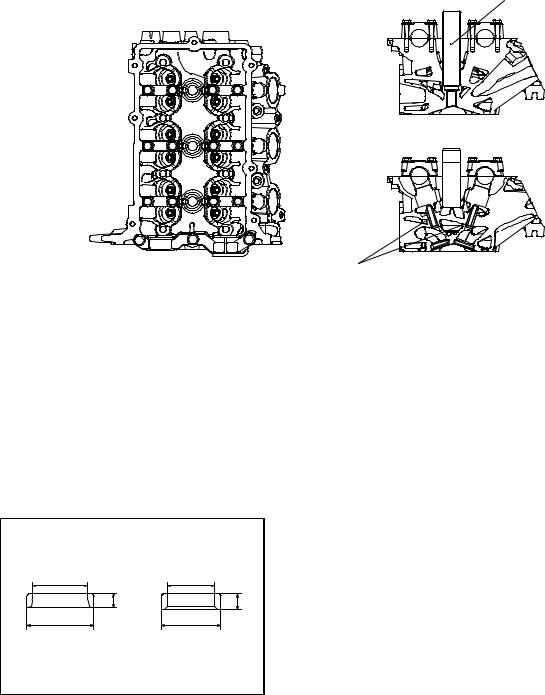
CYLINDER HEAD
Spark plug guide
Valve guide
AK305051AB
The cylinder head is made of aluminum alloy, which is lightweight and has an excellent cooling efficiency. The pentroof type combustion chamber has a spark plug in the center. The valve angle is relatively small, contributing to size reduction.
The intake and exhaust ports are arranged in a cross-flow construction. Each cylinder has a pair of intake ports on one side and a pair of exhaust ports on the other side.
Each of the intake and exhaust camshafts is supported by 4 bearings. On each camshaft, the thrust load is supported by No. 1 bearing. The No. 1 bearings for the intake and exhaust camshafts have a common bearing cap.
VALVE SEAT
|
Intake |
Exhaust |
|
d |
d |
|
h |
h |
|
D |
D |
Sintered alloy valve seat
|
Item |
Intake |
Exhaust |
|
D (Outer diameter) mm |
31.5 |
28 |
|
d (Inner diameter) mm |
26 |
22 |
|
h (height) mm |
6.6 |
7.3 |
AK305052AB
|
11A-4 |
ENGINE MECHANICAL <134> |
|
BASE ENGINE |
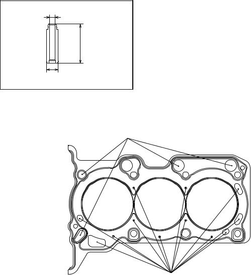
VALVE GUIDE
The intake and exhaust valves use the same-design valve guide.
|
Item |
Specification |
|
D (Outer diameter) mm |
10.5 |
|
d (Inner diameter) mm |
4.5 |
|
h (height) mm |
34.5 |
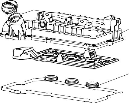
CYLINDER HEAD GASKET
Oil hole
Water hole
AK305055AB
The metal gasket having the one layer of wave stopper is used for the cylinder head gasket.
|
ENGINE MECHANICAL <134> |
11A-5 |
|
BASE ENGINE |
CYLINDER HEAD COVER
Cylinder head cover
 Plate
Plate
Oil seal
Cylinder head
 cover gasket
AK305057AB
A resin cylinder head cover is used for the cylinder head.
The oil plate and the oil seal are integrated with the cylinder head cover assembly.

|
11A-6 |
ENGINE MECHANICAL <134> |
|
BASE ENGINE |
|
|
CYLINDER BLOCK |
|
|
Right side view |
Front view |
Front
Nipple
|
Left side view |
Rear view |
|
Front |
|
Thermostat case installation position |
Oil filter installation position |
AK305060 AB |
The cylinder block is made of lightweight aluminum alloy.
The crankshaft journal is supported by 4 bearings. The crankshaft thrust load is supported by No. 3 bearing.
The water jacket is of a full-siamese design.
A nipple is provided at the front of the block to supply engine oil onto the timing chain.
|
Item |
Dimen |
|
sion |
|
|
Overall height mm |
280 |
|
Overall length mm |
292.1 |
|
Top face to crankshaft center mm |
205 |
|
Crankshaft center to bottom face mm |
75 |
|
Bore mm |
75 |
|
Bore pitch mm |
83 |
|
Stroke mm |
84.8 |

|
ENGINE MECHANICAL <134> |
11A-7 |
|
BASE ENGINE |
REAR OIL SEAL CASE
The rear oil seal case is a sheet-metal work. The case is installed with sealant applied onto the mounting face to prevent oil leakage.
A
AK305061AB
PISTON
 Front mark
 Piston pin offset
AK305063AC
PISTON PIN
d D
h
AK305064AB
The piston is made of special aluminum alloy. Weight reduction is achieved by minimizing the overall height while maximizing the recess on both ends of the piston pin.
The center of the piston pin hole is offset by 0.5 mm from the center of the piston towards the thrust side. The piston skirt has a streak finish to enhance oil retention and anti-seizing property.
|
Item |
Dimension |
|
Base diameter mm |
75 |
|
Pin diameter mm |
18 |
|
Overall height mm |
46.04 |
The piston pin is of a semi-floating type, press-fitted into the connecting rod small end while capable of floating relative to the piston.
|
Item |
Dimension |
|
Outer diameter mm |
18 |
|
Inner diameter mm |
11 |
|
Overall length mm |
50 |

|
11A-8 |
ENGINE MECHANICAL <134> |
|
|
BASE ENGINE |
||
|
PISTON RING |
||
|
Piston ring No.1 |
Piston ring No.2 |
Piston ring No.1
Maker mark
Piston ring No.2
Oil ring
Oil ring
AK305365AB
Each piston is provided with No. 1 and No. 2 compression rings and an oil ring.
|
Item |
No. 1 piston ring |
No. 2 piston ring |
Oil ring |
|
Shape |
Barrel |
Tapered |
3-piece |
|
Surface treatment (Contact |
Nitride coated |
Parkerized |
Hard chrome plated |
|
face with cylinder) |
|||
|
Maker mark |
R |
2R |
No marking |

|
ENGINE MECHANICAL <134> |
11A-9 |
|
BASE ENGINE |
CONNECTING ROD
The connecting rod is made of highly rigid, forged carbon steel. The rod portion has an H-shaped cross section.
The connecting rod big end bearing is lubricated through an oil passage running from the main journal to the crankshaft pin.
|
Item |
Dimension |
|
d (Small end inner |
18 |
|
diameter) mm |
|
|
D (Large end inner |
43 |
|
diameter) mm |
|
|
L (Center distance) mm |
135.6 |
CONNECTING ROD BEARING
 A
A
Identification color
H
AK305309AB
The upper and lower connecting rod bearing halves are identical.
The connecting rod bearing is equipped with back metal. While the bearing itself is made of aluminum alloy, the back metal is normally made of steel sheet. The connecting rod bearing is narrower than the bearing cap, this is to minimize wear.
|
Item |
Dimension |
|
H (Width) mm |
13.5 |
|
A (Thickness) mm |
1.5 |

|
11A-10 |
ENGINE MECHANICAL <134> |
|
BASE ENGINE |
CRANKSHAFT
Crankshaft sensing ring
Balance weight
Oil pump drive gear shaft
|
Crankshaft |
||
|
sprocket |
Oil hole |
|
|
Crankshaft |
Balance weight |
Crankshaft |
|
sprocket B |
||
AK305069AB
A casted crankshaft is used for the crankshaft. The crankshaft consists of 4 main bearings and 4 balance weights.
The crankshaft pins are arranged at 120° intervals. The oil hole supplies lubrication oil from the journal to the crank pin.
A crankshaft sprocket, an oil pump drive gear shaft, and crankshaft sprocket B are press-fitted onto the front of the crankshaft.
The crankshaft is also fitted with a crankshaft sensing ring.
CRANKSHAFT BEARING, THRUST BEARING
|
Front |
|
|
Upper bearing |
|
|
Thrust bearing |
Oil groove |
|
Oil hole |
|
|
Groove |
Identification |
|
color |
|
|
Lower bearing |
|
|
Identification |
|
|
color |
AK305071AB
The upper crankshaft bearing (with oil groove) is located on the cylinder block side while the lower bearing (without oil groove) is held by the bearing cap.
The crankshaft bearing is equipped with back metal. While the bearing itself is made of aluminum alloy, the back metal is made of steel sheet.
A thrust bearing is installed on both sides of the No. 3 crankshaft bearing.

|
ENGINE MECHANICAL <134> |
11A-11 |
|||
|
BASE ENGINE |
||||
|
Item |
Dimensio |
|||
|
n |
||||
|
Crankshaft bearing |
Width mm |
16 |
||
|
Thickness |
20 |
|||
|
mm |
||||
|
Crankshaft thrust bearing |
Thickness |
3.275 |
||
|
mm |
||||
CRANKSHAFT PULLEY
Timing mark
The crankshaft pulley is made of steel plate. The pulley has grooves to engage with a V-ribbed belt (5 ribs), which drives an alternator and a water pump.
AK305073AC
An ignition timing mark (notch) is stamped on the flange of the pulley.

|
11A-12 |
ENGINE MECHANICAL <134> |
|
BASE ENGINE |
FLYWHEEL
Flywheel
Ring gear
AK305074AB
The flywheel is made of cast-iron. A separate ring gear is mounted on it.

|
ENGINE MECHANICAL <134> |
11A-13 |
|
|
BASE ENGINE |
||
|
TIMING CHAIN TRAIN |
||
|
Timing chain mark |
Timing mark |
Timing chain mark |
|
link plate (bule) |
||
|
link plate (bule) |
||
|
Camshaft sprocket |
V.V.T. sprocket |
|
|
timing mark |
timing mark |
|
|
Camshaft sprocket |
V.V.T. sprocket |
|
|
Tensioner lever |
||
|
Chain guide |
||
|
Timing chain |
||
|
tensioner |
||
|
Timing mark |
Timing chain mark |
|
|
Crankshaft |
link plate (bule) |
|
|
sprocket |
||
|
timing mark |
||
|
Crankshaft sprocket |
||
|
AK305058AB |
The 2 camshafts are driven by the timing chain via the respective sprockets.
The timing chain, consisting of 122 links, is an endless chain, connecting the crankshaft sprocket with the camshaft and V.V.T. sprockets.
The timing chain is equipped with 3 mark link plates (blue) to correctly time the 3 sprockets with each other.
The timing chain is tensioned by the timing chain tensioner, which has a built-in plunger with plunger springs.
|
Item |
No. of |
|
teeth |
|
|
Camshaft sprocket |
36 |
|
V.V.T. sprocket |
36 |
|
Crankshaft sprocket |
18 |
TIMING CHAIN TENSIONER
Coil spring 1
Plunger
Ball sheet
|
Ball |
Retainer |
Cam |
|
|
Coil spring 2 |
|||
|
AK305388AB |
The plunger in the timing chain tensioner directly pushes the tension lever, and the pressure automatically adjusts the timing chain tension.
A cam is provided to lock the plunger in place after the engine stops. This helps prevent the timing chain from wobbling just after the engine starts.
With the timing chain tensioner installed, do not crank the engine in the reverse direction. This will force the plunger to overcome the cam, or even cause other problems.

|
11A-14 |
ENGINE MECHANICAL <134> |
|
BASE ENGINE |
VALVE MECHANISM
Exhaust camshaft
Spark plug guide
 Valve tappet
|
Exhaust valve |
Intake valve |
The valve mechanism is based on a 4-valve DOHC (Double Over Head Camshaft) design having the camshaft on the upper valve. Each cylinder has 2 intake valves and 2 exhaust valves, arranged in a V-shape pattern.
AK305077AB
Camshaft rotation is transmitted via valve tappets to the respective valves which open and close accordingly.

|
ENGINE MECHANICAL <134> |
11A-15 |
|
BASE ENGINE |
VALVE
Intake
L
The valves have heat-resistance. The entire valve surface is treated with gas nitriding.
VALVE STEM SEAL
Valve stem seal
AK305079AB
Exhaust
L
|
AK305078AB |
||
|
Item |
Intake valve |
Exhaust valve |
|
Head diameter |
30.5 |
25.5 |
|
mm |
||
|
Stem diameter |
5.0 |
5.0 |
|
mm |
||
|
Overall length |
89.61 |
90.94 |
|
mm |
||
The valve stem seal employs springs to enhance sealing performance, minimizing oil passing down to the port.
VALVE SPRING
h
The valve spring has a dual pitch spring to prevent surging in the high speed range.
|
Item |
Specification |
|
Free length mm |
43.1 |
|
No. of spring turns |
8.49 |
AK300721AB

|
11A-16 |
ENGINE MECHANICAL <134> |
|||||
|
BASE ENGINE |
||||||
|
VALVE TAPPET |
Valve tappets are available in 31 thicknesses, at 0.02 |
|||||
|
Thickness |
mm intervals between 2.70 mm and 3.30 mm, to |
|||||
|
ensure correct valve clearance. |
Identification mark
AK300722AB
MIVEC (MITSUBISHI INNOVATIVE VALVE TIMING ELECTRONIC CONTROL SYSTEM)
Oil control valve
A
Oil control
valve filter
Oil control
valve filter
bolt
V.V.T.sprocket bolt
|
Cylinder head |
||
|
A |
Cylinder block |
A-A |
AK300856AB
MIVEC (Mitsubishi Innovative Valve timing Electronic Control system) consists of the components illustrated above.
The intake valve timing is optimally controlled (continuously variable) under the changing driving conditions to improve power in the entire speed range.
V.V.T. SPROCKET (VARIABLE VALVE TIMING SPROCKET)
|
Timing mark |
Vane housing |
||
|
Advance oil chamber |
Stopper pin |
||
|
Vane roter |
|||
|
Vane bushing |
|||
|
V.V.T.sprocket |
|||
|
bolt |
|||
|
Sprocket |
Retard oil chamber |
||
AK300857AB

|
ENGINE MECHANICAL <134> |
11A-17 |
|
BASE ENGINE |
Oil from the oil control valve is sent to the V.V.T. sprocket, moving the vane rotor and thus regulating the valve timing.
CAMSHAFT
Intake camshaft
|
Advance |
|
|
Retard |
oil channel |
|
Dowel pin |
|
|
oil channel |
Exhaust camshaft
The lightweight camshaft is achieved by the hollow design.
Oil channels run through the intake camshaft, through which oil is sent from the oil control valve to the V.V.T. sprocket.
A cam position sensing ring is press-fitted onto the rear portion of the intake camshaft.
|
Hollow section |
Sensing bean |
|
Sealing cap |
|
AK305000AB |
||
|
Item |
Dimensio |
|
|
n |
||
|
Overall length mm |
Intake |
324.5 |
|
Exhaust |
278.9 |
|
|
Journal mm |
26 |
|
|
Valve lift mm |
Intake |
8.5 |
|
Exhaust |
7.6 |
|
OIL CONTROL VALVE (OCV)
|
Bobbin |
Enameled copper wire |
||
|
Insulation coilar |
|||
|
Spool |
|||
|
Plunger spring |
Pressure |
Default |
Terminal |
|
pressure |
Tape |
||
|
chamber |
chamber |
||
|
Valve sleeve |
|||
|
Spring guide |
Shaft |
Drain  Drain
Drain
Pump O-ring
Stator Bracket Yoke

|
11A-18 |
ENGINE MECHANICAL <134> |
|
BASE ENGINE |
The oil control valve is essentially a solenoid valve, regulated by the engine-ECU or engine-A-M/T-ECU signals to feed oil to the V.V.T. sprocket assembly to move the vane rotor.
TIMING CHAIN CASE
Engine support bracket
AK305244AB
The engine support bracket, the oil pump and the relief valve are integrated as well as water chamber of the water pump.

|
ENGINE MECHANICAL <134> |
11A-19 |
|
BASE ENGINE |
BALANCER
The 3-cylinder engine has three throws distributed at equal intervals. The motion of No. 1 and No. 3 pistons generates pitching moment around the No. 2 cylinder. This unbalancing moment is canceled out by the following system.
The crank webs for No. 1 and No. 3 cylinders are fitted with overbalance weights.
A counterbalance shaft is provided in parallel with the crankshaft that rotates at the same speed but in the opposite direction from the crankshaft.
The counterbalance shaft is fitted with weights that are balanced in mass with the overbalance weights fitted on the No. 1 and No. 3 cylinder crank webs.
The inertia force generated by the pistons and overbalance weights are cancelled out by the counterbalance weights, minimizing the pitching moment.
NOTE: The numbers shown in the drawings indicate the inertia forces expressed in ratio to «1.»
|
Mark to match with |
|||
|
balancer sprocket |
|||
|
Balancer |
|||
|
A |
Balancer chain mark |
shaft sprocket |
|
|
link plate (yellow) |
Balancer |
||
|
Counter |
chain |
||
|
balance |
|||
|
shaft |
A |
Timing mark |
|
|
Balance |
Tensioner B |
||
|
lever Assy |
|||
|
shaft driven |
Balance |
||
|
gear |
shaft sprocket |
Balance |
|
|
shaft drive |
Crankshaft |
||
|
gear |
|||
|
sprocket B Balancer chain mark |
|||
|
Counter |
link plate (yellow) |
||
|
balance |
|||
|
shaft |
A-A
AK304445AC
The counterbalance shaft is driven by the crankshaft via crankshaft sprocket B, the balancer chain B, the balance shaft sprocket, the balance shaft drive gear, and the balance shaft driven gear.
The balancer chain B, made up of 48 links, is an endless chain, connecting the crankshaft sprocket B with the balance shaft sprocket.
The balancer chain is provided with a mark link plate (yellow) at two locations to ensure the sprockets are timed correctly with each other.
|
Item |
No. of |
|
teeth |
|
|
Crankshaft sprocket B |
22 |
|
Balance shaft sprocket |
25 |
|
Balance shaft drive gear |
25 |
|
Balance shaft driven gear |
22 |

|
11A-20 |
ENGINE MECHANICAL <134> |
|
BASE ENGINE |
BALANCE SHAFT
Rear view
The cast-iron counterbalance shaft and the integrated driven gear are driven together by the chain B.

11B-1
GROUP 11B
CONTENTS
|
GENERAL INFORMATION . . . . . . . . |
11B-2 BASE ENGINE . . . . . . . . . . . . . . . . . . |
11B-2 |
|
11B-2 |
ENGINE MECHANICAL <135> |
|
GENERAL INFORMATION |
GENERAL INFORMATION
The unit is powered by the newly developed 135930 / 135950 engine. The total displacement is 1.3L for the 135930, and 1.5L for the 135950. Both engines are a 4-cylinder 16-valve DOHC (Double Over Head Camshaft) design.
The engine family has the following features.
M2112000100415
•Aluminum cylinder block
•MIVEC (Mitsubishi Innovative Valve timing Electronic Control system)
•Selective valve tappet of direct acting valve system for valve clearance adjustment
•Timing chain
MAJOR SPECIFICATIONS
|
Item |
135930 |
135950 |
||
|
Total displacement mL |
1,332 |
1,499 |
||
|
Bore × Stroke mm |
75 × 75.4 |
75 × 84.8 |
||
|
Compression ratio |
10.5 |
|||
|
Compression chamber |
Pentroof-type |
|||
|
Valve timing |
Intake opening |
BTDC 41° − ATDC 9° |
BTDC 41° − ATDC 9° |
|
|
Intake closing |
ABDC 3° − ABDC 53° |
ABDC 11° − ABDC 61° |
||
|
Exhaust opening |
BBDC 35° |
BBDC 39° |
||
|
Exhaust closing |
ATDC 5° |
ATDC 5° |
||
|
Maximum output kW (PS)/rpm |
70 (95)/6,000 |
80 (109)/6,000 |
||
|
Maximum torque Nm (kgm)/rpm |
125 (12.7)/4,000 |
145 (14.8)/4,000 |
||
|
Fuel system |
Electronically controlled |
multipoint fuel injection |
||
|
Ignition system |
Electronic-controlled 4-coil |
|||
BASE ENGINE
CYLINDER HEAD
The cylinder head is made of aluminum alloy, which is lightweight and has an excellent cooling efficiency. The pentroof type combustion chamber has a spark plug in the center. The valve angle is relatively small, contributing to size reduction.
The intake and exhaust ports are arranged in a cross-flow construction. Each cylinder has a pair of intake ports on one side and a pair of exhaust ports on the other side.
M2112001000336
Each of the intake and exhaust camshafts is supported by 5 bearings. On each camshaft, the thrust load is supported by No. 1 bearing. The No. 1 bearings for the intake and exhaust camshafts have a common bearing cap.

|
ENGINE MECHANICAL <135> |
11B-3 |
|
BASE ENGINE |
Spark plug guide
Valve guide 


AK305050AB
VALVE SEAT
|
Sintered alloy valve seat |
|||||
|
Intake |
Exhaust |
Item |
Intake |
Exhaust |
|
|
D (Outer |
31.5 |
28 |
|||
|
d |
d |
||||
|
diameter) mm |
|||||
|
h |
h |
||||
|
d (Inner |
26 |
22 |
|||
|
D |
D |
diameter) mm |
|||
|
h (height) mm |
6.6 |
7.3 |
|||
|
AK305052AB |
VALVE GUIDE
|
The intake and exhaust valves use the same-design |
||||
|
d |
valve guide. |
|||
|
Item |
Intake |
|||
|
D (Outer diameter) mm |
10.5 |
|||
|
h |
||||
|
d (Inner diameter) mm |
4.5 |
|||
|
h (height) mm |
34.5 |
|||
|
D |
||||
|
AK305053AB |

|
11B-4 |
ENGINE MECHANICAL <135> |
|
BASE ENGINE |
CYLINDER HEAD GASKET
Oil hole
AK305054AB
The metal gasket having the one layer of wave stopper is used for the cylinder head gasket.
CYLINDER HEAD COVER
Cylinder head cover
 Oil seal
Cylinder head
 cover gasket
AK305056AB
A resin cylinder head cover is used for the cylinder head.
The oil plate and the oil seal are integrated with the cylinder head cover assembly.

|
ENGINE MECHANICAL <135> |
11B-5 |
|
BASE ENGINE |
CYLINDER BLOCK
|
Right side view |
Front view |
Front
Nipple
|
Left side view |
Rear view |
|
Front |
|
Thermostat case installation position |
Oil filter installation position |
|
AK305059AB |
The cylinder block is made of lightweight aluminum alloy.
The crankshaft journal is supported by 5 bearings. The crankshaft thrust load is supported by No. 4 bearing.
The water jacket is of a full-siamese design.
A nipple is provided at the front of the block to supply engine oil onto the timing chain.
|
Item |
Dimen |
|
sion |
|
|
Overall height mm |
280 |
|
Overall length mm |
375.1 |
|
Top face to crankshaft center mm |
205 |
|
Crankshaft center to bottom face mm |
75 |
|
Bore mm |
75 |
 Loading…

MITSUBISHI COLT / COLT CZ3 / COLT CZT 2004-2008 (бензин / дизель) – руководство пользователя / инструкция по ремонту, обслуживанию и эксплуатации автомобиля.
Информационно-справочное иллюстрированное пособие Руководство по ремонту Mitsubishi Colt / Colt CZ3 / Colt CZT, а также устройство этой модели, руководство по эксплуатации и операциям связанным с техническим обслуживанием Mitsubishi Colt / Mitsubishi Colt CZ3 / Mitsubishi Colt CZT. Эти машины выпускались в период с 2004 по 2008 год и оборудовались бензиновыми двигателями 134 рабочим объемом 1,1 л., 135 (1,3 и 1,5 л.), 4G1 (1,5 л.) и дизельными двигателями 639 рабочим объемом 1,5 л.
Грамотная и своевременная помощь, возможность скорого поиска и дальнейшей ликвидации неполадки возникшей в дороге, продуманный и выверенный многими профессионалами совет во время проведения регулярного техобслуживания в гараже. Это является основной задачей всех книг Золотой серии, которые выпускаются известным автоиздательством Монолит. Сегодня существенно увеличивается число автолюбителей, доверяющих подобным ремонтным справочникам, которые превращаются в такою же важную и незаменимую деталь авто, как и любая другая. И уж конечно неоднократно увеличилось число тех, кто после приобретения качественных ремонтных книг как эта осознавал, что смог бы сэкономить существенные деньги и, конечно, драгоценное время. Ведь можно было исключить мытарства по дорогостоящим сервисным центрам на диагностику или ремонт и осуществить если не все, то очень многие операции самостоятельно. А сколько людей при помощи таких вот книг обучают параллельно с ремонтными процедурами или просто сидя дома за столом премудростям и устройству техники своих отпрысков, благодаря четким и понятным комментариям и качественным рисункам?
Но может произойти и так, что форс-мажор случается не в черте города или в районе его ближайших окрестностей, а на пустынном отрезке дороги, где столь важной в такие моменты профессиональной помощи ожидать не приходится. Обнаружить сервис-центр Мицубиси в подобной ситуации, когда они действительно необходимы, нереально – за редким и счастливым исключением их на наших дорогах по сей день просто нет. Но неприятности такого рода происходят абсолютно всегда в самый неожиданный момент, на то они и форс-мажорные. Разве не будет разумным решением перестраховаться от подобных нерадостных приключений, пусть такое и может произойти “раз в сто лет”, обзавестись ремонтным мануалом Мицубиси Колт и почувствовать себя еще комфортней, добавить спокойствия на время путешествий? Важно добавить: ситуация описанная выше, лишь первая подвернувшаяся из десятков таких, где руководство объективно в состоянии своего владельца выручить! Вот например весьма кстати в похожей ситуации пособие придется людям из совершенно обычного ремонтного сервиса на дороге. Бывает и так, что эти же механики сами спросят, а нет ли у Вас в машине ремонтного пособия по Мицубиши Кольт?
В начале пособия выложена инструкция по эксплуатации Mitsubishi Colt / Colt CZ3 / Colt CZT. Важные данные по необходимому периодическому самостоятельному техническому обслуживанию, схемы электрических соединений (электросхемы) машины, которые выполнены издателями в цвете, помещены в отдельные разделы представленного справочного техиздания.
Настоящая автоброшюра в случае необходимости поможет всем настоящим или будущим обладателям автомобилей Мицубиси Кольт, Мицубиси Кольт CZ3 Мицубиси Кольт CZT, сотрудникам автоцентров, механикам многочисленных придорожных СТО, самых разных мастерских ремонта и автосервисов, а также остальным техническим профи, осуществляющим работы по ремонту таких машин.
Содержание: 1. ДЕЙСТВИЯ В ЧРЕЗВЫЧАЙНЫХ СИТУАЦИЯХ
Действия при перегреве двигателя 1-1
Запуск двигателя от аккумулятора другого
автомобиля 1-1
Замена предохранителей 1-2
Замена колеса 1-3
Буксировка автомобиля 1-5
2. ЕЖЕДНЕВНЫЕ ПРОВЕРКИ И ОПРЕДЕЛЕНИЕ НЕИСПРАВНОСТЕЙ 2-7
3. ИНСТРУКЦИЯ ПО ЭКСПЛУАТАЦИИ MITSUBISHI COLT / COLT CZ3 / COLT CZT
Общие сведения 3-25
Блокировка и разблокировка замков 3-25
Сиденья и ремни безопасности 3-29
Приборы и органы управления 3-37
4. ПРЕДОСТЕРЕЖЕНИЯ И ПРАВИЛА ТЕХНИКИ БЕЗОПАСНОСТИ ПРИ ВЫПОЛНЕНИИ РАБОТ НА АВТОМОБИЛЕ 4-43
5. ОСНОВНЫЕ ИНСТРУМЕНТЫ, ИЗМЕРИТЕЛЬНЫЕ ПРИБОРЫ И МЕТОДЫ РАБОТЫ С НИМИ
Базовый комплект необходимых инструментов 5-45
Методы работы с измерительными приборами 5-47
6. ДВИГАТЕЛЬ
Технические характеристики 6-51
Бензиновые двигатели объемом 1.3 л и 1.5 л (135) 6-56
Бензиновый двигатель объемом 1.5 л (4G1) 6-75
Бензиновый двигатель объемом 1.1 л (134) 6-91
Дизельный двигатель объемом 1.5 л (639) 6-91
Приложение к главе 6-97
7. СИСТЕМА ПИТАНИЯ
Технические характеристики 7-107
Бензиновые двигатели объемом 1.3 л и 1.5 л (135) 7- 109
Бензиновый двигатель объемом 1.5 л (4G1) 7-112
Дизельный двигатель объемом 1.5 л (639) 7-115
Топливоподающая система 7-116
Приложение к главе 7-119
8. СИСТЕМА СМАЗКИ
Бензиновые двигатели объемом 1.3 л, 1.5 л (135) и 1.1 л (134) 8-121
Бензиновый двигатель объемом 1.5 л (4G1) 8-122
Дизельный двигатель объемом 1.5 л (639) 8-124
9. СИСТЕМА ОХЛАЖДЕНИЯ
Технические характеристики 9-125
Основные работы 9-125
Термостат 9-127
Водяной насос 9-128
Радиатор 9-128
10. СИСТЕМА ВПУСКА И ВЫПУСКА
Технические характеристики 10-131
Бензиновые двигатели объемом 1.3 л, 1.5 л (135) и 1.1 л (134) 10-132
Бензиновый двигатель объемом 1.5 л (4G1) 10-134
Дизельный двигатель объемом 1.5 л (639) 10-137
11. ТРАНСМИССИЯ
Технические характеристики 11-141
Сцепление 11-142
Механическая коробка передач 11-145
Автоматическая коробка передач 11-149
Приложение к главе 11-150
12. ПРИВОДНЫЕ ВАЛЫ
Технические характеристики 12-151
Снятие и установка 12-153
Разборка и сборка 12-155
Приложение к главе 12-157
13. ХОДОВАЯ ЧАСТЬ
Технические характеристики 13-159
Передняя подвеска 13-160
Задняя подвеска 13-166
Колеса и шины 13-168
Приложение к главе 13-169
14. ТОРМОЗНАЯ СИСТЕМА
Технические характеристики 14-171
Гидропривод 14-175
Передние тормоза 14-175
Задние тормоза 14-177
Стояночный тормоз 14-178
Приложение к главе 14-180
15. РУЛЕВОЕ УПРАВЛЕНИЕ
Технические характеристики 15-183
Обслуживание рулевого управления 15-183
Рулевое колесо и рулевая колонка 15-185
Рулевой механизм 15-186
Приложение к главе 15-188
16. КУЗОВ МИЦУБИШИ КОЛЬТ И МОДИФИКАЦИЙ
Экстерьер 16-189
Интерьер 16-198
Двери 16-205
Стекла 16-214
Люк 16-217
Кузовные размеры 16-218
Приложение к главе 16-227
17. СИСТЕМА ПАССИВНОЙ БЕЗОПАСНОСТИ
Описание 17-229
Ремни безопасности 17-231
Подушки безопасности 17-234
Утилизация элементов системы 17-237
18. СИСТЕМА ВЕНТИЛЯЦИИ, КОНДИЦИОНИРОВАНИЯ И ОТОПЛЕНИЯ
Технические характеристики 18-245
Отопитель и система вентиляции 18-246
Кондиционер (климат-контроль) 18-247
19. ЭЛЕКТРООБОРУДОВАНИЕ MITSUBISHI COLT / COLT CZ3 / COLT CZT
Система пуска 19-249
Система подзарядки 19-252
Система зажигания (бензиновые) 19-256
Система предпускового подогрева (дизельные) 19-259
Фары головного освещения 19-259
Аудиосистема 19-260
20. ЭЛЕКТРОСХЕМЫ МИЦУБИСИ КОЛЬТ И МОДИФИКАЦИЙ 20-261
ТОЛКОВЫЙ СЛОВАРЬ
Аббревиатуры С-275
Язык: Русский
ISBN 978-611-537-011-5
Формат: PDF
Страниц: 292
Вложение 1090
Скачать этот материал:
.:: Вы должны ‘сказать спасибо’, чтобы увидеть скрытый текст содержащейся здесь. ::.
Источник
Источник Книги для автомобилистов.
- Главная
- Mitsubishi
- Colt
- Руководство по эксплуатации и ремонту Mitsubishi Colt 2004-2008 гг.
Год выпуска:
2004 — 2008 гг.
Найдено 6 книг стоимостью от 412 руб.
Быстро купить книгу в оригинальной качественной версии PDF от издательства
Найдена 1 книга за 1374 руб.
Купить бумажную версию книги с доставкой по вашему адресу
Скачать руководство с предоставленного файлообменника
Производство надёжного в эксплуатации, компактного городского хетчбэка шестого поколения Mitsubishi Colt японский концерн Mitsubishi организовал в 2004 году на заводе NedCar (Голландия). Европейская версия Colt оснащалась атмосферными 1.0, 1.3 и 1.5-литровыми бензиновыми двигателями мощностью 75, 95, 109 лошадиных сил или 1.5-литровым турбированным Turbo Mivec 150-сильной мощности, а также 1.5-литровым дизелем DI-D, развивающим мощность от 68 до 95 лошадиных сил. Все бензиновые двигатели производились на заводе MDC Power (Германия).
Книга по ремонту Mitsubishi Colt, Colt CZ3, Colt CZT издательства «Монолит» окажется полезной и автовладельцам, и работникам автомастерских. Руководство по эксплуатации Mitsubishi Colt рассматривает особенности конструкции этого автомобиля со всеми типами двигателей, описывает функции и приемы управления основными узлами и системами. Заключительная часть книги состоит из профессиональных указаний по диагностике и ремонту отдельных элементов автомобиля. Вся информация детально проиллюстрирована цветными фотографиями.
На сайте можно ознакомиться с актуальной ценой, купить книгу или скачать в формате PDF.
Содержание книги по ремонту
- Общие сведения
- Технические характеристики
- Технические характеристики
- Механическая коробка передач
- Стояночный тормоз
- Система вентиляции, кондиционирования и отопления
- Кондиционер (климат-контроль)
- Толковый словарь
- Полезные советы автовладельцам
- Замена салонного фильтра
- Замена свечей зажигания
| Магазин | Тип книги | Цена | Информация |
|---|---|---|---|
| KRUTILVERTEL | 1237 руб. | ||
| AUTOINFORM96 | Книга | 1374 руб. |
Эксплуатация Mitsubishi Colt
Похожие руководства на сайте
27.04.2014
20 882 просмотров
Представляем руководство по ремонту и эксплуатации автомобиля Mitsubishi Colt, Mitsubishi Colt CZ3, Mitsubishi Colt CZT которые выпускались с 2004 по 2008 годы. Рекомендации и советы приведенные в руководстве помогут провести ремонт, выполнить обслуживание как в гаражных условиях так и на автосервисах. Поэтому данная книга по ремонту Mitsubishi Colt будет полезна как владельцам Mitsubishi Colt, так и работникам различных СТО.
Представляем руководство по ремонту и эксплуатации автомобиля Mitsubishi Colt, Mitsubishi Colt CZ3, Mitsubishi Colt CZT которые выпускались с 2004 по 2008 годы. Рекомендации и советы приведенные в руководстве помогут провести ремонт, выполнить обслуживание как в гаражных условиях так и на автосервисах. Поэтому данная книга по ремонту Mitsubishi Colt будет полезна как владельцам Mitsubishi Colt, так и работникам различных СТО.
Представлены моторы:
Бензиновые — 1,1 л (134), 1,3 л, 1,5 л (135), 1,5 л (4 G1)
Дизельные: 1,5.л (639)
Скачать книгу
Дорогие друзья!
Если представленный материал принес Вам пользу — поделитесь ссылкой в своих социальных сетях.
Будем Вам бесконечно благодарны.
Mitsubishi Colt / Colt CZ3 / Colt CZT 2004-2008 года выпуска, учитывая праворульные модели с 2002 г: Руководство по ремонту и эксплуатации, регулярные и периодические проверки, помощь в дороге и гараже
|
|
Жанр: Mitsubishi
|
|
Аннотация Руководство по ремонту, эксплуатации и техническому обслуживанию автомобилей Mitsubishi Colt / Colt CZ3 / Colt CZT 2004-2008 гг. выпуска, оборудованных бензиновыми двигателями 134 рабочим объемом 1.1 л., бензиновыми двигателями 135 рабочим объемом 1.3 л., бензиновыми двигателями 4G1 рабочим объемом 1.5 л., бензиновыми двигателями 135 рабочим объемом 1.5 л., дизельными двигателями 639 рабочим обьемом 1.5 л. Скачать с нашего сайта |
|
|
Комментарии Посетители, находящиеся в группе Гости, не могут оставлять комментарии к данной публикаци. |