
-
Руководства по ремонту
2

Rational SCC101G каталог запчастей
(32 страницы)
- Языки:Английский
-
Тип:
PDF -
Размер:
1.44 MB
Просмотр

Rational SCC101G инструкция по установке
(76 страниц)
- Языки:Английский
-
Тип:
PDF -
Размер:
1.32 MB
Просмотр
Rational SCC101G (Кухонные плиты, печи и духовки) сервис мануалы в PDF-формате помогут найти неполадки и ошибки, а также осуществить ремонт Rational SCC101G и восстановить работу устройства.
Личный кабинет
Авторизация
Регистрация
RUB, руб.
- EUR, €
- RUB, руб.
Сервис-партнёр RATIONAL
Запчасти Rational, аксессуары. Гарантийный ремонт. Проддажа пароконвектоматов по специальным программам.
Рады общению с 10 до 19 часов в рабочие дни
+79049845111
0
Корзина
Пустая
Главная страница » Инструкции pdf
Инструкции pdf

Руководство по эксплуатации пароконвектомата RATIONAL iCombi Pro с 2020 года.

Руководство по эксплуатации пароконвектомата RATIONAL iCombi Classic с 2020 года.

Руководство по эксплуатации пароконвектомата RATIONAL SelfCooking Center whitefficiency/ 5Senses 2011-2017

Руководство по эксплуатации пароконвектомата RATIONAL Combi Master Plus 2011-2017

Руководство по эксплуатации пароконвектомата RATIONAL SelfCooking Center 2004-2011

Руководство по эксплуатации пароконвектомата RATIONAL Combi Master 2004-2011

Книга рецептов для ручной эксплуатации
Воспользуйтесь уникальным опытом лучших шеф паворов.

Руководство по применению. Ночное приготовление, смешанная загрузка, вакуумная упаковка.
Коллектив отдыхает а оборудование работает

Руководство по применению. Finishing
Уникальные алгоритмы оптимизации процессов подготовки и подачи блюд.
Подготовка к банкету без стресса.

Моющие средства RATIONAL
Использование оригинальных моющих средств защитит ваше оборудование от вредных воздействий и обеспечит бесперебойную работу в течении всего срока эксплуатации.

Габаритные размеры дхшхв, мм
847х771х1042
Номинальная потребляемая мощность, квт:
9,5
тепловое оборудование, пароконвектоматы
Расстояние между уровнями, мм
68
Количество уровней мощностей
2
электричествоmax температура
Мощность в режиме «сухой жар»»
5,4 кВт
Расстояние между уровнями
68 мм
Размер гастроемкости (наруж./внутр.)
530×325 / 500×300 мм, 325×265 / 300×238 мм, 325×176 / 300×150 мм, 352×325 / 329×300 мм
150-600 кПa или 0,15-0,6 МПа
530×325 / 500×300 мм, 325×265 / 300×238 мм, 325×176 / 300×150 мм, 352×325 / 329×300 мм
Размер гастроемкости (наруж./внутр.), мм
530×325 / 500×300 мм, 325×265 / 300×238 мм, 325×176 / 300×150 мм, 352×325 / 329×300 мм
Количество гастроемкостей, шт.:
6
Мощность в режиме «сухой жар»
–
Старый артикул (не заполнять) —
стр73.1
Габаритные размеры, дхшхв, мм:
840x862x789
Количество шагов в каждой программе
12
Расстояние между направляющими (мм)
680
Макс. номин. тепловая нагрузка
–
Количество скоростей вентилятора
5
Модель снята с производства
Мощность двигателя вентилятора, квт:
0,160
Максимальная температура шкафа, град. с:
270
Гастронормированные GN 1/1
Потребляемая мощность, квт
18.6
Производительность в день
от 80 до 150 порций
Тип противня / гастроемкости:
GN 1/1 (325×530), GN 1/2 (325×265), GN 1/3 (325×176), GN 2/3 (325×354), GN 2/8 (325×132) мм
GN 1/1 (325×530), GN 1/2 (325×265), GN 1/3 (325×176), GN 2/3 (325×354), GN 2/8 (325×132) мм
Тип теплового оборудования общепита
Пароконвектомат
Количество воздушных тэнов, шт.:
3
О компании о компании портфолио склады
Покупателю Оплата Доставка Кредит и лизинг Гарантия Возврат Отзывы Монтаж
Смотрите также
![]()
Training Manual
SCC Line
SelfCooking Center — Combi Master

Edition 10-2008a
2

Training Manual
SCC Line
Edition 10 — 2008a
General hints:
Isolate the appliance from mains supply before opening the appliance
When working with chemicals, i.e. aggressive cleaning materials always wear protective clothing, goggles and gloves!
After maintenance / repair the appliance must be checked for electric safety in accordance with your national, state and local requirements!
Whenever working on any gas component like:
Gas valve, gas blower and / or changing connected type of gas a detailedue gas analysis MUST be done using adequate CO and CO2 measuring equipment! This shall ONLY be done by trained technicians! Always check appliance for possible gas leakages!
Edition 10-2008a
3

List of content
Part 1: CM
|
Structure of serial number |
6 |
|
CM Control Panel |
7 |
|
CM Technique |
8 |
|
Water level control Steam Generator |
9 |
|
RATIONAL SC Automatic |
10 |
|
Steam Control CM |
11 |
|
Additional functions CM |
12 |
|
CM PCB |
14 |
|
Fan motor 40.00.274 |
15 |
|
CM — Sequence of events |
16 |
|
Failure Codes CM |
21 |
|
Service level CM |
23 |
|
Software update CM units |
31 |
|
Fault tree: Changing CM pcb / replace EEPROM |
33 |
Part 2: SCC
|
SCC Control panel |
35 |
|
Comparing display of software version |
36 |
|
Display since software version SCC 02-01-01 |
37 |
|
CleanJet |
41 |
|
Display Cleanjet +Care Index “G” (10-2008) |
44 |
|
SCC Electric — Basic principle |
45 |
|
Parts identification |
46 |
|
General information to software version SCC 04-01-01 |
48 |
|
Difference SCC Index „E“ versus Index „G“ SCC Care Control |
51 |
|
SCC pcb (42.00.002) |
54 |
|
New I/O PCB SCC (42.00.064) |
55 |
|
Fan motor SCC 40.00.274 |
56 |
|
Clima Plus Control SCC |
57 |
|
SCC — Sequence of events |
59 |
|
Service level SCC |
65 |
|
Diagnostic mode SCC |
67 |
|
Running Times SCC |
73 |
|
Basic Settings |
79 |
|
Function test SCC |
87 |
|
Error code SCC |
93 |
|
Flash SCC Software |
98 |
|
SCC pcb change — EEPROM change |
99 |
|
Download of unit service data |
101 |
|
Download of HACCP data |
105 |
|
Calibration SCC |
107 |
|
Control Drain Valve 54.00.357 |
111 |
Edition 10-2008a
4

Part 3: GAS
|
Gas burner principle |
112 |
|
Gas Valve |
113 |
|
Identification of gas burners / Gas blowers: |
114 |
|
Sequence of events of Burner and Ignition control |
115 |
|
CO2 Values |
116 |
|
CM Gas principle |
117 |
|
Check Gas Type / Gas Conversion |
118 |
|
Changing installation altitude: CM gas |
119 |
|
Checking of dynamic input gas flow pressure |
120 |
|
Flue gas analysis |
121 |
|
Burner adjustment SCC — CM 07-2008 |
124 |
|
Changing Gas blower speed |
125 |
|
SCC Gas principle |
127 |
|
Gas conversion / fitting new gas valve |
128 |
|
Adjustment of installation altitude above sea level |
129 |
|
Checking of dynamic input gas flow pressure |
130 |
|
Flue gas analysis |
131 |
|
Burner adjustment SCC — CM 07-2008 |
134 |
|
Changing gas blower speed SCC Gas |
135 |
Part 4: Common information
|
Ultravent |
136 |
|
Water info |
140 |
|
Intruction for manual descaling |
141 |
|
Installation and Commissioning checklist |
146 |
|
COMMISSIONING CHECKLIST SCC / CM |
146 |
|
Preventative maintenance |
150 |
Part 5: Fault trees
|
List of fault tree for SCC — CM |
154 |
Part 6: Circuit diagram Training
|
Circuit diagram Training |
178 |
Part 7: Service reference
|
SCC Service Reference |
196 |
|
CM Service Reference |
198 |
Edition 10-2008a
5

Structure of serial number
|
SCC Line: |
E 61 S |
E 04 07 2345678 |
||||||
|
from 04.2004 |
||||||||
|
Energy |
Unit size |
Model |
Version |
Year |
Month |
Serial |
||
|
number |
||||||||
|
E — Electric |
61 — 6×1/1GN |
S — SCC |
E — initial unit |
04 — 2004 |
07 — Juli |
7-digit |
||
|
G — Gas |
62 — 6×2/1GN |
M — CM |
F only CM, new |
number |
||||
|
11 — 10×1/1GN |
pcb |
|||||||
|
12 — 10×2/1GN |
G -SCC + CM |
10-2008 |
||||||
|
21 — 20×1/1GN |
SCC Care Control |
|||||||
|
22 — 20×2/2GN |
||||||||
|
CPC Line: |
E 61 C |
B 03 07 2345678 |
|||||||
|
from 06.1997 |
|||||||||
|
until 04.2004 |
|||||||||
|
Energy |
Unit size |
Model |
Version |
Year |
Month |
Serial |
|||
|
number |
|||||||||
|
E — Eletric |
61 — 6×1/1GN |
C — CPC |
A — initial unit |
03 — 2003 |
07 — Juli |
4-digit |
|||
|
G — Gas |
62 — 6×2/1GN |
M — CM |
B — new humidity |
number until |
|||||
|
11 — 10×1/1GN |
D — CD |
C — CleanJet, CDS |
12.1998 |
||||||
|
12 — 10×2/1GN |
D — Motor control |
7-digit |
|||||||
|
21 — 20×1/1GN |
number from |
||||||||
|
22 — 20×2/2GN |
01.1999 |
||||||||
|
C Line: |
C 61 C |
95 05 1234 |
||||
|
from 10.1993 |
||||||
|
until 05.1997 |
||||||
|
C-Line |
Unit size |
Model |
Year |
Month |
Serial number |
|
|
61 — 6×1/1GN |
C — CCC |
95 — 1995 |
05 — Mai |
4-digit number |
||
|
11 — 10×1/1GN |
M — CCM |
|||||
|
12 — 10×2/1GN |
D — CCD |
|||||
|
21 — 20×1/1GN |
||||||
|
22 — 20×2/2GN |
||||||
|
Classic Line: |
06 |
M 94 07 |
1234 |
|||||
|
from 1986 |
||||||||
|
until 05.1997 |
||||||||
|
CD |
Unit size |
Model |
Year |
Month |
Serial number |
|||
|
00694071234 |
06 — 6×1/1GN |
C — CC |
94 — 1994 |
07 — Juli |
4-digit number |
|||
|
10194071234 |
11 — 10×1/1GN |
M — CM |
||||||
|
20194071234 |
21 — 20×1/1GN |
|||||||
|
02094071234 |
22 — 20×2/2GN |
|||||||
|
14G94071234 |
CM 101Gas |
|||||||
|
21G94071234 |
CM 201Gas |
|||||||
Edition 10-2008a
6
CM
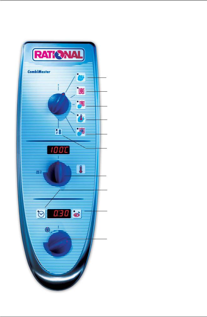
CM Control Panel
Steam (100°C / 212°F)
Hot Air (30°C — 300°C / 86 — 572°F)
Combi Steam (30°C — 300°C / 86 — 572°F)
Low Temp. Steam (30°C — 99°C / 86 — 210°F)
Finishing (30°C — 300°C / 86 — 572°F)
Cool Down
 Cabinet temperature display
Cabinet temperature setting
Timer Set-Temp. -control
Gas: Reset key
Core temperature Set-Temp. -control
 Timer — Core temperature display
Timer — Core temperature dial

CM
CM Technique
B1 F4
B3
S2
B5
F3
M1
M4
S3
B2
Y1 Y2
|
B1 |
Thermocouple cabinet |
|
B2 |
Thermocouple quenching / Steam control |
|
B3 |
Thermocouple core temperature |
|
B5 |
Thermocouple steam generator (preheating, 180°C (356°F) max) |
|
F3 |
Safety temperature limiter steam generator 160°C / 320°F |
|
F4 |
Safety temperature limiter cabinet 360°C / 680°F |
|
Y1 |
Solenoid valve lling |
|
Y2 |
Solenoid valve quenching |
|
M1 |
Fan motor (without jumper) |
|
M4 |
Pump SC-Automatic |
|
S2 |
Level electrode |
|
S3 |
Door contact switch |
|
CM 201/202 only: |
|
|
M2 |
Fan motor top (with jumper) |

CM
Water level control Steam Generator
|
S2 |
||
|
B5 |
||
|
F3 |
||
|
M4 |
||
|
B2 |
||
|
Y1 |
Y2 |
|
|
Center S2 ==> Ground: |
2 — 6V AC: |
water level too low
steam heating must switch OFF solenoid valve lling Y1 ON
|
Center S2 ==> Ground: |
0V AC: |
water level reached |
||||||||||||
|
steam heating can switch ON |
||||||||||||||
|
solenoid valve lling Y1 switched OFF |
||||||||||||||
|
Every 2 minutes steam elements will switch off for |
PCB |
|||||||||||||
|
water level control |
||||||||||||||
|
1 |
2 |
3 |
4 |
|||||||||||
|
X12 |
||||||||||||||

CM
RATIONAL SC Automatic
During the production of steam, the concentration of minerals inside the steam generator will increase over time. These minerals settle on the heating elements and heat exchanger as well as the interior steam generator walls.
In order to reduce this effect the steam generator will be pumped off and ushed regularly depending on the duration of steam production. This process needs approximately 45 seconds.
After emptying the steam generator it will be lled automatically with fresh water.
There are 4 conditions to start this SC Automatic:
1.Heating time of the steam generator must exceed 60 min.* (SCC Care Control: 120min) and
2.the temperature of the thermocouple inside steam generator (B5) must be below 65°C (149°F) and
3.the temperature of the thermocouple inside interior cabinet (B1) must be below 70°C (158°F) and
4.the unit is switched ON.
* — can be adjusted from 20-120min
In case the unit is used permanently the above mentioned temperature conditions can not be met.
In this case the following 2 conditions apply:
1.The heating time of the steam generator reaches the twice the set duration*, i.e. 120 min. and
2.the unit door is open for longer than 30 seconds
After completion of the SC-Automatic the accumulated steam heating time is re-set to zero.
SC-Automatic does not replace the need for descaling and/or installing water treatment lter
![]()
CM
Steam Control CM
Intelligent steam control via quenching sensor
1.Filling of interior cabinet based on time and temperature control of B2 quenching sensor; (cabinet if fully lled with steam and all surfaces have reached steam temperature).
B1
B2
|
Y2 |
|||
|
Y1 |
|||
B1
B2
|
Y2 |
|||
|
Y1 |
|||
Temp.
B1 — 100°C(212°F)
70°C
(158°F)
2.After steam saturation inside cabinet steam will also ll quenching chamber
3.After reaching quenching temperature (B2) quenching solenoid Y2 will be activated.
Depending on the frequency of temperature raise of the quenching sensor B2 the duration of the next steam supply is calculated.
B2 temperature with partial load
B2 temperature with full load
4.The amount of steam inside the cabinet is directly depending on the temperature variation of quenching sensor B2.
t (s)

CM
Additional functions CM
Below are listed the additionaly functions for the user / operator:
1.Cleaning program
1)Cool down cabinet below 60°C / 140°F
2)Spray inside cabinet with Rational cleaner
3)Close cabinet door
4)Select „Cool Down
5)Press core temperature key for 10 sec.
6) „CLEn“ will show in cabinet temperature display
7) Press timer key 1x; Cleaning program starts automatically (open cabinet door and rinse interior cabinet after 40 min.) Close door again. Since Software version C1-06-05 a 10 min step hot air will follow to dry the interior cabinet.
 After end of program, leave cabinet door open over night.
2. Empty steam generator
This should be done after each installation to verify free drain connection and prior to disconnection the unit for storage.
1)Open cabinet door
2)Select „Cool Down“
3) Press core temperature key for 10 sec.
4) „CLEn“ will be shown in cabinet temperature display
5) Select „SC“ with temperature dial
6) Close water tap
7) Press timer key 1x and remain on „Cool Down“ position for about 45 sec.
3.Descaling program
1)Open cabinet door
2)Select „Cool Down“
3) Press core temperature key for 10 sec.
4) „CLEn“ will be shown in cabinet temperature display
5) Select „CALC“ with temperature dial
6) Press timer key 1x and follow procedure of the decalci cation instruction. (See user manual CM).

CM
Additional functions CM
4.Changing temperature display from °C to °F
1)Select any mode
2) Press timer and core temperature key simultaneously for 10 sec. until Display changes from °C to °F or vice versa
3) Release both keys
Aborting of descaling program CM:
—Switch unit off and on again
—press core temperature key 1x
—remaining time of 20 minutes will be displayed. During this time the steam generator will be
ushed and the unit will be operated in steam mode for a couple of minutes to eliminate all remaining chemical residues.

CM
CM PCB
|
42.00.004 from 04-2004 |
—- 42.00.047 from 02-2006 |
|
42.00.004 |
X2 B3 Core temperature |
Transformer
X7
X19
1
X20
1
X3 B1 Interior cabinet
X4 B2 Quenching / Steam control
X6 B5 Steam generator
X7 ON — OFF switch
42.00.047
|
2 AT |
|||||||
|
X16 |
F6 |
||||||
|
2 AT |
|||||||
|
F6.1 |
X7 |
||||||
|
X19 |
|||||||
|
1 |
|||||||
|
X20 |
|||||||
|
1 |
|||||||
|
X18 |
|||||||
|
X63 |
X23 |
||||||
|
1 |
|||||||
|
1 |
X31 |
||||||
|
off |
3 2 |
on |
X30 |
RS 485 |
|||
|
4 |
RS 232 |
||||||
|
X8 |
|||||||
|
Temperatur |
X12 |
||||||
|
1 |
|||||||
|
Poti |
|||||||
|
X26 |
|||||||
|
X50 |
X27 |
||||||
|
1 |
|||||||
|
X2 |
X6 |
X4 |
X3 |
||||
|
1 |
X24 |
1 |
X32 |
X8 Buzzer
X12 Level electrode
X 16 power supply from transformer (42.00.047)
X18 SC — pump
X19 Solenoid valves
X20 Energy management system / Sicotronic
X23 Vent hood (signal door open / closed)
X24 SSR
X26 SSR pulsing (USA version only)
X27 Door contact switch
X30 Serial interface (RS232)
X31 BUS interface
X32 Timer / Core Temp. Potentiometer
X50 external EEPROM
X63 Not used
1Counting sequence
Since February 2006 PCB 42.00.004 is replaced by 42.00.047. (Conversion kit: 87.00.139, pls. see Technical info 04-2006)
The transformer on the new PCB 42.00.047 is no more existing and replaced by external transformer 40.00.227

CM
Fan motor 40.00.274

 Jumper
LED
Jumper 40.01.581 is used on oor model 201 and 202 for top position motor only! Jumper is not used on models 61 — 102 with one motor only!
If jumper is not set correctly E12 will be displayed!
LED code fan motor SCC and CM from 04/2004
|
Reason |
Remedy |
|
|
1x |
Motor doesn’t start, no changing |
Check for motor blockage or change motor. |
|
signal from hallsensor |
||
|
2x |
Voltage too low on motor pcb |
Check supply voltage or |
|
change motor. |
||
|
3x |
Voltage too high on motor pcb |
Check supply voltage or |
|
change motor. |
||
|
4x |
rpm measurement defective |
Change motor. |
|
5x |
Motor pcb temperature >105°C |
Check cooling system (cooling fan, air |
|
intake lter), otherwise change motor |
||
|
6x |
Supply voltage <80V |
Check power supply |
|
(F1-F2) |
||
|
7x |
Motor pcb defective |
Change motor. |
|
8x |
Motor pcb defective |
Change motor. |
Units 3AC400-480V (without neutral) are equipped with motor 40.00.276 (3-phase supply)
This motor is equipped with a 4 pole plug for the supply voltage.

CM
CM — Sequence of events
Mode: Steam 100°C (212°F), Temp. preset, not adjustable
B1 F4
B3
S2
B5
F3
M1
M4
S3
B2
Y1 Y2
|
Function Step |
Responsible sensor |
1.Select Steam mode
2.Select time or core temperature
|
3. |
Close cabinet door |
Reed switch S3 |
|||
|
4. |
Check water level inside steam generator |
Level electrode S2 inside Steam Generatorr |
|||
|
5. |
Time based preheating of steam generator, |
Thermocouple B5 inside Steam Generator |
|||
|
if B5 is below 85°C (185°F); |
|||||
|
6. |
Timer starts after successful preheating |
Logic on PCB |
|||
|
(blinking dot in Display) |
|||||
|
7. |
Steam supply up to steam saturation |
Quenching sensor B2 |
|||
|
inside cabinet |
(Steam control) |
||||
|
8. |
Hot Air supply (only 50%) when set |
Cabinet sensor B1 |
|||
|
temperature (100°C/212°F) can not be |
|||||
|
reached in time by Steam alone |
|||||
|
9. |
Quenching (set to 70°C/158°F) |
Quenching sensor B2 |
|||

CM
CM — Sequence of events
Mode: Low temperature steam; Temp. range 30-99°C (86-210°F)
B1 F4
B3
S2
B5
F3
M1
M4
S3
Function Step Responsible sensor
1.Select Low temperature steam mode Set temperature 30-99°C (86-210°F)
2.Select time or core temperature
|
3. |
Close cabinet door |
Reed switch S3 |
|
4. |
Check water level inside steam generator |
Level electrode S2 inside Steam Generatorr |
|
5. |
Time based preheating of steam generator, |
Thermocouple B5 inside Steam Generator |
|
if B5 is below 85°C (185°F); |
||
|
6. |
Timer starts after successful preheating |
Logic on PCB |
|
(blinking dot in Display) |
||
|
7. |
Steam supply until set temperature |
Cabinet sensor B1 |
|
inside cabinet is reached |
||
|
8. |
Hot Air supply (only 50%) when set |
Cabinet sensor B1 |
|
temperature can not be reached in time |
||
|
by Steam alone |
||
|
9. |
Quenching (set to 70°C/158°F) |
Quenching sensor B2 |
Note: Reduction of fan motor speed
In case the actual temperature is 2°C / 4°F higher than the set temperature for longer than 2 minutes, the fan speed will be reduced automatically.

CM
CM — Sequence of events
Mode: Combination; Temp. range 30-300°C (86-572°F)
B1 F4
B3
S2
B5
F3
M1
M4
S3
B2
Y1 Y2
|
Function Step |
Responsible sensor |
1.Select Combi mode
Set temperature 30-300°C (86-572°F)
2.Select time or core temperature
|
3. |
Close cabinet door |
Reed switch S3 |
|
4. |
Check water level inside steam generator |
Level electrode S2 inside Steam Generatorr |
|
5. |
Time based preheating of steam generator, |
Thermocouple B5 inside Steam Generator |
|
if B5 is below 85°C (185°F); |
||
|
6. |
Timer starts after successful preheating |
Logic on PCB |
|
(blinking dot in Display) |
||
|
7. |
Hot Air supply until set temperature |
Cabinet sensor B1 |
|
inside cabinet. Hot air has priority |
||
|
8. |
Steam supply up to steam saturation |
Quenching sensor B2 |
|
inside cabinet |
(Steam Control) |
|
|
9. |
Quenching (set to 70°C/158°F) |
Quenching sensor B2 |
Note: Reduction of fan motor speed
In case the actual temperature in the range of 30-99°C (86 — 210°F) is 2°C / 4°F higher than the set temperature for longer than 2 minutes, the fan speed will be reduced automatically.

CM
CM — Sequence of events
 F
F 
Mode: Finishing; Temp. range 30-300°C (86-572°F)
B1 F4
B3
S2
B5
F3
M1
M4
S3
B2
Y1 Y2
|
Function Step |
Responsible sensor |
1.Select Finishing mode
Recommended temperature 30-300°C (86-572°F)
2.Select time or core temperature
|
3. |
Close cabinet door |
Reed switch S3 |
|
4. |
Check water level inside steam generator |
Level electrode S2 inside Steam Generator |
|
5. |
Time based preheating of steam generator, |
Thermocouple B5 inside Steam Generator |
|
if B5 is below 85°C (185°F); |
||
|
6. |
Timer starts after successful preheating |
Logic on PCB |
|
(blinking dot in Display) |
||
|
7a. |
Electric units: alternating |
|
|
12 sec. Hot Air |
Cabinet sensor B1 |
|
|
6 sec. Steam |
Quenching sensor B2 |
|
|
7b |
Gas units: alternating |
|
|
30 sec. Hot Air |
Cabinet sensor B1 |
|
|
15 sec. Steam |
Quenching sensor B2 |
|
|
8. |
Quenching (set to 70°C/158°F) |
Quenching sensor B2 |
Note: Reduction of fan motor speed
In case the actual temperature in the range of 30-99°C (86 — 210°F) is 2°C / 4°F higher than the set temperature for longer than 2 minutes, the fan speed will be reduced automatically.

CM
CM — Sequence of events
Mode: Hot Air; Temp. range 30-300°C (86-572°F)
B1 F4
B3
S2
B5
F3
M1
M4
S3
Function Step Responsible sensor
1.Select Hot Air mode
Set temperature 30-300°C (86-572°F)
2.Select time or core temperature
|
3. |
Close cabinet door |
Reed switch S3 |
|
4. |
Timer starts immediately |
Logic on PCB |
|
5. |
Hot Air supply unitl set temperature |
Cabinet sensor B1 |
|
is reached |
||
|
6. |
Quenching (set to 90°C/194°F) |
Quenching sensor B2 |
Note: Reduction of fan motor speed
In case the actual temperature in the range of 30-99°C (86-210°F) is 2°C / 4°F higher than the set temperature for longer than 2 minutes, the fan speed will be reduced automatically.
![]()
CM
Failure Codes CM
The following error codes are shown to the operator:
For showing information of the cabinet display press core temperature key
|
Time |
Cabinet |
Failure explanation |
Description / remedy |
||
|
display |
display |
||||
|
H2O open |
Lack of water / open water tap |
||||
|
Change Polarity |
Phase / Neutral (only gas units) |
||||
|
Reset Gas |
Flame detection after ignition faulty |
||||
|
external EEPROM |
Not initialised |
||||
|
Timeout of external |
Heating blocked by the extern. energy- |
||||
|
power optimising system |
optimising system for longer 2 min. |
||||
|
B1 Interior cabinet sensor |
Sensor broken |
||||
|
B2 Quenching sensor |
Sensor broken |
||||
|
B3 Core sensor |
Sensor broken |
||||
|
B5 Sensor steam generator |
Sensor broken |
||||
|
Thermocouple on PCB |
Sensor broken |
||||
|
Poti interior cabinet |
Defective |
||||
|
Poti timer/core temperature |
Defective |
||||
|
external EEPROM |
Defective |
||||
|
Mode switch |
After 5 sec switching on the unit, a |
||||
|
cooking mode couldn‘t be identi ed |
|||||
|
Fan motor 1 (bottom) |
St = Status (probably Motor defect) |
||||
|
Fan motor 1 (bottom) |
|||||
|
Fan motor 2 (top) |
Co = Communication, (Bus failure) |
||||
|
Fan motor 2 (top) |
|||||
|
M4 SC-pump |
Mal function |
||||
|
Solenoid valve lling Y1 |
|||||
|
(failure can only occur during the |
Mal function |
||||
|
descaling program) |
|||||
|
PCB temperature |
above 85°C (185°F) |
||||
|
Steam generator |
Temperature B5 above 180°C (356°F) |
||||
|
Steam generator |
Temperature B5 below -5°C (23°F) |
||||
|
Interior cabinet temp. |
Temperature B1 above 340°C (644°F) |
||||
|
Free |
|||||

CM
Failure Codes CM (cont.)
For showing information of the cabinet display press core temperature key
|
Time |
Cabinet |
Failure explanation |
Description / remedy |
|
|
display |
display |
|||
|
Ignition box 1 |
||||
|
Ignition box 2 |
Ignition box does not reply, Bus failure |
|||
|
Ignition box 1 Steam |
Ignition box defective (change box) |
|||
|
Ignition box 1 Hot air |
||||
|
Ignition box 2 Hot air |
||||
|
Ignition box 1 Steam |
Testing of ignition and monitoring |
|||
|
Ignition box 1 Hot air |
||||
|
necessary |
||||
|
Ignition box 2 Hot air |
||||
|
Free |
||||
|
Actual data structure of the EEPROM |
||||
|
EEPROM |
does not match with the software; flash |
|||
|
pcb first |
||||

CM
|
Service level CM |
|||||||
|
1) |
Switch unit ON |
||||||
|
2) |
On operator PCB set DIP switch 1 to „ON“ position |
||||||
|
on |
|||||||
|
1 |
2 |
3 |
4 |
||||
|
3) |
Select service package with timer dial: |
||||||
|
Diagnostic Program |
|||||||
|
Error code history |
|||||||
|
Running times |
|||||||
|
Basic settings |
|||||||
|
4) |
Activate with core temperature key the desired service package |
||||||
|
5) |
Select with timer dial the desired step |
||||||
|
6) |
Activate selected step by pressing timer key |
||||||
|
on |
7) |
To de-activate service package set DIP switch 1 to „OFF“ position. |
|||||
|
3 |
|||||||
|
1 |
2 |
4 |
Function Test
|
1) |
Switch unit ON |
|||||
|
on |
2) |
On operator PCB set DIP switch 3 to „ON“ position |
||||
|
1 |
2 |
3 |
4 |
|||
|
First step of function test is displayed. |
||||||
|
3) |
Select desired step of function test with timer dial |
|||||
|
4) |
Activate preselected step by pressing timer key |
|||||
|
5) |
Activate selected function step with core temperature key |
|||||
|
on |
6) To de-activate function test set DIP switch 3 to „OFF“ position. |
|||||
|
1 |
2 |
3 |
4 |
|||
42.00.004
Transformer
X7
X19
1
X20
1
42.00.047
|
2 AT |
||
|
X16 |
F6 |
|
2 AT
F6.1
X63 
|
X7 |
|
|
X19 |
|
|
1 |
|
|
X20 |
|
|
1 |
|
|
X18 |
|
|
X23 |
|
|
1 |
|
|
X31 |
|
|
X30 |
RS 485 |
|
RS 232 |
|
|
X8 |
|
|
X12 |
|
|
1 |
|
X26 |
||
|
X50 |
X27 |
|
|
1 |
||
X2 X6 X4 X3
|
1 |
X24 |
1 |
X32 |
||||

CM
Service level: dP — Diagnostic Program
|
Description |
Connection |
Cabinet |
Time display |
||||
|
Display |
|||||||
|
Software Version |
Software |
Software |
|||||
|
Version: C — 1 |
07.01 |
||||||
|
B1 Cabinet sensor |
X 3 |
actual value |
max value |
Reset by pressing |
|||
|
for 5 sec. |
+ |
||||||
|
B2 Quenching sensor |
X 4 |
actual value |
max value |
Reset by pressing |
|||
|
for 5 sec. |
+ |
||||||
|
B3 Core sensor |
X 2 |
actual value |
max value |
Reset by pressing |
|||
|
for 5 sec. |
|||||||
|
+ |
|||||||
|
B5 Steam generator |
X 6 |
actual value |
max value |
Reset by pressing |
|||
|
sensor |
for 5 sec. |
+ |
|||||
|
PCB temperature |
actual value |
max value |
Reset by pressing |
||||
|
for 5 sec. |
+ |
||||||
|
S3 Door contact |
X27:(1-2) |
1 — 0 |
0 = door open |
||||
|
1 = door closed |
|||||||
|
S2 Water level steam |
X12:(1-4) |
S2 |
S2: 0 — 1 |
Y1: 1 — 0 |
|||
|
generator |
X19:(1-3) |
Y1 |
|||||
|
Steam elements |
actual Temp. |
0 — 1 — 2 |
|||||
|
0 — off; 1 — 50%; 2 — 100% |
B5 |
||||||
|
Hot Air elements |
actual Temp. |
0 — 1 — 2 |
|||||
|
0 — off; 1 — 50%; 2 — 100% |
B1 |
||||||
|
Speed fan motor bottom |
BUS |
Set rpm |
actual rpm |
||||
|
Speed fan motor top |
BUS |
Set rpm |
actual rpm |
only oor model |
|||
|
201/202 |
|||||||
|
Energy management |
X 20 |
1 — 0 |
|||||
|
(Sicotronic) |
|||||||
|
SSR control (US version) |
X24 |
1 — 0 |
0 = US version only |
||||
|
Unit size and type |
61 — 202 |
ELE — GAS |
|||||
|
Flame current Steam |
x.x A* |
since SW Version: |
|||||
|
C1-06-05 ( ame current) |
|||||||
|
Flame current Hot air |
Hot air top |
since SW Version: |
|||||
|
top |
x.x A* |
C1-06-05 ( ame current) |
|||||
|
Flame current Hot air |
Hot air bottom |
since SW Version: |
|||||
|
bottom |
x.x A* |
C1-06-05 ( ame current) |
|||||
*With SW Version C1-06-05 the ame current will show as 20-24 A
(This value must be divided by 4 to get the correct ame current e. g. 22:4 = 5,5 A.) Starting with SW version C1-07-01 the actual ame current is shown .

CM
Service Level: ER — Error code history
Since software version C1-07-01 the last 10 general error messages are shown (applies for electric and gas models)
|
Er |
When timer key is pressed the error code will be displayed. i.e.: |
|
|
Error number |
Error Code |
Description |
|
Er1 |
3 |
B1 Cabinet sensor defective |
|
Er2 |
14 |
Y1 Filling solenoid defective |
|
Er3 —- ER10 |
Gas error GE: (gas units only!)
Since software version C1-07-01 the last 16 gas error messages (GE11 — GE26) are shown in addition to the general error messages. These error codes are generated by the ignition box
|
Error number |
Error Code |
Description |
|
GE11 |
20 |
No rpm signal |
|
GE12 |
32 |
No ame after 5 ignition sequences |
|
GE13 — GE26 |
Indication of ignition box error messages (1-32 is shown to the operator as „rES“):
|
1 |
Hot air or Steam |
no gas, gas valve or electrode defective |
|
|
14 |
Hot air |
gas valve control, change ignition box |
|
|
19 |
Hot air |
no ame because ame current is too low |
|
|
check burner setting, ame current, ignition cable and plug |
|||
|
20 |
Hot air |
wrong or no rpm signal from gas blower |
|
|
check gas blower, power supply gas blower and control harness of gas blower |
|||
|
22 |
Hot air |
no ame after 5 ignition sequences |
|
|
no gas, gas valve or electrode defective |
|||
|
24 |
Steam |
gas valve control, change ignition box |
|
|
29 |
Steam |
no ame because ame current is too low |
|
|
check burner setting, ame current, ignition cable and plug |
|||
|
30 |
Steam |
wrong or no rpm signal from gas blower |
|
|
check gas blower, power supply gas blower and control harness of gas blower |
|||
|
32 |
Steam |
no ame after 5 ignition sequences |
|
|
no gas, gas valve or electrode defective |
|||
|
Possible failure in case of „E21“ |
|||
|
33, 36 |
Change ignition box |
||
|
35 |
Check frequency of main |
||
|
39 |
Hot air |
Check burner setting, ignition electrode and distance, and ame current |
|
|
40 |
Hot air |
Check ignition cable |
|
|
42 |
Steam |
Check burner setting, ignition electrode and distance, and ame current |
|
|
43 |
Steam |
Check ignition cable |
|
|
Is shown on display „CHnG PoL“ |
|||
|
34 |
Change polarity of mains |
All other numbers (2-13, 15-18, 21, 23, 25-28, 31): change ignition box

CM
Service Level: rt — Running Time
|
Description |
Timer display: 1-999 |
Comment |
||||
|
Temp. display: >1000 |
||||||
|
Total S3 door openings |
number |
Reset by pressing |
+ |
|||
|
for 5 sec. |
||||||
|
Total |
time Y1 valve lling |
min |
Reset by pressing |
+ |
||
|
for 5 sec. |
||||||
|
Total |
time Y2 valve quenching |
min |
Reset by pressing |
+ |
||
|
for 5 sec. |
||||||
|
Total time M4 SC-pump |
min |
Reset by pressing |
+ |
|||
|
for 5 sec. |
||||||
|
Total |
time steam heating time |
hrs |
Reset by pressing |
+ |
||
|
for 5 sec. |
||||||
|
Total |
time hot air heating time |
hrs |
Reset by pressing |
+ |
||
|
for 5 sec. |
||||||
|
Total time steam mode |
hrs |
Can not be reset |
||||
|
Total |
time hot air mode |
hrs |
Can not be reset |
|||
|
Total |
time combination mode |
hrs |
Can not be reset |
|||
|
Total |
time vario steam mode |
hrs |
Can not be reset |
|||
|
Total |
time nishing mode |
hrs |
Can not be reset |
|||
|
Total |
time cleaning program |
hrs |
Can not be reset |
|||
|
Total running time unit |
hrs |
Can not be reset |
||||

CM
Service level: SE — Basic settings
Switch unit OFF and ON again after any changes made!
Select desired step with timer dial
(fan motor and heating elements are automatically OFF)
Activate selected step with timer key
|
Steam heating time since last SC-Automatic |
|
|
Press time and core key simultaneously for 5 seconds to set steam heating time |
|
|
+ |
(SE2) to preset steam heating time plus 1 minute (default 45+1min) => test function |
|
for SC-Automatic |
Preset Steam heating time until SC-Automatic (default 60min)
Press time key and adjust preset steam heating time from 20 — 120 minutes with timer
dial
 +
+
Flushing time SC-Automatik (default 45 seconds)
Press time key and adjust ushing time of SC-Automatik from 30 — 90 seconds with
timer dial
 +
+
Operation SC pump (oFF — continuous or on — pulsing)
Press time key and select „on“ or „oFF“ with timer dial
 +
+
Press time key and select „on“ or „oFF“ with timer dial
 +
+
Setting new gas type (G20, G25, G30, G31, 13A)
Press time key, keep it pressed and select new gas type with timer dial
|
Con rm new gas type by pressing core temperature key once. |
||
|
+ |
Corresponding gas blower speed is automatically adjusted |
|
|
NOTE: After changing gas type a waste gas analysis must be carried out in the func- |
||
|
tion test. |
Presetting of CO2 screw in mm on gas valve after gas type modi cation / changing gas valve
Press time key, keep it pressed and select with timer dial “ST“ for steam, “HA1“ for
+hot air top or “HA2“ for hot air bottom (only 201/202) with timer dial; Average lenght in mm of CO2 screw on gas valve is shown on timer display

CM
Service level: SE — Basic settings
Adjustment of installation altitude above sea level (since SW C1-06-05) — 500m — 4500m
|
+ |
Press time key, keep it pressed and select installaton altitude in 500m steps by timer |
|
dial. Con rm altitude setting by pressing simultaneously core temperature key once |
Adjusting speed of blower motor steam (+/ -10%)
(After blower speed adjustment the original rpm is shown in the temp. display, the changed rpm is shown in the time display)
|
Press time key, keep it pressed and adjust displayed rpm with timer dial |
|
|
+ |
SE9 = MIN rpm; SE10 = Start rpm; SE11 = MAX rpm |
|
NOTE: After changing speed of blower motor a waste gas analysis MUST be carried |
|
|
out in the function test. |
Adjusting speed of blower motor hot air top (+/ -10%)
(After blower speed adjustment the original rpm is shown in the temp. display, the changed rpm is shown in the time display)
|
Press time key, keep it pressed and adjust displayed rpm with timer dial |
|
|
+ |
SE12 = MIN rpm; SE13 = Start rpm; SE14 = MAX rpm |
|
NOTE: After changing speed of blower motor a waste gas analysis MUST be carried |
|
|
out in the function test. |
Adjusting speed of blower motor hot air bottom (+/ -10%)
(After blower speed adjustment the original rpm is shown in the temp. display, the changed rpm is shown in the time display)
|
Press time key, keep it pressed and adjust displayed rpm with timer dial |
|
|
+ |
SE15 = MIN rpm; SE16 = Start rpm; SE17 = MAX rpm |
|
NOTE: After changing speed of blower motor a waste gas analysis MUST be carried |
|
|
out in the function test. |
|

CM
Service level: F — Function test
NOTE: In Function test components are NOT protected against overload! Set DIP switch 3 to „ON“ position!
|
Function |
Connection |
Cabinet |
Time |
Comment |
||
|
PCB |
display |
display |
||||
|
Steam 50%, |
actual temp.B5 |
Gas: |
||||
|
Electric unit |
X24:(1-2) |
1 / 0 |
||||
|
steam generator |
no function |
|||||
|
Steam 100% |
X24:(1-2)+(5-6) |
actual temp.B5 |
1 / 0 |
Gas: |
||
|
Electric unit |
steam generator |
no function |
||||
|
Hot air 50% |
X24:(7-8) |
actual temp.B1 |
1 / 0 |
Gas: |
||
|
Electric unit |
cabinet |
no function |
||||
|
Hot air 100% |
X24:(7-8)+(3-4) |
actual temp.B1 |
1 / 0 |
Gas: |
||
|
Electric unit |
cabinet |
no function |
||||
|
Steam Gas unit |
BUS |
actual temp.B5 |
1 / 0 |
Electric: |
||
|
B5 Dampfgenerator |
no function |
|||||
|
Hot air top |
BUS |
actual temp.B1 |
1 / 0 |
Electric: |
||
|
Gas unit |
cabinet |
no function |
||||
|
Hot air bottom |
BUS |
actual temp.B1 |
1 / 0 |
Electric: |
||
|
Gas unit |
cabinet |
no function |
||||
|
Bottom Motor MAX |
BUS |
Set rpm |
Act. rpm |
|||
|
rpm |
||||||
|
Bottom Motor MIN |
BUS |
Set rpm |
Act. rpm |
|||
|
rpm |
||||||
|
Top Motor |
BUS |
Set rpm |
Act. rpm |
|||
|
MAX rpm |
||||||
|
Top Motor |
BUS |
Set rpm |
Act. rpm |
|||
|
MIN rpm |
||||||
|
Solenoid valve |
X19:(2-4) |
actual temp. |
Y2 |
|||
|
quenching |
B2 quenching |
1 / 0 |
||||
|
Solenoid valve |
X19:(1-3) |
Level electrode |
Y1 |
|||
|
lling |
S2, 1 / 0 |
1 / 0 |
||||
|
SC Pump |
X18:(1-2) |
M4 |
Level electrode |
M4 |
||
|
X12:(1-4) |
S2 |
S2, 1 / 0 |
1 / 0 |
|||
|
Buzzer |
X8:(1-2) |
1 / 0 |
||||
|
All Displays / LED |
||||||
|
Relais Ultravent |
only existing with |
|||||
|
(door open |
X 23: (1-2-3) |
1 / 0 |
||||
|
connected UV |
||||||
|
/ close) |
||||||
|
no function |
||||||

CM
Service Level: F — Function Test
Note: In function test components are NOT protected against overload! Set DIP switch 3 to „ON“ position!
|
Function |
Connection |
Cabinet |
Time |
Comment |
||
|
I/O pcb |
display |
Display |
||||
|
Gas blower Steam |
BUS |
actual rpm |
Set CO2 |
Check CO2 value |
||
|
MIN rpm |
||||||
|
Gas blower Steam |
BUS |
actual rpm |
||||
|
Start rpm |
||||||
|
Gas blower Steam |
BUS |
actual rpm |
Set CO2 |
Adjust CO2 value with |
||
|
MAX rpm |
CO2 screw |
|||||
|
Gas blower Hot air top |
BUS |
actual rpm |
Set CO2 |
Check CO2 value |
||
|
MIN rpm |
||||||
|
Gas blower Hot air top |
BUS |
actual rpm |
||||
|
Start rpm |
||||||
|
Gas blower Hot air top |
BUS |
actual rpm |
Set CO2 |
Adjust CO2 value with |
||
|
MAX rpm |
CO2 screw |
|||||
|
Gas blower Hot air bottom |
BUS |
actual rpm |
Set CO2 |
Check CO2 value |
||
|
MIN rpm |
||||||
|
Gas blower Hot air bottom |
BUS |
actual rpm |
||||
|
Start rpm |
||||||
|
Gas blower Hot air bottom |
BUS |
actual rpm |
Set CO2 |
Adjust CO2 value with |
||
|
MAX rpm |
CO2 screw |
|||||
![]()
CM
Software update CM units
1 General
To update a CM unit of new generation you need:
—CM-Software e.g. C-1-07.01.hex
—software „Megaload.zip“.
Both are available on the Rational Service internet page under: „Technical documentation/Software update SCC-Line/CM“.
—download CM-Software e.g.“C-1-07.01.hex“
—download „megaload.zip“ to PC,
—open le„megaload.zip“,
—Start the program Setup.exe and follow the description on the screen,
—Start the program Megaload and carry out basic settings.
 Open CM Software; e.g.: C-1-07.01.hex
Select desired interface on the PC, e.g. Com1
Transfer rate must be set to 19200 bps.
On the „Message“ window the progress of the download
 software download is indicated.
Now You can load the software:
— direct from PC to CM unit, (see item 4 next page) or
— with Flash-Box 87.00.037 to CM unit, (see following items 2, 3).
|
2 Load software to Flash-Box |
|
|
Flash-Box kit contains of: |
— Open lid of the |
|
— Flash-Box |
Flash-Box |
|
— Adapter cable RS 232 |
— Set DIP — switch |
|
and USB-cable |
2 to „ON“. (other |
|
(only required for down |
switches remain in |
|
loading the unit soft- |
the „OFF“ position) |
|
ware to the Flash-Box). |
—Connect RS 232 adapter cable to Flash-Box and to the selected interface (e. g. COM 1) of the PC.
—Connect USB-cable to Flash-Box and PC.
—After the USB cable was connected the les which are transferred will appear on the Message window. An end sign indicates that the transfer is completed.
—On the Flash-Box set DIPswitch 2 to „OFF“ and 3 to „ON“ (the other switches remain „OFF“). Flash-Box is ready for use.

CM
3 Copy software from ash box to unit:
—Switch off unit with mode switch and open control panel;
—Connect RS 232 interface of CM pcb with ash box;
—Switch CM unit on. Displays of pcb remain off. Green LED of ash box starts blinking.
—After successful uploading the CM pcb will switch on; the green LED on theash box stops blinking and remains on continuously.
—Switch unit off and disconnect ash box.
—Unit is ready for operation;
4 Load software via PC to CM unit:
—Switch off unit with mopde switch and open control panel
—Connect RS 232 interface of CM pcb with standard RS 232 cable to PC.
—Switch CM unit on. Displays of pcb remain off. The transfer status will be displayed in a message window.
—After successful uploading the CM pcb will switch on;
—Switch unit off;
—Close megaload program and disconnect RS 232 cable.
—Unit is ready for operation;
To connect via USB adapter the driver must be installed on the PC. Set driver with the following setting:
Bit: 9600 Data bit: none Parity: 8 Stop bit: none
Flow control: none
Connect USB cable with ash box and PC Start Megaloader
Connect null modem cable with ash box and USB Adapter
After connecting the USB cable the download is shown in the display window.
|
42.00.004 |
42.00.047 |
|||
|
0,1 AT |
2 AT |
|||
|
F1 |
F2 |
|||
|
Transformer |
X16 |
|||
|
X7 |
||||
|
0,1 AT |
||||
|
X19 |
F6.1 |
|||
|
X20 |
||||
|
X63 |
||||
|
off |
1 |
no |
RS 232 |
|
|
43 2 |
no |
|||
|
X30 |
RS 232
X50
X2 X
X24 X3

CM
Fault tree: Changing CM pcb / replace EEPROM
2 reasons to follow below procedure:
—Changing of pcb (software version on replacement pcb is not known)
—Unit display „E1“ — replace external memory with new EEPROM
Disconnect unit from power supply (Remove fuses F1 and F2)
Replace new PCB
Note:
Do NOT connect external EEPROM as software version of pcb might not be compatible with pcb without updating!
Reconnect unit from power supply ( x fuses F1 and F2 back)
Software update of pcb to
C1-07-01 or later
Disconnect unit from power supply (Remove fuses F1 and F2)
Reconnect EEPROM to pcb
Reconnect unit from power supply ( x fuses F1 and F2 back)
|
Error „E1“ still existing |
OK |
Call Rational Service

CM


SCC
Comparing display of software version
|
Display up to software version |
Display since software version |
|
SCC 01-07-12 |
SCC 02-01-01 |
13:45

SCC
Display since software version SCC 02-01-01
|
SelfCooking Control |
SelfCooking Control |
SelfCooking Control |
||
|
Level 1 |
Level 2 |
Level 3 |
|
1 |
||||||
|
roast |
braise |
|||||
|
2 |
||||||
|
roast with |
soft |
|||||
|
crackling |
roasting |
|||||
|
3 |
||||||
|
overnight |
soft cooking |
|||||
|
roasting |
||||||
overnight roasting
|
low |
high |
|||||||||
medium 62°C
|
4 |
4 |
13:45 |
4 |
close |
|
13:45 |
||||
|
door |
||||
Large roast
Pan fries
Poultry
Fish
Side dishes
Potato product
Egg dishes/Desserts
Bakery products Finishing
Back to previous level
CleanJet, HACCP, Delta T, E1/2
Start time, CDS, Descaling, Settings
Selection of core temperature
Help: guide line for selected setting; practical hints for product to be used in the respective SCC cooking process
Store selected setting
Searing

SCC
Display since software version SCC 02-01-01 to 03-01-05
|
Combi Steamer mode |
Setting of humidity |
|
Setting of |
cabinet temperature |
|||
|
1 |
Setting of |
time |
||
|
0% 10% 20% 30% 40% 50% 60% 70% 80% 90% 100% |
Setting of |
core temperature |
||
|
2 |
||||
|
200°C |
E |
Moistening |
||
|
3 |
Setting of fan speed (lowest level=intermittent) |
|||
|
continous |
||||
|
4 |
Cool Down |
|||
|
Function level |
E no link on I/O X20 |
|||
|
No 230V on I/O X21 |
Function level
CleanJet CleanJet programs
Delta -T cooking — 1/2 Energy
1
CleanJet
Telephone Chef-Line, delete all programs, program lock, buzzer setting, time setting
|
2 |
setting start time |
|||||
|
Start time |
Start time |
|||||
|
3 |
Download and upload of unit data like customer |
|||||
|
programs, HACCP and service data |
||||||
Service level
Settings Settings
|
Settings |
am/pm |
Setting of |
time format |
|||||||||||||||
|
24 h |
||||||||||||||||||
|
h:m |
Setting of |
time laps |
||||||||||||||||
|
m:s |
||||||||||||||||||
|
1 |
08/22/03 |
Setting of |
date format |
|||||||||||||||
|
am/pm |
h:m |
22.08.03 |
||||||||||||||||
|
10:24 |
24 h |
|||||||||||||||||
|
m:s |
Setting of |
°C/°F |
||||||||||||||||
|
2 |
°C / °F |
|||||||||||||||||
|
10/22/06 |
°C / °F |
|||||||||||||||||
|
IP |
Setting of |
language |
||||||||||||||||
|
22.10.06 |
english |
|||||||||||||||||
reset to factory setting
english, °C, buzzer perm., h:min
buzzer, Setting of buzzer sound
|
IP Adress |
Setting of display intensity |
|||||||
|
actual time |
Setting CleanJet request |
|||||||
|
10:24 |
IP |
|||||||
|
(only active when frame shows in red) |
||||||||

SCC
Display since software version SCC 02-01-01 to 03-01-05
|
1 |
Service Info: Display of pending service faults |
||||||||||||||||||||||||||||||||||||||||||||
|
Service Info |
|||||||||||||||||||||||||||||||||||||||||||||
|
2 |
Descale |
Descaling program: automatic process |
|||||||||||||||||||||||||||||||||||||||||||
|
Descale |
empty steam generator (Door must be open!) |
||||||||||||||||||||||||||||||||||||||||||||
|
3 |
|||||||||||||||||||||||||||||||||||||||||||||
|
CDS |
CDS |
Display of scale level inside steam generator |
|||||||||||||||||||||||||||||||||||||||||||
|
4 |
|||||||||||||||||||||||||||||||||||||||||||||
|
Typ |
Typ |
Display of software version |
|||||||||||||||||||||||||||||||||||||||||||
1
No: E11SE0707200………
2
SW: SCC — 03 — 01 — 04
3
Mod: SCC_101
4
English
|
No: E11SE0707200…. |
Serial number |
SW: SCC — 03 — 01 — 04 Software version
Mod: SCC_101 — Model and size
humidity emergency control currently active
humidity emergency control was active since last switch ON (will not be displayed when in „dry heat mode“)
|
English |
selected language |
|
1 |
Chef |
Line |
||
|
Chef |
Line |
|||
|
2 |
Prog |
|||
|
Prog |
||||
|
h:m |
||||
|
m:s |
3h:m
Display phone number of Chef-hotline
erase all customer programs
Setting time in hours/minutes (h:m) or minutes/seconds (m:s)
setting buzzer (sound-duration)
setting existing SCC process or program can be copied and get an index number, i.e. 1; name can be edited and changed; „Program lock“
Password: 12345; TTREU

SCC
Data downloading
 Prog
Prog
 Prog
Prog 
 Prog
Prog
 HACCP
HACCP
 update
 Info
Info
 P, H, I 05, S05
Copy customer program to stick
Reload customer programs from stick to unit
Erase customer programs
Download of HACCP-Data
Software updates (Icon only shows when unit detects valid software on the USB stick)
Download of service data to stick.
Only shows when USB stick is connected
Programming
Prog
new
|
1 |
||||||||||
|
Roast |
||||||||||
|
2 |
copy |
|||||||||
|
new |
level |
|||||||||
|
control |
||||||||||
|
3 |
||||||||||
|
copy |
change |
change |
||||||||
4
erase
erase
level control
Select customer program with central dial
Give program name
(blank — between _ and @ sign)
existing SCC process or program can be copied and get an index number, i.e. 1; name can be edited and changed;
Change parameter and / or cooking mode of program in a non-active program;
con rm change by:
selected program ashes; con rm delete by pressing again;
1.Give program name
2.Store
3.select mode, temperature, time (in minutes and seconds) or core temperature,
4.Additional program with identical mode and temperature, but different time can be stored and selected alternating after pre-heating;
![]()
|
CleanJet |
rinse without |
||||||||||||
|
Tabs |
|||||||||||||
|
rinse |
|||||||||||||
|
1 |
|||||||||||||
|
rinse without |
rinse |
||||||||||||
|
interim |
|||||||||||||
|
Tabs |
|||||||||||||
|
cleaning |
|||||||||||||
|
2 |
|||||||||||||
|
interim |
light |
||||||||||||
|
cleaning |
light |
||||||||||||
|
3 |
|||||||||||||
|
medium |
strong |
||||||||||||
|
4 |
medium |
||||||||||||
|
CleanJet |
|||||||||||||
|
strong |
|||||||||||||
Rinse with water only; cabinet will be dried out;
Rinse with 1 tab for cleaning after steaming;
Rinse with 1 cleaner tab for cleaning in between cooking cycles; no drying of cabinet;
Cleaning of light soiling with drying of cabinet
Cleaning of medium soiling with drying of cabinet
Cleaning of strong soiling with drying of cabinet
Indicated number of tabs can be changed from software 03-01-01!
If unit shows Servcie 25 check if water hits the left rack at levels 3-4. Refer to fault tree at end of manual.
Interrupting CleanJet programs
—A CleanJet program can only be interrupted by switching the unit off and back on again.
—After restarting the unit “CleanJet interrupt” is shown and the buzzer sounds for 20 seconds.
—If the interrupt key was not touched within 20 seconds, then the CleanJet program continuous
—If the interrupt key was touched, then the interrupt program starts. Next the request for removing the tabs is coming up.
—After the door was opened and closed again, then the interrupt program starts with a duration of 10 minutes
—The interrupt program can also be aborted by switching the unit of and back on again. In this case cabinet must be rinsed manually and by pressing the arrow back key the cleanjet function can be stopped
Interrupting descaling program SCC:
As long as no descaler was lled into the steam generator the „Arrow back“ in window 1 is still showing.
After the descaler was con rmed to be lled the only way to interrupt the descaling process is to:
—Switch unit OFF and ON againPress „Abort“
—Remaining time of 1:08 will be displayed
—If now the key „Aborted“ is pressed again and the unit is switched OFF and ON again a remaining time of 23 min will show.
—After another 2 min this time display will drop to 5 min
—Now the steam generator will be ushed 2x. After this the „Arrow Back“ will be shown.
—By touching this key the descaling program will be exited
Note: Rinse the cabinet thoroughly with fresh water and operate the unit in steam mode for some minutes.
— Now the unit can be accessed for cooking again.

SCC
Display Unit Index “E” since software version SCC 04-01-01
Function level
1
2
3
Settings
4
CleanJet CleanJet programs
Telephone Chef-Line, delete all programs, program lock, buzzer setting, time setting
setting start time
Download and upload of unit data like customer programs, HACCP and service data
Service level
Settings
|
Settings |
am/pm |
|||
|
24 h |
||||
|
h:m |
||||
|
m:s |
||||
|
1 |
08/22/03 |
|||
|
am/pm |
h:m |
22.08.03 |
||
|
10:24 |
||||
|
24 h |
||||
|
m:s |
°C |
|||
|
2 |
°C |
°F |
||
|
10/22/06 |
IP |
|||
|
22.10.06 |
°F |
english |
||
Setting of time format
Setting of time laps
Setting of date format
Setting of °C/°F
Setting of language
reset to factory setting
english, °C, buzzer perm., h:min
buzzer, Setting of buzzer sound
|
actual time |
IP Adress |
Setting of display intensity |
||||||||||
|
10:24 |
IP |
|||||||||||
|
Setting CleanJet request |
||||||||||||
|
Half energy |
||||||||||||
|
(only active when frame shows in red) |
||||||||||||
|
Chef Line |
Display phone number of Chef-hotline |
2
Prog 
erase all customer programs
Setting time in hours/minutes (h:m) or minutes/seconds (m:s)
setting buzzer (sound-duration)
3h:m
|
m:s |
Prog |
Prog setting existing SCC process or program can be |
|||||||||||||
|
copied and get an index number, i.e. 1; name can |
|||||||||||||||
|
4 |
be edited and changed; „Program lock“ |
||||||||||||||
|
Password: 12345; TTREU |
|||||||||||||||
|
only possible with manual mode selected |
|||||||||||||||

SCC
Display Index “G” since software version SCC 04-01-01
|
Combi Steamer mode |
Setting of humidity |
|
Setting of |
cabinet temperature |
|||||||
|
1 |
Setting of |
time |
||||||
|
0% 10% 20% 30% 40% 50% 60% 70% 80% 90% 100% |
Setting of |
core temperature |
||||||
|
2 |
||||||||
|
200°C |
||||||||
|
E |
Moistening |
|||||||
|
3 |
Setting of fan speed (lowest level=intermittent) |
|||||||
|
continous |
||||||||
|
4 |
Cool Down |
|||||||
|
Function level |
E no link on I/O X20 |
|||||||
|
No 230V on I/O X21 |
||||||||
|
Function level |
Indication of care status |
|||||||
|
CareControl |
||||||||
|
CleanJet |
+ care |
CleanJet programs |
||||||
|
1 |
Telephone Chef-Line, delete all programs, |
|||||||
|
CareControl |
program lock, buzzer setting, time setting |
|||||||
|
2 |
+ care |
Start time setting start time |
||||||
|
CleanJet |
Start time |
|||||||
|
3 |
Download and upload of unit data like customer |
|||||||
|
Settings |
programs, HACCP and service data |
|||||||
|
4 |
Service level |
|||||||
|
Settings |
Settings |
|||||||
|
Settings |
am/pm |
|||
|
24 h |
||||
|
h:m |
||||
|
m:s |
||||
|
1 |
08/22/03 |
|||
|
am/pm |
h:m |
22.08.03 |
||
|
10:24 |
||||
|
24 h |
||||
|
m:s |
°C |
|||
|
2 |
°C |
°F |
||
|
10/22/06 |
IP |
|||
|
22.10.06 |
°F |
english |
||
Setting of time format
Setting of time laps
Setting of date format
Setting of °C/°F
Setting of language
reset to factory setting
english, °C, buzzer perm., h:min
buzzer, Setting of buzzer sound
|
actual time |
IP Adress |
Setting of display intensity |
||||||
|
10:24 |
IP |
|||||||
|
Setting CleanJet request |
||||||||
|
Half energy |
||||||||
|
(only active when frame shows in red) |
||||||||

SCC
Display Cleanjet +Care Index “G” (10-2008)
Software SCC 04-01-01
CareControl 

|
CleanJet |
rinse without |
Rinse with water only; cabinet will be dried out; |
|
Air Baf e Tabs |
||
|
tab for cleaning after steaming; |
Care Container
1
2
light
3
4
strong soiling with drying of cabinet
Intelligent cleaning process: The unit recognizes automatically the likely soiling of the cabinet using the data of used cooking programs, cooking temperatures and running times.
CDS


Cleanjet demand
The customer usage (based on used cooking programs, cooking temperatures and running times) determines the number of red bars in the display “Cleanjet demand” ==> Intelligent cleanjet process.
If all bars show in red, “Care Control” is displayed.
CDS display
The number of pulses of the CDS sensor determines the number of red bars in the CDS display.
If the customer always uses the recommended Care tabs when using cleanjet, the steam generator will stay free of scale and the display will not change to red bars.

SCC
SCC Electric — Basic principle
B1 F4
 B6 — B11
|
M3 |
|
|
S4 |
|
|
S2 |
|
|
B5 |
P1 |
|
F3 |
|
|
M1 |
|
|
B4 |
|
|
M4 |
|
Care |
|||||||||||||||||||||||||||||||||||
|
S3 |
|||||||||||||||||||||||||||||||||||
|
M12 |
|||||||||||||||||||||||||||||||||||
|
Y3 |
Y4 |
||||||||||||||||||||||||||||||||||
|
Y1 |
|||||||||||||||||||||||||||||||||||
|
S11 |
B2 |
||||||||||||||||||||||||||||||||||
|
Y2 |
|||||||||||||||||||||||||||||||||||
|
M6 |
|||||||||||||||||||||||||||||||||||
|
S12 |
|||||||||||||||||||||||||||||||||||
|
M7 |
|||||||||||||||||||||||||||||||||||
|
B1 |
Thermocouple interior cabinet |
||||||||||||||||||||||||||||||||||
|
B2 |
Thermocouple quenching |
||||||||||||||||||||||||||||||||||
|
B4 |
Thermocouple humidity |
||||||||||||||||||||||||||||||||||
|
B5 |
Thermocouple steam generator (preheat, 180°C (356°F) max) |
||||||||||||||||||||||||||||||||||
|
B6-B11 |
Thermocouples core temperature |
||||||||||||||||||||||||||||||||||
|
F3 |
Safety thermostat steam generator 160°C (320°F) |
||||||||||||||||||||||||||||||||||
|
F4 |
Safety thermostat interior cabinet 360°C (680°F) |
||||||||||||||||||||||||||||||||||
|
Y1 |
Solenoid valve lling |
||||||||||||||||||||||||||||||||||
|
Y2 |
Solenoid valve quenching |
||||||||||||||||||||||||||||||||||
|
Y3 |
Solenoid valve moistening |
||||||||||||||||||||||||||||||||||
|
Y4 |
Solenoid valve care |
||||||||||||||||||||||||||||||||||
|
M1 |
Fan motor bottom |
||||||||||||||||||||||||||||||||||
|
M3 |
Humidity ap motor |
||||||||||||||||||||||||||||||||||
|
M4 |
SC-pump |
||||||||||||||||||||||||||||||||||
|
M6 |
CleanJet pump |
||||||||||||||||||||||||||||||||||
|
M7 |
Motor drain valve / ball valve |
||||||||||||||||||||||||||||||||||
|
M12 |
Care pump |
||||||||||||||||||||||||||||||||||
|
S2 |
Level electrode |
||||||||||||||||||||||||||||||||||
|
S3 |
Door reed switch |
||||||||||||||||||||||||||||||||||
|
S4 |
Micro switch humidity motor |
||||||||||||||||||||||||||||||||||
|
S11 |
CDS sensor |
||||||||||||||||||||||||||||||||||
|
S12 |
Micro switch drain valve |
||||||||||||||||||||||||||||||||||
|
P1 |
Pressure sensor humidity |
||||||||||||||||||||||||||||||||||
|
SCC 201/202 only: |
|||||||||||||||||||||||||||||||||||
|
M2 |
Fan motor top with jumper ( oor units only) |

SCC
Parts identification (no CareControl)
|
17 |
||
|
19 |
||
|
1 |
20 |
|
|
3 |
18 |
|
2
21
4
|
6 |
||
|
5 |
||
|
7 |
||
|
8 |
||
|
10 |
22 |
|
|
9 |
||
|
11 |
13 |
|
|
12 |
||
|
14 |
16
|
1 |
12 |
|
|
2 |
13 |
|
|
3 |
14 |
|
|
4 |
15 |
|
|
5 |
16 |
|
|
6 |
17 |
|
|
7 |
18 |
|
|
8 |
19 |
|
|
9 |
20 |
|
|
10 |
21 |
|
|
11 |
22 |

SCC
Parts identi cation CareControl
1
2
1
2
3
3
3
1
2
3
4
11
4
4
11

SCC
General information to software version SCC 04-01-01
Software SCC 04-01-01 can also be used for units with index „E“ (from 04-2004).
With this software you have the following options:
Using the button “Cleanjet request” you can select the “Intelligent Cleanjet request”. In this case the cleanjet request will be based on used cooking programs, tempratures and cooking duration.
Selecting Cleanjet you will see the below symbol in window 4 of your display:
The second setting to choose is Cleanjet request based on cooking time only (as known from older software versions).
In order to deselect the Cleanjet request (turn symbol from red to blue again) select time functions and setb time to “0”..
In Service Mode Basic Settings position 26 you select „Softwater“ ON to indicate only the half amount of detergent tabs when cleanjet is choosen. The individual tab setting (as available since software SCC 03-01-01) is no more existing.
Software SCC 04-01-01 in units with index „G“ (from 10-2008)
Basic Settings 26 „Softwater“
In Service Mode Basic Settings position 26 you select „Softwater“ ON to indicate only the half amount of detergent tabs when cleanjet is choosen.
Basic Settings 28 „Selftest“:
After installation the unit will ask the user to start a Selftest. Water MUST be connected!
After the Clima Control valve and the drain valve have initialised the steam generator will ll, SC pump will start shortly and Y1 will re ll again.
In case the temperatures of B1, B2 and B4 are below 40°C now “Start” will be displayed.
After pressing “Start” the unit will adapt to the present installation conditions (duration appr. 15 min). Should the unit be installed later at a different location, this “Selftest” can be re-initialised by setting “Selftest” to ON in basic settings position 28.
Basic Settings 29 „Warranty“:
After rst switch on the unit will prompt the customer to register and validate his second year warranty online under www.rational-ag.com/warranty.
This prompting will discontinue after 4 days.
After registration a warranty certi cate will be issued:
In case the unit was installed in a show room or exhibition, this prompting can be re-initialised by setting “Warranty” to ON in basic settings position 29.
Basic Settings 30 „Steam corrosion control“
The unit automatically recognises if the customer used it predominantely in steam mode. In case this usage is more than 90% during the last 20 hours of operation the unit will prompt a Cleanjet request daily regardless of the total duration of cooking time
Basic Settings 31 „Care Control Reset“
By setting the switch to “ON” all Care Control bars will be set to blue.

SCC
Controling the SC pump and solenoid valves before starting the cleanjet process:
If the Cleanjet Start key is pressed the unit will check rst for the proper function of the SC pump and the solenoid valves.
The SC pump is operated shortly until the level electrode shows low water. In case of failure “Servcie 10” is displayed and Cleanjet can not be started. Y1 lling solenoid valve is started, function checked by CDS sensor
In case of failure “Low Water” will be indicated
Y3 moistening solenoid valve is started, function checked by CDS sensor In case of failure Service 41
Y4 care solenoid valve is started, function checked by CDS sensor In case of failure Service 42
All solenoid valves are switched off, CDS shall not send any pulses; In case of failure Service 43
New Service Error codes
Service 40
Care pump faulty or does not ll enough care solution into steam generator;
—After lling of the care solution into the steam generator the CDS sensor sends too many pulses until the level electrode recognises water.
—Cleanjet nishes without care phase;
—Reset by successfull completion of Cleanjet process;
Service 41
—Solenoid valve Y3 defective or moistening nozzle blocked; CDS does not send any pulses;
—Reset error by successfull CDS measuring during next Cleanjet start;
Service 42
—Solenoid Y4 Care defective or hose to care container vlocked or kinked; CDS does not send any pulses;
—Reset error by successfull CDS measuring during next Cleanjet start;
Service 43
—CDS sensor sends always pulses; Solenoid Y1, Y3 or Y4 is passing water
—Reset error by successfull CDS measuring during next Cleanjet start (Self test)
Service 44
—No temperature raise during recognised by B5 during steaming time while being in Cleanjet phase
—Reset error by successfull B5 tempoerature measuring during next Cleanjet;
Service 110
—Malfunction of SC pump during the time when Care solution was inside the steam generator,
—Reset error by successfull completing a cleanjet abort cycle;
Service 120
—After operating care pump M12 ( lling care solution into steam generator) and topping up with water (Y1) the level electrode does not recognise water;
—Y1 or level electrode defective;
—Display only after twice starting lling solenoid Y1 yet no water is detected;
—Reset error by successfull completing a cleanjet abort cycle;

SCC
It is possible to abort the cleanjet program. However the abort program of 30min. can not be shortened again as the steam generator must be neutralised from possible remaining care solution.
Cleanjet Abort program
During the abort program the steam generator will first be filled with Y1. After draining the steam egnerator it will be filled a second time to a level above the level electrode. After a second draining the steam generator will fill again exactly to the level electorde.
In case the level electrode does not recognise the water Error 120 will be shown.
At the end of the abort program a short steam period and rinsing the cabinet with Cleanjet pump will follow.
The duration of steam heating time unitl next SC automatic is now 120min (units with index “G”) . However should the steam generator develop scale because the customer does not use the care tabs, this time will automatically be reset to 60 minutes.
 Loading…
Пароконвектомат бойлерный электрический RATIONAL, серия SelfCookingCenter®, модель SCC 101, артикул B118100.01 – высокотехнологичный, многофункциональный, программируемый и суперсовременный аппарат. Rational SCC 101 отлично подойдет для кафе, ресторанов, столовых, фабрик-кухонь и других общепитов. Камера на 10 уровней загрузки стандарта GN 1/1 (530х325мм), 7 программ автоматической мойки, 6-ти точечный температурный зонд, тройное остекление двери.
Описание пароконвектомата RATIONAL SCC 101
- Рабочие режимы: конвекция: +30…+300 °; пар: +30…+130 °C; комби-режим (пар + конвекция): +30…+300 °C.
- iCookingControl — 7 программ: мясо, птица, рыба, гарниры, блюда из яиц, выпечка, Finishing® для простого ввода желаемых результатов с автоматической настройкой идеального процесса приготовления.
- Предварительные настройки в соответствии с национальными предпочтениями.
- iCC Cockpit — графический обзор текущего микроклимата в рабочей камере, предполагаемого дальнейшего процесса приготовления, а также опций в конце приготовления.
- iCC-Messenger — информирует о текущих, автоматических настройках процесса приготовления.
- iCC-Monitor — обзор всех автоматических настроек процесса приготовления.
- Режим записи — определение идеального цикла приготовления в зависимости от температуры внутри эталонных продуктов для последующего использования без термозонда, с автоматическим учетом объёма загрузки.
- Возможность сохранения до 1200 пользовательских программ, до 12 шагов приготовления в каждой.
- Термозонд с 6 точками измерения. Вспомогательное позиционирующее устройство для зонда.
- Поуровневая сигнализация: iLC — указывает на то, какой уровень можно загружать или разгружать; iCC или ручной режим — сигнализация с помощью светодиодного освещения об окончании фазы прогрева или окончании процесса, Efficient CareControl — сигнализация с помощью светодиодного освещения о завершении мойки.
- Функция автоматического охлаждения камеры.
- iLC-Messenger — информация о текущих, автоматических настройках приготовления.
- ClimaPlus Control® — измерение, настройка и регулировка влажности с точностью до процента. Высокоэффективное удаление влаги из рабочей камеры с помощью вакуумной технологии для поджаристой хрустящей корочки.
- Автоматические процессы Finishing® для режима «тарелки для банкета», для обслуживания фуршетов, à la carte и т. д.
- Низкотемпературное (Су-Вид) и ночное приготовление.
- Приготовление по разнице Дельта-T для щадящего приготовления больших кусков мяса.
- 5 программируемых уровней расстойки теста.
- Цифровая индикация температуры. Выбор шкалы: в °C или °F.
- Часы реального времени, 24 часа. Цифровой таймер, 0–24 часа, с постоянной настройкой. Выбор формата отображения времени: часы/минуты или минуты/секунды.
- Энергоэффективность: режим энергосбережения: 1/2 энергии (для электрических моделей); регулировка подачи энергии в соответствии с потреблением; счетчик энергопотребления.
- Мощный парогенератор с автоматическим наполнением водой.
- Динамическое перемешивание воздуха с помощью реверсивного 5-ти скоростного вентилятора с встроенным тормозом крыльчатки.
- Сепарация жира методом центрифугирования, без дополнительного жирового фильтра.
- Дверь с тройным стеклом, воздушной прослойкой и теплоотражающим покрытием. Внутреннее стекло открывается для удобной очистки.
- Дверной каплесборник с подключением к водоотводу.
- Аварийное оповещения при открытой дверце.
- Гигиеничная рабочая камера без стыков, со скругленными углами.
- Энергосбергающее светодиодное освещение рабочей камеры и уровней загрузки.
- Рабочие и предупреждающие сообщения, например, о нехватке воды.
- Предохранительные ограничители температуры для бойлера и камеры.
- Дверная ручка с функцией захлопывания и открывания вправо/влево, открывается одной рукой.
- Разъем USB для вывода данных HACCP и сервисных данных, а также для передачи программ приготовления на карту памяти USB и для обновления программного обеспечения.
- Интерфейс Ethernet, например для использования приложения RATIONAL Remote, системы RATIONAL ConnectedCooking, подключения к системе управления кухней или для вывода данных HACCP.
- Сертификаты: Сертификат кошерности, CE, VDE, UL, CUL, DEKRA, IRAM, EAC, EMC, GS, NSF, EN1717, HCV-EU, SVGW, KIWA, WRAS, Germanischer Lloyd, SVGW, TZW.
Интеллектуальные функции RATIONAL SelfCookingCenter®
- HiDensityControl® (патент) — высокоэффективная, система динамического перемешивания воздуха и подачи и распределения энергии в рабочей камере.
- iCookingControl® (патент) — интеллектуальное приготовление: аппарат распознает размер, количество и состояние продуктов и корректирует рабочие настройки.
- iLevelControl – автоматическое определение идеального микроклимата. Смешанные загрузки с индивидуальным контролем каждого уровня в зависимости от вида и объёма продуктов, а также частоты открывания дверцы.
- Efficient CareControl (патент) — система контролирующая загрязнения рабочей камеры, а также уровня накипи в бойлере. Семь режимов автоматической мойки.
Управление пароконвектоматом RATIONAL SCC 101
- Цветной TFT-дисплей и антибликовый сенсорный экран с интуитивно понятной символикой обеспечивают максимальную простоту в обслуживании, угол обзора до 80 ° гарантирует оптимальную видимость информации на дисплее.
- Меню на 59 языках.
- Самообучающаяся система управления настраивается с учетом действий пользователя.
- Автоматический список Top 10 из десяти наиболее часто используемых программ iCookingControl и iLC.
- Функция MySCC для индивидуальной настройки в соответствии с потребностями того или иного пользователя и его программ: (до 9 профилей пользователей; стартовая страница настраивается с учетом требований пользователя; конфигурирование панели управления (тексты, загрузка изображений и т.д.); настройки энергопотребления; освещение камеры; настройка звуковых сигналов; и многие другие возможности).
- Центральный регулятор с функцией «Push» для настроек и подтверждения ввода данных.
- Блокировка управления и программирования, настраиваемая пользователем (3 ступени).
- Контекстные справки для быстрого доступа.
- Руководство пользователя и эксплуатации с примерами.
- Возможность управления двумя аппаратами SelfCookingCenter® с одного дисплея.
- Дистанционное управление и контроль аппарата с iPhone / iPad с помощью приложения RATIONAL Remote или ПО ConnectedCooking.
Очистка и уход
- Efficient CareControl — автоматическая система очистки и ухода за рабочей камерой и парогенератором: ( автоматическое определение уровня загрязнения; индикация оптимальной ступени очистки; рекомендации по количеству чистящих таблеток; автоматичсекое удаление накипи; отображение текущего этапа очистки и таймер оставшегося времени).
- Для очистки используются сухие средства в таблетках.
- Настраиваемый график очистки.
- Встроенный ручной душ с возвратным механизмом и регулировкой напора струи.
- Сервисная диагностическая система (SDS) с автоматической индикацией сервисных сообщений.
Некоторые технические параметры RATIONAL SCC 101
- Возможна установка на стол глубиной 700 мм.
- Камера и корпус изготовлены из нержавеющей стали AISI 304 (DIN 1.4301).
- Регулировка высоты ножек.
- Давление воды: 150-600 кПа.
- Труба подачи воды: 3/4″.
- Диаметр сливной трубы: 50 мм.
- Водозащищенность по стандарту IPX 5.
Опции и аксессуары для RATIONAL SCC 101
Чистящие средства
- Очищающие таблетки (100 шт) для всех моделей SelfCookingCenter® RATIONAL, артикул 56.00.210
- Очищающие таблетки Care-Tab (150 шт) для аппаратов SelfCookingCenter® с системой Efficient CareControl RATIONAL, артикул 56.00.562
- Ополаскивающие таблетки (50 шт) Care-Tab для аппаратов SelfCookingCenter® с системой Efficient CareControl RATIONAL, артикул 56.00.211
- Противопенные таблетки (120 шт) для всех моделей SelfCookingCenter® RATIONAL, артикул 56.00.598
- Удалитель накипи, 10 литров RATIONAL, артикул 6006.0110
Опции необходимые для установки и эксплуатации RATIONAL SCC 101
- VarioSmoker –для копчения в пароконвектомате, артикул 60.73.008
- Тележка транспортировочная 61/101, артикул 60.60.020
- Тележка регулируемая по высоте 61/101, артикул 60.60.188
- Подставка открытая без направляющих UG I 61/101 стандартная, артикул 60.30.320
- Подставка открытая без направляющих UG I 61/101 передвижная, артикул 60.30.321
- Подставка закрытая с боков с направляющими UG II 61/101 стандартная, артикул 60.30.328
- Подставка закрытая с боков с направляющими UG II 61/101 передвижная, артикул 60.30.329
- Шкаф-подставка открытая с направляющими GN US III 61/101 стандартная, артикул 60.30.334
- Шкаф-подставка открытая с направляющими GN US III 61/101 передвижная, артикул 60.30.335
- Шкаф-подставка открытая с направляющими GN US III UltraVent 61 стандартная, артикул 60.30.337
- Шкаф-подставка открытая с направляющими GN US III UltraVent 61 передвижная, артикул 60.30.338
- Шкаф-подставка закрытая с направляющими GN US IV 61/101 стандартная, артикул 60.30.344
- Шкаф-подставка закрытая с направляющими GN US IV 61/101 передвижная, артикул 60.30.345
- Стандартный вытяжной зонт 61/101, артикул 60.72.313
- Вытяжной зонт с конденсацией пара UltraVent 61/101, артикул 60.72.320
- Вытяжной зонт с конденсацией пара и фильтром UltraVent Plus 61/101, артикул 60.72.202
- Теплозащитный экран для левой боковой стенки, артикул 60.70.391
Не забудьте подобрать фирменные аксессуары RATIONAL для готовки — гастроемкости, противни и решетки.
Опции устанавливаемые на заводе (необходимо указывать во время заказа)
- Напряжение электропитания отличное от базовой конфигурации.
- Дверца с левым креплением.
- Замок дверцы.
- Морское исполнение.
- Запираемая панель управления.
- Внешний термокерн.
- Внешний термокерн для Sous-Vide.
- 3 внешних термокерна для программ iLevelControl.
- Встроенная система слива жира.
- Морское исполнение.