
-
Драйверы
23
-
Инструкции по эксплуатации
2

Asrock G41M-GS3 инструкция по эксплуатации
(51 страница)
- Языки:Английский
-
Тип:
PDF -
Размер:
981.52 KB
Просмотр

Asrock G41M-GS3 инструкция по эксплуатации
(136 страниц)
-
Тип:
PDF -
Размер:
3.72 MB
Просмотр
На NoDevice можно скачать инструкцию по эксплуатации для Asrock G41M-GS3. Руководство пользователя необходимо для ознакомления с правилами установки и эксплуатации Asrock G41M-GS3. Инструкции по использованию помогут правильно настроить Asrock G41M-GS3, исправить ошибки и выявить неполадки.
-
Page 1: User Manual
G41M-GS3 / G41M-S3 User Manual Version 1.0 Published October 2009 Copyright©2009 ASRock INC. All rights reserved. 1 1 1 1 1…
-
Page 2
(including damages for loss of profits, loss of business, loss of data, interruption of business and the like), even if ASRock has been advised of the possibility of such damages arising from any defect or error in the manual or product. -
Page 3: Table Of Contents
2.7 Jumpers Setup …………… 18 2.8 Onboard Headers and Connectors ……..20 2.9 SATAII Hard Disk Setup Guide ……..24 2.10 Serial ATA (SATA) / Serial ATAII (SATAII) Hard Disks Installation …………..25 2.11 Driver Installation Guide ……….25 2.12 Untied Overclocking Technology ……..25…
-
Page 4: Software Support
4 Software Support ……………………………… 51 4.1 Install Operating System ……….51 4.2 Support CD Information ……….51 4.2.1 Running Support CD ……….51 4.2.2 Drivers Menu …………51 4.2.3 Utilities Menu …………51 4.2.4 Contact Information ……….51…
-
Page 5: Introduction
ASRock’s commit- ment to quality and endurance. In this manual, chapter 1 and 2 contain introduction of the motherboard and step-by-step guide to the hardware installation. Chapter 3 and 4 contain the configuration guide to BIOS setup and information of the Support CD.
-
Page 6: Specifications
1 . 2 1 . 2 Specifications Specifications Specifications Specifications Specifications — Micro ATX Form Factor: 9.6-in x 7.6-in, 24.4 cm x 19.3 cm Platform — LGA 775 for Intel Core 2 Extreme / Core 2 Quad / Core ®…
-
Page 7
— 4 x SATAII 3.0 Gb/s connectors (No Support for RAID and Connector “Hot Plug” functions) (see CAUTION— 1 x ATA100 IDE connector (supports 2 x IDE devices) — 1 x Floppy connector — 1 x Print port header…
-
Page 8
Overclocking may affect your system stability, or even cause damage to the components and devices of your system. It should be done at your own risk and expense. We are not responsible for possible damage caused by overclocking. -
Page 9
USB flash drive or hard drive must use FAT32/16/12 file system. 13. The software name itself – OC DNA literally tells you what it is capable of. OC DNA, an exclusive utility developed by ASRock, provides a conve- nient way for the user to record the OC settings and share with others. -
Page 10: Motherboard Layout
USB 2.0 Header (USB4_5, Blue) North Bridge Controller System Panel Header (PANEL1, Orange) CPU Fan Connector (CPU_FAN1) BIOS SPI Chip 2 x 240-pin DDR3 DIMM Slots Chassis Fan Connector (CHA_FAN1) (Dual Channel: DDR3_A1, DDR3_B1; Blue) Floppy Connector (FLOPPY1) ATX Power Connector (ATXPWR1)
-
Page 11: I/O Panel
100Mbps connection Green 1Gbps connection LAN Port * To enable Multi-Streaming function, you need to connect a front panel audio cable to the front panel audio header. Please refer to below steps for the software setting of Multi-Streaming. For Windows ®…
-
Page 12: Installation
Chapter 2 Installation Chapter 2 Installation G41M-GS3 / G41M-S3 is a Micro ATX form factor (9.6″ x 7.6″, 24.4 x 19.3 cm) motherboard. Before you install the motherboard, study the configuration of your chassis to ensure that the motherboard fits into it.
-
Page 13: Cpu Installation
Before you insert the 775-LAND CPU into the socket, please check if the CPU surface is unclean or if there is any bent pin on the socket. Do not force to insert the CPU into the socket if above situation is found.
-
Page 14
PnP cap to assist in removal. 1. It is recommended to use the cap tab to handle and avoid kicking off the PnP cap. 2. This cap must be placed if returning the motherboard for after service. -
Page 15: Installation Of Heatsink And Cpu Fan
CPU and the heatsink to improve heat dissipation. Ensure that the CPU and the heatsink are securely fastened and in good contact with each other. Then connect the CPU fan to the CPU_FAN connector (CPU_FAN1, see page 10, No.
-
Page 16: Installation Of Memory Modules (Dimm)
DIMMs or the system components. Step 1. Unlock a DIMM slot by pressing the retaining clips outward. Step 2. Align a DIMM on the slot such that the notch on the DIMM matches the break on the slot. notch break…
-
Page 17: Expansion Slots (Pci And Pci Express Slots)
2.6 Expansion Slots (PCI and PCI Express Slots) 2.6 Expansion Slots (PCI and PCI Express Slots) There are 2 PCI slots and 2 PCI Express slots on this motherboard. PCI slots: PCI slots are used to install expansion cards that have the 32-bit PCI interface. PCIE slots: PCIE1 (PCIE x1 slot) is used for PCI Express cards with x1 lane width cards, such as Gigabit LAN card, SATA2 card, etc.
-
Page 18: Jumpers Setup
2-pin jumper (see p.10 No.
Note: CLRCMOS1 allows you to clear the data in CMOS. The data in CMOS includes system setup information such as system password, date, time, and system setup parameters. To clear and reset the system parameters to default setup, please turn off the computer and unplug the power cord from the power supply.
-
Page 19: Fsb1/Fsb2/Fsb3 Jumper
FSB3: 1-2 Overclocking Setting: When you mount a FSB800 or FSB1066 CPU, and try to overclock to FSB1333 (by BIOS setting) you may face the problem, that DRAM frequency will be overclocked very high. Please use jumper to force NB to be strapped at higher frequency, so the DRAM can work at lower frequency.
-
Page 20: Onboard Headers And Connectors
(33-pin FLOPPY1) FLOPPY1 Pin1 (see p.10 No. 20) the red-striped side to Pin1 Note: Make sure the red-striped side of the cable is plugged into Pin1 side of the connector. Primary IDE connector (Blue) (39-pin IDE1, see p.10 No. 7) IDE1…
-
Page 21
HDA to function correctly. Please follow the instruction in our manual and chassis manual to install your system. 2. If you use AC’97 audio panel, please install it to the front panel audio header as below: A. -
Page 22
Though this motherboard provides 4-Pin CPU fan (Quiet Fan) support, the 3-Pin CPU fan still can work successfully even without the fan speed control function. If you plan to connect the 3-Pin CPU fan to the CPU fan connector on this motherboard, please connect it to Pin 1-3. -
Page 23
(see p.10 No. 6) Though this motherboard provides 24-pin ATX power connector, it can still work if you adopt a traditional 20-pin ATX power supply. To use the 20-pin ATX power supply, please plug your power supply along with Pin 1 and Pin 13. -
Page 24: Sataii Hard Disk Setup Guide
Before installing SATAII hard disk to your computer, please carefully read below SATAII hard disk setup guide. Some default setting of SATAII hard disks may not be at SATAII mode, which operate with the best performance. In order to enable SATAII function, please follow the below instruction with different vendors to correctly adjust your SATAII hard disk to SATAII mode in advance;…
-
Page 25: Installation
STEP 2: Connect the SATA power cable to the SATA / SATAII hard disk. STEP 3: Connect one end of the SATA data cable to the motherboard’s SATAII connector. STEP 4: Connect the other end of the SATA data cable to the SATA / SATAII hard disk. 2 . 1 1 2 .
-
Page 26: Introduction
<Del> during the Power-On-Self-Test (POST) to enter the BIOS SETUP UTILITY, otherwise, POST will continue with its test routines. If you wish to enter the BIOS SETUP UTILITY after POST, restart the system by pressing <Ctl> + <Alt> + <Delete>, or by pressing the reset button on the system chassis.
-
Page 27: Navigation Keys
To jump to the Exit Screen or exit the current screen <ESC> 3.2 Main Screen Main Screen Main Screen Main Screen Main Screen When you enter the BIOS SETUP UTILITY, the Main screen will appear and display the system overview G41M-GS3 BIOS SETUP UTILITY OC Tweaker Advanced H/W Monitor…
-
Page 28
System Date [Fri 10/16/2009] Use [+] or [-] to configure system Time. BIOS Version : G41M-S3 P1.00 Processor Type : Intel (R) Core (TM) 2 Duo CPU E6850 @ 3.00GHz (64bit) Processor Speed : 3148MHz Microcode Update : 6FB/B6 Select Screen… -
Page 29: Oc Tweaker Screen
[400MHz DDR3_800], [533MHz DDR3_1066] or [667MHz DDR3_1333]. The configuration options depend on the CPU and memory module you adopt on this motherboard. Please refer to page 8 for the CPU FSB frequency and its corresponding memory support frequency. DRAM Command Rate Use this item to adjust DRAM Command Rate.
-
Page 30
Exit v02.54 (C) Copyright 1985-2003, American Megatrends, Inc. DRAM tCL This controls the number of DRAM clocks for TCL. Min: 5. Max: 10. The default value is [Auto]. DRAM tRCD This controls the number of DRAM clocks for TRCD. Min: 3. Max: 10. The default value is [Auto]. -
Page 31
Ratio CMOS Setting If the ratio status is unlocked, you will find this item appear to allow you changing the ratio value of this motherboard. If the CPU you adopt supports EIST (Intel (R) SpeedStep(tm) tech.), and you plan to adjust the ratio value, please disable the option “… -
Page 32: Advanced Screen
GLTREF Voltage Use this to select GLTREF Voltage. Configuration options: [Auto], [0.67 x Vtt], [0.65 x Vtt], [0.63 x Vtt] and [0.615 x Vtt]. The default value of this feature is [Auto]. Would you like to save current setting user defaults? In this option, you are allowed to load and save three user defaults according to your own requirements.
-
Page 33: Cpu Configuration
Ratio CMOS Setting If the ratio status is unlocked, you will find this item appear to allow you changing the ratio value of this motherboard. If the CPU you adopt supports EIST (Intel (R) SpeedStep(tm) tech.), and you plan to adjust the ratio value, please disable the option “…
-
Page 34
On-Demand Clock Modulation This provides the On-Demand Clock Modulation duty cycle. It indicates the clock on to clock off interval ratio. For example, if you set this option to [75.0% On], your processor will work normally 75% of the time, and spend the other 25% slacking off. -
Page 35: Chipset Configuration
DRAM CH1 G5 (Clocks2) v02.54 (C) Copyright 1985-2005, American Megatrends, Inc. DRAM CH0 RCOMP ODT This controls the number of DRAM CH0 RCOMP ODT. Min: 1. Max: 63. The default value is [Auto]. DRAM CH0 G0 (Data) This controls the number of DRAM CH0 G0 (Data). Min: 1. Max: 15. The default value is [Auto].
-
Page 36
DRAM CH0 G3 (Control2) This controls the number of DRAM CH0 G3 (Control2). Min: 1. Max: 15. The default value is [Auto]. DRAM CH0 G4 (Clocks1) This controls the number of DRAM CH0 G4 (Clocks1). Min: 1. Max: 15. The default value is [Auto]. -
Page 37
This controls the number of DRAM CH0 CLKSET1 SKEW. The default value is [Auto]. DRAM CH0 CMD SKEW This controls the number of DRAM CH0 CMD SKEW. The default value is [Auto]. DRAM CH0 CTRL0 SKEW This controls the number of DRAM CH0 CTRL0 SKEW. The default value is [Auto]. -
Page 38
DRAM CH1 CMD SKEW This controls the number of DRAM CH1 CMD SKEW. The default value is [Auto]. DRAM CH1 CTRL0 SKEW This controls the number of DRAM CH1 CTRL0 SKEW. The default value is [Auto]. DRAM CH1 CTRL1 SKEW This controls the number of DRAM CH1 CTRL1 SKEW. -
Page 39
DVMT/FIXED Memory You are allowed to adjust the shared memory size in this item if you set DVMT Mode Select as [DVMT Mode]. Configuration options: [128MB], [256MB] and [Maximum DVMT]. The option [Maximum DVMT] only appears when you adopt the memory module with 1024MB or above. -
Page 40
OnBoard Lan This allows you to enable or disable the “OnBoard Lan” feature. -
Page 41: Acpi Configuration
Use this item to enable or disable Ring-In signals to turn on the system from the power-soft-off mode. PCI Devices Power On Use this item to enable or disable PCI devices to turn on the system from the power-soft-off mode. PS/2 Keyboard Power On Use this item to enable or disable PS/2 keyboard to turn on the system from the power-soft-off mode.
-
Page 42: Storage Configuration
It allows you to select between [SATA 1, SATA 2, SATA 3, SATA 4], [SATA 1, SATA 3, IDE 1], [IDE 1, SATA 2, SATA 4] and [PATA Only]. If it is set to [SATA 1, SATA 3, IDE 1], then SATAII_2, SATAII_4 will not work. Likewise, if it is set to [IDE 1, SATA 2, SATA 4], then SATAII_1, SATAII_3 will not work.
-
Page 43
[ARMD]: This is used for IDE ARMD (ATAPI Removable Media Device), such as MO. LBA/Large Mode Use this item to select the LBA/Large mode for a hard disk > 512 MB under DOS and Windows; for Netware and UNIX user, select [Disabled] to disable the LBA/Large mode. -
Page 44: Pcipnp Configuration
Use this item to enable or disable the S.M.A.R.T. (Self-Monitoring, Analysis, and Reporting Technology) feature. Configuration options: [Disabled], [Auto], [Enabled]. 32-Bit Data Transfer Use this item to enable 32-bit access to maximize the IDE hard disk data transfer rate. 3.4.5 3.4.5 PCIPnP Configuration 3.4.5…
-
Page 45: Floppy Configuration
Use this item to enable or disable floppy drive controller. Serial Port Address Use this item to set the address for the onboard serial port or disable it. Configuration options: [Disabled], [3F8 / IRQ4], [2F8 / IRQ3], [3E8 / IRQ4], [2E8 / IRQ3].
-
Page 46: Usb Configuration
Parallel Port Mode Use this item to set the operation mode of the parallel port. The default value is [ECP+EPP]. If this option is set to [ECP+EPP], it will show the EPP version in the following item, “EPP Version”. Configuration options: [Normal], [Bi-Directional], and [ECP+EPP].
-
Page 47: Hardware Health Event Monitoring Screen
Hardware Health Event Monitoring Screen Hardware Health Event Monitoring Screen In this section, it allows you to monitor the status of the hardware on your system, including the parameters of the CPU temperature, motherboard temperature, CPU fan speed, chassis fan speed, and the critical voltage.
-
Page 48: Boot Screen
3.6 Boot Screen Boot Screen Boot Screen Boot Screen Boot Screen In this section, it will display the available devices on your system for you to config- ure the boot settings and the boot priority. BIOS SETUP UTILITY Main OC Tweaker…
-
Page 49: Security Screen
Boot From Onboard LAN Use this item to enable or disable the Boot From Onboard LAN feature. Boot Up Num-Lock If this item is set to [On], it will automatically activate the Numeric Lock function after boot-up. Security Screen Security Screen 3.7 Security Screen…
-
Page 50: Exit Screen
When you select this option, it will pop-out the following message, “Dis- card changes?” Select [OK] to discard all changes. Load BIOS Defaults Load BIOS default values for all the setup questions. F9 key can be used for this operation. Load Performance Setup Default (IDE/SATA) This performance setup default may not be compatible with all system configurations.
-
Page 51: Install Operating System
4 . 2 . 4 4 . 2 . 4 C o n t a c t I n f o r m a t i o n C o n t a c t I n f o r m a t i o n…
G41M-GS3
Intel® G41+ ICH7 Chipsets
Product Brief
—Supports FSB1333/1066/800/533 MHz CPUs
—Supports Dual Channel DDR3 1333 (OC)
—Intel® Graphics Media Accelerator X4500, Pixel Shader 4.0, DirectX 10, Max. shared memory 1759MB
—EuP Ready
—PCIE Gigabit LAN
—Supports ASRock Instant Boot, Instant Flash, OC DNA, ASRock OC Tuner (Up to 158% CPU frequency increase)
—Supports Smart BIOS, Intelligent Energy Saver (Up to 20% CPU Power Saving)
—Free Bundle : ASRock Software Suite
The specification is subject to change without notice. The brand and product names are trademarks of their respective companies. Any configuration other than original product specification is not guaranteed.
|
www.asrock.com |
||
|
Detail Specification |
||
|
Platform |
— Micro ATX Form Factor: 9.6-in x 7.6-in, 24.4 cm x 19.3 cm |
|
|
CPU |
— LGA 775 for Intel® CoreTM 2 Extreme / CoreTM 2 Quad / |
|
|
CoreTM 2 Duo / Pentium® Dual Core / Celeron® Dual Core |
||
|
/ Celeron®, supporting Penryn Quad Core Yorkfield and |
||
|
Dual Core Wolfdale processors |
||
|
— Supports FSB1333/1066/800/533 MHz |
||
|
— Supports Hyper-Threading Technology |
||
|
— Supports Untied Overclocking Technology |
||
|
— Supports EM64T CPU |
||
|
Chipset |
— Northbridge: Intel® G41 |
|
|
— Southbridge: Intel® ICH7 |
||
|
Memory |
— Dual Channel DDR3 memory technology |
|
|
— 2 x DDR3 DIMM slots |
||
|
— Supports DDR3 1333(OC)/1066/800 non-ECC, |
||
|
un-buffered memory |
||
|
— Max. capacity of system memory: 8GB |
||
|
Expansion Slot |
— 1 x PCI Express x16 slot |
|
|
— 1 x PCI Express x1 slot |
||
|
— 2 x PCI slots |
||
|
Graphics |
— Intel® Graphics Media Accelerator X4500 |
|
|
— Pixel Shader 4.0, DirectX 10 |
||
|
— Max. shared memory 1759MB |
||
|
— Supports D-Sub with max. resolution up to 2048×1536 |
||
|
@ 60Hz |
||
|
Audio |
— 5.1 CH Windows® VistaTM Premium Level HD Audio |
|
|
(Realtek ALC662 Audio Codec) |
||
|
LAN |
— PCIE x1 Gigabit LAN 10/100/1000 Mb/s |
|
|
— Realtek RTL8111DL |
||
|
— Supports Wake-On-LAN |
||
|
Rear Panel I/O |
I/O Panel |
|
|
— 1 x PS/2 Mouse Port |
||
|
— 1 x PS/2 Keyboard Port |
||
|
— 1 x Serial Port: COM1 |
||
|
— 1 x VGA Port |
||
|
— 4 x Ready-to-Use USB 2.0 Ports |
||
|
— 1 x RJ-45 LAN Port with LED (ACT/LINK LED and |
||
|
SPEED LED) |
||
|
— HD Audio Jack: Line in / Front Speaker / Microphone |
||
|
Connector |
— 4 x SATAII 3.0 Gb/s connectors (No support for RAID |
|
|
and «Hot Plug» functions) |
||
|
— 1 x ATA100 IDE connector (supports 2 x IDE devices) |
||
|
— 1 x Floppy connector |
||
|
— 1 x Print port header |
||
|
— CPU/Chassis FAN connector |
||
|
— 24 pin ATX power connector |
||
|
— 4 pin 12V power connector |
||
|
— Front panel audio connector |
||
|
— 2 x USB 2.0 headers (support 4 USB 2.0 ports) |
||
|
BIOS Feature |
— 8Mb AMI Legal BIOS |
|
|
— Supports «Plug and Play» |
||
|
— ACPI 1.1 Compliance Wake Up Events |
||
|
— SMBIOS 2.3.1 Support |
||
|
— CPU, VCCM, NB, SB,VTT Voltage Multi-adjustment |
||
|
— Supports Smart BIOS |
||
|
Support CD |
— Drivers, Utilities, AntiVirus Software (Trial Version), |
|
|
ASRock Software Suite (CyberLink DVD Suite — OEM |
||
|
and Trial ; Creative Sound Blaster X-Fi MB — Trial) |
||
|
Unique Feature |
— ASRock OC Tuner |
|
|
— Intelligent Energy Saver |
||
|
— Instant Boot |
||
|
— ASRock Instant Flash |
||
|
— ASRock OC DNA |
||
|
— Hybrid Booster: |
||
|
— CPU Frequency Stepless Control |
||
|
— ASRock U-COP |
||
|
— Boot Failure Guard (B.F.G.) |
||
|
Hardware Monitor |
— CPU Temperature Sensing |
|
|
— Chassis Temperature Sensing |
||
|
— CPU Fan Tachometer |
||
|
— Chassis Fan Tachometer |
||
|
— CPU Quiet Fan |
||
|
— Voltage Monitoring: +12V, +5V, +3.3V, Vcore |
||
|
OS |
— Microsoft® Windows® 7 / 7 64-bit / VistaTM / VistaTM 64-bit |
|
|
/ XP / XP 64-bit compliant |
||
|
Certifications |
— FCC, CE |
|
|
— EuP Ready (EuP ready power supply is required) |
||
|
Accessories |
— Quick Installation Guide, Support CD, I/O Shield |
|
|
— 2 x SATA Data Cables (Optional) |
||
-
Page 1: Asrock G41M-GS
1 1 1 1 1 G41M-GS User Ma nual V ersion 1.0 Published July 2009 Copyright©2009 ASRock INC. All rights reserved.[…]
-
Page 2: Asrock G41M-GS
2 2 2 2 2 Copyright Notice: Copyright Notice: Copyright Notice: Copyright Notice: Copyright Notice: No part of this manual may be reproduced, transcribed, transmitted, or translated in any language, in any form or by any means, except duplication of documentation by the purcha ser for ba ckup purpose, without written consent of ASRock Inc. Products[…]
-
Page 3: Asrock G41M-GS
3 3 3 3 3 Contents Contents Contents Contents Contents 1 Introduction 1 Introduction 1 Introduction 1 Introduction 1 Introduction …………………………………………… …………………………………………… …………………………………………… …………………………………………… …………[…]
-
Page 4: Asrock G41M-GS
4 4 4 4 4 4 Software Support 4 Software Support 4 Software Support 4 Software Support 4 Software Support ……………………………………. ……………………………………. ……………………………………. ……………………………………. ……………………………………. 50 50 50 50 50 4.1 Instal[…]
-
Page 5: Asrock G41M-GS
5 5 5 5 5 Chapter 1 Introduction Chapter 1 Introduction Chapter 1 Introduction Chapter 1 Introduction Chapter 1 Introduction Tha nk you for purcha sing ASRock G41M-GS motherboard, a relia ble motherboard produced under ASRock’s consistently stringent quality control. It delivers excellent performa nce with robust design conforming to ASRock’s c[…]
-
Page 6: Asrock G41M-GS
6 6 6 6 6 1.2 1.2 1.2 1.2 1.2 Specifications Specifications Specifications Specifications Specifications Platform — Micro A TX Form Fa ctor: 9.6-in x 7.6-in, 24.4 cm x 19.3 cm CPU — LGA 775 for Intel ® Core TM 2 Extreme / Core TM 2 Quad / Core TM 2 Duo / Pentium ® Dual Core / Celeron ® Dual Core / Celeron ® , supporting Penryn Quad Core Y orkfi[…]
-
Page 7: Asrock G41M-GS
7 7 7 7 7 Connector — 4 x SA T AII 3.0 Gb/s connectors (No Support f or RAID and “Hot Plug” functions) (see CAUTION 8 ) — 1 x A T A100 IDE connector (supports 2 x IDE devices) — 1 x Floppy connector — 1 x Print port header — CPU/Cha ssis F AN connector — 24 pin A TX power connector — 4 pin 12V power connector — Front panel audio connector — 2 x[…]
-
Page 8: Asrock G41M-GS
8 8 8 8 8 CAUTION! 1. This motherboard supports native FSB1333/1066/800 MHz. For normal operation, you do not need to adjust the jumper settings. For speci al overclocking mode, plea se refer to page 19 for proper jumper settings. 2. About the setting of “Hyper Threa ding T echnology”, plea se check page 31. 3. This motherboard supports U ntied[…]
-
Page 9: Asrock G41M-GS
9 9 9 9 9 1 1. Featuring a n adva nced proprietary hardware and software de sign, Intelligent Energy Saver is a revolutionary technology that delivers unparalleled power savings. In other words, it is able to provide excep- tional power saving a nd i mprove power efficiency without sa crificing computing performa nce. Please visit our website f or […]
-
Page 10: Asrock G41M-GS
10 10 10 10 10 1.3 Motherboard Layout 1.3 Motherboard Layout 1.3 Motherboard Layout 1.3 Motherboard Layout 1.3 Motherboard Layout 1 PS2_USB_PWR1 IDE1 CHA_FAN1 SPEAKER1 1 HD_AUDIO1 Intel G41 Chipset CLRCMOS1 PANEL1 HDLED RESET PLED PWRBTN 1 CMOS Battery 8Mb BIOS 1 AUDIO CODEC 19.3cm (7.6 in) 24.4cm (9.6 in) ATX12V1 Super IO FLOPPY1 1 2 4 5 7 6 8 9 1[…]
-
Page 11: Asrock G41M-GS
11 11 11 11 11 1.4 I/O P 1.4 I/O P 1.4 I/O P 1.4 I/O P 1.4 I/O P anel anel anel anel anel 1 PS/2 Mouse Port (Green) 6 Microphone (Pink) 2 USB 2.0 Ports (USB23) 7 USB 2.0 Ports (USB01) * 3 RJ-45 Port 8 V G A Port 4 Line In (Light Blue) 9 COM Port 5 Line Out (Lime) 1 0 PS/2 Keyboard Port (Purple) * T o enable Multi-Stre a ming function, you need to c[…]
-
Page 12: Asrock G41M-GS
12 12 12 12 12 Chapter 2 Installation Chapter 2 Installation Chapter 2 Installation Chapter 2 Installation Chapter 2 Installation G41M-GS is a Micro A TX form fa ctor (9.6″ x 7.6″, 24.4 x 19.3 cm) motherboard. Before you install the motherboard, study the configuration of your cha ssis to ensure that the motherboard fits into it. Make sur[…]
-
Page 13: Asrock G41M-GS
13 13 13 13 13 Lift Lever Up to 90° CPU Marked Corner Socket Marked Corner 2.3 CPU Installation 2.3 CPU Installation 2.3 CPU Installation 2.3 CPU Installation 2.3 CPU Installation For the installation of Intel 775-LAND CPU, plea se follow the steps below . Before you in sert the 775-LAND CPU into the socket, ple a se check if the CPU surface is un[…]
-
Page 14: Asrock G41M-GS
14 14 14 14 14 For proper inserting, ple a se ensure to match the two orientation key notches of the CPU with the two alignment keys of the socket. Step 2-3. Carefully pla ce the CPU into the socket by using a purely vertical motion. Step 2-4. V erify that the CPU is within the socket and properly mated to the orient keys. Step 3. Re move PnP Ca p […]
-
Page 15: Asrock G41M-GS
15 15 15 15 15 2.4 2.4 2.4 2.4 2.4 Installation of CPU Fan and Heatsink Installation of CPU Fan and Heatsink Installation of CPU Fan and Heatsink Installation of CPU Fan and Heatsink Installation of CPU Fan and Heatsink This motherboard is equipped with 775-Pin socket that supports Intel 775-LAND CPU. Plea se adopt the type of heatsink a nd cooling[…]
-
Page 16: Asrock G41M-GS
16 16 16 16 16 2.5 Installation of Memory Modules (DIMM) 2.5 Installation of Memory Modules (DIMM) 2.5 Installation of Memory Modules (DIMM) 2.5 Installation of Memory Modules (DIMM) 2.5 Installation of Memory Modules (DIMM) G41M-GS motherboard provides two 240-pin DDR2 (Double Data Rate 2) DIMM slots, a nd supports Dual Cha nnel Memory T echnology[…]
-
Page 17: Asrock G41M-GS
17 17 17 17 17 2.6 Expansion Slots (PCI and PCI Express Slots) 2.6 Expansion Slots (PCI and PCI Express Slots) 2.6 Expansion Slots (PCI and PCI Express Slots) 2.6 Expansion Slots (PCI and PCI Express Slots) 2.6 Expansion Slots (PCI and PCI Express Slots) There are 2 PCI slots a nd 2 PCI Express slots on this motherboard. PCI slots: PCI slots are us[…]
-
Page 18: Asrock G41M-GS
18 18 18 18 18 2.7 Jumpers Setup 2.7 Jumpers Setup 2.7 Jumpers Setup 2.7 Jumpers Setup 2.7 Jumpers Setup The illustration shows how jumpers are setup. When the jumper ca p is pla ced on pins, the jumper is “Short”. If no jumper ca p is pla ced on pins, the jumper is “Open”. The illustration shows a 3-pin jumper whose pin1 an d pin2 are “S[…]
-
Page 19: Asrock G41M-GS
19 19 19 19 19 Standard Setting: If you adopt below DRAM / CPU configuration on this motherboard, you need to adjust the jumpers. Ple a se follow the instructions below to set up the jumpers. Otherwise, the CPU and memory module may not work properly on this motherboard. DRAM DDR2 533 DDR2 1066 CPU FSB533 FSB1066 FSB1333 Jumper Settings FSB1: 2-3 F[…]
-
Page 20: Asrock G41M-GS
20 20 20 20 20 2.8 Onboard Headers and Connectors 2.8 Onboard Headers and Connectors 2.8 Onboard Headers and Connectors 2.8 Onboard Headers and Connectors 2.8 Onboard Headers and Connectors Onboard headers and connectors are NOT jumpers. Do NOT place jumper ca ps over these hea ders and connectors. Pla cing jumper ca ps over the headers a nd connec[…]
-
Page 21: Asrock G41M-GS
21 21 21 21 21 1. High Definition Audio supports Jack Sensing, but the panel wire on the cha ssis must support HDA to function correctly . Plea se follow the instruction in our ma nual a nd cha ssis manual to in stall your system. 2. If you use AC’97 audio pa nel, plea se install it to the front pa nel audio hea der as below: A. Connect Mic_IN (M[…]
-
Page 22: Asrock G41M-GS
22 22 22 22 22 +5V DUMMY DUMMY SPEAKER 1 GND PWR B TN# PLED- PLED+ DUMMY RESET# GND HDLED+ HDLED- 1 System Pa nel Header This header a ccommodates (9-pin P ANEL1) several system front panel (see p.10 No. 17) functions. Cha ssis Spea ker Header Plea se connect the cha ssis (4-pin SPEAKER 1) speaker to this header. (see p.10 No. 14) Cha ssis Fa n Con[…]
-
Page 23: Asrock G41M-GS
23 23 23 23 23 20-Pin A TX Power Supply Installation A TX 12V Connector Pl ease note that it is necessary (4-pin A TX12V1) to connect a power supply with (see p.10 No. 29) A TX 12V plug to this connector so that it can provides sufficient power. Failing to do so will cause the failure to power up. A TX Power Connector Plea se connect an A TX power […]
-
Page 24: Asrock G41M-GS
24 24 24 24 24 2.9 2.9 2.9 2.9 2.9 SA SA SA SA SA T T T T T AII Hard Disk Setup Guide AII Hard Disk Setup Guide AII Hard Disk Setup Guide AII Hard Disk Setup Guide AII Hard Disk Setup Guide Before installing SA T AII hard disk to your computer , plea se carefully read below SA T AII hard disk setup guide. Some default setting of SA T AII hard disks[…]
-
Page 25: Asrock G41M-GS
25 25 25 25 25 2.10 2.10 2.10 2.10 2.10 Serial A Serial A Serial A Serial A Serial A T T T T T A (SA A (SA A (SA A (SA A (SA T T T T T A) / Serial A A) / Serial A A) / Serial A A) / Serial A A) / Serial A T T T T T AII (SA AII (SA AII (SA AII (SA AII (SA T T T T T AII) Hard Disks AII) Hard Disks AII) Hard Disks AII) Hard Disks AII) Hard Disks Insta[…]
-
Page 26: Asrock G41M-GS
26 26 26 26 26 Chapter 3 BIOS SETUP UTILITY Chapter 3 BIOS SETUP UTILITY Chapter 3 BIOS SETUP UTILITY Chapter 3 BIOS SETUP UTILITY Chapter 3 BIOS SETUP UTILITY 3.1 3.1 3.1 3.1 3.1 Introduction Introduction Introduction Introduction Introduction This section explains how to use the BIOS SETUP UTILITY to configure your system. The BIOS FWH chip on th[…]
-
Page 27: Asrock G41M-GS
27 27 27 27 27 3.1.2 3.1.2 3.1.2 3.1.2 3.1.2 Navigation Keys Navigation Keys Navigation Keys Navigation Keys Navigation Keys Plea se check the following table f or the function descri ption of ea ch navigation key. Navigation Key(s) Function Description / Moves cursor left or right to select Screens / Moves cursor up or down to select items + / — T[…]
-
Page 28: Asrock G41M-GS
28 28 28 28 28 3.3 3.3 3.3 3.3 3.3 Smart Screen Smart Screen Smart Screen Smart Screen Smart Screen In the Smart screen, you ca n load the BIOS setup a ccording to your requirements. BIOS SETUP UTILITY Main Advanced H/W Monitor Boot Security Exit Smart Settings Exit system setup after saving the changes. F 1 0k e yc a nb eu s e d for this operation[…]
-
Page 29: Asrock G41M-GS
29 29 29 29 29 Load Optimized CPU OC Setting This option only a ppears when you adopt E5000 series CPU. Y ou can use this option to load the optiomized CPU overclocking setting. Configuration options: [2.64 GHz], [2.88 GHz], [3.00 GHz], [3.12 GHz] a nd [3.27 GHz]. Plea se note that overclocing may cause da mage to your CPU and motherboard. It shoul[…]
-
Page 30: Asrock G41M-GS
30 30 30 30 30 BIOS SETUP UTILITY CPU Configuration Select Screen Select Item +- Change Option F1 General Help F9 Load Defaults F10 Save and Exit ESC Exit v02.54 (C) Copyright 1985-2005, American Megatrends, Inc. Advanced Boot Failure Guard Spread Spectrum [Enabled] [Auto] Select Screen Select Item +- Change Option F1 General Help F9 Load Defaults […]
-
Page 31: Asrock G41M-GS
31 31 31 31 31 Intel (R) Virtualization tech. When this option is set to [Enabled], a VMM (V irtual Ma chine Architecture) ca n utilize the additional hardware ca pabilities provided by V anderpool T echnology . This option will be hidden if the installed CPU does not support Intel (R) Virtualization T echnology . CPU Thermal Throttling Y ou may se[…]
-
Page 32: Asrock G41M-GS
32 32 32 32 32 3.4.2 3.4.2 3.4.2 3.4.2 3.4.2 Chipset Configuration Chipset Configuration Chipset Configuration Chipset Configuration Chipset Configuration BIOS SETUP UTILITY v02.54 (C) Copyright 1985-2005, American Megatrends, Inc. Chipset Configuration Memory Remap Feature DRAM Frequency Flexibility Option DRAM tCL DRAM tRCD DRAM tRP DRAM tRAS DRA[…]
-
Page 33: Asrock G41M-GS
33 33 33 33 33 DRAM tWR This controls the number of DRAM clocks f or TW R. Min: 3. Max: 15. The default value is [Auto]. DRAM tWTR This controls the number of DRAM clocks for TWTR. Min: 2. M ax: 15. The default value is [Auto]. DRAM tRRD This controls the number of DRAM clocks for TRRD. Min: 2. Max: 15. The default value is [Auto]. DRAM tRTP This c[…]
-
Page 34: Asrock G41M-GS
34 34 34 34 34 DRAM RCOMP STRENGTH Configuration BIOS SETUP UTILITY DRAM RCOMP STRENGTH Settings Select Screen Select Item +- Change Option F1 General Help F9 Load Defaults F10 Save and Exit ESC Exit v02.54 (C) Copyright 1985-2005, American Megatrends, Inc. Advanced Select Screen Select Item +- Change Option F1 General Help F9 Load Defaults F10 Sav[…]
-
Page 35: Asrock G41M-GS
35 35 35 35 35 DRAM CH1 G3 (Control2) This controls the number of DRAM CH1 G3 (Control2). Min: 1. M ax: 15. The default value is [Auto]. DRAM CH1 G4 (Clocks1) This controls the number of DRAM CH1 G4 (Clocks1). Min: 1. Max: 15. The default value is [Auto]. DRAM CH1 G5 (Clocks2) This controls the number of DRAM CH1 G5 (Clocks2). Min: 1. Max: 15. The […]
-
Page 36: Asrock G41M-GS
36 36 36 36 36 DRAM DLL SKEW Settings BIOS SETUP UTILITY DRAM DLL SKEW Settings Select Screen Select Item +- Change Option F1 General Help F9 Load Defaults F10 Save and Exit ESC Exit v02.54 (C) Copyright 1985-2005, American Megatrends, Inc. Advanced Select Screen Select Item +- Change Option F1 General Help F9 Load Defaults F10 Save and Exit ESC Ex[…]
-
Page 37: Asrock G41M-GS
37 37 37 37 37 DRAM CH1 CMD SKEW This controls the number of DRAM CH1 CMD SKEW . The default value is [Auto]. DRAM CH1 CTRL0 SKEW This controls the number of DRAM CH1 CTRL0 SKEW . The default value is [Auto]. DRAM CH1 CTRL1 SKEW This controls the number of DRAM CH1 CTRL1 SKEW . The default value is [Auto]. DRAM CH1 CTRL2 SKEW This controls the numb[…]
-
Page 38: Asrock G41M-GS
38 38 38 38 38 Primary Gra phics Ada pter This allows you to select [Onboard], [PCI] or [PCI Express] a s the boot gra phic ada pter priority . The default value is [PCI]. Share Memory This allows you to set share memory feature. The default value is [Auto]. Configuration options: [Auto], [32MB], [64MB], [128MB] and [256MB]. P A VP Mode Use this op[…]
-
Page 39: Asrock G41M-GS
39 39 39 39 39 DRAM V oltage Use this to select DRAM V oltage. Configuration options: [Auto], [1.794V], [1.851V], [1.908V], [1.965V], [2.029V], [2.086V], [2.144V], [2.201V], [2.314], [2.371V], [2.428V], [2.485V], [2.549V], [2.606V], [2.664V] and [2.720V]. The default value of this feature is [Auto]. NB V oltage Use this to select NB V oltage. Confi[…]
-
Page 40: Asrock G41M-GS
40 40 40 40 40 BIOS SETUP UTILITY ACPI Configuration Select auto-detect or disable the STR feature. Select Screen Select Item +- Change Option F1 General Help F9 Load Defaults F10 Save and Exit ESC Exit v02.54 (C) Copyright 1985-2005, American Megatrends, Inc. Advanced Suspend T o RAM Repost Video on STR Resume Check Ready Bit Restore on AC/Power L[…]
-
Page 41: Asrock G41M-GS
41 41 41 41 41 BIOS SETUP UTILITY IDE Configuration Set [Compatible] when Legacy OS (MS-DOS, Win NT) device is used. Set [Enhanced] when Native OS (Win2000 / XP) is used. v02.54 (C) Copyright 1985-2005, American Megatrends, Inc. Advanced A T A/IDE Configuration [Enhanced] Select Screen Select Item +- Change Option F1 General Help F9 Load Defaults F[…]
-
Page 42: Asrock G41M-GS
42 42 42 42 42 TYPE Use this item to configure the type of the IDE device that you specify. Configuration options: [Not In stalled], [Auto], [CD/D V D], a nd [ARMD]. [Not Installed]: Select [Not Installed] to disable the use of IDE device. [Auto]: Select [Auto] to automatically detect the hard disk drive. After selecting the hard disk information i[…]
-
Page 43: Asrock G41M-GS
43 43 43 43 43 DMA Mode DMA ca pability allows the improved tra nsfer-speed a nd data-integrity for compatible IDE devices. S.M.A.R.T. Use this item to ena ble or disable the S.M.A.R.T . (Self-Monitoring, Analysis, a nd Reporting T echnology) feature. Configuration options: [Disabled], [Auto], [Enabled]. 32-Bit Data T ra nsfer Use this item to ena […]
-
Page 44: Asrock G41M-GS
44 44 44 44 44 3.4.6 3.4.6 3.4.6 3.4.6 3.4.6 Floppy Configuration Floppy Configuration Floppy Configuration Floppy Configuration Floppy Configuration In this section, you may configure the type of your floppy drive. 3.4.7 3.4.7 3.4.7 3.4.7 3.4.7 Super IO Configuration Super IO Configuration Super IO Configuration Super IO Configuration Super IO Con[…]
-
Page 45: Asrock G41M-GS
45 45 45 45 45 BIOS SETUP UTILITY USB Configuration T o enable or disable the onboard USB controllers. Select Screen Select Item +- Change Option F1 General Help F9 Load Defaults F10 Save and Exit ESC Exit v02.54 (C) Copyright 1985-2005, American Megatrends, Inc. Advanced USB Controller USB 2.0 Support Legacy USB Support [Enabled] [Enabled] [Enable[…]
-
Page 46: Asrock G41M-GS
46 46 46 46 46 3.5 3.5 3.5 3.5 3.5 Hardware Health Event Monitoring Screen Hardware Health Event Monitoring Screen Hardware Health Event Monitoring Screen Hardware Health Event Monitoring Screen Hardware Health Event Monitoring Screen In this section, it allows you to monitor the status of the hardware on your system, including the para meters of t[…]
-
Page 47: Asrock G41M-GS
47 47 47 47 47 3.6 3.6 3.6 3.6 3.6 Boot Screen Boot Screen Boot Screen Boot Screen Boot Screen In this section, it will display the available devices on your system for you to config- ure the boot settings and the boot priority. 3.6.1 3.6.1 3.6.1 3.6.1 3.6.1 Boot Settings Configuration Boot Settings Configuration Boot Settings Configuration Boot Se[…]
-
Page 48: Asrock G41M-GS
48 48 48 48 48 3.7 3.7 3.7 3.7 3.7 Security Screen Security Screen Security Screen Security Screen Security Screen In this section, you may set or cha nge the supervisor/user pa ssword for the syste m. For the user pa ssword, you may also clear it. BIOS SETUP UTILITY Main Smart Advanced H/W Monitor Boot Exit Install or Change the password. Select S[…]
-
Page 49: Asrock G41M-GS
49 49 49 49 49 BIOS SETUP UTILITY Main Smart Advanced H/W Monitor Boot Security Exit system setup after saving the changes. F10 key can be used for this operation. Select Screen Select Item Enter Go to Sub Screen F1 General Help F10 Save and Exit ESC Exit F9 Load Defaults v02.54 (C) Copyright 1985-2005, American Megatrends, Inc. Exit Save Changes a[…]
-
Page 50: Asrock G41M-GS
50 50 50 50 50 Chapter 4 Sof Chapter 4 Sof Chapter 4 Sof Chapter 4 Sof Chapter 4 Sof tware Suppor tware Suppor tware Suppor tware Suppor tware Suppor t t t t t 4.1 4.1 4.1 4.1 4.1 Install Operating System Install Operating System Install Operating System Install Operating System Install Operating System This motherboard supports various Microsoft ?[…]
- Каталог
- Комплектующие для ПК
- Основные комплектующие для ПК
- Материнские платы
- Asrock
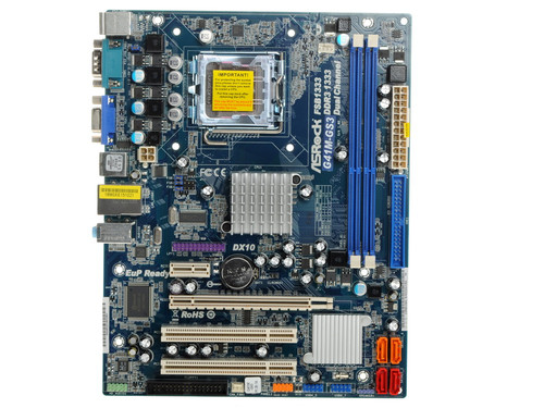
- Плата ASRock LGA775 G41M-GS3 G41/ICH7 2xDDR3-1333 PCI-E DSub 6ch 4xSATA IDE COM GLAN mATX
- Инструкции и файлы
Плата ASRock LGA775 G41M-GS3 G41/ICH7 2xDDR3-1333 PCI-E DSub 6ch 4xSATA IDE COM GLAN mATX

2
Код товара: 0143829
Плата ASRock LGA775 G41M-GS3 G41/ICH7 2xDDR3-1333 PCI-E DSub 6ch 4xSATA IDE COM GLAN mATX

Характеристики
Отзывы2ОбзорыИнструкции и файлы1
Как выбрать?
Советуют эксперты DNS
Инструкции и файлы для Плата ASRock LGA775 G41M-GS3 G41/ICH7 2xDDR3-1333 PCI-E DSub 6ch 4xSATA IDE COM GLAN mATX
Мы рекомендуем скачивать драйверы с официального сайта производителя.Ссылка на ОФ сайт. Материнская плата ASRock G41M-GS3 G41/ICH7
Нашли ошибку?
Выделите текст с ошибкой и нажмите Ctrl+Enter или
напишите нам
.
Указанное предложение действительно на 29.11.2023
-
Страница 1
1 1 1 1 1 G41M-GS User Ma nual V ersion 1.0 Published July 2009 Copyright©2009 ASRock INC. All rights reserved.[…]
-
Страница 2
2 2 2 2 2 Copyright Notice: Copyright Notice: Copyright Notice: Copyright Notice: Copyright Notice: No part of this manual may be reproduced, transcribed, transmitted, or translated in any language, in any form or by any means, except duplication of documentation by the purcha ser for ba ckup purpose, without written consent of ASRock Inc. Products[…]
-
Страница 3
3 3 3 3 3 Contents Contents Contents Contents Contents 1 Introduction 1 Introduction 1 Introduction 1 Introduction 1 Introduction …………………………………………… …………………………………………… …………………………………………… …………………………………………… …………[…]
-
Страница 4
4 4 4 4 4 4 Software Support 4 Software Support 4 Software Support 4 Software Support 4 Software Support ……………………………………. ……………………………………. ……………………………………. ……………………………………. ……………………………………. 50 50 50 50 50 4.1 Instal[…]
-
Страница 5
5 5 5 5 5 Chapter 1 Introduction Chapter 1 Introduction Chapter 1 Introduction Chapter 1 Introduction Chapter 1 Introduction Tha nk you for purcha sing ASRock G41M-GS motherboard, a relia ble motherboard produced under ASRock’s consistently stringent quality control. It delivers excellent performa nce with robust design conforming to ASRock’s c[…]
-
Страница 6
6 6 6 6 6 1.2 1.2 1.2 1.2 1.2 Specifications Specifications Specifications Specifications Specifications Platform — Micro A TX Form Fa ctor: 9.6-in x 7.6-in, 24.4 cm x 19.3 cm CPU — LGA 775 for Intel ® Core TM 2 Extreme / Core TM 2 Quad / Core TM 2 Duo / Pentium ® Dual Core / Celeron ® Dual Core / Celeron ® , supporting Penryn Quad Core Y orkfi[…]
-
Страница 7
7 7 7 7 7 Connector — 4 x SA T AII 3.0 Gb/s connectors (No Support f or RAID and “Hot Plug” functions) (see CAUTION 8 ) — 1 x A T A100 IDE connector (supports 2 x IDE devices) — 1 x Floppy connector — 1 x Print port header — CPU/Cha ssis F AN connector — 24 pin A TX power connector — 4 pin 12V power connector — Front panel audio connector — 2 x[…]
-
Страница 8
8 8 8 8 8 CAUTION! 1. This motherboard supports native FSB1333/1066/800 MHz. For normal operation, you do not need to adjust the jumper settings. For speci al overclocking mode, plea se refer to page 19 for proper jumper settings. 2. About the setting of “Hyper Threa ding T echnology”, plea se check page 31. 3. This motherboard supports U ntied[…]
-
Страница 9
9 9 9 9 9 1 1. Featuring a n adva nced proprietary hardware and software de sign, Intelligent Energy Saver is a revolutionary technology that delivers unparalleled power savings. In other words, it is able to provide excep- tional power saving a nd i mprove power efficiency without sa crificing computing performa nce. Please visit our website f or […]
-
Страница 10
10 10 10 10 10 1.3 Motherboard Layout 1.3 Motherboard Layout 1.3 Motherboard Layout 1.3 Motherboard Layout 1.3 Motherboard Layout 1 PS2_USB_PWR1 IDE1 CHA_FAN1 SPEAKER1 1 HD_AUDIO1 Intel G41 Chipset CLRCMOS1 PANEL1 HDLED RESET PLED PWRBTN 1 CMOS Battery 8Mb BIOS 1 AUDIO CODEC 19.3cm (7.6 in) 24.4cm (9.6 in) ATX12V1 Super IO FLOPPY1 1 2 4 5 7 6 8 9 1[…]
-
Страница 11
11 11 11 11 11 1.4 I/O P 1.4 I/O P 1.4 I/O P 1.4 I/O P 1.4 I/O P anel anel anel anel anel 1 PS/2 Mouse Port (Green) 6 Microphone (Pink) 2 USB 2.0 Ports (USB23) 7 USB 2.0 Ports (USB01) * 3 RJ-45 Port 8 V G A Port 4 Line In (Light Blue) 9 COM Port 5 Line Out (Lime) 1 0 PS/2 Keyboard Port (Purple) * T o enable Multi-Stre a ming function, you need to c[…]
-
Страница 12
12 12 12 12 12 Chapter 2 Installation Chapter 2 Installation Chapter 2 Installation Chapter 2 Installation Chapter 2 Installation G41M-GS is a Micro A TX form fa ctor (9.6″ x 7.6″, 24.4 x 19.3 cm) motherboard. Before you install the motherboard, study the configuration of your cha ssis to ensure that the motherboard fits into it. Make sur[…]
-
Страница 13
13 13 13 13 13 Lift Lever Up to 90° CPU Marked Corner Socket Marked Corner 2.3 CPU Installation 2.3 CPU Installation 2.3 CPU Installation 2.3 CPU Installation 2.3 CPU Installation For the installation of Intel 775-LAND CPU, plea se follow the steps below . Before you in sert the 775-LAND CPU into the socket, ple a se check if the CPU surface is un[…]
-
Страница 14
14 14 14 14 14 For proper inserting, ple a se ensure to match the two orientation key notches of the CPU with the two alignment keys of the socket. Step 2-3. Carefully pla ce the CPU into the socket by using a purely vertical motion. Step 2-4. V erify that the CPU is within the socket and properly mated to the orient keys. Step 3. Re move PnP Ca p […]
-
Страница 15
15 15 15 15 15 2.4 2.4 2.4 2.4 2.4 Installation of CPU Fan and Heatsink Installation of CPU Fan and Heatsink Installation of CPU Fan and Heatsink Installation of CPU Fan and Heatsink Installation of CPU Fan and Heatsink This motherboard is equipped with 775-Pin socket that supports Intel 775-LAND CPU. Plea se adopt the type of heatsink a nd cooling[…]
-
Страница 16
16 16 16 16 16 2.5 Installation of Memory Modules (DIMM) 2.5 Installation of Memory Modules (DIMM) 2.5 Installation of Memory Modules (DIMM) 2.5 Installation of Memory Modules (DIMM) 2.5 Installation of Memory Modules (DIMM) G41M-GS motherboard provides two 240-pin DDR2 (Double Data Rate 2) DIMM slots, a nd supports Dual Cha nnel Memory T echnology[…]
-
Страница 17
17 17 17 17 17 2.6 Expansion Slots (PCI and PCI Express Slots) 2.6 Expansion Slots (PCI and PCI Express Slots) 2.6 Expansion Slots (PCI and PCI Express Slots) 2.6 Expansion Slots (PCI and PCI Express Slots) 2.6 Expansion Slots (PCI and PCI Express Slots) There are 2 PCI slots a nd 2 PCI Express slots on this motherboard. PCI slots: PCI slots are us[…]
-
Страница 18
18 18 18 18 18 2.7 Jumpers Setup 2.7 Jumpers Setup 2.7 Jumpers Setup 2.7 Jumpers Setup 2.7 Jumpers Setup The illustration shows how jumpers are setup. When the jumper ca p is pla ced on pins, the jumper is “Short”. If no jumper ca p is pla ced on pins, the jumper is “Open”. The illustration shows a 3-pin jumper whose pin1 an d pin2 are “S[…]
-
Страница 19
19 19 19 19 19 Standard Setting: If you adopt below DRAM / CPU configuration on this motherboard, you need to adjust the jumpers. Ple a se follow the instructions below to set up the jumpers. Otherwise, the CPU and memory module may not work properly on this motherboard. DRAM DDR2 533 DDR2 1066 CPU FSB533 FSB1066 FSB1333 Jumper Settings FSB1: 2-3 F[…]
-
Страница 20
20 20 20 20 20 2.8 Onboard Headers and Connectors 2.8 Onboard Headers and Connectors 2.8 Onboard Headers and Connectors 2.8 Onboard Headers and Connectors 2.8 Onboard Headers and Connectors Onboard headers and connectors are NOT jumpers. Do NOT place jumper ca ps over these hea ders and connectors. Pla cing jumper ca ps over the headers a nd connec[…]
-
Страница 21
21 21 21 21 21 1. High Definition Audio supports Jack Sensing, but the panel wire on the cha ssis must support HDA to function correctly . Plea se follow the instruction in our ma nual a nd cha ssis manual to in stall your system. 2. If you use AC’97 audio pa nel, plea se install it to the front pa nel audio hea der as below: A. Connect Mic_IN (M[…]
-
Страница 22
22 22 22 22 22 +5V DUMMY DUMMY SPEAKER 1 GND PWR B TN# PLED- PLED+ DUMMY RESET# GND HDLED+ HDLED- 1 System Pa nel Header This header a ccommodates (9-pin P ANEL1) several system front panel (see p.10 No. 17) functions. Cha ssis Spea ker Header Plea se connect the cha ssis (4-pin SPEAKER 1) speaker to this header. (see p.10 No. 14) Cha ssis Fa n Con[…]
-
Страница 23
23 23 23 23 23 20-Pin A TX Power Supply Installation A TX 12V Connector Pl ease note that it is necessary (4-pin A TX12V1) to connect a power supply with (see p.10 No. 29) A TX 12V plug to this connector so that it can provides sufficient power. Failing to do so will cause the failure to power up. A TX Power Connector Plea se connect an A TX power […]
-
Страница 24
24 24 24 24 24 2.9 2.9 2.9 2.9 2.9 SA SA SA SA SA T T T T T AII Hard Disk Setup Guide AII Hard Disk Setup Guide AII Hard Disk Setup Guide AII Hard Disk Setup Guide AII Hard Disk Setup Guide Before installing SA T AII hard disk to your computer , plea se carefully read below SA T AII hard disk setup guide. Some default setting of SA T AII hard disks[…]
-
Страница 25
25 25 25 25 25 2.10 2.10 2.10 2.10 2.10 Serial A Serial A Serial A Serial A Serial A T T T T T A (SA A (SA A (SA A (SA A (SA T T T T T A) / Serial A A) / Serial A A) / Serial A A) / Serial A A) / Serial A T T T T T AII (SA AII (SA AII (SA AII (SA AII (SA T T T T T AII) Hard Disks AII) Hard Disks AII) Hard Disks AII) Hard Disks AII) Hard Disks Insta[…]
-
Страница 26
26 26 26 26 26 Chapter 3 BIOS SETUP UTILITY Chapter 3 BIOS SETUP UTILITY Chapter 3 BIOS SETUP UTILITY Chapter 3 BIOS SETUP UTILITY Chapter 3 BIOS SETUP UTILITY 3.1 3.1 3.1 3.1 3.1 Introduction Introduction Introduction Introduction Introduction This section explains how to use the BIOS SETUP UTILITY to configure your system. The BIOS FWH chip on th[…]
-
Страница 27
27 27 27 27 27 3.1.2 3.1.2 3.1.2 3.1.2 3.1.2 Navigation Keys Navigation Keys Navigation Keys Navigation Keys Navigation Keys Plea se check the following table f or the function descri ption of ea ch navigation key. Navigation Key(s) Function Description / Moves cursor left or right to select Screens / Moves cursor up or down to select items + / — T[…]
-
Страница 28
28 28 28 28 28 3.3 3.3 3.3 3.3 3.3 Smart Screen Smart Screen Smart Screen Smart Screen Smart Screen In the Smart screen, you ca n load the BIOS setup a ccording to your requirements. BIOS SETUP UTILITY Main Advanced H/W Monitor Boot Security Exit Smart Settings Exit system setup after saving the changes. F 1 0k e yc a nb eu s e d for this operation[…]
-
Страница 29
29 29 29 29 29 Load Optimized CPU OC Setting This option only a ppears when you adopt E5000 series CPU. Y ou can use this option to load the optiomized CPU overclocking setting. Configuration options: [2.64 GHz], [2.88 GHz], [3.00 GHz], [3.12 GHz] a nd [3.27 GHz]. Plea se note that overclocing may cause da mage to your CPU and motherboard. It shoul[…]
-
Страница 30
30 30 30 30 30 BIOS SETUP UTILITY CPU Configuration Select Screen Select Item +- Change Option F1 General Help F9 Load Defaults F10 Save and Exit ESC Exit v02.54 (C) Copyright 1985-2005, American Megatrends, Inc. Advanced Boot Failure Guard Spread Spectrum [Enabled] [Auto] Select Screen Select Item +- Change Option F1 General Help F9 Load Defaults […]
-
Страница 31
31 31 31 31 31 Intel (R) Virtualization tech. When this option is set to [Enabled], a VMM (V irtual Ma chine Architecture) ca n utilize the additional hardware ca pabilities provided by V anderpool T echnology . This option will be hidden if the installed CPU does not support Intel (R) Virtualization T echnology . CPU Thermal Throttling Y ou may se[…]
-
Страница 32
32 32 32 32 32 3.4.2 3.4.2 3.4.2 3.4.2 3.4.2 Chipset Configuration Chipset Configuration Chipset Configuration Chipset Configuration Chipset Configuration BIOS SETUP UTILITY v02.54 (C) Copyright 1985-2005, American Megatrends, Inc. Chipset Configuration Memory Remap Feature DRAM Frequency Flexibility Option DRAM tCL DRAM tRCD DRAM tRP DRAM tRAS DRA[…]
-
Страница 33
33 33 33 33 33 DRAM tWR This controls the number of DRAM clocks f or TW R. Min: 3. Max: 15. The default value is [Auto]. DRAM tWTR This controls the number of DRAM clocks for TWTR. Min: 2. M ax: 15. The default value is [Auto]. DRAM tRRD This controls the number of DRAM clocks for TRRD. Min: 2. Max: 15. The default value is [Auto]. DRAM tRTP This c[…]
-
Страница 34
34 34 34 34 34 DRAM RCOMP STRENGTH Configuration BIOS SETUP UTILITY DRAM RCOMP STRENGTH Settings Select Screen Select Item +- Change Option F1 General Help F9 Load Defaults F10 Save and Exit ESC Exit v02.54 (C) Copyright 1985-2005, American Megatrends, Inc. Advanced Select Screen Select Item +- Change Option F1 General Help F9 Load Defaults F10 Sav[…]
-
Страница 35
35 35 35 35 35 DRAM CH1 G3 (Control2) This controls the number of DRAM CH1 G3 (Control2). Min: 1. M ax: 15. The default value is [Auto]. DRAM CH1 G4 (Clocks1) This controls the number of DRAM CH1 G4 (Clocks1). Min: 1. Max: 15. The default value is [Auto]. DRAM CH1 G5 (Clocks2) This controls the number of DRAM CH1 G5 (Clocks2). Min: 1. Max: 15. The […]
-
Страница 36
36 36 36 36 36 DRAM DLL SKEW Settings BIOS SETUP UTILITY DRAM DLL SKEW Settings Select Screen Select Item +- Change Option F1 General Help F9 Load Defaults F10 Save and Exit ESC Exit v02.54 (C) Copyright 1985-2005, American Megatrends, Inc. Advanced Select Screen Select Item +- Change Option F1 General Help F9 Load Defaults F10 Save and Exit ESC Ex[…]
-
Страница 37
37 37 37 37 37 DRAM CH1 CMD SKEW This controls the number of DRAM CH1 CMD SKEW . The default value is [Auto]. DRAM CH1 CTRL0 SKEW This controls the number of DRAM CH1 CTRL0 SKEW . The default value is [Auto]. DRAM CH1 CTRL1 SKEW This controls the number of DRAM CH1 CTRL1 SKEW . The default value is [Auto]. DRAM CH1 CTRL2 SKEW This controls the numb[…]
-
Страница 38
38 38 38 38 38 Primary Gra phics Ada pter This allows you to select [Onboard], [PCI] or [PCI Express] a s the boot gra phic ada pter priority . The default value is [PCI]. Share Memory This allows you to set share memory feature. The default value is [Auto]. Configuration options: [Auto], [32MB], [64MB], [128MB] and [256MB]. P A VP Mode Use this op[…]
-
Страница 39
39 39 39 39 39 DRAM V oltage Use this to select DRAM V oltage. Configuration options: [Auto], [1.794V], [1.851V], [1.908V], [1.965V], [2.029V], [2.086V], [2.144V], [2.201V], [2.314], [2.371V], [2.428V], [2.485V], [2.549V], [2.606V], [2.664V] and [2.720V]. The default value of this feature is [Auto]. NB V oltage Use this to select NB V oltage. Confi[…]
-
Страница 40
40 40 40 40 40 BIOS SETUP UTILITY ACPI Configuration Select auto-detect or disable the STR feature. Select Screen Select Item +- Change Option F1 General Help F9 Load Defaults F10 Save and Exit ESC Exit v02.54 (C) Copyright 1985-2005, American Megatrends, Inc. Advanced Suspend T o RAM Repost Video on STR Resume Check Ready Bit Restore on AC/Power L[…]
-
Страница 41
41 41 41 41 41 BIOS SETUP UTILITY IDE Configuration Set [Compatible] when Legacy OS (MS-DOS, Win NT) device is used. Set [Enhanced] when Native OS (Win2000 / XP) is used. v02.54 (C) Copyright 1985-2005, American Megatrends, Inc. Advanced A T A/IDE Configuration [Enhanced] Select Screen Select Item +- Change Option F1 General Help F9 Load Defaults F[…]
-
Страница 42
42 42 42 42 42 TYPE Use this item to configure the type of the IDE device that you specify. Configuration options: [Not In stalled], [Auto], [CD/D V D], a nd [ARMD]. [Not Installed]: Select [Not Installed] to disable the use of IDE device. [Auto]: Select [Auto] to automatically detect the hard disk drive. After selecting the hard disk information i[…]
-
Страница 43
43 43 43 43 43 DMA Mode DMA ca pability allows the improved tra nsfer-speed a nd data-integrity for compatible IDE devices. S.M.A.R.T. Use this item to ena ble or disable the S.M.A.R.T . (Self-Monitoring, Analysis, a nd Reporting T echnology) feature. Configuration options: [Disabled], [Auto], [Enabled]. 32-Bit Data T ra nsfer Use this item to ena […]
-
Страница 44
44 44 44 44 44 3.4.6 3.4.6 3.4.6 3.4.6 3.4.6 Floppy Configuration Floppy Configuration Floppy Configuration Floppy Configuration Floppy Configuration In this section, you may configure the type of your floppy drive. 3.4.7 3.4.7 3.4.7 3.4.7 3.4.7 Super IO Configuration Super IO Configuration Super IO Configuration Super IO Configuration Super IO Con[…]
-
Страница 45
45 45 45 45 45 BIOS SETUP UTILITY USB Configuration T o enable or disable the onboard USB controllers. Select Screen Select Item +- Change Option F1 General Help F9 Load Defaults F10 Save and Exit ESC Exit v02.54 (C) Copyright 1985-2005, American Megatrends, Inc. Advanced USB Controller USB 2.0 Support Legacy USB Support [Enabled] [Enabled] [Enable[…]
-
Страница 46
46 46 46 46 46 3.5 3.5 3.5 3.5 3.5 Hardware Health Event Monitoring Screen Hardware Health Event Monitoring Screen Hardware Health Event Monitoring Screen Hardware Health Event Monitoring Screen Hardware Health Event Monitoring Screen In this section, it allows you to monitor the status of the hardware on your system, including the para meters of t[…]
-
Страница 47
47 47 47 47 47 3.6 3.6 3.6 3.6 3.6 Boot Screen Boot Screen Boot Screen Boot Screen Boot Screen In this section, it will display the available devices on your system for you to config- ure the boot settings and the boot priority. 3.6.1 3.6.1 3.6.1 3.6.1 3.6.1 Boot Settings Configuration Boot Settings Configuration Boot Settings Configuration Boot Se[…]
-
Страница 48
48 48 48 48 48 3.7 3.7 3.7 3.7 3.7 Security Screen Security Screen Security Screen Security Screen Security Screen In this section, you may set or cha nge the supervisor/user pa ssword for the syste m. For the user pa ssword, you may also clear it. BIOS SETUP UTILITY Main Smart Advanced H/W Monitor Boot Exit Install or Change the password. Select S[…]
-
Страница 49
49 49 49 49 49 BIOS SETUP UTILITY Main Smart Advanced H/W Monitor Boot Security Exit system setup after saving the changes. F10 key can be used for this operation. Select Screen Select Item Enter Go to Sub Screen F1 General Help F10 Save and Exit ESC Exit F9 Load Defaults v02.54 (C) Copyright 1985-2005, American Megatrends, Inc. Exit Save Changes a[…]
-
Страница 50
50 50 50 50 50 Chapter 4 Sof Chapter 4 Sof Chapter 4 Sof Chapter 4 Sof Chapter 4 Sof tware Suppor tware Suppor tware Suppor tware Suppor tware Suppor t t t t t 4.1 4.1 4.1 4.1 4.1 Install Operating System Install Operating System Install Operating System Install Operating System Install Operating System This motherboard supports various Microsoft ?[…]