
Скачать
Руководство
пользователя
www.xerox.com/support
WorkCentre 5016, 5020/B, 5020/DB
XE3025RU0-1
Просмотр
Доступно к просмотру 99 страниц. Рекомендуем вам скачать файл инструкции, поскольку онлайн просмотр документа может сильно отличаться от оригинала.
-
WorkCentre 5020/DN
Руководство
пользователя
XE3026RU0-1
www.xerox.com/support
-
Переведено:
Xerox
GKLS European Operations
Bessemer Road
Welwyn Garden City
Hertfordshire
AL7 1BU
UK
© Fuji Xerox Co., Ltd., 2008 г. Все права защищены.
Защита авторских прав распространяется на все формы и виды материалов и
информации, которые подлежат таковой защите в соответствии с действующими
правовыми и законодательными нормами, включая, без каких-либо ограничений,
материалы, являющиеся продуктами программного обеспечения и отображаемые на
экране, например, пиктограммы, экранные страницы, графические изображения и т.п.
®
Xerox  и все упоминаемые в данном документе названия и номера изделий Xerox
являются товарными знаками Xerox Corporation. Настоящим признаются товарные знаки
других компаний, упоминаемые в данном документе.
Приведенная здесь информация верна на момент опубликования. Xerox оставляет за
собой право изменять ее в любое время без предварительного уведомления. В
последующие издания этого документа будут вноситься изменения и технические
уточнения. Самая последняя информация содержится на сайте www.xerox.com.
Типовые нормативные требования по экспорту изделия
Экспорт этого оборудования осуществляется в строгом соответствии с законами Японии,
регламентирующими внешнеторговую деятельность и операции с иностранной валютой,
и/или нормативными документами США в отношении контроля за экспортом. Если вы
хотите экспортировать это оборудование, вам необходимо получить соответствующую
лицензию на экспорт у правительства Японии или его посреднической организации и/или
разрешение на реэкспорт у правительства США или его посреднической организации.
Дополнительные нормативные требования по экспорту изделия
Экспорт этого оборудования осуществляется в строгом соответствии с законами Японии,
регламентирующими внешнеторговую деятельность и операции с иностранной валютой,
и/или нормативными документами США в отношении контроля за экспортом. Если вам
известно, что данное оборудование применялось или применяется при разработке,
производстве или использовании любого оружия массового уничтожения, включая
ядерное, химическое и биологическое, вам необходимо получить договор купли-
продажи, законный контракт или другую соответствующую информацию от импортера и
соответствующую лицензию на экспорт от правительства Японии или его
посреднической организации и/или разрешение на реэкспорт от правительства США или
его посреднической организации.
-
Содержание
1   Перед началом использования аппарата........................................7
Горячая линия Xerox ..............................................................................7
Серийный номер ................................................................................7
Условные обозначения ..........................................................................8
Информационные ресурсы....................................................................9
Правила техники безопасности.............................................................9
ПРЕДУПРЕЖДЕНИЕ - Информация об электробезопасности ....10
Сведения о мерах безопасности при работе с лазером ..............11
Техника безопасности при эксплуатации ......................................11
Сведения по обслуживанию ...........................................................12
Сведения о выделении озона.........................................................12
Сведения по расходным материалам............................................13
Радиочастотное излучение.............................................................13
Аттестация безопасности аппарата ...............................................13
Нормативная информация ..................................................................14
Знак CE.............................................................................................14
Соответствие экологическим нормам.................................................15
США ..................................................................................................15
Незаконное копирование .....................................................................15
Утилизация батарей и повторное использование аккумуляторов ...16
Переработка и утилизация аппарата..................................................16
Все страны. Северная Америка - США и Канада..........................16
Европейский Союз ...........................................................................16
2   Обзор аппарата...................................................................................18
Компоненты аппарата ..........................................................................18
Вид спереди .....................................................................................18
Вид внутри........................................................................................20
Вид сзади..........................................................................................21
Функции устройства..............................................................................22
Печать...............................................................................................22
Копирование.....................................................................................22
Сканирование...................................................................................22
Панель управления ..............................................................................23
Дисплей ............................................................................................23
Кнопка/индикаторы <Переключатель дисплея>............................23
Кнопка <Копирование>....................................................................23
Кнопка <Сканирование>..................................................................24
Индикатор <обмена данными с компьютером> ............................24
Цифровая клавиатура .....................................................................24
3
- 1
- 2
- 3
- 4
- 99
Страницы и текст этой инструкции
 Xerox WorkCentre 5020(DN). Страница №1") Руководство пользователя МФУ (многофункционального устройства) Xerox WorkCentre 5020(DN)
Руководство пользователя МФУ (многофункционального устройства) Xerox WorkCentre 5020(DN)
 Xerox WorkCentre 5020(DN). Страница №2") Информация отображена на картинке
Информация отображена на картинке
 Xerox WorkCentre 5020(DN). Страница №3") Информация отображена на картинке
Информация отображена на картинке
 Xerox WorkCentre 5020(DN). Страница №4") Информация отображена на картинке
Информация отображена на картинке
 Xerox WorkCentre 5020(DN). Страница №5") Информация отображена на картинке
Информация отображена на картинке
Как использовать наш сайт инструкций OnlineManuals.ru
Наша цель состоит в том, чтобы предоставить вам быстрый доступ к содержанию инструкции для МФУ (многофункционального устройства) Xerox WorkCentre 5020(DN).
С помощью онлайн просмотра, Вы можете быстро просмотреть содержимое инструкции и найти решение проблемы с МФУ (многофункционального устройства) Xerox WorkCentre 5020(DN).
Для Вашего удобства
Если листать руководство пользователя МФУ (многофункционального устройства) Xerox WorkCentre 5020(DN) прямо на сайте, не очень удобно для Вас, есть два возможных решения:
• Просмотр в полноэкранном режиме — легко просмотреть руководство пользователя (без загрузки его на свой компьютер), Вы можете использовать режим полноэкранного просмотра.
Для просмотра инструкции пользователя МФУ (многофункционального устройства) Xerox WorkCentre 5020(DN) на полном экране, используйте кнопку «Открыть в Pdf-viewer».
• Загрузка на компьютер — Вы можете также скачать Руководство пользователя МФУ (многофункционального устройства) Xerox WorkCentre 5020(DN) на свой компьютер и сохранить его в файлах.
Многие люди предпочитают читать документы не на экране, а в печатной версии.
Возможность печати руководства пользователя также была предусмотрена на нашем сайте,
и вы можете использовать ее, нажав на иконку «печать» в Pdf-viewer.
Нет необходимости печатать все руководство МФУ (многофункционального устройства) Xerox WorkCentre 5020(DN), можно выбрать только нужные страницы инструкции.
![]()
Work Center 5016, 5020
Service Documentation
701P48365 June 2008
CAUTION
Certain components in the Work Center 5016/ 5020 are susceptible to damage from electrostatic discharge. Observe all ESD procedures to avoid component damage.
While Xerox has tried to make this documentation accurate, Xerox will have no liability arising out of any inaccuracies or ommissions. Changes are periodically made to this document. Changes, technical inaccuracies, and typographical errors will be corrected in subsequent editions.
All service documentation is supplied to Xerox external customers for informational purposes only. Xerox service documentation is intended for use by certified product trained service personal only. Xerox does not warrant or represent that such documentation is complete, nor does Xerox represent or warrant that it will notify or provide to such customer any future changes to this documentation. Customer performed service of equipment, or modules, components or parts of such equipment may affect the warranty offered by Xerox with respect to such equipment. You should consult the applicable warranty for its terms regarding customer or third party provided service. If the customer services such equipment, modules, components or parts thereof, the customer releases Xerox from any and all liability for the customer actions, and the customer agrees to indemnify, defend and hold Xerox harmless from any third party claims which arise directly or indirectly from such service.
Acknowledgements
Prepared by Global Knowledge & Llanguage Services — North America 800 Phillips Road — Building 0218-01A
Webster, New York 14580-9791
ISO9001 AND ISO27001 Certified
© Copyright 2007-2008 by Xerox Corporation. All rights reserved. Xerox® and all product names and number names
are trademarks of Xerox Corporation. Printed in the USA

WorkCentre 5016, 5020
Service Documentation
WorkCentre 5016, 5020 Service Documentation
701P48365
Reissue
June, 2008
***Xerox Private Data***
All service documentation is supplied to Xerox external customers for informational purposes only. Xerox service documentation is intended for use by certified, product-trained service personnel only. Xerox does not warrant or represent that it will notify or provide to such customer any future change to this documentation. Customer performed service of equipment, or modules, components, or parts of such equipment may affect whether Xerox is responsible to fix machine defects under the warranty offered by Xerox with respect to such equipment. You should consult the applicable warranty for its terms regarding customer or third-party provided service.
If the customer services such equipment, modules, components or parts thereof, the customer releases Xerox from any and all liability for the customer actions, and the customer agrees to indemnify, defend and hold xerox harmless from any third party claims which arise directly or indirectly for such service.
While Xerox has tried to make the documentation accurate, Xerox will have no liability arising out of any inaccuracies or omissions. Changes are periodically made to this document. Changes, technical inaccuracies, and typographical errors will be corrected in subsequent editions.
Prepared by:
Xerox Corporation
Global Knowledge and Language Services
800 Phillips Road, Bldg. 0218-01A
Webster, New York 14580-9791
USA
©2007 — 2008 by Xerox Corporation. All rights reserved.
Copyright protection claimed includes all forms and matters of copyrightable material and information now allowed by statutory judicial law or hereinafter granted, including without limitation, material generated from the software programs which are displayed on the screen such as icons, screen displays, looks, etc.
Printed in the United States of America.
XEROX® and all Xerox product names mentioned in this publication are trademarks of XEROX CORPORATION. Other company trademarks are also acknowledged.
PANTONE is a registered trademark of Pantone, Inc.
Changes are periodically made to this document. Changes, technical inaccuracies, and typographic errors will be corrected in subsequent editions.
CAUTION
This equipment generates, uses and can radiate radio frequency energy, and if not installed and used in accordance with the instructions documentation, may cause interference to radio communications. It has been tested and found to comply with the limits for a Class A computing device pursuant to subpart B of part 15 of FCC rules, which are designed to provide reasonable protection against such interference when operated in a commercial environment. Operation of this equipment in a residential area is likely to cause interference in which case the user, at his own expense, will be required to correct the interference.
|
Front Matter |
June, 2008 |
Reissue |
|
i |
WorkCentre 5016, 5020 |

|
Front Matter |
June, 2008 |
Reissue |

Introduction
|
How To Use This Manual…………………………………………………………………………………… |
iii |
|
Reissue |
June, 2008 |
Introduction |
|
WorkCentre 5016, 5020 |
i |

|
Introduction |
June, 2008 |
Reissue |

How To Use This Manual
This manual is used as the standard service manual for the WorkCentre 5016, 5020.
Enter any comments and/or corrections regarding the WorkCentre 5016, 5020 Service Documentationl on the Publication Comment Sheet, and send it to the Technical Support Center SDEG.
This manual describes the standard procedures for servicing the WorkCentre 5016, 5020. Refer to Section 1 Service Call Procedure for efficient and effective servicing during maintenance calls.
Chain 1 Standby Power
Chain 2 Mode Selection
Chain 3 Machine Run Control
Chain 4 Start Print Power
Chain 6 Imaging
Chain 7 Paper Supplying
Chain 8 Paper Transportation
Chain 9 Marking
Chain 10 Fusing and Copy Transportation
Contents of Manual
This manual is divided into nine sections as described below.
Section 1 Service Call Procedures
This section describes the structured process for determining the type and sequence of actions that are performed during a service call.
Section 2 Status Indicator RAPs
This section contains the Repair Analysis Procedures (RAPs) necessary to repair all faults other than image quality faults.
Section 3 Image Quality RAPs
This section contains the Repair Analysis Procedures (RAPs) that are used to diagnose image quality defect problems.
Section 4 Removal/Replacement and Adjustment Procedures
This section contains the removal, replacement, and adjustment procedures for components of WorkCentre 5016, 5020.
Section 5 Parts List
This section contains a list of spare parts list for the WorkCentre 5016, 5020.
Section 6 General Procedures/Information
This section contains frequently used procedures that relate to the diagnosis, setup, or operation of the machine. It also contains pertinent information that will not be found in any other part of the service documentation.
Section 7 Wiring Data
This section contains the wiring information for the WorkCentre 5016, 5020. It contains a connector list/locator, wirenet diagrams, and Block Schematic Diagrams (BSDs) for the following chains:
Description of Terminology and Symbols
The terminology and symbols used throughout this service manual are described as follows:
WARNING
A Warning statement indicates an operating or maintenance procedure, practice, or condition that, if not strictly observed, could result in personal injury or loss of life.
CAUTION
A Caution statement indicates an operating or maintenance procedure, practice, or condition that, if not strictly observed, could result in damage to, or destruction of, equipment.
NOTE: A Note statement indicates an operating or maintenance procedure, practice, or condition that is necessary to accomplish a task efficiently.
Reference:
Used when other explanations are given.
Purpose:
Used to describe the purposes of adjustment and troubleshooting.
REP:
Indicates the removal/replacement procedure for reference.
ADJ:
Indicates the adjustment procedure for reference.
PL:
Indicates the parts list for reference.
ASSY:
Means Assembly.
Safety Critical Components (SCC):
These are components, such as electrostatic-sensitive IC chips, which could be damaged if not handled properly. Follow the regulations regarding Safety Critical Components set by XEROX Corp.
|
Reissue |
June, 2008 |
Introduction |
|
WorkCentre 5016, 5020 |
iii |

|
Introduction |
June, 2008 |
Reissue |

1 Service Call Procedures
|
1.1 |
Before Starting Service ………………………………………………………………………………… |
1-3 |
|
1.2 |
Service Call Procedure ………………………………………………………………………………… |
1-4 |
|
1.3 |
Service Call Details ……………………………………………………………………………………… |
1-4 |
|
1.4 |
TRIM Checklist……………………………………………………………………………………………. |
1-5 |
|
1.5 |
Periodic Replacement Parts/Consumables List ……………………………………………….. |
1-5 |
|
Reissue |
June, 2008 |
Service Call Procedures |
|
WorkCentre 5016, 5020 |
1-1 |

|
Service Call Procedures |
June, 2008 |
Reissue |
|
1-2 |
WorkCentre 5016, 5020 |
![]()
1.1 Before Starting Service
1.1.1Safety
To prevent any accident that may occur during maintenance service, any warning or any caution regarding the service must be strictly observed. Do not perform any hazardous operation.
1.Power Supply
To prevent electrical shocks, burns, or injury, etc., be sure to switch OFF the machine and disconnect the plug before starting the maintenance service. If the machine has to be switched ON, such as when measuring a voltage, take extra care to avoid an electrical shock.
2.Drive Area
Never inspect, clear or lubricate the drive components, such as chain belts, chain wheels or gears, when the machine is in operation.
3.Heavy Parts
When removing or installing heavy parts, keep your back straight and lift with your legs. Some parts should not be lifted by one person:
IOT (Platen): 31.5kg (requires 3 persons)
2 Tray Modules: 8.6kg (requires 2 persons)
Take extra care of your working posture to prevent backache.
4.Safety Devices
See that safety devices for preventing accidents, such as fuses, circuit breakers, interlock switches, etc., and those for protecting customers from injury, such as panels and covers, function properly. Modifications that hinder the function of any safety devices are strictly prohibited.
5.Installing and Removing Parts
The edges of parts and covers may be sharp, so take care not to touch them. Be careful not to touch those parts, and wipe off any oil that may have adhered to your fingers or hands before servicing. When pulling out parts, cables, etc., do it gently. Do not use excessive force.
6.Specified Tools
Follow the instructions when a particular tool is specified.
7.Cleaning Up Toner Spills
Since toner can be explosive, sweep or brush any spilled toner into a container to collect it. To clean away the remaining toner using a vacuum cleaner, always use an FX standard vacuum cleaner that is toner-tolerant. Never use the customer’s vacuum cleaner.
8.Earthquake Preparedness Measures
If the customer requests earthquake proofing, an earthquake preparedness kit is available.
Check the Service Guide for more information on the earthquake preparedness kit.
9.Modifications to the Machine
Before altering the machine, submit an irregular use license application.
10.Other Safety Precautions
Follow the recommendations in WORKING PRACTICES FOR ENGINEERS issued by FXAP EH&S (Environmental Health and Safety).
1.1.2Things to Note When Handling Customer Data
1.Handling of copied/printed customer data.
Before you bring back any sample for the purpose of investigation/analysis, always obtain permission from the customer. Make sure you assure them that the data will not be used for any other purpose.
2.Security-related NVM values that were changed during diagnostics.
If any security-related NVM values, such as polling, were set for test purposes, make sure you restore them to their original values after the test.
3.Other things to note when handling customer data.
Follow the safety guidelines established within the OpCo and ensure that customer data do not get compromised during service.
1.1.3 Other Precautions
To avoid performing wrong or unnecessary service, observe the following:
1.Reference Materials
Read all relevant service documentation, so that you can take a systematic approach.
2.Disassembling
Make sure to note the assembled condition of the machine before removing parts or disassembling it.
3.Installation and Adjustment
After the installation or adjustment is complete, check that no parts or tools are left inside the machine.
4.Handling of replaced parts and consumables
Make sure that any replaced parts or consumables, as well as the packaging materials, are taken back to the Service Center.
WARNING
Never discard the Drum/Toner Cartridges into a fire. Always keep them away from open flames to prevent them from igniting and causing a fire.
NOTE: For separation and processing methods for replaced parts or consumables, refer to Common Technical Information No. 2-138 for all machines.
•If you have replaced the following consumables, affix the «U-TAG» so that the recyclable parts will be handled appropriately.
a.Drum Cartridge
b.Toner Cartridge
•For recyclable parts, fill in the necessary items on the «U-TAG.»
5.General Precautions
•Take care not to disturb the customer’s daily work.
•Place any service-related trash into a trash bag and bring it to the service office.
•Clearly record the following information in the Machine Service Log:
– Details of the service call
– Parts and consumables replaced
|
Reissue |
June, 2008 |
Service Call Procedures |
|
1.1 |
||
|
WorkCentre 5016, 5020 |
1-3 |

1.2 Service Call Procedure
1.2.1 Initial Actions
1.Ask the operator(s) about the machine’s condition.
2.Record the billing meter readings.
3.Inspect any faulty copies, then check the machine.
4.Check the Service Log.
1.2.2 Actions to Take During UM (Unscheduled Maintenance)
1.Perform the service flow in Section 2 Status Indicator RAPs.
2.Perform the applicable RAP in Section 2 Status Indicator RAPs.
If there are no applicable RAPs, troubleshoot by referring to the BSD in Section 7 Wiring Data.
3.Check the copy quality.
Make several copies using the Test Pattern (499T247), then check the quality.
4.Look at the last 20 error codes in order to understand the machine status.
•Enter Diagnostic Mode. Enter [40-01] (Display Error History How to Enter the Diagnostic Mode).
•When the last error code is displayed, press the [Start] key to return to the Function input screen.
•Pressing the [Stop] key during the display will stop it and return you to the Function input screen.
5.Repair all the secondary problems.
6.Perform TRIM servicing.
1.2.3 Actions to Take During SM (Scheduled Maintenance)
1.Check the copy quality.
Make several copies using the Test Pattern (499T247), then check the quality.
2.Look at the last 20 error codes in order to understand the machine status.
•Enter Diagnostic Mode. Enter [40-01] (Display Error History How to Enter the Diagnostic Mode).
•When the last error code is displayed, press the [Start] key to return to the Function input screen.
•Pressing the [Stop] key during the display will stop it and return you to the Function input screen.
3.Perform TRIM servicing.
1.2.4 Final Actions
1.Check overall machine operation/features.
2.Check the machine exterior and consumables.
3.Train the operator as required.
4.Complete the Service Log and Service Report.
5.Keep the copy samples with the Service Log.
1.3 Service Call Details
1.3.1 Initial Actions
1.Ask the operator(s) about the machine’s condition.
•Frequency and location of recent paper jams
•Copy quality
2.Record the billing meter readings.
3.Inspect any faulty copies, then check the machine.
4.Check the copy sample and the Service Log from the last call.
1.3.2 Checking Reproducibility of Problem
1.Perform the service flow in Section 2 Status Indicator RAPs.
2.Perform the applicable RAP in Section 2 Status Indicator RAPs.
3.If there are no applicable RAPs, troubleshoot by referring to the BSD in Section 7 Wiring Data.
1.3.3 Checking Copy Quality
1.Make several copies using the Test Pattern (499T247), then check the quality.
2.If there is a problem in copy quality, perform the applicable RAP in Section 3 Image Quality.
1.3.4 TRIM Servicing
Perform TRIM servicing during the maintenance call.
1.Perform the necessary TRIM items using the TRIM Checklist.
2.Check for parts that require periodic cleaning/replacement by referring to the TRIM Checklist and the Periodic Replacement Parts/Consumables List. Clean them if necessary. If replaced, always clear the counters of the corresponding items in the Chain Function.
|
Service Call Procedures |
June, 2008 |
Reissue |
|
1.2, 1.3 |
||
|
1-4 |
WorkCentre 5016, 5020 |

1.4 TRIM Checklist
A:Check. Clean, replace, or replenish if necessary.
B:Always check and clean.
*: Always replace at the specified interval.
|
Table 1 |
||||
|
Every |
||||
|
No. |
Service Items |
time |
Service Details |
|
|
1.1 |
Check before servicing |
A |
Turn on the machine, and make sure that there are |
|
|
(check machine operation) |
no abnormal sounds. |
|||
|
1.2 |
Check before Servicing |
A |
Make several copies using the Test Pattern |
|
|
(copy the Test Pattern) |
(499T247), then check the image quality. |
|||
|
2 |
Clean the interior of the |
A |
Clean the paper dust and toner residue in the paper |
|
|
machine (paper transport |
path and on the jam sensor. |
|||
|
system) |
||||
|
3 |
Clean the IIT |
A |
• |
Clean the Platen Glass surface and the Platen |
|
Cushion with the optical cleaning cloth. |
||||
|
• |
Clean the Reflector, back of the Platen Glass, |
|||
|
mirrors and lens with the optical cleaning cloth. |
||||
|
5 |
Safety Precautions |
B |
• |
Make sure that the power cord is plugged in |
|
properly. |
||||
|
• |
Make sure that there are no cracks in the |
|||
|
power plug and no holes or cuts in the power |
||||
|
cord insulation. |
||||
|
• |
If an extension cord or power strip is used, |
|||
|
make sure it is of sufficient capacity to handle |
||||
|
the power requirements of the machine. |
||||
|
• |
Make sure that no more than one power plug |
|||
|
is connected to a single socket. |
||||
|
6.1 |
Check after servicing |
A |
Make several copies using the Test Pattern |
|
|
(copy quality check) |
(499T247), then check the image quality. |
|||
|
6.2 |
Check after servicing |
A |
• |
Check the paper feed. |
|
(check machine operation) |
• |
Make sure that there are no abnormal sounds. |
||
|
6.3 |
Check after servicing |
A |
Create the Service Log and Service Report. |
|
|
(check the meter) |
||||
CAUTION
Do not touch the Drum of the Drum Cartridge.
1.5 Periodic Replacement Parts/Consumables List
When servicing the machine, check the number of copies and the replacement interval for the consumables and parts that require periodical cleaning/replacement. Clean or replace them if necessary. The IOT history can be checked at Chain-Function > NVRAM R/W, while the IIT history can be checked in the Counters (refer to Diagnostic Mode in Section 2 Status Indicator RAPs). For items that cannot be checked in the Diagnostic Mode, clean or replace them according to the replacement intervals (standard PV).
CAUTION
Do not keep toner and drum cartridges in your car for long periods of time.
Table 1
|
Parts/Consumables |
Replacement |
||
|
No |
Name/PL No. |
Interval (copies) |
Counters Check |
|
1 |
Tray 1 Feed Roll/ |
50,000 |
[29/34] [29/24] [29/14] [29/4] |
|
Retard Pad |
Count up 1 for every feed. Replace both at the |
||
|
same time. |
|||
|
2 |
Tray 2 Feed Roll/ |
100,000 |
[29/25] [29/15] [29/5] |
|
Retard Roll |
Count up 1 for every feed. Replace both at the |
||
|
same time. |
|||
|
3 |
MSI Feed Roll/ |
50,000 |
[29/39] [29/29] [29/19] [29/9] |
|
Retard Pad |
Count up 1 for every feed. Replace both at the |
||
|
same time. |
|||
|
4 |
Fuser Unit |
100,000 |
[21/39] [21/29] [21/19] [21/9] |
|
Count up 1 for every feed. |
|||
|
5 |
Toner Cartridge |
6,000 |
|
|
6 |
Drum Cartridge |
36,000 |
31,000 (Warning) |
|
36,000 (Machine Stops) |
|||
|
Reissue |
June, 2008 |
Service Call Procedures |
|
1.4, 1.5 |
||
|
WorkCentre 5016, 5020 |
1-5 |

|
Service Call Procedures |
June, 2008 |
Reissue |
|
1.4, 1.5 |
||
|
1-6 |
WorkCentre 5016, 5020 |

2 Status Indicator RAPS
Error Codes
|
Fault Repair Overview and List of Error Codes……………………………………………………… |
2-3 |
RAPs
|
U0-1 Main Motor Stop Error ……………………………………………………………………………….. |
2-25 |
|
U1-1 Main Motor Rotation Error ………………………………………………………………………….. |
2-25 |
|
U2-1 Carriage Module Fail …………………………………………………………………………………. |
2-26 |
|
U3-5 Laser Power Or ROS Motor Fail ………………………………………………………………… |
2-26 |
|
U4-1 Fuser On Time Fail…………………………………………………………………………………… |
2-27 |
|
U4-2 Over Heat Temp Fail ………………………………………………………………………………… |
2-27 |
|
U4-3 FS1 Thermistor Defect ……………………………………………………………………………… |
2-28 |
|
U4-9 Fuser Fan Defect……………………………………………………………………………………… |
2-28 |
|
U6-2 RAM Read/Write Check Error ……………………………………………………………………. |
2-29 |
|
U6-3 NVM Data Defect …………………………………………………………………………………….. |
2-29 |
|
U6-4 NVM Read/Write Cannot Be Executed ……………………………………………………….. |
2-30 |
|
U6-5 CPU Power To Access NVM Is Not Enough ………………………………………………… |
2-30 |
|
U7-0 UI Communication TimeOut ………………………………………………………………………. |
2-31 |
|
U7-1 UI Communication Error……………………………………………………………………………. |
2-31 |
|
U8-1 Billing Counter Defect……………………………………………………………………………….. |
2-32 |
|
U9-0 HVPS Fail……………………………………………………………………………………………….. |
2-32 |
|
062-300 Platen Interlock Open …………………………………………………………………………… |
2-33 |
|
062-345 IISS EEPROM Failure…………………………………………………………………………… |
2-33 |
|
062-360 Carriage Position Fail……………………………………………………………………………. |
2-34 |
|
062-371 Lamp Illumination Fail …………………………………………………………………………… |
2-34 |
|
062-380 AGC Failure ………………………………………………………………………………………… |
2-35 |
|
062-386 AOC Failure ………………………………………………………………………………………… |
2-35 |
|
062-392 IPS PWB Memory Fail ………………………………………………………………………….. |
2-36 |
|
062-393 IPS PWB Fail ………………………………………………………………………………………. |
2-36 |
|
005-170 DADF Feed Failure ………………………………………………………………………………. |
2-37 |
|
005-171 DADF Regi / Exit Failure………………………………………………………………………. |
2-38 |
|
005-172 DADF Inverted Document Jam ………………………………………………………………. |
2-39 |
|
005-198 Short Scan Jam …………………………………………………………………………………… |
2-40 |
|
005-199 Long Scan Jam ……………………………………………………………………………………. |
2-40 |
|
005-305 Feeder Top Cover Open ……………………………………………………………………….. |
2-41 |
|
005-920 Static Jam …………………………………………………………………………………………… |
2-41 |
|
Reissue |
June, 2008 |
Status Indicator RAPS |
|
WorkCentre 5016, 5020 |
2-1 |

|
Status Indicator RAPS |
June, 2008 |
Reissue |
|
2-2 |
WorkCentre 5016, 5020 |
Fault Repair Overview and List of Error Codes |
. |
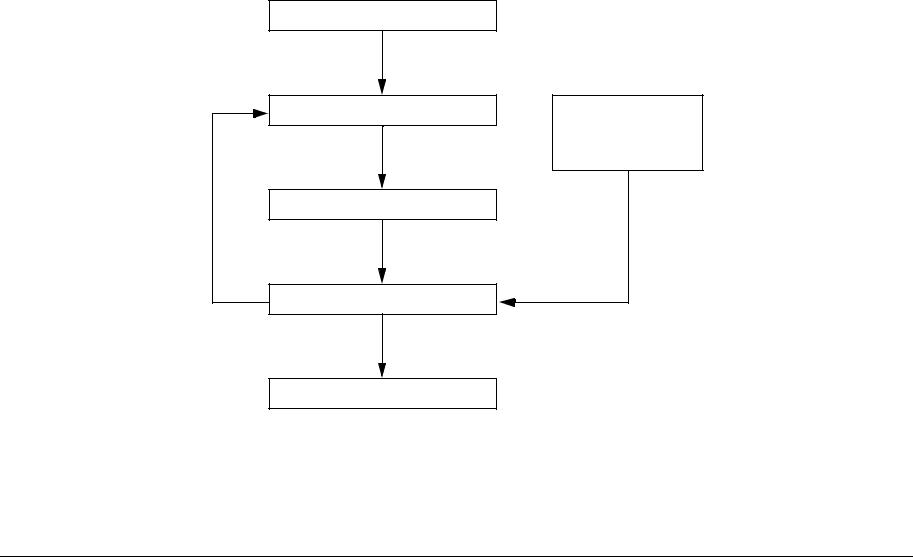
Fault Repair Overview
The fault repair operation proceeds in the following flow. After performing the pre-check, verify the symptoms and refer to the Error Code List and Section 7 Wiring Data to effectively repair the fault:
Check the status of Installation
Check the problem status
Perform RAP
Check if the fault is repaired
Completed
Diagnostic Mode
Operating Principles
Wiring Data
Reference
Information
Figure 1 Troubleshooting Procedure
|
Reissue |
June, 2008 |
Status Indicator RAPS |
|
WorkCentre 5016, 5020 |
2-3 |

Check the Status of Installation
Before starting to troubleshoot, always check the following items:
•The voltage of the power supply (measure the voltage at the power outlet to see if it is within specification).
•The power cord for damage, short circuits, open circuits, and wrong internal connections.
•The machine for proper grounding.
•The machine is not installed in a place with high temperature, high humidity, low temperature, low humidity, or a place with drastic changes in temperature.
•The machine is not installed near a water outlet, humidifier, heater or fire source, dusty areas, or under the direct draft of an air conditioner.
•The machine is not installed in a place where volatile or flammable gas is generated.
•The machine is not installed in a place exposed to direct sunlight.
•The machine is installed in a well-ventilated place.
•The machine is installed on a stable level surface.
•The paper is within specification (standard paper is recommended).
•The machine for any improper handling.
•The Periodic Replacement Parts are replaced at the proper intervals.
Safety Considerations
•Before servicing, always unplug the power cord unless required otherwise. When the power is turned ON, never touch a current-carrying part unless required otherwise. Also, since current is carried in the LVPS power switch/inlet even when the power is turned OFF, never touch this area.
•When turning the power ON to perform a check while the Interlock Switch or Security Switch is also turned ON and the covers are removed, always disconnect the connector ( P/J140) that is connected to the ROS, unless required otherwise, because a laser beam might be emitted from the ROS.
•When connecting the connector ( P/J520) on the HVPS according to the instructions in the RAP, never touch the HVPS and high-voltage output parts.
•When performing a high voltage output check using the Input Diagnostics or Output Diagnostics in Diagnostic Mode, make sure that all covers are installed unless specified otherwise. Also, never touch any high voltage output section when performing the high voltage output check.
•When operating the Drive Section using the Input Diagnostics or Output Diagnostics in Diagnostic Mode, make sure that all covers are installed unless specified otherwise. Also, never touch the Drive Section while operating it.
•Be careful not to burn yourself when touching parts that can get very hot.
•When servicing, use a grounded wrist band to remove static electricity from your body.
Things to Note When Using RAPs
•When troubleshooting using RAPs, prepare normally working parts such as the AIOC PWB, LVPS, HVPS and Fuser in advance because they might be required to identify a failure. In addition, if the fault cannot be repaired, replace the «parts considered to be the cause» and related parts in sequence and check the operation.
•When servicing, always disconnect the power cord unless required otherwise. When the power cord is connected, never touch any current-carrying part unless absolutely necessary.
•Descriptions related to connectors are expressed as follows: “P/J12″ -> The connector (P/ J12) is in the connected state. «P12» -> The plug side when the connector (P/J12) is in the disconnected state (except when it is directly connected to a board). «J12» -> The jack side when the connector (P/J12) is in the disconnected state (except when it is directly connected to a board).
•In a RAP, «P/J1 <=> P/J2» means that all the opposing pins between «P/J1» and «P/J12» (refer to Section 7, Wiring Data) should be measured.
•The voltages on small connectors are measured using a special tool. Handle the tool carefully because it has a sharp tip.
•The numerical values described in the RAPs are for reference only. Approximate values are considered to be the same.
•Note that for the checks specified in the RAP, you must check the references for the parts that must be removed and their procedures.
•«Replacement» in the RAPs indicates the parts that are considered to be the cause of the problem. Check by replacing the parts and, if necessary, the assembly that contains those parts.
•In the RAPs, the highest level paper supply is called «Tray 1,» and the one below it is called «Tray 2.»
•In the RAPs, some procedures are described separately for each specification. Follow the instructions for your model to repair the faults.
RAP Flow
RAPs are a good place to start in diagnosing a failure. RAPs guide you through the troubleshooting process by checking for the presence of error codes and other types of problematic symptoms. To troubleshoot problems related to image quality, refer to Section 3 Image Quality Troubleshooting.
|
Status Indicator RAPS |
June, 2008 |
Reissue |
|
2-4 |
WorkCentre 5016, 5020 |
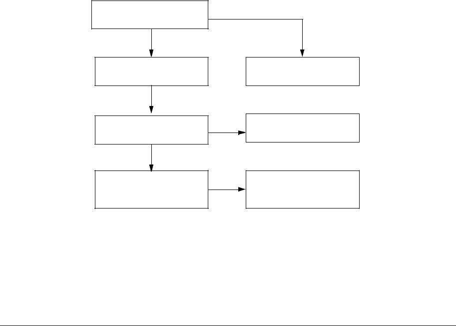
Ask the operator about the problem
Did the operator operate the machine correctly?
Yes
Turn the Power Switch OFF then ON
Does the error recur when operating the machine in the same way as before (when the problem originally occurred)?
Yes
Does the Control Panel display an Error Code?
Explain how to operate the machine
Procedure is complete
Refer to the Error Code List and perform the relevant troubleshooting
Figure 2 RAP Flow
|
Reissue |
June, 2008 |
Status Indicator RAPS |
|
WorkCentre 5016, 5020 |
2-5 |

Error Code List
NOTE: In the “Record in Error Log” column, “O” = yes and “X” = no.
|
Error |
Record in |
|||||
|
Code |
Error Name/Explanation/I/O Diagnostic Codes/Check Items |
Error Log |
RAP |
BSD |
||
|
Error Name |
||||||
|
Tray1 F/O#1 SNR on JAM |
||||||
|
Explanation |
||||||
|
Timeout between Tray1 Feed Clutch ON and Tray1 Feed Sensor ON. |
||||||
|
I/O Diagnostic Codes (How to Enter the Diagnostic Mode) |
||||||
|
• |
[08-07] Tray1 Feed Sensor |
|||||
|
• |
[08-12] Tray1 Feed Clutch |
|||||
|
Check Items |
||||||
|
• |
Feed Roll or Retard Pad dirty, contaminated with paper dust, worn, or faulty |
|||||
|
• |
Tray1 Feed Sensor dirty and Sensor Actuator deformed or damaged |
CH8.1 |
||||
|
C1-1 |
• |
Paper damaged, not within specification, or not loaded correctly |
O |
— |
||
|
Figure 1 |
||||||
|
• |
Foreign matter, burrs, or paper in the paper path |
|||||
|
• |
Drive gear worn or damaged |
|||||
|
• |
Tray1 Feed Clutch faulty |
|||||
|
• |
Check that the following wires are connected securely with good electrical contact. If there is no problem, replace the Tray 1 Feed Sensor |
|||||
|
(PL 2.5)(REP 2.5.1). |
||||||
|
– Wire between Tray 1 Feed Sensor J158-3 ( P/J158) and LVPS J501-6 ( P/J501) |
||||||
|
– Wire between Tray 1 Feed Sensor J158-2 and LVPS J501-7 |
||||||
|
– Wire between Tray 1 Feed Sensor J158-1 and LVPS J501-8 |
||||||
|
• |
Replace the Tray1 Feed Clutch (PL 2.2) (REP 2.2.1) and the AIOC PWB (PL 8.1) (REP 8.1.1) in that order. |
|||||
|
Status Indicator RAPS |
June, 2008 |
Reissue |
|
2-6 |
WorkCentre 5016, 5020 |
![]()
|
Error |
Record in |
||
|
Code |
Error Name/Explanation/I/O Diagnostic Codes/Check Items |
Error Log RAP |
BSD |
|
Error Name |
|||
|
Tray1 Regi SNR on JAM |
|||
|
Explanation |
|||
|
Timeout between Tray1 Feed Sensor ON and IOT Registration Sensor ON. |
|||
|
I/O Diagnostic Codes (How to Enter the Diagnostic Mode) |
•[08-07] Tray1 Feed Sensor
•[08-05] IOT Registration Sensor
•[08-10] IOT Registration Clutch
|
Check Items |
||||||
|
• |
Take Away Roll 1 dirty, contaminated with paper dust, worn, or faulty |
|||||
|
• |
Tray1 Feed Sensor dirty and Sensor Actuator deformed or damaged |
|||||
|
• |
Paper damaged, not within specification, or not loaded correctly |
CH8.1 |
||||
|
• |
Foreign matter, burrs, or paper in the paper path |
|||||
|
C1-2 |
O |
— |
Figure 1 |
|||
|
• |
Drive gear worn or damaged |
CH8.4 |
||||
|
• |
IOT Registration Clutch faulty |
Figure 4 |
•Check that the following wires are connected securely with good electrical contact. If there is no problem, replace the Tray 1 Feed Sensor (PL 2.5) (REP 2.5.1).
–Wire between Tray 1 Feed Sensor J158-3 ( P/J158) and LVPS J501-6 ( P/J501)
–Wire between Tray 1 Feed Sensor J158-2 and LVPS J501-7
–Wire between Tray 1 Feed Sensor J158-1 and LVPS J501-8
•Check that the following wires are connected securely with good electrical contact. If there is no problem, replace the IOT Registration Sensor (PL 2.9).
— Wire between IOT Registration Sensor J156-3 ( P/J156) and LVPS J503-1 ( P/J503) — Wire between IOT Registration Sensor J156-2 and LVPS J503-2
— Wire between IOT Registration Sensor J156-1 and LVPS J503-3
•Replace the IOT Registration Clutch (PL 2.9) and the AIOC PWB (PL 8.1) (REP 8.1.1) in that order.
|
Reissue |
June, 2008 |
Status Indicator RAPS |
|
WorkCentre 5016, 5020 |
2-7 |

|
Error |
Record in |
||||
|
Code |
Error Name/Explanation/I/O Diagnostic Codes/Check Items |
Error Log |
RAP |
BSD |
|
|
Error Name |
|||||
|
STM F/O#2 SNR on JAM |
|||||
|
Explanation |
|||||
|
Timeout between STM Feed Motor ON and STM Feed Sensor ON. |
|||||
|
I/O Diagnostic Codes (How to Enter the Diagnostic Mode) |
|||||
|
• [08-06] STM Feed Sensor |
|||||
|
• [08-11] STM Feed Clutch |
|||||
|
• [08-13] STM Feed Motor |
|||||
|
Check Items |
|||||
|
• Tray2 Feed Roll or Tray2 Retard Roll dirty, contaminated with paper dust, worn, or faulty |
|||||
|
• STM Feed Sensor dirty and Sensor Actuator deformed or damaged |
|||||
|
C2-1 |
• Paper damaged, not within specification, or not loaded correctly |
O |
— |
CH8.2 |
|
|
Figure 2 |
|||||
|
• Foreign matter, burrs, or paper in the paper path |
|||||
|
• Drive gear worn or damaged |
|||||
|
• STM Feed Clutch faulty |
|||||
|
• STM Feed Motor faulty |
|||||
|
• Check that the following wires are connected securely with good electrical contact. If there is no problem, replace the STM Feed Sensor (PL |
|||||
|
11.5) (REP 11.5.1 ). |
|||||
|
– — Wire between STM Feed Sensor J172-3 ( P/J172) and STM PWB J542-6 ( P/J542) |
|||||
|
– — Wire between STM Feed Sensor J172-2 and STM PWB J542-7 |
|||||
|
– — Wire between STM Feed Sensor J172-1 and STM PWB J542-8 |
|||||
|
• Replace the STM Feed Clutch (PL 11.6) (REP 11.6.1), the STM Feed Motor (PL 11.6) (REP 11.6.2), and the STM PWB (PL 11.5) (REP |
|||||
|
11.5.2 ) in that order. |
|||||
|
Status Indicator RAPS |
June, 2008 |
Reissue |
|
2-8 |
WorkCentre 5016, 5020 |

|
Error |
Record in |
||
|
Code |
Error Name/Explanation/I/O Diagnostic Codes/Check Items |
Error Log RAP |
BSD |
|
Error Name |
|||
|
Tray1 F/O#1 SNR on JAM from STM feed |
|||
|
Explanation |
|||
|
Timeout between STM Feed Out Sensor ON and Tray 1 Feed Out Sensor ON. |
|||
|
I/O Diagnostic Codes (How to Enter the Diagnostic Mode) |
•[08-06] STM Feed Sensor
•[08-07] Tray1 Feed Sensor
•[08-11] STM Feed Clutch
•[08-13] STM Feed Motor
Check Items
•Take Away Roll 2 dirty, contaminated with paper dust, worn, or faulty
•STM Feed Sensor dirty and Sensor Actuator deformed or damaged
•Paper damaged, not within specification, or not loaded correctly
|
• |
Foreign matter, burrs, or paper in the paper path |
CH8.1 |
||||
|
C2-2 |
• |
Drive gear worn or damaged |
O |
— |
Figure 1 |
|
|
CH8.2 |
||||||
|
• |
STM Feed Clutch faulty |
|||||
|
Figure 2 |
||||||
•STM Feed Motor faulty
•Check that the following wires are connected securely with good electrical contact. If there is no problem, replace the STM Feed Sensor (PL 11.5) (REP 11.5.1).
–Wire between STM Feed Sensor J172-3 ( P/J172) and STM PWB J542-6 ( P/J542)
–Wire between STM Feed Sensor J172-2 and STM PWB J542-7
–Wire between STM Feed Sensor J172-1 and STM PWB J542-8
•Check that the following wires are connected securely with good electrical contact. If there is no problem, replace the Tray 1 Feed Sensor (PL 2.5) (REP 2.5.1).
–Wire between Tray 1 Feed Sensor J158-3 ( P/J158) and STM PWB J501-6 ( P/J501)
–Wire between Tray 1 Feed Sensor J158-2 and STM PWB J501-7
–Wire between Tray 1 Feed Sensor J158-1 and STM PWB J501-8
•Replace the STM Feed Clutch (PL 11.6) (REP 11.6.1), the STM Feed Motor (PL 11.6) (REP 11.6.2), and the STM PWB (PL 11.5) (REP 11.5.2) in that order.
|
Reissue |
June, 2008 |
Status Indicator RAPS |
|
WorkCentre 5016, 5020 |
2-9 |

|
Error |
Record in |
||
|
Code |
Error Name/Explanation/I/O Diagnostic Codes/Check Items |
Error Log RAP |
BSD |
|
Error Name |
|||
|
STM Regi SNR on JAM |
Explanation
•When feeding paper from the STM, timeout between Tray1 Feed Sensor ON and IOT Registration Sensor ON.
I/O Diagnostic Codes (How to Enter the Diagnostic Mode)
•[08-05] IOT Registration Sensor
•[08-10] IOT Registration Clutch
Check Items
•Take Away Roll 1 dirty, contaminated with paper dust, worn, or faulty
•IOT Registration Sensor dirty and Sensor Actuator deformed or damaged
•Paper damaged, not within specification, or not loaded correctly
|
• |
Foreign matter, burrs, or paper in the paper path |
CH8.1 |
||||
|
C2-3 |
• |
Drive gear worn or damaged |
O |
— |
Figure 1 |
|
|
CH8.4 |
||||||
|
• |
IOT Registration Clutch faulty |
|||||
|
Figure 4 |
||||||
•Check that the following wires are connected securely with good electrical contact. If there is no problem, replace the Tray 1 Feed Sensor (PL 2.5) (REP 2.5.1).
–Wire between Tray 1 Feed Sensor J158-3 ( P/J158) and LVPS J501-6 ( P/J502)
–Wire between Tray 1 Feed Sensor J158-2 and LVPS J501-7
–Wire between Tray 1 Feed Sensor J158-1 and LVPS J501-8
•Check that the following wires are connected securely with good electrical contact. If there is no problem, replace the IOT Registration Sensor (PL 2.9).
–Wire between Tray 1 Feed Sensor J156-3 ( P/J156) and LVPS J503-1 ( P/J503)
–Wire between Tray 1 Feed Sensor J156-2 and LVPS J503-2
–Wire between Tray 1 Feed Sensor J156-1 and LVPS J503-3
•Replace the IOT Registration Clutch (PL 2.9) and the AIOC PWB (PL 8.1) (REP 8.1.1) in that order.
|
Error Name |
|||||
|
No paper in the selected paper tray (Tray1) |
|||||
|
Explanation |
|||||
|
• |
No paper is detected in Tray1 when ATS function is disabled and Tray1 is selected during a copy job. |
||||
|
• |
No paper is detected in Tray1 when Tray1 is selected during a print job (the paper size setting matches the one specified for the job). |
||||
|
I/O Diagnostic Codes |
|||||
|
[07-07] Tray1 No Paper Sensor |
|||||
|
Check Items |
CH7.1 |
||||
|
C5-0 |
• |
Press the [Stop] button on the Control Panel. |
X |
— |
|
|
Figure 1 |
|||||
|
• |
Check the tray to see if it is empty; if it is, add paper specified by the job. |
||||
|
• |
Tray1 No Paper Sensor dirty and Sensor Actuator deformed or damaged |
||||
|
• |
Check that the following wires are connected securely with good electrical contact. If there is no problem, replace the Tray 1 No Paper Sen- |
||||
|
sor (PL 2.7) (REP 2.7.1). |
|||||
|
– Wire between Tray1 No Paper Sensor J157-3 ( P/J157) and LVPS J501-3 ( P/J501) |
|||||
|
– Wire between Tray1 No Paper Sensor J157-2 and LVPS J501-4 |
|||||
|
– Wire between Tray1 No Paper Sensor J157-1 and LVPS J501-5 |
|||||
|
• |
Replace the AIOC PWB (PL 8.1) (REP 8.1.1). |
|
Status Indicator RAPS |
June, 2008 |
Reissue |
|
2-10 |
WorkCentre 5016, 5020 |

|
Error |
Record in |
|||||
|
Code |
Error Name/Explanation/I/O Diagnostic Codes/Check Items |
Error Log |
RAP |
BSD |
||
|
Error Name |
||||||
|
Tray1 Paper Size Mismatch |
||||||
|
Explanation |
||||||
|
C5-1 |
• |
Paper that is different from the one in the Tray Settings is detected when feeding. |
X |
— |
— |
|
|
• |
Or, paper size setting in Tray1 is different from the paper size specification of the job when Tray1 is selected during a print job. |
|||||
|
Check Items |
||||||
|
• |
Press the [Stop] button on the Control Panel. |
|||||
|
• |
Change the paper size of Tray 1 to the one specified by the job. |
|||||
|
Error Name |
||||||
|
No paper in the selected paper tray (Tray2) |
||||||
|
Explanation |
||||||
|
• |
No paper is detected in the STM when ATS function is disabled and STM is selected during a copy job. |
|||||
|
• |
No paper is detected in the STM when STM is selected during a print job (the paper size setting matches the one specified for the job). |
|||||
|
I/O Diagnostic Codes (How to Enter the Diagnostic Mode) |
||||||
|
[07-08] STM No Paper Sensor |
||||||
|
Check Items |
CH7.2 |
|||||
|
C6-0 |
• |
Press the [Stop] button on the Control Panel. |
X |
— |
||
|
Figure 2 |
||||||
|
• |
Load the correct paper into the STM. |
|||||
|
• |
STM No Paper Sensor dirty and Sensor Actuator deformed or damaged. |
|||||
|
• |
Check that the following wires are connected securely with good electrical contact. If there is no problem, replace the STM No Paper Sen- |
|||||
|
sor (PL 11.7) (REP 11.7.1). |
||||||
|
– Wire between STM No Paper Sensor J171-3 ( P/J171) and STM PWB J542-3 ( P/J542) |
||||||
|
– Wire between STM No Paper Sensor J171-2 and STM PWB J542-4 |
||||||
|
– Wire between STM No Paper Sensor J171-1 and STM PWB J542-5 |
||||||
|
• |
Replace the STM PWB (PL 11.5) (REP 11.5.2) and the AIOC PWB (PL 8.1) (REP 8.1.1). |
|||||
|
Error Name |
||||||
|
Tray2 Paper Size Mismatch |
||||||
|
Explanation |
||||||
|
C6-1 |
• |
Paper that is different from the one in the Tray Settings is detected when feeding. |
X |
— |
— |
|
|
• |
Or, paper size setting in the STM is different from the paper size specification of the job when STM is selected during a print job. |
|||||
|
Check Items |
||||||
|
• |
Press the [Stop] button on the Control Panel. |
|||||
|
• |
Change the paper size of STM to the one specified by the job. |
|||||
|
Error Name |
||||||
|
MSI Paper Size Mismatch |
||||||
|
Explanation |
||||||
|
C7-1 |
• |
Paper that is different from the one in the Tray Settings is detected when feeding. |
X |
— |
— |
|
|
• |
Or, paper size setting in the MSI is different from the paper size specification of the job when MSI is selected during a print job. |
|||||
|
Check Items |
||||||
|
• |
Press the [Stop] button on the Control Panel. |
|||||
|
• |
Change the paper size of Bypass to the one specified by the job. |
|||||
|
Reissue |
June, 2008 |
Status Indicator RAPS |
|
WorkCentre 5016, 5020 |
2-11 |

|
Error |
Record in |
|||||
|
Code |
Error Name/Explanation/I/O Diagnostic Codes/Check Items |
Error Log |
RAP |
BSD |
||
|
Error Name |
||||||
|
APS NG Unselected |
||||||
|
Explanation |
||||||
|
• |
Either Tray 1 or STM is in one of the «paper settings is of a size that causes missing image» states when APS is selected during a copy job. |
CH3.2 |
||||
|
C0-1 |
• |
Or, either Tray 1 or STM is «set with paper size that is different from the one specified for the job» when Auto Tray is selected during a print |
X |
— |
||
|
Figure 2 |
||||||
|
job. |
||||||
|
Check Items |
||||||
|
• |
Press the [Stop] button on the Control Panel. |
|||||
|
• |
Change the paper size of Tray 1 or STM to the one specified by the job. |
|||||
|
Error Name |
||||||
|
MSI Regi SNR on JAM |
||||||
|
Explanation |
||||||
|
Timeout between Bypass Solenoid ON and IOT Registration Sensor ON. |
||||||
|
I/O Diagnostic Codes (How to Enter the Diagnostic Mode) |
||||||
|
• |
[08-05] IOT Registration Sensor |
|||||
|
• |
[08-17] Bypass Solenoid |
|||||
|
Check Items |
||||||
|
• |
Bypass Feed Roll, Retard Pad, or Bypass Take Away Roll dirty, contaminated with paper dust, worn, or faulty |
|||||
|
• |
IOT Registration Sensor dirty and Sensor Actuator deformed or damaged |
CH8.3 |
||||
|
• |
Paper damaged, not within specification, or not loaded correctly |
|||||
|
C9-3 |
O |
— |
Figure 3 |
|||
|
• |
Foreign matter, burrs, or paper in the paper path |
CH8.4 |
||||
|
• |
Drive gear worn or damaged |
Figure 4 |
||||
|
• |
Bypass Solenoid faulty |
|||||
|
• |
Check that the following wires are connected securely with good electrical contact. If there is no problem, replace the IOT Registration Sen- |
|||||
|
sor (PL 2.9). |
||||||
|
– Wire between Tray 1 Feed Sensor J156-3 ( P/J156) and LVPS J503-1 ( P/J503) |
||||||
|
– Wire between Tray 1 Feed Sensor J156-2 and LVPS J503-2 |
||||||
|
– Wire between Tray 1 Feed Sensor J156-1 and LVPS J503-3 |
||||||
|
• |
Check that the Bypass Solenoid and the LVPS J502-1/3 ( P/J502) pins are connected securely with good electrical contact. If there is no |
|||||
|
problem, replace the Bypass Solenoid (PL 7.5). |
||||||
|
• |
Replace the AIOC PWB (PL 8.1) (REP 8.1.1). |
|||||
|
Status Indicator RAPS |
June, 2008 |
Reissue |
|
2-12 |
WorkCentre 5016, 5020 |

|
Error |
Record in |
||||
|
Code |
Error Name/Explanation/I/O Diagnostic Codes/Check Items |
Error Log |
RAP |
BSD |
|
|
Error Name |
|||||
|
F/O#1 SNR Static JAM |
|||||
|
Explanation |
|||||
|
Tray1 Feed Sensor ON is detected during standby. |
|||||
|
I/O Diagnostic Codes (How to Enter the Diagnostic Mode) |
|||||
|
[08-07] Tray1 Feed Sensor |
|||||
|
Check Items |
CH8.1 |
||||
|
C8-1 |
• |
Tray1 Feed Sensor dirty and Sensor Actuator deformed or damaged |
O |
— |
|
|
Figure 1 |
|||||
|
• |
Foreign matter, burrs, or paper in the paper path |
||||
|
• |
Check that the following wires are connected securely with good electrical contact. If there is no problem, replace the Tray 1 Feed Sensor |
||||
|
(PL 2.5) (REP 2.5.1). |
|||||
|
– Wire between Tray 1 Feed Sensor J158-3 ( P/J158) and STM PWB J501-6 ( P/J501) |
|||||
|
– Wire between Tray 1 Feed Sensor J158-2 and STM PWB J501-7 |
|||||
|
– Wire between Tray 1 Feed Sensor J158-1 and STM PWB J501-8 |
|||||
|
• |
Replace the AIOC PWB (PL 8.1) (REP 8.1.1). |
||||
|
Error Name |
|||||
|
F/O#2 SNR Static JAM |
|||||
|
Explanation |
|||||
|
STM Feed Sensor ON is detected during standby. |
|||||
|
I/O Diagnostic Codes (How to Enter the Diagnostic Mode) |
|||||
|
[08-06] STM Feed Sensor |
|||||
|
Check Items |
CH8.2 |
||||
|
C8-2 |
• |
STM Feed Sensor dirty and Sensor Actuator deformed or damaged |
O |
— |
|
|
Figure 2 |
|||||
|
• |
Foreign matter, burrs, or paper in the paper path |
||||
|
• |
Check that the following wires are connected securely with good electrical contact. If there is no problem, replace the STM Feed Sensor (PL |
||||
|
11.5) (REP 11.5.1). |
|||||
|
– Wire between STM Feed Sensor J172-3 ( P/J172) and STM PWB J542-6 ( P/J542) |
|||||
|
– Wire between STM Feed Sensor J172-2 and STM PWB J542-7 |
|||||
|
– Wire between STM Feed Sensor J172-1 and STM PWB J542-8 |
|||||
|
• |
Replace the STM PWB (PL 11.5) (REP 11.5.2) and the AIOC PWB (PL 8.1) (REP 8.1.1) in that order. |
||||
|
Error Name |
|||||
|
CPM Image Lost |
|||||
|
E0-1 |
Explanation |
O |
— |
— |
|
|
During a copy job in CMP Priority Mode, it is detected that the paper containing an image cannot be output after the image is deleted. |
|||||
|
Check Items |
|||||
|
Press the [Stop] button on the Control Panel. |
|||||
|
Reissue |
June, 2008 |
Status Indicator RAPS |
|
WorkCentre 5016, 5020 |
2-13 |

|
Error |
Record in |
|||||
|
Code |
Error Name/Explanation/I/O Diagnostic Codes/Check Items |
Error Log |
RAP |
BSD |
||
|
Error Name |
||||||
|
Regi SNR Static JAM |
||||||
|
Explanation |
||||||
|
IOT Registration Sensor ON is detected during standby. |
||||||
|
I/O Diagnostic Codes (How to Enter the Diagnostic Mode) |
||||||
|
[08-05] IOT Registration Sensor |
||||||
|
Check Items |
CH8.4 |
|||||
|
E1-6 |
• |
Sensor dirty |
O |
— |
||
|
Figure 4 |
||||||
|
• |
Foreign matter, burrs, or paper in the paper path |
|||||
|
• |
Check that the following wires are connected securely with good electrical contact. If there is no problem, replace the IOT Registration Sen- |
|||||
|
sor (PL 2.9). |
||||||
|
– Wire between Tray 1 Feed Sensor J156-3 ( P/J156) and LVPS J503-1 ( P/J503) |
||||||
|
– Wire between Tray 1 Feed Sensor J156-2 and LVPS J503-2 |
||||||
|
– Wire between Tray 1 Feed Sensor J156-1 and LVPS J503-3 |
||||||
|
• |
Replace the AIOC PWB (PL 8.1)(REP 8.1.1). |
|||||
|
Error Name |
||||||
|
Exit SNR JAM |
||||||
|
Explanation |
||||||
|
Fuser Exit Sensor ON is detected during standby. |
||||||
|
I/O Diagnostic Codes (How to Enter the Diagnostic Mode) |
||||||
|
[10-23] Fuser Exit Sensor |
||||||
|
Check Items |
CH10.2 |
|||||
|
E3-6 |
• |
Fuser Exit Sensor dirty and Sensor Actuator deformed or damaged |
O |
— |
||
|
Figure 2 |
||||||
|
• |
Foreign matter, burrs, or paper in the paper path |
|||||
|
• |
Check that the following wires are connected securely with good electrical contact. If there is no problem, replace the Fuser Exit Sensor (PL |
|||||
|
6.2). |
||||||
|
– |
Wire between Fuser Exit Sensor J153-3 ( P/J153) and LVPS J505-1 ( P/J505) |
|||||
|
– |
Wire between Fuser Exit Sensor J153-2 and LVPS J505-2 |
|||||
|
– |
Wire between Fuser Exit Sensor J153-1 and LVPS J505-3 |
|||||
|
• |
Replace the AIOC PWB (PL 8.1) (REP 8.1.1). |
|||||
|
Status Indicator RAPS |
June, 2008 |
Reissue |
|
2-14 |
WorkCentre 5016, 5020 |
|
Error |
Record in |
||||||
|
Code |
Error Name/Explanation/I/O Diagnostic Codes/Check Items |
Error Log |
RAP |
BSD |
|||
|
Error Name |
|||||||
|
IOT L/H Cover open |
|||||||
|
Explanation |
|||||||
|
The Left Hand Cover is open. |
|||||||
|
I/O Diagnostic Codes (How to Enter the Diagnostic Mode) |
|||||||
|
[01-01] LH Cover Interlock Switch |
|||||||
|
E5-1 |
Check Items |
X |
— |
CH1.2 |
|||
|
• |
Check that the Left Hand Cover closes correctly. |
Figure 2 |
|||||
|
• |
Check that the LH Cover Interlock Switch is correctly installed and that the electrical connection is good. |
||||||
|
• |
Check that the following wires are connected securely with good electrical contact. If there is no problem, replace the LH Cover Interlock |
||||||
|
Switch (PL 8.2). |
|||||||
|
– Wire between LH Cover Interlock Switch FS151 ( FS151) and LVPS J506-4 ( P/J506) |
|||||||
|
– Wire between LH Cover Interlock Switch FS152 ( FS152) and LVPS J506-3 |
|||||||
|
• |
Replace the LVPS (PL 8.1) (REP 8.1.2) and the AIOC PWB (PL 8.1) (REP 8.1.1) in that order. |
||||||
|
Error Name |
|||||||
|
IOT Front Cover open |
|||||||
|
Explanation |
|||||||
|
The Front Cover is open. |
|||||||
|
I/O Diagnostic Codes (How to Enter the Diagnostic Mode) |
|||||||
|
[01-12] Front Cover Interlock Switch |
|||||||
|
E5-2 |
Check Items |
X |
— |
CH1.2 |
|||
|
• |
Check that the Front Cover closes correctly. |
Figure 2 |
|||||
|
• |
Check that the Front Cover Interlock Switch is correctly installed and that the electrical connection is good. |
||||||
|
• |
Check that the following wires are connected securely with good electrical contact. If there is no problem, replace the Front Cover Interlock |
||||||
|
Switch (PL 8.2). |
|||||||
|
– Wire between Front Cover Interlock Switch FS153 ( FS153) and LVPS J506-2 ( P/J506) |
|||||||
|
– Wire between Front Cover Interlock Switch FS154 ( FS154) and LVPS J506-1 |
|||||||
|
• |
Replace the LVPS (PL 8.1) (REP 8.1.2) and the AIOC PWB (PL 8.1) (REP 8.1.1) in that order. |
||||||
|
Error Name |
|||||||
|
L/H Low Cover open |
|||||||
|
Explanation |
|||||||
|
Access Cover 1 is open. |
|||||||
|
I/O Diagnostic Codes (How to Enter the Diagnostic Mode) |
|||||||
|
[01-11] Tray1 Interlock Switch |
|||||||
|
E6-1 |
Check Items |
X |
— |
CH7.1 |
|||
|
• |
Check that Access Cover 1 closes correctly. |
Figure 1 |
|||||
|
• |
Check that the Tray 1 Interlock Switch is correctly installed and that the electrical connection is good. |
||||||
|
• |
Check that the following wires are connected securely with good electrical contact. If there is no problem, replace the Tray 1 Interlock |
||||||
|
Switch (PL 2.5). |
|||||||
|
– Wire between Tray 1 Interlock Switch J161-2 ( P/J161) and LVPS J501-9 ( P/J501) |
|||||||
|
– Wire between Tray 1 Interlock Switch J161-1 and LVPS J501-10 |
|||||||
|
• |
Replace the LVPS (PL 8.1) (REP 8.1.2) and the AIOC PWB (PL 8.1) (REP 8.1.1) in that order. |
||||||
|
Reissue |
June, 2008 |
Status Indicator RAPS |
|||||
|
WorkCentre 5016, 5020 |
2-15 |

|
Error |
Record in |
|||||
|
Code |
Error Name/Explanation/I/O Diagnostic Codes/Check Items |
Error Log |
RAP |
BSD |
||
|
Error Name |
||||||
|
STM L/H Cover open |
||||||
|
Explanation |
||||||
|
Access Cover 2 is open. |
||||||
|
I/O Diagnostic Codes (How to Enter the Diagnostic Mode) |
||||||
|
[01-10] STM Interlock Switch |
||||||
|
E6-2 |
Check Items |
X |
— |
CH7.2 |
||
|
• |
Check that Access Cover 2 closes correctly. |
Figure 2 |
||||
|
• |
Check that the STM Interlock Switch is correctly installed and that the electrical connection is good. |
|||||
|
• |
Check that the following wires are connected securely with good electrical contact. If there is no problem, replace the STM Interlock Switch |
|||||
|
(PL 11.5). |
||||||
|
– Wire between STM Interlock Switch J173-2 ( P/J173) and STM PWB J542-9 ( P/J542) |
||||||
|
– Wire between STM Interlock Switch J173-1 and STM PWB J542-10 |
||||||
|
• |
Replace the STM PWB (PL 11.5) (REP 11.5.2), the LVPS (PL 8.1) (REP 8.1.2), and the AIOC PWB (PL 8.1) (REP 8.1.1) in that order. |
|||||
|
Error Name |
||||||
|
Nup NG Out Of Range |
||||||
|
Explanation |
||||||
|
The magnification is not within the range of 50 to 200% during Nup. |
||||||
|
E8-1 |
Check Items |
X |
— |
CH3.2 |
||
|
• |
Press the [Stop] button on the Control Panel. |
Figure 2 |
||||
|
• |
Press the [Paper Supply] button on the Control Panel. |
|||||
|
• |
Press the [Special Copy] button on the Control Panel. |
|||||
|
• |
Press the [Original Size Input] button on the Control Panel. |
|||||
|
• |
Press the [Clear All] button on the Control Panel. |
|||||
|
Error Name |
||||||
|
Nup Paper direction mismatch |
||||||
|
Explanation |
||||||
|
The paper orientation of the document and the tray are not aligned during Nup. |
||||||
|
E8-2 |
Check Items |
X |
— |
CH3.2 |
||
|
• |
Press the [Stop] button on the Control Panel. |
Figure 2 |
||||
|
• |
Press the [Paper Supply] button on the Control Panel. |
|||||
|
• |
Press the [Special Copy] button on the Control Panel. |
|||||
|
• |
Press the [Original Size Input] button on the Control Panel. |
|||||
|
• |
Press the [Clear All] button on the Control Panel. |
|||||
|
Status Indicator RAPS |
June, 2008 |
Reissue |
|
2-16 |
WorkCentre 5016, 5020 |
![]()
|
Error |
Record in |
|||||
|
Code |
Error Name/Explanation/I/O Diagnostic Codes/Check Items |
Error Log |
RAP |
BSD |
||
|
Error Name |
||||||
|
Exit SNR on JAM |
||||||
|
Explanation |
||||||
|
Timeout between IOT Registration Clutch ON and Fuser Exit Sensor ON. |
||||||
|
I/O Diagnostic Codes (How to Enter the Diagnostic Mode) |
||||||
|
• |
[08-10] IOT Registration Clutch |
|||||
|
• |
[10-23] Fuser Exit Sensor |
|||||
|
Check Items |
||||||
|
• |
Registration Roll dirty, contaminated with paper dust, worn, or faulty |
|||||
|
• |
Fuser Exit Sensor dirty and Sensor Actuator deformed or damaged |
|||||
|
E1-2 |
• |
Paper damaged or not within specification |
O |
— |
CH10.2 |
|
|
• |
Foreign matter, burrs, or paper in the paper path |
Figure 2 |
||||
|
• |
Drive gear worn or damaged |
|||||
|
• |
IOT Registration Clutch faulty |
|||||
|
• |
Check that the IOT Registration Clutch and the LVPS J503-4/5 ( P/J503) pins are connected securely with good electrical contact. If there is |
|||||
|
no problem, replace the IOT Registration Clutch (PL 2.9). |
||||||
|
• |
Check that the following wires are connected securely with good electrical contact. If there is no problem, replace the Fuser Exit Sensor (PL |
|||||
|
6.2). |
||||||
|
– Wire between Fuser Exit Sensor J153-3 ( P/J153) and LVPS J505-1 ( P/J505) |
||||||
|
– Wire between Fuser Exit Sensor J153-2 and LVPS J505-2 |
||||||
|
– Wire between Fuser Exit Sensor J153-1 and LVPS J505-3 |
||||||
|
• |
Replace the AIOC PWB (PL 8.1) (REP 8.1.1). |
|||||
|
Error Name |
||||||
|
Exit SNR off JAM |
||||||
|
Explanation |
||||||
|
Timeout between Fuser Exit Sensor ON and Fuser Exit Sensor OFF. |
||||||
|
I/O Diagnostic Codes (How to Enter the Diagnostic Mode) |
||||||
|
[10-23] Fuser Exit Sensor |
||||||
|
Check Items |
||||||
|
• |
Fuser Exit Sensor dirty and Sensor Actuator deformed or damaged |
|||||
|
E3-1 |
• |
Paper damaged or not within specification |
O |
— |
CH10.2 |
|
|
Figure 2 |
||||||
|
• |
Foreign matter, burrs, or paper in the paper path |
|||||
|
• |
Drive gear worn or damaged |
|||||
|
• |
Check that the following wires are connected securely with good electrical contact. If there is no problem, replace the Fuser Exit Sensor (PL |
|||||
|
6.2). |
||||||
|
– Wire between Fuser Exit Sensor J153-3 ( P/J153) and LVPS J505-1 ( P/J505) |
||||||
|
– Wire between Fuser Exit Sensor J153-2 and LVPS J505-2 |
||||||
|
– Wire between Fuser Exit Sensor J153-1 and LVPS J505-3 |
||||||
|
• |
Replace the LVPS (PL 8.1) (REP 8.1.2) and the AIOC PWB (PL 8.1) (REP 8.1.1) in that order. |
|||||
|
Reissue |
June, 2008 |
Status Indicator RAPS |
|
WorkCentre 5016, 5020 |
2-17 |

|
Error |
Record in |
|||||
|
Code |
Error Name/Explanation/I/O Diagnostic Codes/Check Items |
Error Log |
RAP |
BSD |
||
|
Error Name |
||||||
|
• |
MCU-STM comm. error |
|||||
|
Explanation |
||||||
|
H9-7 |
A communication failure has occurred between the MCU and the Tray Module. |
O |
— |
CH3.1 |
||
|
Check Items |
Figure 1 |
|||||
|
• |
Turn the power OFF then ON. |
|||||
|
• |
Check for any open circuit or short circuit between the STM connectors. |
|||||
|
• |
Replace the STM PWB (PL 11.5) (REP 11.5.2) and the AIOC PWB (PL 8.1) (REP 8.1.1) in that order. |
|||||
|
Error Name |
||||||
|
Copy Counter Full |
||||||
|
L9-0 |
Explanation |
X |
— |
CH3.2 |
||
|
The user that is logged in has reached the allotted copy limit in the Account Mode. |
Figure 2 |
|||||
|
Check Items |
||||||
|
Press the [Stop] button on the Control Panel. |
||||||
|
Error Name |
||||||
|
Toner Cartridge was PRENEAR empty |
||||||
|
Explanation |
||||||
|
The toner cartridge is low. |
||||||
|
J1-0 |
Check Items |
X |
— |
— |
||
|
• |
Refill the toner. |
|||||
|
• |
Foreign matter on the sensor. |
|||||
|
• |
Check that the Toner Empty Sensor and the LVPS J509-1-4 ( P/J509) pins are connected securely with good electrical contact. If there is no |
|||||
|
problem, replace the Toner Empty Sensor (PL 4.2). |
||||||
|
• |
Replace the AIOC PWB (PL 8.1) (REP 8.1.1). |
|||||
|
Error Name |
||||||
|
Toner Empty |
||||||
|
Explanation |
||||||
|
The Toner Cartridge is empty. |
||||||
|
I/O Diagnostic Codes (How to Enter the Diagnostic Mode) |
||||||
|
J1-2 |
[09-07] Toner Empty Sensor |
O |
— |
CH9.2 |
||
|
Check Items |
Figure 2 |
|||||
|
• |
Refill the toner. |
|||||
|
• |
Foreign matter on the sensor. |
|||||
|
• |
Check that the Toner Empty Sensor and the LVPS J509 ( P/J509) 1-4 pins are connected securely with good electrical contact. If there is |
|||||
|
no problem, replace the Toner Empty Sensor (PL 4.2). |
||||||
|
• |
Replace the AIOC PWB (PL 8.1) (REP 8.1.1). |
|||||
|
Status Indicator RAPS |
June, 2008 |
Reissue |
|
2-18 |
WorkCentre 5016, 5020 |

|
Error |
Record in |
||||
|
Code |
Error Name/Explanation/I/O Diagnostic Codes/Check Items |
Error Log |
RAP |
BSD |
|
|
Error Name |
|||||
|
No Drum Cartridge |
|||||
|
Explanation |
|||||
|
Unable to detect the Drum Cartridge. |
|||||
|
I/O Diagnostic Codes (How to Enter the Diagnostic Mode) |
|||||
|
[09-02] Drum Cartridge |
|||||
|
Check Items |
|||||
|
• |
Turn the power OFF then ON. |
||||
|
J3-1 |
• |
Check that the following wires are connected securely with good electrical contact. If there is no problem, replace the Drum Cartridge (PL |
O |
— |
CH9.2 |
|
4.1) (REP 4.1.1). |
Figure 2 |
||||
|
– Wire between Drum Cartridge P610-7 ( P610) and AIOC PWB J402-1 ( P/J402) |
|||||
|
– Wire between Drum Cartridge P610-3 and AIOC PWB J402-4 |
|||||
|
– Wire between Drum Cartridge P610-2 and AIOC PWB J402-5 |
|||||
|
– Wire between Drum Cartridge P610-5 and AIOC PWB J402-2 |
|||||
|
– Wire between Drum Cartridge P610-4 and AIOC PWB J402-3 |
|||||
|
– Wire between Drum Cartridge P610-1 and AIOC PWB J402-6 |
|||||
|
• |
Replace the Drum Cartridge (PL 4.1) (REP 4.1.1) and the AIOC PWB (PL 8.1) (REP 8.1.1) in that order. |
||||
|
Error Name |
|||||
|
Drum near end of life |
|||||
|
J6-0 |
Explanation |
X |
— |
— |
|
|
The Drum Cartridge is near the end of its life. |
|||||
|
Check Items |
|||||
|
Replace the Drum Cartridge (PL 4.1) (REP 4.1.1). |
|||||
|
Error Name |
|||||
|
Drum cartridge life end |
|||||
|
J6-1 |
Explanation |
O |
— |
— |
|
|
The Drum Cartridge has reached the end of its life. |
|||||
|
Check Items |
|||||
|
Replace the Drum Cartridge (PL 4.1) (REP 4.1.1). |
|||||
|
Reissue |
June, 2008 |
Status Indicator RAPS |
|
WorkCentre 5016, 5020 |
2-19 |

|
Error |
Record in |
|||||
|
Code |
Error Name/Explanation/I/O Diagnostic Codes/Check Items |
Error Log |
RAP |
BSD |
||
|
Error Name |
||||||
|
Drum CRUM comm. Error |
||||||
|
Explanation |
||||||
|
The AIOC PWB is unable to communicate with the Drum Cartridge. |
||||||
|
I/O Diagnostic Codes (How to Enter the Diagnostic Mode) |
||||||
|
• |
[09-02] Drum Cartridge |
|||||
|
Check Items |
||||||
|
• |
Turn the power OFF then ON. |
|||||
|
J7-1 |
• |
Check that the following wires are connected securely with good electrical contact. If there is no problem, replace the Drum Cartridge (PL |
O |
— |
CH9.2 |
|
|
4.1) (REP 4.1.1). |
Figure 2 |
|||||
|
– Wire between Drum Cartridge P610-7 ( P610) and AIOC PWB J402-1 ( P/J402) |
||||||
|
– Wire between Drum Cartridge P610-3 and AIOC PWB J402-4 |
||||||
|
– Wire between Drum Cartridge P610-2 and AIOC PWB J402-5 |
||||||
|
– Wire between Drum Cartridge P610-5 and AIOC PWB J402-2 |
||||||
|
– Wire between Drum Cartridge P610-4 and AIOC PWB J402-3 |
||||||
|
– Wire between Drum Cartridge P610-1 and AIOC PWB J402-6 |
||||||
|
• |
Replace the Drum Cartridge (PL 4.1) (REP 4.1.1) and the AIOC PWB (PL 8.1) (REP 8.1.1) in that order. |
|||||
|
Error Name |
||||||
|
Drum CRUM Market Identity Mismatch |
||||||
|
Explanation |
CH9.2 |
|||||
|
J7-2 |
The AIOC PWB has detected that the Drum CRUM destination does not match. |
O |
— |
|||
|
Figure 2 |
||||||
|
Check Items |
||||||
|
• |
Turn the power OFF then ON. |
|||||
|
• |
Replace the Drum Cartridge (PL 4.1) (REP 4.1.1). |
|||||
|
Error Name |
||||||
|
Drum CRUM ID error |
||||||
|
Explanation |
CH9.2 |
|||||
|
J7-3 |
• |
The AIOC PWB has detected that the Drum CRUM ID is incorrect. |
O |
— |
||
|
Figure 2 |
||||||
|
Check Items |
||||||
|
• |
Turn the power OFF then ON. |
|||||
|
• |
Replace the Drum Cartridge (PL 4.1) (REP 4.1.1). |
|||||
|
Error Name |
||||||
|
EPC Memory Full |
||||||
|
Explanation |
||||||
|
N1-1 |
• |
During a copy job in Collate Mode, the EPC memory is full. |
O |
— |
— |
|
|
• |
Or, the machine has reached a state where it is unable to scan in any more documents. |
|||||
|
Check Items |
||||||
|
Press the [Stop] button on the Control Panel. |
||||||
|
Status Indicator RAPS |
June, 2008 |
Reissue |
|
2-20 |
WorkCentre 5016, 5020 |

|
Error |
Record in |
|||||
|
Code |
Error Name/Explanation/I/O Diagnostic Codes/Check Items |
Error Log |
RAP |
BSD |
||
|
Error Name |
||||||
|
No Response from USB-Host |
||||||
|
Explanation |
||||||
|
N4-0 |
• |
Either «USB disconnected» or «Communication timed-out» is detected during a print job. |
O |
— |
CH3.2 |
|
|
• |
Or, either «USB disconnected» or «Communication timed-out» is detected during a scan job. |
Figure 2 |
||||
|
Check Items |
||||||
|
• |
Cancel the print job. |
|||||
|
• |
Reconnect the USB cable correctly. |
|||||
|
Error Name |
||||||
|
HBPL or XPJL Syntax Error |
||||||
|
Explanation |
CH3.2 |
|||||
|
N4-1 |
An abnormal command that cannot be ignored is received from the USB-Host during a print job. |
O |
— |
|||
|
Figure 2 |
||||||
|
Check Items |
||||||
|
• |
Cancel the print job. |
|||||
|
• |
Reconnect the USB cable correctly. |
|||||
|
Error Name |
||||||
|
Download File Error |
||||||
|
N4-2 |
Explanation |
— |
||||
|
There is an abnormal Product ID or there is a checksum error in the download file. |
||||||
|
Check Items |
||||||
|
Press the [Stop] button on the Control Panel. |
||||||
|
Error Name |
||||||
|
Download Flash Write Error |
||||||
|
N4-3 |
Explanation |
— |
||||
|
Unable to write the downloaded file into flash memory. |
||||||
|
Check Items |
||||||
|
Press the [Stop] button on the Control Panel. |
||||||
|
Error Name |
||||||
|
CPM Image Lost |
||||||
|
E0-1 |
Explanation |
O |
— |
— |
||
|
During a copy job in CPM Priority Mode, the paper containing an image cannot be output after the image is deleted. |
||||||
|
Check Items |
||||||
|
Press the [Stop] button on the Control Panel. |
||||||
|
Error Name |
||||||
|
Push Scan TimeOut |
||||||
|
Explanation |
||||||
|
N5-0 |
• |
Push scan notification failed during a scan job. |
O |
— |
— |
|
|
• |
Or, there is no scan job request from the PC after a push scan notification. |
|||||
|
Check Items |
||||||
|
The error will clear itself after a set amount of time has passed. |
||||||
|
Reissue |
June, 2008 |
Status Indicator RAPS |
|
WorkCentre 5016, 5020 |
2-21 |

|
Error |
Record in |
|||||
|
Code |
Error Name/Explanation/I/O Diagnostic Codes/Check Items |
Error Log |
RAP |
BSD |
||
|
Error Name |
||||||
|
Controller Logic fail |
||||||
|
N9-0 |
Explanation |
O |
— |
CH3.2 |
||
|
A software defect that cannot be ignored is found in the Controller software. |
Figure 2 |
|||||
|
Check Items |
||||||
|
Turn the power OFF then ON. |
||||||
|
Error Name |
||||||
|
IOT Communication Error |
||||||
|
N9-1 |
Explanation |
O |
— |
CH3.2 |
||
|
The AIOC PWB has detected a Type-Di communication error. |
Figure 2 |
|||||
|
Check Items |
||||||
|
Turn the power OFF then ON. |
||||||
|
Error Name |
||||||
|
U0-1 |
Main Motor stop error |
O |
U0-1 |
CH4.1 |
||
|
Explanation |
Figure 1 |
|||||
|
The motor runs for over 120 seconds without any paper being fed. |
||||||
|
Error Name |
||||||
|
U1-1 |
Main Motor rotation error |
O |
U1-1 |
CH4.1 |
||
|
Explanation |
Figure 1 |
|||||
|
500ms after the IOT has started, the Main Motor Lock signal is «Low.» |
||||||
|
Error Name |
||||||
|
U2-1 |
Carriage Module Fail |
O |
U2-1 |
CH6.2 |
||
|
Explanation |
Figure 2 |
|||||
|
An abnormality was detected in the Carriage Module. |
||||||
|
Error Name |
||||||
|
Laser Power or ROS Motor Fail |
CH6.3 |
|||||
|
U3-5 |
Explanation |
O |
U3-5 |
|||
|
Figure 3 |
||||||
|
• |
The ROS Motor is unable to rotate. |
|||||
|
• |
Or, the laser output is not normal. |
|||||
|
Error Name |
||||||
|
Fuser On Time Fail |
CH10.1 |
|||||
|
U4-1 |
Explanation |
O |
U4-1 |
|||
|
Figure 1 |
||||||
|
• |
The lamp did not turn OFF within the specified time after turning ON. |
|||||
|
• |
Or, Warm Up was not completed within the specified time after power ON. |
|||||
|
Error Name |
||||||
|
U4-2 |
Over Heat Temp Fail |
O |
U4-2 |
CH10.1 |
||
|
Explanation |
Figure 1 |
|||||
|
A temperature above 250°C is continuously detected for 480ms. |
||||||
|
Error Name |
||||||
|
U4-3 |
FS1 thermistor defect |
O |
U4-3 |
CH10.1 |
||
|
Explanation |
Figure 1 |
|||||
|
FS1 cannot be monitored any more. |
||||||
|
Status Indicator RAPS |
June, 2008 |
Reissue |
|
2-22 |
WorkCentre 5016, 5020 |

|
Error |
Record in |
||||
|
Code |
Error Name/Explanation/I/O Diagnostic Codes/Check Items |
Error Log |
RAP |
BSD |
|
|
Error Name |
|||||
|
U4-9 |
Fuser Fan defect |
O |
U4-9 |
CH10.3 |
|
|
Explanation |
Figure 3 |
||||
|
After the start of Fan Fail Signal monitoring, the signal level was Low not more than 30 times. |
|||||
|
Error Name |
|||||
|
U6-2 |
RAM read/write check error |
O |
U6-2 |
CH3.2 |
|
|
Explanation |
Figure 2 |
||||
|
When the MCU runs the overall Read/Write check for RAM during startup, the Read Data and Write Data do not match. |
|||||
|
Error Name |
|||||
|
NVM data defect |
|||||
|
U6-3 |
Explanation |
O |
U6-3 |
CH3.2 |
|
|
• The NVM Header data ERROR and NVM 3 page data do not match. |
Figure 2 |
||||
|
• Or, unable to find the NVM Write & Read area. |
|||||
|
• The NVM or Counter areas are full. |
|||||
|
Error Name |
|||||
|
NVM read/write cannot be executed |
CH3.2 |
||||
|
U6-4 |
Explanation |
O |
U6-4 |
||
|
Figure 2 |
|||||
|
• An NVM Ack NG is detected during NVM Read. |
|||||
|
• An NVM Write Error is detected 5 times during NVM Recovery. |
|||||
|
Error Name |
|||||
|
U6-5 |
CPU Power to access NVM is not enough |
O |
U6-5 |
CH3.2 |
|
|
Explanation |
Figure 2 |
||||
|
NVM queue full is detected during NVM Write. |
|||||
|
Error Name |
|||||
|
U7-0 |
UI Communication TimeOut |
X |
U7-0 |
CH2.1 |
|
|
Explanation |
Figure 1 |
||||
|
At the Power On Sequence, the AIOC PWB did not communicate with the User Interface PWB. |
|||||
|
Error Name |
|||||
|
U7-1 |
UI Communication Error |
X |
U7-1 |
CH2.1 |
|
|
Explanation |
Figure 1 |
||||
|
The User Interface PWB has detected a communication failure. |
|||||
|
Error Name |
|||||
|
Billing Counter Defect |
CH3.2 |
||||
|
U8-1 |
Explanation |
O |
U8-1 |
||
|
Figure 2 |
|||||
|
• It is detected that the Billing Counter Value is incorrect. |
|||||
|
• Or, the AOIC PWB has failed to read the Billing Counter. |
|||||
|
Error Name |
|||||
|
U9-0 |
HVPS fail |
O |
U9-0 |
CH9.1 |
|
|
Explanation |
Figure 1 |
||||
|
A 500 msec cycle of the signal HVPS#ERR=High was detected twice in a row. |
|||||
|
Reissue |
June, 2008 |
Status Indicator RAPS |
|
WorkCentre 5016, 5020 |
2-23 |

Display Priority in Case of Multiple Errors
When multiple errors occur simultaneously, they will be shown on the Control Panel display in the following priority order. Always begin troubleshooting with the highest-priority error.
|
Priority |
Error |
|||
|
Order |
Code |
Error Name |
Error Characteristic |
|
|
1 |
U7-0 |
UI Communication TimeOut |
Unable to control the |
|
|
(Highest) |
display at the Control- |
|||
|
ler |
||||
|
2 |
U7-1 |
UI Communication Error |
||
|
3 |
H9-7 |
MCU-STM comm. error |
||
|
4 |
N9-1 |
IOT Communication Error |
||
|
5 |
N9-0 |
Controller Logic fail |
||
|
6 |
U0-1 |
Main Motor stop error |
||
|
7 |
U1-1 |
Main Motor rotation error |
||
|
8 |
U2-1 |
Carriage Module Fail |
||
|
9 |
U3-5 |
Laser Power or ROS Motor Fail |
||
|
10 |
U4-1 |
Fuser On Time Fail |
||
|
Fatal Error |
||||
|
11 |
U4-2 |
Over Heat Temp Fail |
||
|
12 |
U4-3 |
FS1 thermistor defect |
||
|
13 |
U4-9 |
Fuser Fan defect |
||
|
14 |
U6-2 |
RAM read/write check error |
||
|
15 |
U6-3 |
NVM data defect |
||
|
16 |
U6-4 |
NVM read/write cannot be executed |
||
|
17 |
U6-5 |
RAM read/write check error |
||
|
18 |
U8-1 |
Billing Counter Defect |
||
|
19 |
U9-0 |
HVPS fail |
||
|
20 |
E9-1 |
AMS NG Out Of Range |
||
|
21 |
E9-2 |
Paper direction mismatch |
||
|
22 |
E8-1 |
Nup NG Out Of Range |
||
|
23 |
E8-2 |
Nup Paper direction mismatch |
||
|
24 |
L9-0 |
Copy Counter Full |
Dynamic Error |
|
|
(Job Cancel) |
||||
|
25 |
N4-0 |
No Response from USB-Host |
||
|
26 |
N4-1 |
HBPL or XPJL Syntax Error |
||
|
27 |
N4-2 |
Download File Error |
||
|
27 |
N4-3 |
Download Flash Write Error |
||
|
29 |
N5-0 |
Push Scan TimeOut |
||
|
30 |
A5-1 |
Platen Cover Open |
Document Cover |
|
|
Open |
||||
|
32 |
E5-1 |
IOT L/H Cover open |
||
|
33 |
E5-2 |
IOT Front Cover open |
Paper Cover Open |
|
|
34 |
E6-1 |
L/H Low Cover open |
||
|
35 |
E6-2 |
STM L/H Cover open |
||
|
Priority |
Error |
|||
|
Order |
Code |
Error Name |
Error Characteristic |
|
|
36 |
A1-1 |
Doc Misfeed Jam |
||
|
37 |
A2-2 |
No Supported Doc Size |
Document Jam |
|
|
38 |
A4-1 |
Short Length Detect |
||
|
39 |
A4-2 |
Long Length Detect |
||
|
40 |
C1-1 |
Tray1 F/O#1 SNR on JAM |
||
|
41 |
C1-2 |
Tray1 Regi SNR on JAM |
||
|
42 |
C2-1 |
STM F/O#2 SNR on JAM |
||
|
43 |
C2-2 |
Tray1 F/O#1 SNR on JAM from STM feed |
||
|
44 |
C2-3 |
STM Regi SNR on JAM |
||
|
Paper Jam |
||||
|
46 |
C9-3 |
MSI Regi SNR on JAM |
||
|
47 |
E1-2 |
Exit SNR on JAM |
||
|
48 |
E3-1 |
Exit SNR off JAM |
||
|
49 |
C8-1 |
F/O#1 SNR Static JAM |
||
|
50 |
C8-2 |
F/O#2 SNR Static JAM |
||
|
51 |
E1-6 |
Regi SNR Static JAM |
||
|
52 |
E3-6 |
Exit SNR JAM |
||
|
53 |
E0-1 |
CPM Image Lost |
||
|
54 |
C0-1 |
APS NG Unselected |
||
|
56 |
C5-1 |
Tray1 Paper Size Mismatch |
||
|
Tray-related errors |
||||
|
57 |
C6-1 |
Tray2 Paper Size Mismatch |
||
|
58 |
C7-1 |
MSI Paper Size Mismatch |
||
|
59 |
C5-0 |
No paper in the select paper tray (Tray1) |
||
|
60 |
C6-0 |
No paper in the select paper tray (Tray2) |
||
|
61 |
J1-2 |
Toner Empty |
||
|
62 |
J3-1 |
No Drum cartridge |
||
|
63 |
J6-1 |
Drum cartridge life end |
Resolvable by replac- |
|
|
ing parts |
||||
|
64 |
J7-1 |
Drum CRUM comm. Error |
||
|
65 |
J7-2 |
Drum CRUM Market Identity Mismatch |
||
|
66 |
J7-3 |
Drum CRUM ID error |
||
|
67 |
N1-1 |
EPC Memory Full |
An error that only |
|
|
stops scanning |
||||
|
Status Indicator RAPS |
June, 2008 |
Reissue |
|
2-24 |
WorkCentre 5016, 5020 |
U0-1 Main Motor Stop Error |
U1-1 Main Motor Rotation Error |
|
BSD-Reference: CH4.1 (Figure 1) |
BSD-Reference: CH4.1 (Figure 1) |
|
Explanation |
Explanation |
The motor runs for over 120 seconds without any paper being fed.
Procedure
500 ms after the IOT Motor starts, the IOT Motor Lock signal is Low.
Procedure
|
The problem can be solved according to RAP U1- 1 Main Motor Rotation Error (U1-1). |
Close the Left Hand Cover and the Front Cover. Execute diagnostics [04—01 Main Motor On]. |
|||||||||||
|
Y N |
(How to Enter the Diagnostic Mode) The IOT Motor can be heard rotating. |
|||||||||||
|
Execute diagnostics [29-49] (How to Enter the Diagnostic Mode) to check the ROM ver- |
Y |
N |
||||||||||
|
sion. The ROM is the latest version. |
Check P/J504 and P/J201. Both P/J504 and P/J201 are connected securely. |
|||||||||||
|
Y N |
Y |
N |
||||||||||
|
Upgrade the ROM to the latest version. |
Connect P/J504 and P/J201 securely. |
|||||||||||
|
Replace the IOT Motor (PL 1.1) (REP 1.1.1) and the AIOC PWB (PL 8.1) (REP 8.1.1) in |
Measure the voltage between LVPS PWB P504-1 ( P/J504) (+) and GND (-). The |
volt- |
||||||||||
|
that order. |
age is approximately +24VDC. |
|||||||||||
|
Y |
N |
|||||||||||
|
Completed |
Replace the LVPS (PL 8.1) (REP 8.1.2). |
|||||||||||
|
Check the wire between J504-3 ( P/J504) and J201-3 ( P/J201). |
The |
wire is |
not |
|||||||||
|
shorted or open. |
||||||||||||
|
Y |
N |
|||||||||||
|
Repair the wire. |
||||||||||||
|
Replace the IOT Motor (PL 1.1) (REP 1.1.1) and the AIOC PWB (PL 8.1) (REP 8.1.1) in |
||||||||||||
|
that order. |
||||||||||||
|
Check the installation of the IOT Motor (PL 1.1 ) (REP 1.1.1). The |
IOT |
Motor |
is installed |
|||||||||
|
properly. |
||||||||||||
|
Y |
N |
|||||||||||
|
Install the IOT Motor (PL 1.1 ) (REP 1.1.1) properly. |
||||||||||||
|
Turn the rotor of the IOT Motor (PL 1.1 ) counterclockwise by hand. It |
rotates |
smoothly, |
||||||||||
|
without any abnormal load. |
||||||||||||
|
Y |
N |
|||||||||||
|
Check for any foreign substances that obstruct the drive and for any incorrectly installed |
||||||||||||
|
parts. There are foreign substances or incorrectly installed parts. |
||||||||||||
|
Y |
N |
|||||||||||
|
Replace the IOT Motor (PL 1.1) (REP 1.1.1). |
||||||||||||
|
Remove any foreign substances and fix any installation errors. |
||||||||||||
|
The wire is not shorted |
||||||||||||
|
Check the wire between J504-3 ( P/J504) and J201-3 ( P/J201). |
||||||||||||
|
or open. |
||||||||||||
|
Y |
N |
|||||||||||
|
Repair the wire. |
||||||||||||
|
Replace the IOT Motor (PL 1.1) (REP 1.1.1) and the AIOC PWB (PL 8.1) (REP 8.1.1) in that |
||||||||||||
|
order. |
||||||||||||
|
Reissue |
June, 2008 |
Status Indicator RAPS |
||||||||||
|
U0-1, U1-1 |
||||||||||||
|
WorkCentre 5016, 5020 |
2-25 |

U2-1 Carriage Module Fail
BSD-Reference: CH6.2 (Figure 2)
Explanation
A carriage fault was detected.
Procedure
Execute diagnostics [05-22 Move scanner to home position] and [05-23 Move scanner to maintenance position]. (How to Enter the Diagnostic Mode) The carriage moves.
YN
Check each IIT Carriage connector. Each connector is connected securely.
Y N
Connect each connector securely.
Check for foreign substances and deformed parts in the carriage. None is found.
YN
Remove the foreign substances and repair the deformed parts.
Replace the IIT Carriage (PL 10.3)(REP 10.3.1).
Execute diagnostics [05-23 Move scanner to maintenance position]. When the IIT Carriage has moved to the leftmost position, press the [Stop] button to put the Carriage Sensor into the blocked state. Execute diagnostics [5-11 Home Sensor], and «H» is displayed.
Y N
Check each IIT Carriage and Carriage Sensor connector. Each connector is connected securely.
YN
Connect each connector securely.
Replace the Carriage Sensor (PL 10.6) and the IIT Carriage (PL 10.3) (REP 10.3.1) in that order.
Check the Carriage Sensor (PL 10.6 ). The Carriage Sensor is installed properly.
YN
Install the Carriage Sensor (PL 10.6) properly.
Replace the IIT Carriage (PL 10.3) (REP 10.3.1).
U3-5 Laser Power Or ROS Motor Fail
BSD-Reference: CH6.3 (Figure 3)
Explanation
The ROS Motor does not turn, or the laser output is not normal.
Procedure
Execute diagnostics [6-15 ROS Motor ON]. (How to Enter the Diagnostic Mode) The ROS
Motor can be heard rotating.
YN
Measure the voltage between the AIOC PWB P403-7 ( P/J403) (+) and GND (-). The voltage is approximately +24VDC.
Y N
Replace the AIOC PWB (PL 8.1) (REP 8.1.1) and the LVPS (PL 8.1) (REP 8.1.2) in that order.
Replace the ROS (PL 3.1) (REP 3.1.1) and the AIOC PWB (PL 8.1) (REP 8.1.1) in that order.
Measure the voltage between the AIOC PWB P403-1 ( P/J403) (+) and GND (-). The voltage is approximately +5VDC.
YN
Replace the AIOC PWB (PL 8.1) (REP 8.1.1).
Check the AIOC PWB P/J403 ( P/J403), LD PWB P/J140 ( P/J140), and P/J130 ( P/J130) connectors. The P/J403, P/J140, and P/J130 connectors are connected securely.
YN
Connect the AIOC PWB P/J403 ( P/J403), LD PWB P/J140 ( P/J140), and P/J130 ( P/ J130) connectors securely.
Check the wires between J403 ( P/J403) and J140 ( P/J140) and between J403 and J130 ( P/ J130) The wires are not shorted or open.
YN
Repair the wire(s).
Replace the ROS (PL 3.1) (REP 3.1.1) and the AIOC PWB (PL 8.1) (REP 8.1.1) in that order.
|
Status Indicator RAPS |
June, 2008 |
Reissue |
|
U2-1, U3-5 |
||
|
2-26 |
WorkCentre 5016, 5020 |
![]()
U4-1 Fuser On Time Fail
BSD-Reference: CH10.1 (Figure 1)
Explanation
•The lamp did not turn OFF within the specified time after turning ON.
•Or, Warm Up was not completed within the specified time after power ON.
U4-2 Over Heat Temp Fail
BSD-Reference: CH10.1 (Figure 1)
Explanation
A temperature of 250°C or higher was detected continuously for 480 ms.
Procedure
When U4-1 occurs, [NVM 50-20 FSR Reset FuserOverTemp] becomes «3.» Run [NVM 50-20 FSR Reset FuserOverTemp] using «0» to reset it. (How to Enter the Diagnostic Mode) Check to see if there is paper in the Fuser. The Fuser is normal and there is no paper in it.
YN
Remove the paper.
Check the condition of the Fuser. The Fuser is installed properly.
YN
Install the Fuser properly.
Remove the Fuser. Check the conductivity between the Thermostat contacts. The contacts are conductive.
YN
Replace the Fuser (PL 5.1) (REP 5.1.1).
Check the Heater Rod for an open circuit. There is no open circuit between J600-1 ( P/
J600) and J600-2.
YN
Replace the Fuser (PL 5.1) (REP 5.1.1).
Check the resistance of the Thermistor. There is no open circuit between J601-1 ( P/J601) and J601-2, and the resistance is a minimum of 228k ohms (cold).
YN
Replace the Fuser (PL 5.1) (REP 5.1.1).
Immediately after Main Switch ON, the voltage between J3-3 ( P/J3) (ACH) and J3-1 (ACN) is approximately 200VAC.
YN
Replace the LVPS (PL 8.1) (REP 8.1.2).
Check the wire between J408 ( P/J408) and P601 ( P/J601). The wire between J408 and
P601 is not shorted or open.
YN
Repair the wire.
Check the wire between J3 ( P/J3) and P600 ( P/J600). The wire between J3 and P600 is not shorted or open.
YN
Repair the wire.
Replace the Fuser (PL 5.1) (REP 5.1.1), the LVPS (PL 8.1) (REP 8.1.2), and the AIOC PWB (PL 8.1) (REP 8.1.1) in that order.
Procedure
When U4-2 occurs, [NVM 50-20 FSR Reset FuserOverTemp] becomes «1.» Run [NVM 50-20 FSR Reset FuserOverTemp] using «0» to reset it. (How to Enter the Diagnostic Mode) Check the resistance of the Thermistor. There is no open circuit between J601-1 ( P/J601) and
J601-2, and the resistance is a minimum of 228k ohms (cold).
YN
Replace the Fuser (PL 5.1) (REP 5.1.1).
Check the wire between J408 ( P/J408) and P601 ( P/J601). The wire between J408 and
P601 is not shorted or open.
YN
Repair the wire.
Replace the Fuser (PL 5.1) (REP 5.1.1), the LVPS (PL 8.1) (REP 8.1.2), and the AIOC PWB (PL 8.1) (REP 8.1.1) in that order.
|
Reissue |
June, 2008 |
Status Indicator RAPS |
|
U4-1, U4-2 |
||
|
WorkCentre 5016, 5020 |
2-27 |

U4-3 FS1 Thermistor Defect
BSD-Reference: CH10.1 (Figure 1)
Explanation
Thermistor FS1 cannot be monitored any more.
Procedure
Check the condition of the Fuser. The Fuser is installed properly.
YN
Install the Fuser properly.
Check the resistance of the Thermistor. There is no open circuit between J601-1 ( P/J601) and J601-2, and the resistance is a minimum of 228k ohms (cold).
YN
Replace the Fuser (PL 5.1) (REP 5.1.1).
Check the wire between J408 ( P/J408) and P601 ( P/J601). The wire is not shorted or open.
YN
Repair the wire.
Replace the Fuser (PL 5.1) (REP 5.1.1) and the AIOC PWB (PL 8.1) (REP 8.1.1) in that order.
U4-9 Fuser Fan Defect
BSD-Reference: CH10.3 (Figure 3)
Explanation
After the start of Fan Fail Signal monitoring, the signal level was Low not more than 30 times.
Procedure
Turn the power ON. Visually check the NOHAD Fan (PL 9.2). The NOHAD Fan is rotating.
YN
Measure the voltage between the AIOC PWB P405-3 ( P/J405) (+) and GND (-). The voltage is approximately +24VDC.
Y N
Replace the AIOC PWB (PL 8.1) (REP 8.1.1).
Replace the NOHAD Fan (PL 9.2) and the AIOC PWB (PL 8.1) (REP 8.1.1) in that order.
Measure the voltage between the AIOC PWB P405-2 P/J405 (+) and GND (-). The voltage is 0.
YN
Replace the NOHAD Fan (PL 9.2) and the AIOC PWB (PL 8.1) (REP 8.1.1) in that order.
Replace the AIOC PWB (PL 8.1) (REP 8.1.1).
|
Status Indicator RAPS |
June, 2008 |
Reissue |
|
U4-3, U4-9 |
||
|
2-28 |
WorkCentre 5016, 5020 |

U6-2 RAM Read/Write Check Error
BSD-Reference: CH3.2 (Figure 2)
Explanation
When the AIOC PWB checked RAM read/write at activation, a mismatch of read and write data was detected.
Procedure
Check each AIOC PWB connector. Each connector is connected securely
YN
Connect each connector securely.
Turn the power OFF and ON. U6-2 recurs.
YN
Completed
Replace the AIOC PWB (PL 8.1) (REP 8.1.1).
U6-3 NVM Data Defect
BSD-Reference: CH3.2 (Figure 2)
Explanation
•NVM Header data and NVM 3 page data are mismatched.
•Or, the NVM Write & Read area is not found.
•Or, the NVM or Counter area is full.
Procedure
Check each AIOC PWB connector. Each connector is connected securely.
YN
Connect each connector securely.
Turn the power OFF and ON. U6-3 recurs.
YN
Completed
Replace the AIOC PWB (PL 8.1) (REP 8.1.1).
|
Reissue |
June, 2008 |
Status Indicator RAPS |
|
U6-2, U6-3 |
||
|
WorkCentre 5016, 5020 |
2-29 |

U6-4 NVM Read/Write Cannot Be Executed
BSD-Reference: CH3.2 (Figure 2)
Explanation
•During NVM read/write, the NVM Ack NG state was detected.
•Or, during NVM repairs, an NVM write error was detected five times.
Procedure
Check each AIOC PWB connector. Each connector is connected securely.
YN
Connect each connector securely.
Turn the power OFF and ON. U6-4 recurs.
YN
Completed
Replace the AIOC PWB (PL 8.1) (REP 8.1.1).
U6-5 CPU Power To Access NVM Is Not Enough
BSD-Reference: CH3.2 (Figure 2)
Explanation
At NVM write, the NVM queue full state was detected.
Procedure
Execute diagnostics [29-49] to check the ROM version. (How to Enter the Diagnostic Mode) The ROM is the latest version.
YN
Upgrade the ROM to the latest version.
Replace the AIOC PWB (PL 8.1) (REP 8.1.1).
|
Status Indicator RAPS |
June, 2008 |
Reissue |
|
U6-4, U6-5 |
||
|
2-30 |
WorkCentre 5016, 5020 |

U7-0 UI Communication TimeOut
BSD-Reference: CH2.1 (Figure 1)
Explanation
At Power ON, the AIOC PWB does not communicate with the User Interface PWB.
Procedure
Measure each voltage between AIOC PWB J401-1 ( P/J401) (+), J401-2 (+), and GND (-).
The voltages are approximately +5VDC.
YN
Replace the AIOC PWB (PL 8.1) (REP 8.1.1).
Check the wire between J401 ( P/J401) and J710 ( P/J710). The wire is neither shorted nor open.
YN
Repair the wire.
Replace the User Interface PWB (PL 8.4) (REP 8.4.1) and the AIOC PWB (PL 8.1) (REP 8.1.1) in that order.
U7-1 UI Communication Error
BSD-Reference: CH2.1 (Figure 1)
Explanation
The User Interface PWB detected a communication failure.
Procedure
Check each User Inferface PWB connector. Each connector is connected securely.
YN
Connect each connector securely.
Turn the power OFF and ON. U7-1 recurs.
YN
Completed
Replace the User Interface PWB (PL 8.4) (REP 8.4.1).
|
Reissue |
June, 2008 |
Status Indicator RAPS |
|
U7-0, U7-1 |
||
|
WorkCentre 5016, 5020 |
2-31 |

U8-1 Billing Counter Defect
BSD-Reference: CH3.2 (Figure 2)
Explanation
•An illegal Billing Counter value was detected.
•Or, the AIOC PWB failed to read the Billing Counter.
Procedure
TBD
U9-0 HVPS Fail
BSD-Reference: CH9.1 (Figure 1)
Explanation
A 500 ms cycle of HVPS#ERR=High was detected twice in a row.
Procedure
Close the Left Hand Cover and the Front Cover. Make sure that the Drum Cartridge and the Transfer Corotron are properly seated. Measure the voltages between P406-2 ( P/J406) (+)/ P406-4(+)/P406-5(+) on the AIOC PWB and ground (-). The voltages are approximately
+5VDC.
YN
Replace the AIOC PWB (PL 8.1) (REP 8.1.1) and the HVPS (PL 8.2) (REP 8.2.1) in that order.
Execute diagnostics [09-04 HVPS ON (Low Voltage)]. (How to Enter the Diagnostic Mode)
The voltages at P406-2 ( P/J406) (+)/P406-4 (+)/P406-5 (+) become 0.
YN
Replace the AIOC PWB (PL 8.1) (REP 8.1.1).
Replace the HVPS (PL 8.2) (REP 8.2.1). The problem is solved.
YN
Measure the voltage between P406-1 ( P/J406) (+) on the AIOC PWB and ground (-).
The voltage is approximately +5VDC. Y N
Check between J520-1 ( P/J520) and J406-1 ( P/J406) on the HVPS PWB for a short circuit.
If there is no short, replace the HVPS (PL 8.2) (REP 8.2.1).
Replace the AIOC PWB (PL 8.1) (REP 8.1.1).
Completed
|
Status Indicator RAPS |
June, 2008 |
Reissue |
|
U8-1, U9-0 |
||
|
2-32 |
WorkCentre 5016, 5020 |

062-300 Platen Interlock Open |
062-345 IISS EEPROM Failure |
|
BSD-Reference: CH 5.6 |
BSD-Reference: CH 3.1 |
|
Explanation |
Explanation |
|
Detected the opened Platen Interlock. |
Error in writing on or communicatiing with the EEPROM. |
|
Procedure |
Procedure |
Ensure that the DADF can be closed normally. The DADF can be closed normally.
YN
Remove obstructions or repair the DADF Counter Balances. (REP 13.3.2, REP 13.3.3)
Check that the Platen Interlock is functioning properly. The Platen Interlock is functioning properly.
Y N
Switch off the machine power then switch on the power. The problem is solved.
YN
Replace the SLCC PWB (AIOC/Network PWB). (REP 8.1.3) (PL 8.1)
Problem is resolved.
Replace the Platen Interlock Sensor.
Replace the SLCC PWB (AIOC/Network PWB). (REP 8.1.3) (PL 8.1)
|
Reissue |
June, 2008 |
Status Indicator RAPS |
|
062-300, 062-345 |
||
|
WorkCentre 5016, 5020 |
2-33 |

062-360 Carriage Position Fail
BSD-Reference: CH 6.2
Explanation
Detected no input of Regi Sensor when carriage was working or detected the failure of the Regi Sensor position, or detected the failure of the IIT Regi Sensor level.
Procedure
Check that the Lamp Carriage can move freely and has no loose cables. The Lamp Carriage and cables are good.
YN
Repair the Lamp Carriage. (REP 10.3.1)
Enter the Diagnostic Mode. Enter Component Control Code [62-212]. Check the operation of the IIT Regi Sensor. The Regi Sensor is good.
YN
Reseat the Regi Sensor connector. Check the wiring for proper operation and repair if necessary. Replace the Regi Sensor. (PL 10.6)
Enter the Diagnostic Mode. Enter Component Control Code [05-22]. The Carriage moves in the scan direction.
YN
Check the connector of the Carriage Motor and repair if necessary. Replace the Carriage Motor. (PL 10.6)
Replace the SLCC PWB (AIOC/Network PWB). (PL 8.1) (REP 8.1.3)
062-371 Lamp Illumination Fail
BSD-Reference: CH 6.1
Explanation
Detected incufficient light provided from the Lamp to the CCD.
Procedure
Check for any obstructions in the optical path between the lamp, the lens or the mirror. The optical path is clear of any obstructions.
YN
Remove the obstuctions.
Check that the White Color Correction Plate (Reflector) is in place and not deterioarated. (PL 10.6) The White Color Correction Tape is good.
YN
Clean or replace the White Color Correction Plate. (PL 10.6)
Enter the Diagnostic Mode. Enter Component Control Code [62-02]. The Illumination Lamp is good.
YN
Check that the Lamp harness is properly connected and repair if necessary. Replace the Illumination Lamp. (REP 10.6.1)
Replace the SLCC PWB (AIOC/Network PWB). (PL 8.1) (REP 8.1.3)
|
Status Indicator RAPS |
June, 2008 |
Reissue |
|
062-360, 062-371 |
||
|
2-34 |
WorkCentre 5016, 5020 |

062-380 AGC Failure
BSD-Reference: CH 6.2
Explanation
Control logic has detected insufficient light from the Illumination Lamp during AGC (Automatic Gain Congrol) of the auto IIT Calibration at Start.
Procedure
Check for any obstructions in the optical path. Clean the Mirror, lens and the white balance strip. Switch off the power then switch it on again. The problem has been resolved.
YN
Enter the Diagnostic Mode. Enter Component Control Code [62-02]. The lamp is good.
Y N
Check that the Lamp harness is properly connected and repair if necessary. Replace the Illumination Lamp. (REP 10.6.1)
Replace the SLCC PWB and (3) EEPROMS (AIOC/Network PWB). (PL 8.1) (REP 8.1.3)
POPO the machine and retry.
062-386 AOC Failure
BSD-Reference: CH 6.1
Explanation
Control logic has detected an output defect of the CCD at AOC (Automatic Offset Control) of the auto IIT Calibration at Start.
Procedure
Check the connector P/J410 for proper connection. The problem has been resolved.
YN
Replace the SLCC PWB and (3) EEPROMS (AIOC/Network PWB). (PL 8.1) (REP 8.1.3)
POPO the machine and retry.
|
Reissue |
June, 2008 |
Status Indicator RAPS |
|
062-380, 062-386 |
||
|
WorkCentre 5016, 5020 |
2-35 |

062-392 IPS PWB Memory Fail
BSD-Reference: CH 3.1
Explanation
Control logic has detected RAM malfunction of IISS PWB.
Procedure
Switch off the power then switch it on again. If the problem is not solved, replace the SLCC PWB (AIOC/Network) and the 3 EEPROMs. (REP 8.1.3)
062-393 IPS PWB Fail
BSD-Reference: CH 3.1
Explanation
Control logic has detected a test error or a writing error to the SLCC EEPROMs.
Procedure
Switch off the power then switch it on again. If the problem is not solved, replace the SLCC PWB (AIOC/Network) and the 3 EEPROMs. (REP 8.1.3)
|
Status Indicator RAPS |
June, 2008 |
Reissue |
|
062-392, 062-393 |
||
|
2-36 |
WorkCentre 5016, 5020 |
 Loading…