
Перейти к контенту
МФУ (многофункциональные устройства) Samsung

- Размер инструкции: 6.83 Мб
- Формат файла: pdf
Если вы потеряли инструкцию от МФУ (многофункционального устройства) Samsung SCX-3200, можете скачать файл для просмотра на компьютере или печати.
Инструкция для МФУ (многофункционального устройства) Samsung SCX-3200 на русском языке. В руководстве описаны возможности и полезные функции, а также правила эксплуатации. Перед использованием внимательно ознакомьтесь с инструкцией.
Чтобы не читать всю инструкцию вы можете выполнить поиск по содержимому внутри инструкции и быстро найти необходимую информацию. Рекомендации по использованию помогут увеличить срок службы МФУ (многофункционального устройства) Samsung SCX-3200. Если у вас появилась проблема, то найдите раздел с описанием неисправностей и способами их решения. В нем указаны типичные поломки и способы их решения.
-
Драйверы
6
-
Руководства по ремонту
2
-
Инструкции по эксплуатации
1

Samsung SCX-3200 инструкция по эксплуатации
(100 страниц)
- Языки:Русский
-
Тип:
PDF -
Размер:
19.61 MB -
Описание:
Монохромное многофункциональное устройство (МФУ)
Просмотр
На NoDevice можно скачать инструкцию по эксплуатации для Samsung SCX-3200. Руководство пользователя необходимо для ознакомления с правилами установки и эксплуатации Samsung SCX-3200. Инструкции по использованию помогут правильно настроить Samsung SCX-3200, исправить ошибки и выявить неполадки.
Просмотр
Доступно к просмотру 100 страниц. Рекомендуем вам скачать файл инструкции, поскольку онлайн просмотр документа может сильно отличаться от оригинала.
-
SCX-3200 Series
Multi-Functional Mono Printer
User’s Guide
imagine the possibilities
Thank you for purchasing a Samsung product.
-
copyright
© 2010 Samsung Electronics Co., Ltd. All rights reserved.
This user’s guide is provided for information purposes only. All information included herein is subject to change without notice.
Samsung Electronics is not responsible for any direct or indirect damages, arising from or related to use of this user’s guide.
•  Samsung and the Samsung logo are trademarks of Samsung Electronics Co., Ltd.
•  PCL and PCL 6 are trademarks fo Hewlett-Packard Company.
•  Microsoft, Windows, Windows Vista, Windows 7, and Windows Server 2008 R2 are either registered trademarks or trademarks of Microsoft Corporation.
•  PostScript 3 is a trademark of Adobe System, Inc.
•  USFT® and MicroType™ are registed trademarks of Monotype Imaging Inc.
•  iPad, iPhone, iPod touch, TrueType, Mac and Mac OS are trademarks of Apple Inc., registered in the U.S and other countries. AirPrint and the AirPrint logo are
trademarks of Apple Inc.
•  LaserWriter is a trademark of Apple Inc.
•  All other brand or product names are trademarks of their respective companies or organizations.
Refer to the 'LICENSE.txt' file in the provided CD-ROM for the open source license information.
REV. 1.01
Copyright_ 2
-
safety information
These warnings and precautions are included to prevent injury to you and others, and to prevent any potential damage to
your machine. Be sure to read and understand all of these instructions before using the machine.
Use common sense for operating any electrical appliance and whenever using your machine. Also, follow all warnings and
instructions marked on the machine and in the accompanying literature. After reading this section, keep it in a safe place
for future reference.
IMPORTANT SAFETY SYMBOLS
This section explains the meanings of all icons and signs in the user's guide. These safety symbols are in order, according to the degree of
danger.
Explanation of all icons and signs used in the user’s guide:
Warning     Hazards or unsafe practices that may result in severe personal injury or death.
Caution     Hazards or unsafe practices that may result in minor personal injury or property damage.
Do not attempt.
Do not disassemble.
Do not touch.
Unplug the power cord from the wall socket.
Make sure the machine is grounded to prevent electric shock.
Call the service center for help.
Follow directions explicitly.
OPERATING ENVIRONMENT
Warning
Do not use if the power cord is damaged or if the         Do not bend, or place heavy objects on the power
electrical outlet is not grounded.                        cord.
> This could result in electric shock or fire.            > Stepping on or allowing the power cord to be
crushed by a heavy object could result in electric
shock or fire.
Do not place anything on top of the machine (water,       Do not remove the plug by pulling on the cord; do not
small metal or heavy objects, candles, lit cigarettes,    handle the plug with wet hands.
etc.).                                                    > This could result in electric shock or fire.
> This could result in electric shock or fire.
Safety information_ 3
- 1
- 2
- 3
- 4
- 100
![]()
Service Manual
The keynote of Product
1.Print / Copy Speed
•17 ppm in letter
2.Processor
•Jupiter5 375 Mhz
3.Printer Language Emulations
•SPL, PCL5e
4.Memory
•32 MB (SCX-3200/3205)
•128 MB (SCX-3205W)
Mono Laser MFP
SCX-3200/3205
SCX-3205W
5.Interfaces
•One USB port
•One 10/100 Base TX network connector (SCX-3205W)
•One 802.11b/g/n wireless module (SCX-3205W)
6.Toner cartridge
•Initial : 700 pages
•Sales : 1,500 pages
7.Machine life
•30,000 sheets or 3 years (whichever comes first)
GSPN (Global Service Partner Network)
North America : service.samsungportal.com Latin America : latin.samsungportal.com CIS : cis.samsungportal.com
Europe : europe.samsungportal.com China : china.samsungportal.com Asia : asia.samsungportal.com
Mideast & Africa : mea.samsungportal.com

Contents
chapter 1 Precautions
1.1Safety Warning……………………………………………………… 1-1
1.2Caution for safety…………………………………………………… 1-2
1.2.1Toxic material………………………………………………… 1-2
|
1.2.2 |
Electric Shock and Fire Safety Precautions………………… |
1-2 |
|
1.2.3 |
Handling Precautions… ……………………………………… |
1-3 |
|
1.2.4 |
Assembly / Disassembly Precautions… …………………… 1-3 |
|
|
1.2.5 |
Disregarding this warning may cause bodily injury………… |
1-4 |
|
1.3 ESD Precautions… ………………………………………………… |
1-5 |
chapter 2 Product Overview
2.1Product Specifications……………………………………………… 2-1
2.1.1Product Overview……………………………………………… 2-1
2.1.2Specifications………………………………………………… 2-2
2.1.3Model Comparison Table……………………………………… 2-11
2.2System Overview…………………………………………………… 2-12
2.2.1Front View… …………………………………………………… 2-12
2.2.2Rear View… …………………………………………………… 2-13
2.2.3System Layout… ……………………………………………… 2-14
2.2.4Engine H/W Specifications… ………………………………… 2-21
|
2.2.5 |
Engine F/W ContolAlgorithm ………………………………… |
2-27 |
|
2.2.6 |
S/W Descriptions… …………………………………………… |
2-29 |
chapter 3 Maintenance and Disassembly
3.1 Precautions when replacing parts………………………………… 3-1
|
3.1.1 Precautions when assembling and disassembling… ……… |
3-1 |
|
|
3.1.2 |
Preautions when handling PBA… …………………………… 3-1 |
|
|
3.1.3 |
Releasing Plastic Latches… ………………………………… |
3-1 |

Contents
|
3.2 |
Screws used in the printer… ……………………………………… |
3-2 |
|
3.3 |
Left / Right cover… ………………………………………………… |
3-3 |
3.4Scanner unit… ……………………………………………………… 3-4
3.4.1OPE unit………………………………………………………… 3-5
3.4.2CIS unit… ……………………………………………………… 3-6
3.4.3Scan motor…………………………………………………… 3-7
|
3.5 |
Middle cover and COVER-OPEN… ……………………………… |
3-9 |
|
3.6 |
Front and Rear cover… …………………………………………… |
3-10 |
3.7Main PBA… ………………………………………………………… 3-10
3.8SMPS / HVPS board… …………………………………………… 3-11
3.9Fuser unit… ………………………………………………………… 3-12
3.10LSU… ……………………………………………………………… 3-13
3.11Drive unit…………………………………………………………… 3-14
3.12Step motor… ……………………………………………………… 3-15
3.13Pick up roller… …………………………………………………… 3-16
3.14Transfer roller……………………………………………………… 3-17
chapter 4 Alignment and Troubleshooting
4.1 Alignment andAdjustments……………………………………… 4-1
|
4.1.1 |
Control Panel…………………………………………………… |
4-1 |
|
4.1.2 |
Understanding the status LED… …………………………… |
4-2 |
4.1.3JAM Removal… ……………………………………………… 4-3
4.1.4EDC mode……………………………………………………… 4-6
4.1.5Tech mode……………………………………………………… 4-9
4.1.6Upgrade Firmware … ………………………………………… 4-17
4.1.7Periodic Defective Image…………………………………… 4-21
4.2Troubleshooting…………………………………………………… 4-22
|
4.2.1 |
Procedure of Checking the Symptoms……………………… |
4-22 |
|
4.2.2 |
Error code and troubleshooting… …………………………… |
4-23 |
4.2.3Printing quality problems……………………………………… 4-44
4.2.4Copy Problems………………………………………………… 4-58
4.2.5Scan problems… ……………………………………………… 4-62
4.2.6Other errors… ………………………………………………… 4-64

Contents
chapter 5 System Diagram
5.1Block Diagram… …………………………………………………… 5-1
5.2Connection Diagram……………………………………………… 5-2
chapter 6 Reference Information
|
6.1 |
Tool for Troubleshooting… ………………………………………… |
6-1 |
|
6.2 |
Acronyms andAbbreviations… …………………………………… |
6-2 |
6.2.1Acronyms… …………………………………………………… 6-2
6.2.2Service Parts…………………………………………………… 6-4
6.3 A4 ISO 19798 Standard Pattern………………………………… 6-8 6.3.1 A4 ISO 19752 Standard Pattern……………………………… 6-8 6.4 Selecting a location… ……………………………………………… 6-9
attached Exploded Views & Parts List
Precautions
1. Precautions
In order to prevent accidents and damages to the equipment please read the precautions listed below carefully before servicing the product and follow them closely.
1.1 Safety warning
(1)Only to be serviced by a factory trained service technician.
High voltages and lasers inside this product are dangerous. This product should only be serviced by a factory trained service technician.
(2)Use only Samsung replacement parts.
There are no user serviceable parts inside the product. Do not make any unauthorized changes or additions to the product as these could cause the product to malfunctions and create an electric shocks or fire hazards.
(3)Laser Safety Statement
The product is certified in the U.S. to conform to the requirements of DHHS 21 CFR, chapter 1 Subchapter J for Class 1(1) laser products, and elsewhere, it is certified as a Class I laser product conforming to the requirements of IEC 825. Class I laser products are not considered to be hazardous. The laser system and product are designed so there is never any human access to laser radiation above a
Class I level during normal operation, user maintenance, or prescribed service condition.
Warning >> Never operate or service the product with the protective cover removed from Laser/Scanner assembly. The reflected beam, although invisible, can damage your eyes.
When using this product, these basic safety pre-cautions should always be followed to reduce risk of fire, electric shock, and personal injury.
|
Service Manual |
1-1 |
Samsung Electronics |

Precautions
1.2 Caution for safety
1.2.1 Toxic material
This product contains toxic materials that could cause illness if ingested.
(1)If the LCD control panel is damaged, it is possible for the liquid inside to leak. This liquid is toxic. Contact with the skin should be avoided. Wash any splashes from eyes or skin immediately and contact your doctor. If the liquid gets into the mouth or is swallowed, see a doctor immediately.
(2)Please keep imaging unit and toner cartridge away from children. The toner powder contained in the imaging unit and toner cartridge may be harmful, and if swallowed, you should contact a doctor.
1.2.2 Electric shock and fire safety precautions
Failure to follow the following instructions could cause electric shock or potentially cause a fire.
(1)Use only the correct voltage, failure to do so could damage the product and potentially cause a fire or electric shock.
(2)Use only the power cable supplied with the product. Use of an incorrectly specified cable could cause the cable to overheat and potentially cause a fire.
(3)Do not overload the power socket, this could lead to overheating of the cables inside the wall and could lead to a fire, and/or cause your ceiling or lamp lights to flicker.
(4)Do not allow water or other liquids to spill into the product, this can cause electric shock. Do not allow paper clips, pins or other foreign objects to fall into the product, these could cause a short circuit leading to an electric shock or fire hazard.
(5)Never touch the plugs on either end of the power cable with wet hands, this can cause electric shock. When servicing the product, remove the power plug from the wall socket.
(6)Use caution when inserting or removing the power connector. When removing the power connector, grip it firmly and pull. The power connector must be inserted completely, otherwise a poor contact could cause overheating possibly leading to a fire.
(7)Take care of the power cable. Do not allow it to become twisted, bent sharply around corners or wise damaged. Do not place objects on top of the power cable. If the power cable is damaged it could overheat and cause a fire. Exposed cables could cause an electric shock. Replace the damaged power cable immediately, do not reuse or repair the damaged cable. Some chemicals can attack the coating on the power cable, weakening the cover or exposing cables causing fire and shock risks.
(8)Ensure that the power sockets and plugs are not cracked or broken in any way. Any such defects should be repaired immediately. Take care not to cut or damage the power cable or plugs when moving the machine.
(9)Use caution during thunder or lightning storms. Samsung recommends that this machine be disconnected from the power source when such weather conditions are expected. Do not touch the machine or the power cord if it is still connected to the wall socket in these weather conditions.
(10)Avoid damp or dusty areas, install the product in a clean well ventilated location. Do not position the machine near a humidifier or in front of an air conditioner. Moisture and dust built up inside the machine can lead to overheating and cause a fire or cause parts to rust.
(11)Do not position the product in direct sunlight. This will cause the temperature inside the product to rise possibly leading to the product failing to work properly and in extreme conditions could lead to a fire.
(12)Do not insert any metal objects into the machine through the ventilator fan or other part of the casing, it could make contact with a high voltage conductor inside the machine and cause an electric shock.
|
Service Manual |
1-2 |
Samsung Electronics |

Precautions
1.2.3 Handling precautions
The following instructions are for your own personal safety to avoid injury and so as not to damage the product.
(1)Ensure the product is installed on a level surface, capable of supporting its weight. Failure to do so could cause copy quality problems, and/or the product to tip or fall.
(2)The product contains many rollers, gears and fans. Take great care to ensure that you do not catch your fingers, hair or clothing in any of these rotating devices.
(3)Do not place any small metal objects, containers of water, chemicals or other liquids close to the product which if spilled could get into the machine and cause damage or a shock or fire hazard.
(4)Do not install the machine in areas with high dust or moisture levels, beside on open window or close to a humidifier or heater. Damage could be caused to the product in such areas.
(5)Do not place candles, burning cigarettes, etc on the product, These could cause a fire.
1.2.4 Assembly / Disassembly precautions
Replace parts carefully and always use Samsung parts. Take care to note the exact location of parts and also cable routing before dismantling any part of the machine. Ensure all parts and cables are replaced correctly. Please carry out the following procedures before dismantling the product or replacing any parts.
(1)Check the contents of the machine memory and make a note of any user settings. These will be erased if the main board or network card is replaced.
(2)Ensure that power is disconnected before servicing or replacing any electrical parts.
(3)Disconnect interface cables and power cables.
(4)Only use approved spare parts. Ensure that part number, product name, any voltage, current or temperature rating are correct.
(5)When removing or re-fitting any parts do not use excessive force, especially when fitting screws into plastic.
(6)Take care not to drop any small parts into the machine.
(7)Handling of the OPC Drum
—The OPC Drum can be irreparably damaged if it exposed to light.
Take care not to expose the OPC Drum either to direct sunlight or to fluorescent or incandescent room lighting. Exposure for as little as 5 minutes can damage the surface of the photoconductive properties and will result in print quality degradation. Take extra care when servicing the product. Remove the OPC Drum and store it in a black bag or other lightproof container. Take care when working with the Covers (especially the top cover) open as light is admitted to the OPC area and can damage the OPC Drum.
—Take care not to scratch the green surface of OPC Drum Unit.
If the green surface of the Drum Cartridge is scratched or touched the print quality will be compromised.
|
Service Manual |
1-3 |
Samsung Electronics |

Precautions
1.2.5 Disregarding this warning may cause bodily injury
(1)Be careful with the high temperature part.
The fuser unit works at a high temperature. Use caution when working on the printer. Wait for the fuser to cool down before disassembly.
(2)Do not put finger or hair into the rotating parts.
When operating a printer, do not put hand or hair into the rotating parts (Paper feeding entrance, motor, fan, etc.). If done, you can get harmed.
(3)When you move the printer.
This printer weighs 4.72kg (10.41 lbs) including toner cartridge and cassette. Use safe lifting and handling techniques. Use the lifting handles located on each side of the machine. Back injury could be caused if you do not lift carefully.
(4)Ensure the printer is installed safely.
The printer weighs 4.72kg (10.41 lbs), ensure the printer is installed on a level surface, capable of supporting its weight. Failure to do so could cause the printer to tip or fall possibly causing personal injury or damaging the printer.
(5)Do not install the printer on a sloping or unstable surface. After installation, double check that the printer is stable.
|
Service Manual |
1-4 |
Samsung Electronics |

Precautions
1.3 ESD precautions
Certain semiconductor devices can be easily damaged by static electricity. Such components are commonly called “Electrostatically Sensitive (ES) Devices” or ESDs. Examples of typical ESDs are: integrated circuits,some field effect transistors, and semiconductor “chip” components.
The techniques outlined below should be followed to help reduce the incidence of component damage caused by static electricity.
Caution >>Be sure no power is applied to the chassis or circuit, and observe all other safety precautions.
1.Immediately before handling a semiconductor component or semiconductor-equipped assembly, drain off any electrostatic charge on your body by touching a known earth ground. Alternatively, employ a commercially available wrist strap device, which should be removed for your personal safety reasons prior to applying power to the unit under test.
2.After removing an electrical assembly equipped with ESDs, place the assembly on a conductive surface, such as aluminum or copper foil, or conductive foam, to prevent electrostatic charge buildup in the vicinity of the assembly.
3.Use only a grounded tip soldering iron to solder or desolder ESDs.
4.Use only an “anti-static” solder removal device. Some solder removal devices not classified as “anti-static” can generate electrical charges sufficient to damage ESDs.
5.Do not use Freon-propelled chemicals. When sprayed, these can generate electrical charges sufficient to damage ESDs.
6.Do not remove a replacement ESD from its protective packaging until immediately before installing it.
Most replacement ESDs are packaged with all leads shorted together by conductive foam, aluminum foil, or a comparable conductive material.
7.Immediately before removing the protective shorting material from the leads of a replacement ESD, touch the protective material to the chassis or circuit assembly into which the device will be installed.
8.Maintain continuous electrical contact between the ESD and the assembly into which it will be installed, until completely plugged or soldered into the circuit.
9.Minimize bodily motions when handling unpackaged replacement ESDs. Normal motions, such as the brushing together of clothing fabric and lifting one’s foot from a carpeted floor, can generate static electricity sufficient to damage an ESD.
|
Service Manual |
1-5 |
Samsung Electronics |
![]()
Product spec and feature
2. Product spec and feature
2.1 Product Specifications
2.1.1 Product Overview
|
1. |
Print / Copy Speed |
|
|
• 17 ppm in letter |
||
|
2. |
Processor |
|
|
• Jupiter5 375 Mhz |
||
|
3. |
Printer Language Emulations |
|
|
• SPL, PCL5e |
||
|
4. |
Memory |
|
|
• 32 MB (SCX-3200/3205) |
||
|
• 128 MB (SCX-3205W) |
||
|
5. |
Interfaces |
|
|
• One USB port |
||
|
• One 10/100 Base TX network connector (SCX-3205W) |
||
|
SCX-3200/3205 |
• One 802.11b/g/n wireless module (SCX-3205W) |
|
|
SCX-3205W |
6. Toner cartridge |
|
|
• Initial : 700 pages |
||
|
• Sales : 1,500 pages |
||
|
7. |
Machine life |
|
|
• 30,000 sheets or 3 years (whichever comes first) |
|
Service Manual |
2-1 |
Samsung Electronics |

Product spec and feature
2.1.2 Specifications
• Product Specifications are subject to change without notice. See below for product specifications.
2.1.2.1 General Specification
|
Items |
SCX-3200/3205 |
SCX-3205W |
|
|
Major Functions |
Standard |
— Copy |
— Copy |
|
|
— Print & N/W Print |
||
|
— Scan |
— Scan |
||
|
— Wireless LAN |
|||
|
— DLNA |
|||
|
Option |
— |
— |
|
|
Dimension (WxDxH) |
15.28 x 11.77 x 9.21 inches |
15.28 x 11.77 x 9.21 inches |
|
|
(388 x 299 x 234 mm) |
(388 x 299 x 234 mm) |
||
|
Weight |
with Package |
7.5 Kg (16.63 lbs) |
7.5 Kg (16.63 lbs) |
|
LCD |
7-Segment(2-Digit) |
7-Segment(2-Digit) |
|
|
I/O Interface |
Standard |
Hi-Speed USB 2.0 |
Hi-Speed USB 2.0, |
|
Ethernet 10/100 Base TX |
|||
|
(Embedded type) |
|||
|
Wireless LAN 802.11 b/g/n |
|||
|
Option |
— |
— |
|
|
Power |
Avg operation |
Less than 270 W |
Less than 270 W |
|
Consumption |
|||
|
Sleep Mode |
Less than 3.8 W |
Less than 5.6 W |
|
|
Standby Mode |
Less than 36 W |
Less than 36 W |
|
|
Noise (Sound |
Operating |
Printing : 49dBA |
Printing : 49dBA |
|
Pressure) |
Copying : 49dBA |
Copying : 49dBA |
|
|
Standby |
Less than 26 dBA |
Less than 26 dBA |
|
|
Warm Up Time |
from Sleep Start |
Less than 15 sec |
Less than 15 sec |
|
Machine Life |
Monthly Duty Cycle |
5,000 pages |
5,000 pages |
|
Average Monthly Print |
101 pages |
101 pages |
|
|
Volume |
|||
|
Average Monthly Scan |
— |
— |
|
|
Volume |
|||
|
Machine Life |
Engine :30,000 sheets or 3 years |
Engine :30,000 sheets or 3 years |
|
|
(whichever comes first) |
(whichever comes first) |
||
|
ADF Feed Roller |
— |
— |
|
|
ADF Rubber Pad |
— |
— |
|
|
Pick-up Roller |
30,000 pages |
30,000 pages |
|
|
Transfer Roller |
30,000 pages |
30,000 pages |
|
|
Fuser Unit |
30,000 pages |
30,000 pages |
|
|
CPU |
375 MHz |
375 MHz |
|
|
Service Manual |
2-2 |
Samsung Electronics |

Product spec and feature
2.1.2.2 Print Specification
|
Items |
SCX-3200/3205 |
SCX-3205W |
|
|
Print Speed |
Up to 16 ppm inA4 |
Up to 16 ppm inA4 (17 ppm in Letter) |
|
|
(17 ppm in Letter) |
|||
|
Print Language (Emulation) |
SPL, PCL5e |
SPL, PCL5e |
|
|
Power Save |
Yes (1, 5, 10, 15, 20, 30, 45, 60, 120 |
Yes (1, 5, 10, 15, 20, 30, 45, 60, 120 |
|
|
minutes) |
minutes) |
||
|
Power rating |
110 ~ 127 VAC(-10%-6%), 50/60Hz, 4.0A |
110 ~ 127 VAC(-10%-6%), 50/60Hz, 4.0A |
|
|
220 ~ 240 VAC(-10%-6%), 50/60Hz, 2.0A |
220 ~ 240 VAC(-10%-6%), 50/60Hz, 2.0A |
||
|
Resolution |
Up to 1200 dpi Effective Output |
Up to 1200 dpi Effective Output |
|
|
(Addressable 1200 x 1200 dpi) |
(Addressable 1200 x 1200 dpi) |
||
|
Memory |
32 MB |
128 MB |
|
|
FPOT |
Less than 10 sec (from Ready mode) |
Less than 10 sec (from Ready mode) |
|
|
Less than 30 sec (from Sleep mode) |
Less than 30sec (from Sleep mode) |
||
|
Duplex Print |
|||
|
Halftone(Gray Scale) |
256 Levels |
256 Levels |
|
|
N/W Print |
Compatibility |
— |
Windows 2000/ |
|
XP(32/64bit)/2003(32/64bit)/ |
|||
|
Vista(32/64bit)/2008(32/64bit)/ |
|||
|
in7(32/64bit)/ |
|||
|
2008R2(64bit) |
|||
|
Various Linux OS: |
|||
|
— RedHat Enterprise Linux WS 4, 5 |
|||
|
(32/64bit) |
|||
|
— Fedora Core 2~9 (32/64bit) |
|||
|
— Mandriva 2005, 2006, 2007, |
|||
|
2008(32/64bit) |
|||
|
— openSuSE 9.1, 9.2, 9.3, 10.0, 10.1, |
|||
|
10.2, 10.3, 11.0 (32bit) |
|||
|
— SuSE Linux Enterprise Desktop 9, 10 |
|||
|
(32/64bit) |
|||
|
— Ubuntu 6.04, 6.10, 7.04, 7.10, 8.04 |
|||
|
(32/64bit) |
|||
|
— Debian 3.1, 4.0 (32/64bit) |
|||
|
Mac OS 10.3~10.6 |
|||
|
UnixAT&T system V(Rel 4.2), BSD4.3, |
|||
|
HP-UX (Rel 9.x & Rel 10.x), SCO 5.x, |
|||
|
SUNOS 5.5, Sparc or Solaris 2.5 |
|||
|
Printing |
— |
TCP/IPv4/IPv6, HTTP, SNMPv1/v2c/v3, |
|
|
Protocols |
LDAP, SMTP, Ethertalk |
||
|
Novell N/W |
— |
Netware 5.x, 6.x (TCP/IP Only) |
|
|
Print Service |
|||
|
Device |
— |
Rendezvous(Bonjour), SLP, UPnP |
|
|
Discovery |
|||
|
Service Manual |
2-3 |
Samsung Electronics |

Product spec and feature
2.1.2.3 Scan Specification
|
Items |
SCX-3200/3205 |
SCX-3205W |
||
|
Scan Method |
Color CIS |
Color CIS |
||
|
Scan Speed |
Linearity, |
15 sec (at Pc scan : P4-2.4GHz, |
15 sec (at Pc scan : P4-2.4GHz, |
|
|
Halftone |
512MB, USB2.0, 300dpi, Letter) |
512MB, USB2.0, 300dpi, Letter) |
||
|
Gray |
25 sec (at Pc scan : P4-2.4GHz, |
25 sec (at Pc scan : P4-2.4GHz, |
||
|
512MB, USB2.0, 300dpi, Letter) |
512MB, USB2.0, 300dpi, Letter) |
|||
|
Color |
40 sec (at Pc scan : P4-2.4GHz, |
40 sec (at Pc scan : P4-2.4GHz, |
||
|
512MB, USB2.0, 300dpi, Letter) |
512MB, USB2.0, 300dpi, Letter) |
|||
|
Resolution |
Optical |
1200 x 1200 dpi (Color@Platen), 600 |
1200 x 1200 dpi (Color@Platen), 600 |
|
|
x 600 dpi (B/W@Platen) |
x 600 dpi (B/W@Platen) |
|||
|
Enhanced |
4800 x 4800 dpi |
4800 x 4800 dpi |
||
|
Halftone |
256 levels |
256 levels |
||
|
Scan Size |
Max. Document |
Max. 216 mm (8.5”) |
Max. 216 mm (8.5”) |
|
|
Width |
||||
|
Effiective Scan |
Max. 208 mm (8.2”) |
Max. 208 mm (8.2”) |
||
|
Width |
||||
|
Scan Depth |
Color |
Internal: 30 bit, External : 24 bit |
Internal: 30 bit, External : 24 bit |
|
|
Mono |
— 1bit for Lineart & Halftone |
— 1bit for Lineart & Halftone |
||
|
— 8bits for Gray scale |
— 8bits for Gray scale |
|||
|
Scan to |
Application |
Yes |
Yes |
|
|
USB |
No |
No |
||
|
|
No |
No |
||
|
SMB |
No |
No |
||
|
FTP |
No |
No |
||
|
HTTP(S) |
No |
No |
||
|
Scan Manager |
Yes |
Yes |
||
|
Network Scan |
No |
Yes |
||
|
Service Manual |
2-4 |
Samsung Electronics |

Product spec and feature
|
Items |
SCX-3200/3205 |
SCX-3205W |
|
|
Compatibility |
PC Scan |
Windows 2000/ |
Windows 2000/ |
|
XP(32/64bit)/2003(32/64bit)/ |
XP(32/64bit)/2003(32/64bit)/ |
||
|
Vista(32/64bit)/2008(32/64bit)/ |
Vista(32/64bit)/2008(32/64bit)/ |
||
|
Win7(32/64bit)/2008R2(64bit) |
Win7(32/64bit)/2008R2(64bit) |
||
|
Various Linux OS: |
Various Linux OS: |
||
|
— RedHat Enterprise Linux WS 4, 5 |
— RedHat Enterprise Linux WS 4, 5 |
||
|
(32/64bit) |
(32/64bit) |
||
|
— Fedora Core 2~9 (32/64bit) |
— Fedora Core 2~9 (32/64bit) |
||
|
— Mandriva 2005, 2006, 2007, |
— Mandriva 2005, 2006, 2007, |
||
|
2008(32/64bit) |
2008(32/64bit) |
||
|
— openSuSE 9.1, 9.2, 9.3, 10.0, 10.1, |
— openSuSE 9.1, 9.2, 9.3, 10.0, 10.1, |
||
|
10.2, 10.3, 11.0 (32bit) |
10.2, 10.3, 11.0 (32bit) |
||
|
— SuSE Linux Enterprise Desktop |
— SuSE Linux Enterprise Desktop |
||
|
9, 10 (32/64bit) |
9, 10 (32/64bit) |
||
|
— Ubuntu 6.04, 6.10, 7.04, 7.10, 8.04 |
— Ubuntu 6.04, 6.10, 7.04, 7.10, 8.04 |
||
|
(32/64bit) |
(32/64bit) |
||
|
— Debian 3.1, 4.0 (32/64bit) |
— Debian 3.1, 4.0 (32/64bit) |
||
|
Mac OS 10.3~10.6 |
Mac OS 10.3~10.6 |
||
|
Network Scan |
None |
None |
|
|
Service Manual |
2-5 |
Samsung Electronics |

Product spec and feature
2.1.2.4 Copy Specification
|
Items |
SCX-3200/3205 |
SCX-3205W |
|
|
Copy Speed |
Simplex Copy |
@SDMP, Text: Up to 16 cpm (A4) / |
@SDMP, Text: Up to 16 cpm (A4) / |
|
Speed |
17ppm (Ltr) |
17ppm (Ltr) |
|
|
Up to 12 cpm (A4) |
Up to 12 cpm (A4) |
||
|
(ForAustria, Belgium, Germany, Spain) |
(ForAustria, Belgium, Germany, Spain) |
||
|
FCOT |
Less than 15 seconds |
Less than 15 seconds |
|
|
Multi Copy |
1~99 |
1~99 |
|
|
Duplex |
N/A |
N/A |
|
|
Original Type |
Text |
Scan: 600x600dpi(Optical 600x300dpi), |
Scan: 600x600dpi(Optical 600x300dpi), |
|
Printing : 600x600dpi |
Printing : 600x600dpi |
||
|
Text/Photo |
Scan: 600x600dpi(Optical 600x300dpi), |
Scan: 600x600dpi(Optical 600x300dpi), |
|
|
Printing : 600x600dpi |
Printing : 600x600dpi |
||
|
Photo |
Scan: 1200x1200dpi(Optical |
Scan: 1200x1200dpi(Optical |
|
|
600x600dpi), Printing : 1200x1200dpi |
600x600dpi), Printing : 1200x1200dpi |
||
|
Automatic Background |
Off,Auto |
Off,Auto |
|
|
Suppression |
|||
|
Darkness Control |
5 Level |
5 Level |
|
|
Collation Copy |
No |
No |
|
|
Special Copy |
ID Card Copy |
Yes |
Yes |
|
Margin Shift |
No |
No |
|
|
Book Copy |
No |
No |
|
|
Covers |
No |
No |
|
|
Transparencies |
No |
No |
|
|
Create Booklet |
No |
No |
|
|
N-up copy |
No |
No |
|
|
Clone |
No |
No |
|
|
Poster |
No |
No |
|
Service Manual |
2-6 |
Samsung Electronics |

Product spec and feature
2.1.2.5 Paper Handling
|
Items |
SCX-3200/3205 |
SCX-3205W |
||
|
Input Capacity |
Main Tray |
150-sheet Cassette @ 80g/ |
150-sheet Cassette @ 80g/ |
|
|
Manual Tray |
1 sheet @ 80g/ |
1 sheet @ 80g/ |
||
|
Optional Cassette |
No |
No |
||
|
Output Capacity |
50 sheets @ 80g/ face down |
50 sheets @ 80g/ face down |
||
|
Media Size |
Main Tray |
A4,A5, Letter, Legal, Executive, |
A4,A5, Letter, Legal, Executive, |
|
|
Folio,ISO B5, JIS B5, Custom |
Folio,ISO B5, JIS B5, Custom |
|||
|
Manual Tray |
A4,A5, Letter, Legal, Executive, |
A4,A5, Letter, Legal, Executive, |
||
|
Officio, Folio, ISO B5, JIS B5 |
Officio, Folio, ISO B5, JIS B5 |
|||
|
Envelope Monarch, No.9, No.10, DL, |
Envelope Monarch, No.9, No.10, DL, |
|||
|
C5 |
C5 |
|||
|
Minimum Size (Custom) : 76x183mm |
Minimum Size (Custom) : 76x183mm |
|||
|
(3×7.2inch) |
(3×7.2inch) |
|||
|
Maximum Size (Custom): 216x356mm |
Maximum Size (Custom): 216x356mm |
|||
|
(8.5x14inch) |
(8.5x14inch) |
|||
|
Duplex |
NA |
NA |
||
|
Media Type |
Main Tray |
Plain ,Thick, Thin, Recycled,Archive |
Plain ,Thick, Thin, Recycled,Archive |
|
|
Manual Tray |
Plain Paper, Transparency, Envelope, |
Plain Paper, Transparency, Envelope, |
||
|
Labels, Card stock |
Labels, Card stock |
|||
|
Duplex |
NA |
NA |
||
|
Media Weight |
Main Tray |
16~32lb (60 to 120g/ ) |
16~32lb (60 to 120g/ ) |
|
|
Manual Tray |
16~43 lb (60 to 163g/ ) |
16~43 lb (60 to 163g/ ) |
||
|
Duplex |
NA |
NA |
||
|
ADF Capacity |
— |
— |
||
|
ADF Document Size |
— |
— |
||
|
Service Manual |
2-7 |
Samsung Electronics |

Product spec and feature
2.1.2.6 Software
|
Items |
SCX-3200/3205 |
SCX-3205W |
|
|
OS |
Windows 2000/XP(32/64bit)/ |
Windows 2000/XP(32/64bit)/ |
|
|
2003(32/64bit)/ |
2003(32/64bit)/ |
||
|
Vista(32/64bit)/2008(32/64bit)/ |
Vista(32/64bit)/2008(32/64bit)/ |
||
|
Win7(32/64bit)/2008R2(64bit) |
Win7(32/64bit)/2008R2(64bit) |
||
|
Various Linux OS: |
Various Linux OS: |
||
|
— RedHat Enterprise Linux WS 4, 5 |
— RedHat Enterprise Linux WS 4, 5 |
||
|
(32/64bit) |
(32/64bit) |
||
|
— Fedora 4, 5, 6, 7, 8, 9, 10, 11, 12 |
— Fedora 4, 5, 6, 7, 8, 9, 10, 11, 12 |
||
|
(32/64bit) |
(32/64bit) |
||
|
— SuSE Linux 10.0, 10.1 (32bit) |
— SuSE Linux 10.0, 10.1 (32bit) |
||
|
— OpenSuSE 10.2, 10.3, 11.0, 11.1, |
— OpenSuSE 10.2, 10.3, 11.0, 11.1, |
||
|
11.2 (32/64bit) |
11.2 (32/64bit) |
||
|
— Mandriva 2005, 2006, 2007, 2008, |
— Mandriva 2005, 2006, 2007, 2008, |
||
|
2009, 2009.1 (32/64bit) |
2009, 2009.1 (32/64bit) |
||
|
— Ubuntu 5.04, 5.10, 6.06, 6.10, 7.04, |
— Ubuntu 5.04, 5.10, 6.06, 6.10, 7.04, |
||
|
7.10, 8.04, 8.10, 9.04, 9.10 (32/64bit) |
7.10, 8.04, 8.10, 9.04, 9.10 (32/64bit) |
||
|
— SuSE Linux Enterprise Desktop 10, |
— SuSE Linux Enterprise Desktop 10, |
||
|
11 (32/64bit) |
11 (32/64bit) |
||
|
— Debian 4.0, 5.0 (32/64bit) |
— Debian 4.0, 5.0 (32/64bit) |
||
|
Driver |
Printer |
SPL, PCL5e |
SPL, PCL5e |
|
TWAIN |
Yes |
Yes |
|
|
WIA |
Yes |
Yes |
|
|
ICDM |
Yes |
Yes |
|
|
WHQL |
Windows XP, 2003, Vista, 2008, |
Windows XP, 2003, Vista, 2008, |
|
|
Win7, 2008R2 |
Win7, 2008R2 |
||
|
Application |
SmarThru |
SmarThru 4 |
SmarThru 4 |
|
S/W |
|||
|
Smart Panel |
Yes (Windows, Mac, Linux) |
Yes (Windows, Mac, Linux) |
|
|
Printer Settings Utility |
Yes (Windows, Mac, Linux) |
Yes (Windows, Mac, Linux) |
|
|
Network Scan |
No |
Yes |
|
|
Scan Manager |
Yes (Windows, Mac) |
Yes (Windows, Mac) |
|
|
PC-FAX |
— |
— |
|
|
Direct Printing Utility |
No |
No |
|
|
Network |
SWAS |
No |
SyncThru WebAdmin Service 5.0 |
|
Application |
(Windows) |
||
|
SetIP |
No |
Yes |
|
|
Service Manual |
2-8 |
Samsung Electronics |
Product spec and feature
|
Items |
SCX-3200/3205 |
SCX-3205W |
|||
|
Accessory |
Quick Install Guide |
Yes |
Yes |
||
|
S/W CD ROM |
1 |
CD for all driver & application |
1 |
CD for all driver & application |
|
|
Toner Cartridge |
1 |
EA |
1 |
EA |
|
|
Power Cable |
1 EA |
1 EA |
|||
|
Telephone Jack |
No |
No |
|||
|
Wireless Install Guide |
No |
Yes |
|||
|
Printer Cable[USB] |
Only XBH/ETS/XIP/STS/XEV/XSS |
Only XBH/ETS/XIP/STS/XEV/XSS |
|||
|
model |
model |
||||
2.1.2.7 Options
|
Items |
SCX-3200/3205 |
SCX-3205W |
|
|
Options |
No |
No |
|
|
Memory |
No |
No |
|
|
Paper Cassette |
No |
No |
|
|
PS |
No |
No |
|
|
Mechanical Counter |
No |
No |
|
|
FDI |
No |
No |
|
|
Downloadable Font ROM |
No |
No |
|
|
2nd Fax Modem |
No |
No |
|
|
Desk |
No |
No |
|
2.1.2.8 Consumables
|
Items |
SCX-3200/3205 |
SCX-3205W |
||
|
Type |
1 piece |
1 piece |
||
|
Model Code |
Toner |
MLT-D104S, MLT-D104L |
MLT-D104S, MLT-D104L |
|
|
Toner |
Life |
Standard :Average Cartridge Yield |
Standard :Average Cartridge Yield |
|
|
1,500 standard pages |
1,500 standard pages |
|||
|
(Ships with 700 pages Starter Toner |
(Ships with 700 pages Starter Toner |
|||
|
Cartridge) |
Cartridge) |
|||
|
Declared cartridge yield in |
Declared cartridge yield in |
|||
|
accordance with ISO/IEC 19752 |
accordance with ISO/IEC 19752 |
|||
|
Level Sensor |
No |
No |
||
|
Toner Count |
Yes (CRUM) |
Yes (CRUM) |
||
|
Service Manual |
2-9 |
Samsung Electronics |

Product spec and feature
2.1.2.9 Options
|
Items |
Specification |
|
Memory |
N/A |
|
Second Cassette |
N/A |
|
Wired Network |
N/A |
|
Wireless Network |
N/A |
|
Hard Disk |
N/A |
|
Duplex Unit |
N/A |
|
Service Manual |
2-10 |
Samsung Electronics |
![]()
Product spec and feature
2.1.3 Model Comparison Table
|
Samsung |
Samsung |
HP |
|
|
SCX-3200/3205 |
|||
|
SCX-4300 |
M1120 |
||
|
SCX-3205W |
|||
Image
|
Print speed (A4/Ltr.) |
16/17ppm |
18/19ppm |
18/19ppm |
||
|
FPOT (From ready) |
10 sec |
40 sec |
7 sec |
||
|
Resolution (Print) |
Up to 1,200 x 1,200 dpi |
Up to 600 x 600 dpi |
Up to 600 x 600 dpi |
||
|
Resolution |
Optical |
Up to 1,200 x 1,200 dpi |
Up to 600 x 2,400 dpi |
Up to 1200 dpi |
|
|
(Scan) |
Enhanced |
4,800 x 4,800 dpi |
4,800 x 4,800 dpi |
Up to 19,200 dpi |
|
|
Emulation |
PCL5e, SPL |
SPL-C |
GDI |
||
|
Paper |
Input |
150 sh. Bin |
250 sh. Cassette |
250 sh. Bin |
|
|
1 MP |
10 sh. MP |
||||
|
Handling |
|||||
|
Output |
50 sh. |
50 sh. |
100 sh. |
||
|
Memory |
32 MB (SCX-3200/3205) |
8 MB |
32 MB |
||
|
128 MB (SCX-3205W) |
|||||
|
Interface |
Hi-Speed USB 2.0 |
Hi-Speed USB 2.0 |
High speed USB 2.0 |
||
|
Wireless (SCX-3205W) |
|||||
|
General |
|||||
|
Noise level |
49 dBA |
48 dBA |
52 dBA |
||
|
Dimension |
15.9” x 11.7” x 9.2” |
16.1” x 16.8” x 9.1” |
18.00” x 14.5” x 12.7” |
||
|
(WxDxH) |
|||||
|
Consumables |
1.5K |
2K(1K) |
2.0K |
||
|
Service Manual |
2-11 |
Samsung Electronics |

Product spec and feature
2.2 System Overview
This chapter describes the functions and operating principal of the main component.
2.2.1 Front View
This illustration may differ from your machine depending on its model.
|
1 |
Front door |
7 |
Paper width guides |
|
2 |
Control panel |
8 |
Scanner lid |
|
3 |
Output tray (face down) |
9 |
Scanner glass |
|
4 |
Output support |
10 |
Scan unit |
|
5 |
Tray |
11 |
Inner cover |
|
6 |
Paper length guide |
12 |
Toner cartridge |
|
Service Manual |
2-12 |
Samsung Electronics |

Product spec and feature
2.2.2 Rear View
1 2 3
This illustration may differ from your machine depending on its model.
|
1 USB port |
3 Network porta |
2Power cord receptacle a. SCX-3205W(K) only
|
Service Manual |
2-13 |
Samsung Electronics |

Product spec and feature
2.2.3 System Layout
This model consists of the Engine parts and F/W, and said engine parts consists of the mechanical parts comprising the Frame, Feeding, Developing, Driving, Transferring, Fusing, Cabinet and H/W. The electrical systems are comprised of the main control board, power board, operation panel, PC Interface.
 3
3
14
|
1 |
|||
|
2 |
|||
|
6 |
4 |
||
|
8 |
7 |
5 |
|
|
9 |
|||
|
10 |
11 13
12
NO. NAME
1Pressure roller
2Heat roller
3Exit roller
4Toner Cartridge
5LSU
6Charge roller
7OPC
NO. NAME
8Transfer roller
9Deve roller
10 Supply roller
11 Feed roller
12 Friction pad
13 Pickup roller
|
Service Manual |
2-14 |
Samsung Electronics |
Product spec and feature
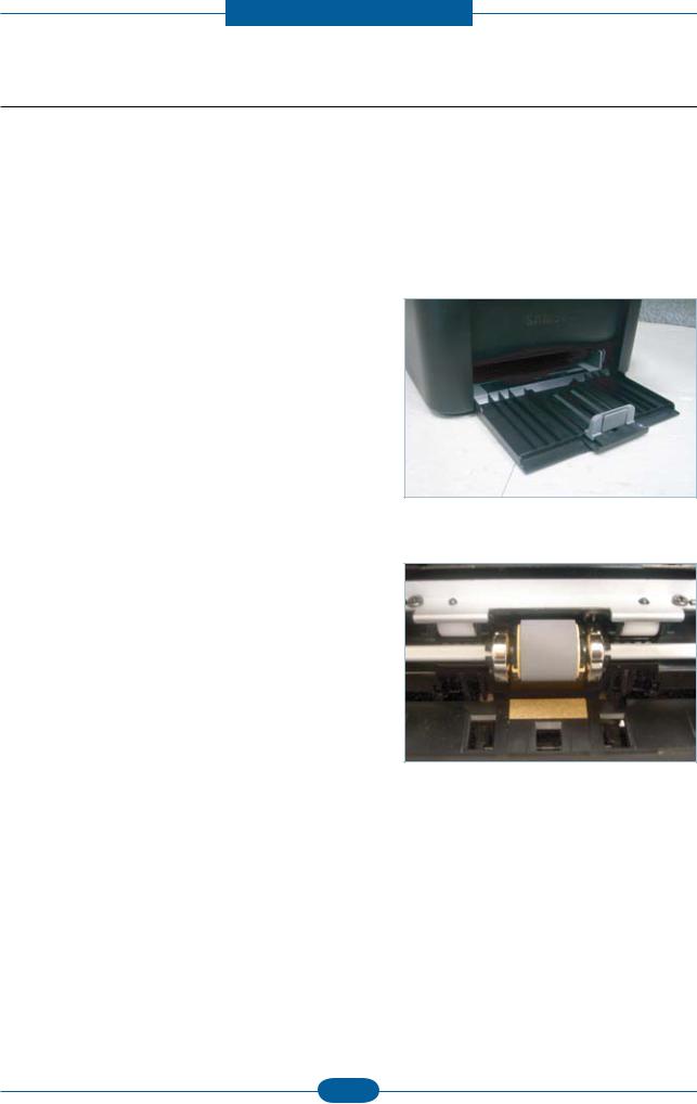
2.2.3.1 Feeding Part
It is consists of a basic cassette, an MP tray for printing on special media (envelope, label, special paper).
1) Separation method
Paper is separated by the friction pad mounted to the center of the cassette.
2) Input tray
This model uses a bin-type tray to hold the paper.
It takes a center loading method and applies ‘friction pad separating method.
Both the side guide and the rear guide can be adjusted for various types of papers from A6 to legal size paper.
The input tray uses a Paper Empty Sensor for paper detection.
(Capacity: 150 sheets (80g/ paper standard), paper arranging function, various size papers accepting function. In the front side, there is a paper level indicator.
3) Pickup roller
The paper feed system is comprised of a paper pickup, driving, control function, paper feeding, and static removal function. The Pick up roller is driven by a solenoid.
|
Service Manual |
2-15 |
Samsung Electronics |
Product spec and feature
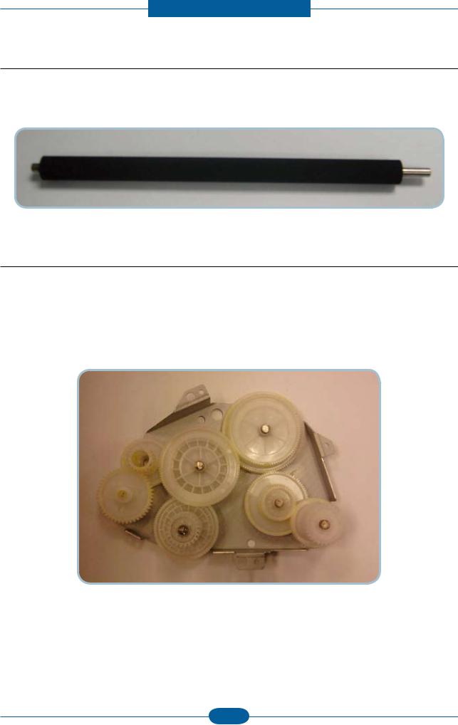
2.2.3.2 Transfer Roller
—The transfer roller delivers the toner from the OPC drum to the paper.
—There is no PTLAss’y.
—Life Span : Print over 30,000 sheets (in15~30 )
2.2.3.3 Driver Assy
—The SCX-3200/3205 Series drive system is comprised of an OPC, Pickup, Feed, Fuser, GearTrain all fixed to as mounting bracket. A step motor is used for driving the assembly; it mounted to the left frame.
•Driving Frequency: Step Motor 840 PPS (1050rpm)
•Drive system is comprised of: Stepping Motor → Pick-up/Feeder/Transfer/Fuser/Exit
|
Service Manual |
2-16 |
Samsung Electronics |

Product spec and feature
2.2.3.4 Fuser
The Fuser Unit consisted of a halogen lamp, heat roller, pressure roller, thermistor and thermostat. It fuses the toner on a paper by a combination of heat and pressure to complete the printing job.
1)Thermostat
When a heat lamp is overheated, a Thermostat cuts off the main power to prevent overheating.
—Thermostat Type : NonContact type dual THERMOSTAT
—Control Temperature : 195 ± 5
2)Thermistor
It is a temperatrue detecting sensor.
—Temperature Resistance : 7 (180 )
Provide spec cold at rook temp
Example: 375K ohms
3)Heat roller
The heat roller transfers the heat from the lamp to apply a heat on the paper.
The surface of a heat roller is coated with Teflon, so toner does not stick to the surface.
4)Pressure roller
A pressure roller mounted under a heat roller is made of a silicon resin, and the surface also is coated with Teflon. When a paper passes between a heat roller and a pressure roller, toner adheres to the surface of a paper permanently.
5)Halogen Lamp
—Voltage 120 V : 115 ± 5 %
220 V : 230 ± 5 %
— Capacity : 600 Watt ± 25 W
|
Service Manual |
2-17 |
Samsung Electronics |

Product spec and feature
6)Items for safety
Protecting device for overheating
—1st protection device: Hardware cuts off when overheated
—2nd protection device: Software cuts off when overheated
—3rd protection device: Thermostat cuts off main power.
Safety device
—The fuser power is cut off when a front cover is opened
—A caution label has been added to the Fuser Unit to warn the customer of the “Hot Area”, so they can use care when in that area. It can be easily seen when customer opens the rear cover.
|
Service Manual |
2-18 |
Samsung Electronics |
Product spec and feature
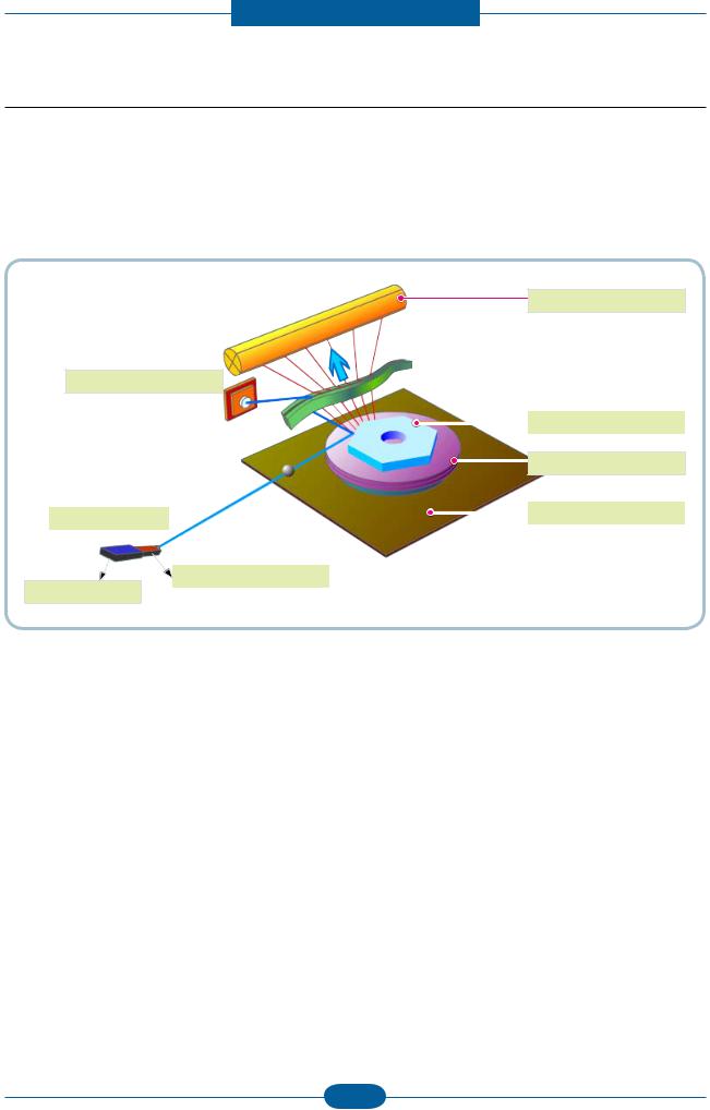
2.2.3.5 LSU (Laser Scanner Unit)
It is the core part of the LBP which switches from the video data received to the controller to the electrostatic latent image on the OPC drum by controlling laser beam, exposing OPC drum, by use of a polygon mirror. The OPC drum is synchronized with the paper feeding speed. The /HSYNC signal is created when the laser beam from LSU reaches the end of the polygon mirror, and the signal is sent to the controller.
The controller detects the /HSYNC signal to adjust the vertical line of the image on paper. The /HSYNC signal is used to synchronize the image data with the left margin of the paper.
OPC Drum
Photo Diode
|
Polygon Mirror |
|||||||||||
|
Polygon Motor |
|||||||||||
|
LD Driver circit |
Motor Driver |
||||||||||
|
LD(Laser Diode) |
|||||||||||
|
Protector panel |
|||||||||||
|
Service Manual |
2-19 |
Samsung Electronics |
Product spec and feature
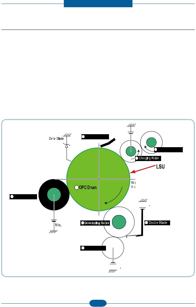
2.2.3.6 Toner Cartridge
By using the electronic photo process, it creates a visual image. In the toner cartridge, the OPC unit and the developing unit are contained in one assembly. The OPC unit houses the OPC drum and charging roller, the toner cartridge unit houses the toner, supply roller, developing roller, and blade (Doctor blade)
•Developing Method : Non magnetic 1 element contacting method
•Toner : Non magnetic 1 element shatter type toner
•Charging capacity : — 39.1 ± 3 μC/g
•Average OD : 8.0 ± 0.5 (Toner)
•The life span of toner (ISO 19752 pattern / Letter standard)
→Initial toner : 0.7K
→Sales toner : 1.5K
•Toner Residual Sensor : Dot count with CRUM(CRU Monitor)
•OPC Cleaning : Collect the toner by using cleaning blade
•Handling of wasted toner : Waste [residual] toner is cleaned off the drum by means of a cleaning blade.
•OPC Drum Protecting Shutter : None
•Classifying device for toner cartridge: ID is classified by CRUM.
|
Max -1.4KV |
|
|
2 |
Cleaning Roller |
|
1 |
|
Service Manual |
2-20 |
Samsung Electronics |
![]()
Product spec and feature
2.2.4 Engine H/W Specifications
2.2.4.1 Main PBA
The Engine and the Printer Controller function are housed into one Main Board called Main PBA. The CPU is functioned as the bus control, I/O handling, drivers, and PC interface. The main board sends the Current Image of Video data to the LSU and manages the conduct of manages the electrophotography for printing. The CPU on Main PBA manages the circuits for the motors: paper feed, paper path, clutches, pretransfer lamp, current control to driver components, and fan driving.
The signals from the paper feed jam sensor and paper empty sensor are directly inputted to the main board.
|
CN15. WLAN |
|||||
|
(wireless only) |
|||||
|
CN10. |
CN7. |
CN14. |
|||
|
FLAT |
CN12. |
CN5. |
|||
|
CN9. PICK |
FUSER |
MOTOR |
LSU |
SENSOR |
OPE |
|
UP_CLUTCH |
CN11. |
||||
|
OUTBIN |
|||||
|
CN17. |
FULL |
||||
|
FAN |
CN8. |
||||
|
CN2. |
CIS |
||||
|
MAIN |
|||||
|
MOTOR |
CN16. |
||||
|
CN6. |
USB |
||||
|
POWER |
|||||
|
I/F |
|||||
|
CN1. |
CN4. WIERED LAN |
||||
|
(wireless only) |
|||||
|
HYPER |
|||||
|
Service Manual |
2-21 |
Samsung Electronics |

Product spec and feature
(a) ASIC (Jupiter5)
—CPU Core : Use 32 Bit RISC Processor of Jupiter5 which uses ARM 926EJS core.
—the main function of ASIC has the following feautres;
-> Multi-layered bus architecture for bus traffic distribution -> Multi-Port DDR SDRAM Controller
-> external NOR flash controller and SPI interface, which Supports Auto Boot operation using external Serial Flash.
-> Speed
—Up to 133MHz Bus Interface and DRAM interface
—GDI Mono MFP: up to 30 ppm at 2400 dpi mode
—Supports A4 paper size
(b) Memory
1)Serial-type nor flash memory
Store System Program and can be download System Program through PC Interface
— Capacity : 4MByte(SCX-3200/3205), 8MByte(SCX-3205W)
2)DDR2 SDRAM
When Printing, use Band Buffer, System Working Memory Area.
— Capacity : 32M Byte (SCX-3200/3205) 128M Byte (SCX-3205W)
for printing System Working Memory Area
|
Service Manual |
2-22 |
Samsung Electronics |

Product spec and feature
(c) Sensor Input Circuit
■ Paper Empty Sensing
The Paper empty sensor on the tray detects the state of paper empty and the state of paper width i.e. narrow paper width or not.
■ Regi Sensing
N/A
■ Paper Feeding
When paper passes the actuator (feed sensor part), it detects the signal by use of a Photo interrupter, informs the CPU, and synchronizes the image data after a predetermined time.
If it doesn’t detect the feed sensor within 1sec. after paper is fed, paper Jam0 is occurred (LED will be display Orange color).
■ Paper Exit Sensing
N/A
■ Cover Open Sensing
The Cover open sensor is located on the HVPS. After the top cover is opened, +24VS (Solenoid, Main Motor, Polygon motor part of LSU and HVPS), which is supplied to the each unit, is cut off.
In case, the red light will will be ON to inform the end-user.
■ SOLENOID Driving
The clutches are driven by turning on the TRs, which is controlled by the CPU. The diode in the Clutch driving circuits protects TR driven from the noise, which may occur when the solenoid is de-energized.
■ Motor Driving
The main motor driving circuits is on the main board
There is motor driver IC on the main board, to control the step motor.
|
Service Manual |
2-23 |
Samsung Electronics |

Product spec and feature
2.2.4.2 HVPS and SMPS Board
The HVPS Board and SMPS Board housed in one board.
The HVPS board creates the high voltage of THV/MHV/Supply/Dev and supplies it to the developer portion, so as to develop the optimum image quality. The HVPS portion takes the 24V and outputs the high voltage for THV/MHV/BIAS, and supplied to the high voltage, OPC cartridge, and transfer roller for optimum latent image and toner transfer quality.
It is the power source of entire system. It is assembled by an independent module, so it is possible to use for common use. It is mounted on the side of the machine.
It is consisted of the SMPS portion, which supplies the DC power for driving the system, and AC to power the Fuser Unit. SMPS has two output channels, which are +3.3V and +24V.
Main Board
Fuser
|
Service Manual |
2-24 |
Samsung Electronics |

Product spec and feature
■ HVPS Board
• Transfer High Voltage (THV+)
—Input Voltage : 24 V DC ± 15%
—Output Voltage : THV+: max +3.5kV ± 10 %,(Duty Variable, no loading ) THV-: -1kV±20% (when cleaning,200 )
—Input contrast of the Voltage stability degree : under ± 3 % (fluctuating input 21.6V~26.4V)
Loading contrast : ± 3 % or less
—Output Voltage Rising Time : 50 ms Max
—Output Voltage Falling Time : 100 ms Max
—Fluctuating transfer voltage with environmental various : 0~3.5kV
—Environment Recognition Control Method : The THV-PWM ACTIVE is transfer active signal. It detects the resistance by recognizing the voltage value, F/B, while permits the environmental recognition voltage.
—Output Voltage Control Method : Transfer Output Voltage is outputted and controlled by changing Duty of THVPWM Signal.
• Charge Voltage (MHV)
— Input Voltage : 24 V DC ± 15%
— Output Voltage : -1.0KV ~ -1.8KV DC ± 3% — Output Voltage Rising Time : 50 ms Max — Output Voltage Falling Time : 50 ms Max — Output Loading range : 30 MΩ ~ 1000 MΩ
— Output Control Signal(MHV-PWM) : CPU is HV output when PWM is Low
• Cleaning Voltage (THV- )
— The (+) Transfer Voltage is not outputted because the THV PWM is controlled with low.
— The (-) Transfer Voltage is outputted because the THV-Enable Signal is controlled with low — The output fluctuation range is big because there is no Feedback control.
• Developing Voltage (DEV)
—Input Voltage : 24 V DC ± 15%
—Output Voltage: -200V ~ -500V DC ±3%
—Output Voltage Fluctuation range: PWM Control
—Input contrast of the output stability degree : ± 3 % or less Loading contrast : ± 3 % or less
—Output Voltage Rising Time : 50 ms Max
—Output Voltage Falling Time : 50 ms Max
—Output Loading range : 10MΩ ~ 1000 MΩ
—Output Control Signal (BIAS-PWM) : the CPU output is HV output when PWM is low.
• Supply
—Output Voltage : -350 V ~ -650V DC ±50 V(ZENER using, DEV )
—Input contrast of the output stability degree : under ± 5 %
Loading contrast : ± 5 % or less
—Output Voltage Rising Time : 50 ms Max
—Output Voltage Falling Time : 50 ms Max
—Output Loading range : 10 MΩ ~ 1000 MΩ
—Output Control Signal (BIAS-PWM) : the CPU is HV output when PWM is low.
|
Service Manual |
2-25 |
Samsung Electronics |

Product spec and feature
■ SMPS Board
|
• AC Input |
|
|
— Input Rated Voltage : AC 220V ~ 240V AC 110V |
~ 127V |
|
— Input Voltage fluctuating range : AC 180V ~ 270V |
AC 90V ~ 135V |
—Rated Frequency : 50/60 Hz
—Frequency Fluctuating range : 47 ~ 63 Hz
—Input Current : Under 4.0Amps / 2.0Amps (But, the status when Fuser is off or rated voltage is inputted/ outputted
• Rated Output Power
|
NO |
ITEM |
CH1 |
CH2 |
Remark |
|
1 |
CHANNEL NAME |
+3.3V |
+24.0V |
|
|
CON 3 |
CON 3 |
|||
|
2 |
CONNECTOR PIN |
3.3V PIN: 5,7 |
24V PIN:1,2,3 |
|
|
GND PIN: 8,9 |
GND PIN:8,9,25,26 |
|||
|
3 |
Rated Output |
+3.3V±5% |
+24V±10% -> -10%, +15%, |
|
|
(3.135~3.465V) |
(21.6~26.4V) -> 27.6V |
|||
|
4 |
Max. Output Current |
0.8A |
1.35A |
|
|
5 |
Peak Loading Current |
1.0A |
1.8A |
100ms |
|
6 |
RIPPLE NOISE Voltage |
100mVp-p |
Under 500mVp-p |
|
|
7 |
Maximum output |
2.64W |
32.4W |
|
|
8 |
Peak output |
3.3W |
43.2W |
100ms |
|
9 |
Protection for loading shortage |
Shut down or Fuse |
Shut down or Output |
|
|
and overflowing current |
Protection |
Voltage Drop |
||
|
Service Manual |
2-26 |
Samsung Electronics |

Product spec and feature
2.2.5 Engine F/W Contol Algorithm
2.2.5.1 Feeding
If feeding from a cassette, drive of the pickup roller is controlled by a solenoid. The on/off of the solenoid is controlled by controlling the general output port or the external output port. Provided below are the units jam conditions:
—After picking up, paper is not fed.
—After picking up, paper entered but it cannot reach to the feed sensor in a predetermined
time due to slippage, etc.
JAM 0 — After picking up, if the feed sensor is not on, re-pick up. After re-picking up, if the feed sensor is still not on after a predetermined time, JAM 0 is displayed.
*It is a status that the leading edge of the paper doesn’t pass the feed sensor.
—Even though the paper reaches to the feed sensor, the feed sensor doesn’t be ON.
*It is a status that the leading edge of the paper already passes the feed sensor.
|
JAM 1 |
— After the leading edge of the paper passes the feed sensor, the trailing edge of the paper |
|
|
must clear the sensor within a predetermined time. (The feed sensor cannot be OFF) |
||
2.2.5.2 Transfer
The charging, developing and the transfer voltages. are controlled by PWM (Pulse Width Modulation). Each output voltage is changeable due to the PWM duty. The transfer voltage admitted when the paper passes the transfer roller is decided by environment conditions. The resistance value of the transfer roller is changed due to the surrounding environment ; the voltage values change to compensate for the environmental conditions. It is managed through an AD converter. The voltage value for the transfer roller is decided by the changed value.
|
Service Manual |
2-27 |
Samsung Electronics |

Product spec and feature
2.2.5.3 Fusing
The temperature change of the heat roller’s surface is changed to the resistance value through the thermistor. The Heat Roller temperate (warmup) is measured by converting the resistance of the thermistor to a measurable DC voltage value. The AD converter changes it to a digital value so it knows when it has reach its proper fusing temperature. The AC power to the fuser lamp is controller by comparing the target temperature to the value from the thermistor. If the value from the thermistor is out of controlling range an error will occur and power disabled. Each Heading below lists the types of Fuser Errors that can occur:
• Open Heat Error
During warmup, if the Fuser Unit does not reach its proper operating temperature within a predetermined time an “Open Heat Error will occur. An error message will be displayed on the Control Panel alerting the customer. The engine stops all functions and keeps it at the error state until the issue is resoled by a qualified technician.
• Low Heat Error
After initial warmup had been achieved, if the Fuser Unit at any time does not reach its proper operating temperature within a predetermined time an “Low Heat Error will occur. An error message will be displayed on the Control Panel alerting the customer. The engine stops all functions and keeps it at the error state until the issue is resoled by a qualified technician.
• Over Heat Error
If the Fuser Unit at any time exceeds the specified range [too hot] for proper operating temperature an “Over Heat Error will occur. An error message will be displayed on the Control Panel alerting the customer. The engine stops all functions and keeps it at the error state until the issue is resoled by a qualified technician.
2.2.5.4 LSU
LSU receives the image data from PVC or HPVC and makes the latent image on OPC surface. It uses the single beam, LD.
The errors related to LSU are as follows:
•By LReady : When the printing is started, the engine drives the polygon motor of LSU. After the specified time is elapsed, if the motor is not in a ready status, the engine detects the error that the polygon motor is not in a ready status. If this error happens, the engine stops all functions and keeps it at the error state. Also, the engine informs the error status of the main system and the error message is displayed at LCD window to inform the error status to the customer.
•By Hsync : When the polygon motor is ready, the LSU sends out the signal called Hsync and it is used to synchronize with each image line. So, if the engine does not detect consecutively the signal for a fixed time, it defines the Hsync Error. If this error happens, the engine stops all functions and keeps it at the error state. Also, the engine informs the error status of the main system and then the error message is displayed at LCD window to inform the error status to the customer.
LSU Error Recovery: If the LReady or Hsync error happens, the paper is exited with no image on it. The engine mode is changed to recovery mode and the engine informs the main system of the engine mode. And the engine checks the LSU error. If the error doesn’t happen, the printing job will be proceeding.
|
Service Manual |
2-28 |
Samsung Electronics |

Product spec and feature
2.2.6 S/W Descriptions
2.2.6.1 Overview
The software of SCX-3200/3205 Series system is constructed as follows:
1)The Host Software is an application software that can operate in a Windows and/or Web Environment.
2)The Firmware portion is an Embedded software controlling the print job.
2.2.6.2 Architecture
|
HOST Software |
Firmware |
|||||||||||||||||||||||||
Host Software is made up of:
1.Graphic User Interface that offers the various editing functions to user.
2.Driver that translates the received document to a Printing Command Language which printer can understand and transfers data to spooler.
3.Stand-alone Application that offers the various printing application, PSU(Printer Settings Utility), Printer Status Monitor, Network Management in Window system.
4.Web-based-Application that offers the same functions as Stand-alone Application and RDC(Remote Diagnosis Control) in Web environment.
Firmware is made up of:
1.Application (Emulation) that is a interpreter translate data received from Host to a printing language (PCL, PS, GDI, etc.) to be able to allow the user to take same output as original composed in Host.
2.Kernel that control and management the whole procedure include of Control flow and Printing Job before transfer to Engine system.
|
Service Manual |
2-29 |
Samsung Electronics |

Product spec and feature
2.2.6.3 Data and Control Flow
—SPL, PCL5e
—Document Management System
—Network Administration
—Status Monitor
—Remote Control Panel
—Printer Settings Utility
—Network Administration
—Status Monitor
Application (Emulation)
—PCL
—PostScript
—etc
Provided below is a detail explanation of the Block Diagram above.
Host Side is made up of:
1.The Print Driver that is Windows application software translates printed data to one of printer languages and creates spooler file.
2.Web-based Application offer a varity of additional functions for the printer; management of printing job, printer administration, Status monitor to monitoring the printer status by real time in Web, independent environment on OS.
3.Stand-alone Application that is a similar Window software as same as above 2,
4.Port Monitor that manages the network communication between spooler and Network Interface Card, or various additional application and Network Interface Card,(this is, at first, make communication logical port, manage the data, transfer them from spooler to network port, and offer the result of printing).
|
Service Manual |
2-30 |
Samsung Electronics |
![]()
Product spec and feature
Firmware Side is made up of:
1.Network Interface Card is that relay the communication between Host and kernel using various network protocols.
2.Kernel manages the flow control of emulation procedure, receiving data from the Host or Network card and printing with engine & rendering job.
3.Emulation interprets the various output data from selected emulation.
4.Engine prints rendered bit-map data to paper with required size and type by Kernel.
The Job Spooling function for Multi-User, Multi-Printing that is occurred in Network printing and various additional printing functions, this Kernel use max. 10 Queuing systems in a memory.
In Printing, the two procedures are:
(1)Case of using USB Port
—After user start to print their document to PCL string or compressed GDI bit-map data; the driver translates the all graphic data and send the data to host spooler. And then the spooler sends the data stream to the printer via USB port.
—Kernel receives this data from the Host, and then selects the emulation fit to data and start selected one. After emulation job ends Kernel sends the output bit-map data to Engine using Printer Video Controller (by clock type for LSU).
—Engine print the received data to required paper with the sequential developing process.
(2)Network Interface Card
—After the user starts to print their document to PCL string or compressed GDI bit-map data, Driver translate the all graphic data of it and send data to host spooler.
—If so, Port monitor managing network port receives data from spooler and sends a data stream to the Network Interface Card.
—Network interface card receives it and send to Kernel part.
—Kernel receives this data from Host, and selects emulation fit to data and start selected one. After emulation job ends Kernel sends the output bit-map data to the Engine using Printer Video Controller (by clock type for LSU).
—Engine print the received data to required paper with the sequential developing process.
The additional printing function are realized in:
(1)Web environment.
(2)Window environment.
On addition, Kernel informs the printing and printer status to end-user made printing job with the Status Monitor.
|
Service Manual |
2-31 |
Samsung Electronics |

Disassembly and Reassembly
3. Disassembly and Reassembly
3.1 Precautions when replacing parts
3.1.1 Precautions when assembling and disassembling
*Use only approved Samsung spare parts. Ensure that part number, product name, any voltage, current or temperature rating are correct. Failure to do so could result in damage to the machine, circuit overload, fire or electric shock.
*Do not make any unauthorized changes or additions to the printer, these could cause the printer to malfunction and create electric shock or fire hazards.
*Take care when dismantling the unit to note where each screw goes. There are 19 different screws. Use of the wrong screw could lead to system failure, short circuit or electric shock.
*Do not disassemble the LSU unit. Once it is disassembled dust is admitted to the mirror chamber and will seriously degrade print quality. There are no serviceable parts inside.
*Regularly check the condition of the power cord, plug and socket. Bad contacts could lead to overheating and firfe. Damaged cables could lead to electric shock or unit malfunction.
3.1.2 Preautions when handling PBA
Static electricity can damage a PBA, always used approved anti-static precautions when handling or storing a PBA.
>> Precautions when moving and storing PBA
1. Please keep PBA in a conductive case, anti-static bag, or wrapped in aluminum foil. 2. Do not store a PBA where it is exposed to direct sunlight.
>> Precautions when replacing PBA
1. Disconnect power connectors first, before disconnecting other cables
2. Do not touch any soldered connections, connector terminals or other electronic parts when handling insulated parts.
>> Precautions when checking PBA
1.Before touching a PBA, please touch other grounded areas of the chassis to discharge any static electrical charge on the body.
2.Take care not to touch the PBA with your bare hands or metal objects as you could create a short circuit or get an electric shock. Take extra care when handling PBAs with moving parts fitted such as sensors, motors or lamps as they may get hot.
3.Take care when fitting, or removing, screws. Look out for hidden screws. Always ensure that the correct screw is used and always ensure that when toothed washers are removed they are refitted in their original positions.
3.1.3 Releasing Plastic Latches
Many of the parts are held in place with plastic latches. The latches break easily; release them carefully.
To remove such parts, press the hook end of the latch away from the part to which it is latched.
|
Service Manual |
3-1 |
Samsung Electronics |
 Loading…