
- Лазерная резка
- Машины плазменной резки
- Источники для резки с ЧПУ
- Расходные материалы
- Программное обеспечение
Инструкция по эксплуатации системы плазменно-дуговой резки Powermax 105. Инструкция содержит все важные сведения для эффективной и безопасной работы с системой, включая информацию об установке, методах снижения излучения, уравнивании потенциалов и настройке источника тока и др.
![]() Powermax 105 инструкция по эксплуатации
Powermax 105 инструкция по эксплуатации
Популярные товары
-

Steel Tailor Power
Портативные системы -
Установка термической резки труб Steel Tailor Tube I
Машины для резки труб -
Powermax 125
Установки для ручной резки -
Powermax105 SYNC
Установки для ручной резки -
Машина плазменной резки Sapphire
Машины плазменной резки -
MAXPRO200
Установки для ручной резки -
HASA CS-3 Unlimited
Машины плазменной резки -
Станок для резки труб с ЧПУ TubeTailor II
Машины для резки труб -
Legacy XP
Портативные системы -
Powermax 105
Установки для ручной резки -
Машина плазменной резки Jantar
Машины плазменной резки -
Плазменная машина термической резки HASA
Машины плазменной резки -
CS-3 Essential
Машины плазменной резки -
Uppercut
Установки для ручной резки


<
>
Наши преимущества
![]()
![]()
Шоу-рум
Представлено оборудование в различных ценовых сегментах и с разными конструктивными
особенностями
![]()
Тест-драйв
Возможность познакомиться с технологией резки, собственноручно протестировав
интересующую Вас модель оборудования
![]()
![]()
Гарантия качества
Мы поставляем только качественный, оригинальный и сертифицированный товар
![]()
Лизинговые программы
Позволят привлечь внешнее финансировать и получить значительные финансовые льготы для
Вашего предприятия
![]()
Монтаж оборудования
Монтаж станков и ввод их в эксплуатацию — гарантия бесперебойной работы
оборудования
![]()
Надежный сервис
Авторизованный сервисный персонал компании обеспечит оперативный отклик на Ваше
обращение
![]()
Plasma arc cutting systems
Service Manual – 807580
Revision 1

Plasma arc cutting systems
Service Manual – 807580
Revision 1

Register your new Hypertherm system
Register your product on-line at www.hypertherm.com/registration for
easier technical and warranty support. You can also receive updates on new
Hypertherm products and a free gift as a token of our appreciation.
For your records
Serial number: _____________________________________________
Purchase date: _____________________________________________
Distributor: _____________________________________________
________________________________________________________
________________________________________________________
Maintenance notes:
____________________________________________________________
____________________________________________________________
____________________________________________________________
____________________________________________________________
____________________________________________________________
____________________________________________________________

Service Manual
(P/N 807580)
Revision 1 – November 2013
Hypertherm, Inc.
Hanover, NH USA
www.hypertherm.com
email: info@hypertherm.com
© Copyright 2013 Hypertherm, Inc.
All Rights Reserved
Hypertherm and Powermax are trademarks of Hypertherm, Inc.
and may be registered in the United States and/or other countries.
powermax
105

Hypertherm Inc.
Etna Road, P.O. Box 5010
Hanover, NH 03755 USA
603-643-3441 Tel (Main Office)
603-643-5352 Fax (All Departments)
info@hypertherm.com (Main Office Email)
800-643-9878 Tel (Technical Service)
technical.service@hypertherm.com (Technical Service Email)
800-737-2978 Tel (Customer Service)
customer.service@hypertherm.com (Customer Service Email)
866-643-7711 Tel (Return Materials Authorization)
877-371-2876 Fax (Return Materials Authorization)
return.materials@hypertherm.com (RMA email)
Hypertherm Plasmatechnik GmbH
Technologiepark Hanau
Rodenbacher Chaussee 6
D-63457 Hanau-Wolfgang, Deutschland
49 6181 58 2100 Tel
49 6181 58 2134 Fax
49 6181 58 2123 (Technical Service)
Hypertherm (S) Pte Ltd.
82 Genting Lane
Media Centre
Annexe Block #A01-01
Singapore 349567, Republic of Singapore
65 6841 2489 Tel
65 6841 2490 Fax
65 6841 2489 (Technical Service)
Hypertherm (Shanghai) Trading Co., Ltd.
Unit 301, South Building
495 ShangZhong Road
Shanghai, 200231
PR China
86-21-60740003 Tel
86-21-60740393 Fax
Hypertherm Europe B.V.
Vaartveld 9
4704 SE
Roosendaal, Nederland
31 165 596907 Tel
31 165 596901 Fax
31 165 596908 Tel (Marketing)
31 165 596900 Tel (Technical Service)
00 800 4973 7843 Tel (Technical Service)
Hypertherm Japan Ltd.
Level 9, Edobori Center Building
2-1-1 Edobori, Nishi-ku
Osaka 550-0002 Japan
81 6 6225 1183 Tel
81 6 6225 1184 Fax
Hypertherm Brasil Ltda.
Rua Bras Cubas, 231 – Jardim Maia
Guarulhos, SP — Brasil
CEP 07115-030
55 11 2409 2636 Tel
55 11 2408 0462 Fax
Hypertherm México, S.A. de C.V.
Avenida Toluca No. 444, Anexo 1,
Colonia Olivar de los Padres
Delegación Álvaro Obregón
México, D.F. C.P. 01780
52 55 5681 8109 Tel
52 55 5683 2127 Fax
Hypertherm Korea Branch
#3904 Centum Leaders Mark B/D,
1514 Woo-dong, Haeundae-gu, Busan
Korea, 612-889
82 51 747 0358 Tel
82 51 701 0358 Fax
12/2/13

Compliance Information EMC-1
7/ 10
ELECTROMAGNETIC COMPATIBILITY EMC
Introduction
Hypertherm’s CE-marked equipment is built in compliance
with standard EN60974-10. The equipment should be
installed and used in accordance with the information
below to achieve electromagnetic compatibility.
The limits required by EN60974-10 may not be adequate
to completely eliminate interference when the affected
equipment is in close proximity or has a high degree of
sensitivity. In such cases it may be necessary to use other
measures to further reduce interference.
This cutting equipment is designed for use only in an
industrial environment.
Installation and use
The user is responsible for installing and using the plasma
equipment according to the manufacturer’s instructions.
If electromagnetic disturbances are detected then it shall
be the responsibility of the user to resolve the situation
with the technical assistance of the manufacturer. In some
cases this remedial action may be as simple as earthing
the cutting circuit, see Earthing of the workpiece. In other
cases, it could involve constructing an electromagnetic
screen enclosing the power source and the work
complete with associated input filters. In all cases,
electromagnetic disturbances must be reduced to the
point where they are no longer troublesome.
Assessment of area
Before installing the equipment, the user shall make an
assessment of potential electromagnetic problems in
the surrounding area. The following shall be taken into
account:
a. Other supply cables, control cables, signaling and
telephone cables; above, below and adjacent to the
cutting equipment.
b. Radio and television transmitters and receivers.
c. Computer and other control equipment.
d. Safety critical equipment, for example guarding
ofindustrial equipment.
e. Health of the people around, for example the use
ofpacemakers and hearing aids.
f. Equipment used for calibration or measurement.
g. Immunity of other equipment in the environment. User
shall ensure that other equipment being used in the
environment is compatible. This may require additional
protection measures.
h. Time of day that cutting or other activities are to be
carried out.
The size of the surrounding area to be considered
will depend on the structure of the building and other
activities that are taking place. The surrounding area may
extend beyond the boundaries of the premises.
Methods of reducing emissions
Mains supply
Cutting equipment must be connected to the mains
supply according to the manufacturer’s recommendations.
If interference occurs, it may be necessary to take
additional precautions such as filtering of the mains
supply.

EMC-2 Compliance Information
7/ 10
ELECTROMAGNETIC COMPATIBILITY
Consideration should be given to shielding the supply
cable of permanently installed cutting equipment,
in metallic conduit or equivalent. Shielding should
be electrically continuous throughout its length. The
shielding should be connected to the cutting mains
supply so that good electrical contact is maintained
between the conduit and the cutting power source
enclosure.
Maintenance of cutting equipment
The cutting equipment must be routinely maintained
according to the manufacturer’s recommendations. All
access and service doors and covers should be closed
and properly fastened when the cutting equipment is in
operation. The cutting equipment should not be modified
in any way, except as set forth in and in accordance with
the manufacturer’s written instructions. For example,
the spark gaps of arc striking and stabilizing devices
should be adjusted and maintained according to the
manufacturer’s recommendations.
Cutting cables
The cutting cables should be kept as short as possible
and should be positioned close together, running at or
close to the floor level.
Equipotential bonding
Bonding of all metallic components in the cutting
installation and adjacent to it should be considered.
However, metallic components bonded to the workpiece
will increase the risk that the operator could receive a
shock by touching these metallic components and the
electrode (nozzle for laser heads) at the same time.
The operator should be insulated from all such bonded
metallic components.
Earthing of the workpiece
Where the workpiece is not bonded to earth for
electrical safety, nor connected to earth because of its
size and position, for example, ship’s hull or building
steel work, a connection bonding the workpiece to earth
may reduce emissions in some, but not all instances.
Care should be taken to prevent the earthing of the
workpiece increasing the risk of injury to users, or
damage to other electrical equipment. Where necessary,
the connection of the workpiece to earth should be
made by a direct connection to the workpiece, but
in some countries where direct connection is not
permitted, the bonding should be achieved by suitable
capacitances selected according to national regulations.
Note: The cutting circuit may or may not be earthed for
safety reasons. Changing the earthing arrangements
should only be authorized by a person who is competent
to assess whether the changes will in crease the risk of
injury, for example, by allowing parallel cutting current
return paths which may damage the earth circuits
of other equipment. Further guidance is provided
in IEC60974-9, Arc Welding Equip ment, Part 9:
Installation and Use.
Screening and shielding
Selective screening and shielding of other cables
and equipment in the surrounding area may alleviate
problems of interference. Screening of the entire plasma
cutting installation may be considered for special
applications.

Compliance Information W-1
9/10
Attention
Genuine Hypertherm parts are the factory-
recommended replacement parts for your Hypertherm
system. Any damage or injury caused by the use of other
than genuine Hypertherm parts may not be covered by
the Hypertherm warranty, and will constitute misuse of
the Hypertherm Product.
You are solely responsible for the safe use of the
Product. Hypertherm does not and cannot make any
guarantee or warranty regarding the safe use of the
product in your environment.
General
Hypertherm, Inc. warrants that its Products shall be
free from defects in materials and workmanship for the
specific periods of time set forth herein and as follows: if
Hypertherm is notified of a defect (i)with respect to the
plasma power supply within a period of two (2) years
from the date of its delivery to you, with the exception of
Powermax brand power supplies, which shall be within
a period of three (3) years from the date of delivery
to you, and (ii)with respect to the torch and leads
within a period of one (1) year from its date of delivery
to you, and with respect to torch lifter assemblies
within a period of one (1) year from its date of delivery
to you, and with respect to Automation products
one (1) year from its date of delivery to you, with the
exception of the EDGEProCNC, EDGEProTiCNC,
MicroEDGEProCNC and ArcGlideTHC, which shall
be within a period of two (2) years from the date of
delivery to you, and (iii)with respect to HyIntensity fiber
laser components within a period of two (2) years from
the date of its delivery to you, with the exception of laser
heads and beam delivery cables, which shall be within a
period of one (1) year from its date of delivery to you.
This warranty shall not apply to any Powermax brand
power supplies that have been used with phase
converters. In addition, Hypertherm does not warranty
systems that have been damaged as a result of poor
power quality, whether from phase converters or
incoming line power. This warranty shall not apply to any
product which has been incorrectly installed, modified,
or otherwise damaged.
Hypertherm provides repair, replacement or adjustment
of the Product as the sole and exclusive remedy, if
and only if the warranty set forth herein properly is
invoked and applies. Hypertherm, at its sole option,
shall repair, replace, or adjust, free of charge, any
defective Products covered by this warranty which
shall be returned with Hypertherm’s prior authorization
(which shall not be unreasonably withheld), properly
packed, to Hypertherm’s place of business in Hanover,
New Hampshire, or to an authorized Hypertherm repair
facility, all costs, insurance and freight pre paid by the
customer. Hypertherm shall not be liable for any repairs,
replacement, or adjustments of Products covered by this
warranty, except those made pursuant to this paragraph
and with Hypertherm’s prior written consent.
The warranty set forth above is exclusive and is in
lieu of all other warranties, express, implied, statutory,
or otherwise with respect to the Products or as to
the results which may be obtained therefrom, and
all implied warranties or conditions of quality or of
merchantability or fitness for a particular purpose or
against infringement. The foregoing shall constitute the
sole and exclusive remedy for any breach by Hypertherm
of its warranty.
Distributors/OEMs may offer different or additional
warranties, but Distributors/OEMs are not authorized
togive any additional warranty protection to you or make
any representation to you purporting to be binding upon
Hypertherm.
WARRANTY

W-2 Compliance Information
9/10
WARRANTY
Patent indemnity
Except only in cases of products not manufactured by
Hypertherm or manufactured by a person other than
Hypertherm not in strict conformity with Hypertherm’s
specifications and in cases of designs, processes,
formulae, or combinations not developed or purported
to be developed by Hypertherm, Hypertherm will have
the right to defend or settle, at its own expense, any
suit or proceeding brought against you alleging that
the use of the Hypertherm product, alone and not in
combination with any other product not supplied by
Hypertherm, infringes any patent of any third party. You
shall notify Hypertherm promptly upon learning of any
action or threatened action in connection with any such
alleged infringement (and in any event no longer than
fourteen (14) days after learning of any action or threat
of action), and Hypertherm’s obligation to defend shall
be conditioned upon Hypertherm’s sole control of, and
the indemnified party’s cooperation and assistance in,
the defense of the claim.
Limitation of liability
In no event shall Hypertherm be liable to any
person or entity for any incidental, consequential
direct, indirect, punitive or exemplary damages
(including but not limited to lost profits)
regardless of whether such liability is based on
breach of contract, tort, strict liability, breach
of warranty, failure of essential purpose, or
otherwise, and even if advised of the possibility
of such damages.
National and local codes
National and local codes governing plumbing and
electrical installation shall take precedence over any
instructions contained in this manual. In no event shall
Hypertherm be liable for injury to persons or property
damage by reason of any code violation or poor work
practices.
Liability cap
In no event shall Hypertherm’s liability, if any,
whether such liability is based on breach of
contract, tort, strict liability, breach of warranties,
failure of essential purpose or otherwise, for
any claim, action, suit or proceeding (whether
in court, arbitration, regulatory proceeding or
otherwise) arising out of or relating to the use of
the Products exceed in the aggregate the amount
paid for the Products that gave rise to such claim.
Insurance
At all times you will have and maintain insurance in such
quantities and types, and with coverage sufficient and
appropriate to defend and to hold Hypertherm harmless
in the event of any cause of action arising from the use
of the products.
Transfer of rights
You may transfer any remaining rights you may have
hereunder only in connection with the sale of all or
substantially all of your assets or capital stock to a
successor in interest who agrees to be bound by all of
the terms and conditions of this Warranty. Within thirty
(30) days before any such transfer occurs, you agree to
notify in writing Hypertherm, which reserves the right of
approval. Should you fail timely to notify Hypertherm and
seek its approval as set forth herein, the Warranty set
forth herein shall be null and void and you will have no
further recourse against Hypertherm under the Warranty
or otherwise.

powermax
105
Service Manual
v
Safety information
Before operating any Hypertherm equipment, read the separate Safety and Compliance Manual (80669C) included
with your product for important safety information.

vi powermax
105
Service Manual

Table of ConTenTs
powermax
105
Service Manual
vii
Section 1
Specifications
Safety information …………………………………………………………………………………………………………………………………………………………….. 1-2
System description …………………………………………………………………………………………………………………………………………………………… 1-2
Where to find information …………………………………………………………………………………………………………………………………………………1-3
Power supply dimensions ………………………………………………………………………………………………………………………………………………… 1-4
Component weights (105 A systems) …………………………………………………………………………………………………………………………….. 1-5
Powermax105 power supply ratings ……………………………………………………………………………………………………………………………….. 1-6
Duramax 75° hand torch dimensions ………………………………………………………………………………………………………………………………. 1-8
Duramax 15° hand torch dimensions ………………………………………………………………………………………………………………………………. 1-8
Duramax 180° full-length machine torch dimensions ……………………………………………………………………………………………………… 1-9
Duramax 180° mini machine torch dimensions ……………………………………………………………………………………………………………….. 1-9
Powermax105 cutting specifications ……………………………………………………………………………………………………………………………. 1-10
Symbols and markings …………………………………………………………………………………………………………………………………………………… 1-11
Noise levels ……………………………………………………………………………………………………………………………………………………………………. 1-11
IEC symbols …………………………………………………………………………………………………………………………………………………………………… 1-12
Section 2
Power Supply Setup
Unpack the Powermax system …………………………………………………………………………………………………………………………………………. 2-2
Claims ………………………………………………………………………………………………………………………………………………………………………2-2
Contents ………………………………………………………………………………………………………………………………………………………………….. 2-3
Position the power supply…………………………………………………………………………………………………………………………………………………2-4
Prepare the electrical power …………………………………………………………………………………………………………………………………………….2-4
Install a line-disconnect switch ……………………………………………………………………………………………………………………………….2-5
Requirements for grounding …………………………………………………………………………………………………………………………………… 2-5
Power connection for the Powermax105 ………………………………………………………………………………………………………………………… 2-6
Three-phase power cord and plug installation ………………………………………………………………………………………………………. 2-8
Extension cord recommendations ……………………………………………………………………………………………………………………………………. 2-9
Extension cord specifications …………………………………………………………………………………………………………………………………. 2-9
Engine-driven generator recommendations ………………………………………………………………………………………………………… 2-10
Prepare the gas supply ………………………………………………………………………………………………………………………………………………….. 2-11
Additional gas filtration …………………………………………………………………………………………………………………………………………. 2-11
Connect the gas supply ……………………………………………………………………………………………………………………………………….. 2-12

Table of ConTenTs
viii powermax
105
Service Manual
Section 3
Basic System Operations
Controls and indicators ……………………………………………………………………………………………………………………………………………………. 3-2
Rear controls ……………………………………………………………………………………………………………………………………………………………3-2
Front controls and LEDs …………………………………………………………………………………………………………………………………………. 3-2
Status screen …………………………………………………………………………………………………………………………………………………………..3-4
Operating the Powermax105 …………………………………………………………………………………………………………………………………………… 3-6
Connect the electrical power, gas supply, and torch lead …………………………………………………………………………………….3-6
Attach the work lead to the power supply ……………………………………………………………………………………………………………… 3-7
Attach the work clamp to the workpiece ………………………………………………………………………………………………………………..3-8
Turn ON the system ………………………………………………………………………………………………………………………………………………… 3-9
Set the operating mode switch ………………………………………………………………………………………………………………………………. 3-9
Check the indicators …………………………………………………………………………………………………………………………………………….. 3-10
Manually adjusting the gas pressure ……………………………………………………………………………………………………………………. 3-10
Adjusting the current (amperage) ………………………………………………………………………………………………………………………… 3-11
Electrode end-of-life detection feature …………………………………………………………………………………………………………………………. 3-11
Understanding duty-cycle limitations ……………………………………………………………………………………………………………………………. 3-12
Section 4
Hand Torch Setup
Introduction ……………………………………………………………………………………………………………………………………………………………………….4-2
Consumable life …………………………………………………………………………………………………………………………………………………………………4-2
Hand torch components …………………………………………………………………………………………………………………………………………………..4-3
Choose the hand torch consumables ……………………………………………………………………………………………………………………………… 4-4
Drag-cutting 105 A consumables ………………………………………………………………………………………………………………………….. 4-4
Drag-cutting 45 A, 65 A, 85 A consumables ………………………………………………………………………………………………………… 4-4
Hand torch consumables …………………………………………………………………………………………………………………………………………………. 4-5
Gouging consumables ……………………………………………………………………………………………………………………………………………. 4-5
FineCut
®
consumables …………………………………………………………………………………………………………………………………………… 4-5
Install the hand torch consumables …………………………………………………………………………………………………………………………………. 4-6
Connecting the torch lead ……………………………………………………………………………………………………………………………………………….. 4-7
Section 5
Hand Cutting
Using the hand torch ………………………………………………………………………………………………………………………………………………………… 5-2
Operate the safety trigger ………………………………………………………………………………………………………………………………………………… 5-2
Hand torch cutting hints …………………………………………………………………………………………………………………………………………………… 5-3
Start a cut from the edge of the workpiece …………………………………………………………………………………………………………………….. 5-4
Pierce a workpiece …………………………………………………………………………………………………………………………………………………………… 5-5
Gouge a workpiece ………………………………………………………………………………………………………………………………………………………….. 5-6
Gouge profile …………………………………………………………………………………………………………………………………………………………..5-7
Varying the gouge profile ………………………………………………………………………………………………………………………………………… 5-8
Common hand-cutting faults ……………………………………………………………………………………………………………………………………………. 5-8

Table of ConTenTs
powermax
105
Service Manual
ix
Section 6
Machine Torch Setup
Introduction ……………………………………………………………………………………………………………………………………………………………………….6-3
Consumable life …………………………………………………………………………………………………………………………………………………………………6-3
Machine torch components ……………………………………………………………………………………………………………………………………………… 6-4
Converting a full-length machine torch to a mini machine torch …………………………………………………………………………………….6-5
Mount the torch ………………………………………………………………………………………………………………………………………………………………… 6-7
Choose the machine torch consumables …………………………………………………………………………………………………………………………6-9
Machine torch consumables …………………………………………………………………………………………………………………………………………….6-9
Mechanized shielded 105 A consumables …………………………………………………………………………………………………………….6-9
Mechanized shielded 45 A, 65 A, 85 A consumables …………………………………………………………………………………………..6-9
Mechanized shielded with ohmic 105 A consumables ………………………………………………………………………………………. 6-10
Mechanized shielded with ohmic 45 A, 65 A, 85 A consumables …………………………………………………………………….. 6-10
Mechanized unshielded 105 A consumables ……………………………………………………………………………………………………… 6-10
Mechanized unshielded 45 A, 65 A, 85 A consumables ……………………………………………………………………………………. 6-10
Gouging consumables …………………………………………………………………………………………………………………………………………. 6-11
FineCut
®
shielded consumables …………………………………………………………………………………………………………………………. 6-11
FineCut
®
unshielded consumables …………………………………………………………………………………………………………………….. 6-11
Install the machine torch consumables …………………………………………………………………………………………………………………………. 6-12
Aligning the torch …………………………………………………………………………………………………………………………………………………………… 6-12
Connecting the torch lead …………………………………………………………………………………………………………………………………………….. 6-13
Using the cut charts ………………………………………………………………………………………………………………………………………………………. 6-14
Estimated kerf-width compensation …………………………………………………………………………………………………………………….. 6-15
105 A Shielded consumables ……………………………………………………………………………………………………………………………… 6-17
105 A Shielded cutting (Mild Steel) ……………………………………………………………………………………………………………………. 6-18
105 A Shielded cutting (Stainless Steel) ……………………………………………………………………………………………………………. 6-19
105 A Shielded cutting (Aluminum) …………………………………………………………………………………………………………………….. 6-20
85 A Shielded consumables ………………………………………………………………………………………………………………………………… 6-21
85 A Shielded cutting (Mild Steel) ………………………………………………………………………………………………………………………. 6-22
85 A Shielded cutting (Stainless Steel) ………………………………………………………………………………………………………………. 6-23
85 A Shielded cutting (Aluminum) ………………………………………………………………………………………………………………………. 6-24
65 A Shielded consumables ………………………………………………………………………………………………………………………………… 6-25
65 A Shielded cutting (Mild Steel) ………………………………………………………………………………………………………………………. 6-26
65 A Shielded cutting (Stainless Steel) ………………………………………………………………………………………………………………. 6-27
65 A Shielded cutting (Aluminum) ………………………………………………………………………………………………………………………. 6-28
45 A Shielded consumables ………………………………………………………………………………………………………………………………… 6-29
45 A Shielded cutting (Mild Steel) ………………………………………………………………………………………………………………………. 6-30
45 A Shielded cutting (Stainless Steel) ………………………………………………………………………………………………………………. 6-31
45 A Shielded cutting (Aluminum) ………………………………………………………………………………………………………………………. 6-32

Table of ConTenTs
x powermax
105
Service Manual
FineCut
®
consumables ………………………………………………………………………………………………………………………………………… 6-33
FineCut (Mild Steel) ……………………………………………………………………………………………………………………………………………… 6-34
FineCut (Stainless Steel) ……………………………………………………………………………………………………………………………………… 6-35
Low Speed FineCut (Mild Steel) …………………………………………………………………………………………………………………………. 6-36
Low Speed FineCut (Stainless Steel) …………………………………………………………………………………………………………………. 6-37
105 A Unshielded consumables ………………………………………………………………………………………………………………………….. 6-38
105 A Unshielded cutting (Mild Steel) ………………………………………………………………………………………………………………… 6-39
105 A Unshielded cutting (Stainless Steel) ………………………………………………………………………………………………………… 6-40
105 A Unshielded cutting (Aluminum) ………………………………………………………………………………………………………………… 6-41
85 A Unshielded consumables ……………………………………………………………………………………………………………………………. 6-42
85 A Unshielded cutting (Mild Steel) ………………………………………………………………………………………………………………….. 6-43
85 A Unshielded cutting (Stainless Steel) ………………………………………………………………………………………………………….. 6-44
85 A Unshielded cutting (Aluminum) …………………………………………………………………………………………………………………… 6-45
65 A Unshielded consumables ……………………………………………………………………………………………………………………………. 6-46
65 A Unshielded cutting (Mild Steel) ………………………………………………………………………………………………………………….. 6-47
65 A Unshielded cutting (Stainless Steel) ………………………………………………………………………………………………………….. 6-48
65 A Unshielded cutting (Aluminum) …………………………………………………………………………………………………………………… 6-49
45 A Unshielded consumables ……………………………………………………………………………………………………………………………. 6-50
45 A Unshielded cutting (Mild Steel) ………………………………………………………………………………………………………………….. 6-51
45 A Unshielded cutting (Stainless Steel) ………………………………………………………………………………………………………….. 6-52
45 A Unshielded cutting (Aluminum) …………………………………………………………………………………………………………………… 6-53
Section 7
Mechanized Cutting
Connecting an optional remote-start pendant ………………………………………………………………………………………………………………… 7-2
Connecting an optional machine interface cable ……………………………………………………………………………………………………………. 7-3
Machine interface pinout …………………………………………………………………………………………………………………………………………7-5
Setting the five-position voltage divider …………………………………………………………………………………………………………………. 7-6
Accessing raw arc voltage ………………………………………………………………………………………………………………………………………………..7-7
Connecting an optional RS485 serial interface cable ……………………………………………………………………………………………………. 7-7
Using the machine torch …………………………………………………………………………………………………………………………………………………..7-8
Setting up the torch and table …………………………………………………………………………………………………………………………………………. 7-8
Understand and optimize cut quality ……………………………………………………………………………………………………………………………….. 7-8
Cut or bevel angle …………………………………………………………………………………………………………………………………………………… 7-8
Dross ……………………………………………………………………………………………………………………………………………………………………….. 7-9
Piercing a workpiece using the machine torch …………………………………………………………………………………………………………….. 7-10
Common machine-cutting faults …………………………………………………………………………………………………………………………………… 7-11

Table of ConTenTs
powermax
105
Service Manual
xi
Section 8
Troubleshooting and System Tests
Controls and indicators ……………………………………………………………………………………………………………………………………………………. 8-3
Theory of operation ……………………………………………………………………………………………………………………………………………………………8-4
General …………………………………………………………………………………………………………………………………………………………………….8-4
200-600 V CSA 3-phase power supply functional description ……………………………………………………………………………8-4
230-400 V CE, 380 V CCC/230-400 V CE 3-phase power supply functional description ………………………………8-5
400 V CE, 380 V CCC 3-phase power supply functional description ………………………………………………………………… 8-5
Sequence of operation ……………………………………………………………………………………………………………………………………………. 8-6
Troubleshooting preparation …………………………………………………………………………………………………………………………………………….8-7
Test equipment ………………………………………………………………………………………………………………………………………………………..8-7
Troubleshooting procedures and sequence ………………………………………………………………………………………………………….. 8-7
External inspection ………………………………………………………………………………………………………………………………………………….. 8-9
Internal inspection ……………………………………………………………………………………………………………………………………………………8-9
Initial resistance check ………………………………………………………………………………………………………………………………………………………8-9
Check the power switch …………………………………………………………………………………………………………………………………………. 8-9
Hypertherm IGBT tester ………………………………………………………………………………………………………………………………………. 8-12
Indicator LEDs and device tests ………………………………………………………………………………………………………………………….. 8-12
IGBT test preparation …………………………………………………………………………………………………………………………………………… 8-13
IGBT device test using the Hypertherm tester ……………………………………………………………………………………………………. 8-14
Troubleshoot the Hypertherm IGBT tester ………………………………………………………………………………………………………….. 8-14
Schematic for building an IGBT tester ………………………………………………………………………………………………………………… 8-15
IGBT device test using a non-Hypertherm tester ……………………………………………………………………………………………….. 8-16
200-600 V CSA power supply overview ……………………………………………………………………………………………………………………… 8-17
230-400 V CE, 380 V CCC/230-400 V CE power supply overview ………………………………………………………………………… 8-18
380 V CCC, 400 V CE power supply overview …………………………………………………………………………………………………………… 8-19
200-600 V CSA power supply overview (power board removed) ……………………………………………………………………………… 8-20
230-400 V CE, 380 V CCC/230-400 V CE power supply overview (power board removed) ………………………………… 8-21
380 V CCC, 400 V CE power supply overview (power board removed) …………………………………………………………………… 8-22
Fault codes …………………………………………………………………………………………………………………………………………………………………….. 8-23
Displaying the service screen ………………………………………………………………………………………………………………………………. 8-23
Important fault icons …………………………………………………………………………………………………………………………………………….. 8-24
Performing a cold restart ……………………………………………………………………………………………………………………………………… 8-24
Fault codes and solutions …………………………………………………………………………………………………………………………………….. 8-25
Troubleshooting guide …………………………………………………………………………………………………………………………………………………… 8-36

Table of ConTenTs
xii powermax
105
Service Manual
System tests…………………………………………………………………………………………………………………………………………………………………… 8-42
Test 1 – Voltage input ………………………………………………………………………………………………………………………………………….. 8-43
Test 2 – DC Power Buss …………………………………………………………………………………………………………………………………….. 8-44
Test 3 – Output diodes………………………………………………………………………………………………………………………………………… 8-46
Test 4 – Inverter and PFC temperature sensor …………………………………………………………………………………………………… 8-47
Test 5 – Flyback circuit (DC minor voltages) ……………………………………………………………………………………………………… 8-50
Test 6 – Torch stuck open (TSO)/torch stuck closed (TSC) …………………………………………………………………………….. 8-52
Test 7 – Start signal …………………………………………………………………………………………………………………………………………….. 8-54
Test 8 – Torch cap switch …………………………………………………………………………………………………………………………………… 8-55
Test 9 – Electronic regulator ……………………………………………………………………………………………………………………………….. 8-56
Test 10 – Pressure sensor …………………………………………………………………………………………………………………………………… 8-57
Test 11 – Fan ……………………………………………………………………………………………………………………………………………………….. 8-58
Test 12 – AUX switch ………………………………………………………………………………………………………………………………………….. 8-59
Section 9
Power Supply Component Replacement
Replacing the air filter element …………………………………………………………………………………………………………………………………………9-3
Replacing the work lead connector …………………………………………………………………………………………………………………………………. 9-3
Installing the optional filter kit …………………………………………………………………………………………………………………………………………… 9-3
Replacing the power supply cover …………………………………………………………………………………………………………………………………..9-3
Replacing the component barrier …………………………………………………………………………………………………………………………………….. 9-3
Installing the machine interface cable with voltage divider board ………………………………………………………………………………….. 9-4
Installing the machine interface cable ……………………………………………………………………………………………………………………………… 9-4
Installing the RS485 serial interface cable ……………………………………………………………………………………………………………………… 9-4
Replacing the power cord ………………………………………………………………………………………………………………………………………………..9-5
Replacing the strain relief connector ………………………………………………………………………………………………………………………………..9-5
Replacing the power switch …………………………………………………………………………………………………………………………………………….. 9-6
Replacing the control board …………………………………………………………………………………………………………………………………………….. 9-6
Replacing the DSP board ………………………………………………………………………………………………………………………………………………… 9-6
Replacing the power board ……………………………………………………………………………………………………………………………………………… 9-7
Replacing the input diode bridge …………………………………………………………………………………………………………………………………….. 9-7
Replacing the output diode bridge ………………………………………………………………………………………………………………………………….. 9-8
Replacing the pilot arc IGBT ……………………………………………………………………………………………………………………………………………. 9-8
Replacing the inverter IGBT module ……………………………………………………………………………………………………………………………….. 9-8
Replacing the PFC IGBT module …………………………………………………………………………………………………………………………………….9-9
Replacing the snubber resistor …………………………………………………………………………………………………………………………………………9-9
Replacing the damper resistor ………………………………………………………………………………………………………………………………………. 9-10

Table of ConTenTs
powermax
105
Service Manual
xiii
Replacing the thermal sensor ……………………………………………………………………………………………………………………………………….. 9-10
Replacing the fan shroud ………………………………………………………………………………………………………………………………………………. 9-10
Replacing the fan …………………………………………………………………………………………………………………………………………………………… 9-11
Replacing the pressure transducer ………………………………………………………………………………………………………………………………. 9-11
Replacing the pressure switch ……………………………………………………………………………………………………………………………………… 9-11
Replacing the air filter subassembly ……………………………………………………………………………………………………………………………… 9-12
Replacing the solenoid valve …………………………………………………………………………………………………………………………………………. 9-12
Replacing the gas tubing ………………………………………………………………………………………………………………………………………………. 9-12
Replacing the bulk capacitors……………………………………………………………………………………………………………………………………….. 9-13
Replacing the torch quick disconnect receptacle ………………………………………………………………………………………………………… 9-13
Replacing the work lead receptacle ……………………………………………………………………………………………………………………………… 9-13
Replacing the output inductor ………………………………………………………………………………………………………………………………………. 9-14
Replacing the transformer ……………………………………………………………………………………………………………………………………………… 9-14
Replacing the PFC inductor ………………………………………………………………………………………………………………………………………….. 9-14
Replacing the front end panel ……………………………………………………………………………………………………………………………………….. 9-15
Replacing the rear end panel ………………………………………………………………………………………………………………………………………… 9-15
Installing the machine interface cable for raw arc voltage …………………………………………………………………………………………… 9-15
Section 10
Torch Component Replacement
Hand torch: Replacing the start switch ………………………………………………………………………………………………………………………… 10-2
Hand torch: Replacing the cap-sensor switch …………………………………………………………………………………………………………….. 10-2
Hand torch: Replacing the handles ………………………………………………………………………………………………………………………………. 10-2
Hand torch: Replacing the trigger ………………………………………………………………………………………………………………………………… 10-3
Hand torch: Replacing the torch body ………………………………………………………………………………………………………………………….. 10-3
Hand torch: Replacing the torch lead …………………………………………………………………………………………………………………………… 10-3
Hand torch: Replacing the quick disconnect housing …………………………………………………………………………………………………. 10-4
Machine torch: Replacing the mounting sleeve ……………………………………………………………………………………………………………. 10-4
Machine torch: Replacing the cap-sensor switch ………………………………………………………………………………………………………… 10-4
Machine torch: Replacing the torch body …………………………………………………………………………………………………………………….. 10-4
Machine torch: Replacing the coupler ………………………………………………………………………………………………………………………….. 10-5
Machine torch: Replacing the gear rack ……………………………………………………………………………………………………………………….. 10-5
Machine torch: Replacing the positioning sleeve …………………………………………………………………………………………………………. 10-5
Machine torch: Replacing the torch lead ……………………………………………………………………………………………………………………… 10-6
Machine torch: Replacing the quick disconnect housing ……………………………………………………………………………………………. 10-6

Table of ConTenTs
xiv powermax
105
Service Manual
Section 11
Parts
Power supply parts ………………………………………………………………………………………………………………………………………………………… 11-2
Exterior front …………………………………………………………………………………………………………………………………………………………. 11-2
Exterior rear …………………………………………………………………………………………………………………………………………………………… 11-3
Interior, power board side (200-600 V CSA) ……………………………………………………………………………………………………… 11-5
Interior, power board side (230-400 V CE) ………………………………………………………………………………………………………… 11-6
Interior, power board side (400 V CE/380 V CCC) …………………………………………………………………………………………… 11-7
Interior, fan side ……………………………………………………………………………………………………………………………………………………. 11-8
Heat sink assembly ……………………………………………………………………………………………………………………………………………………….11-10
200-600 V CSA heat sink components …………………………………………………………………………………………………………….11-10
230-400 V CE heat sink components ……………………………………………………………………………………………………………….11-11
400 V CE/ 380 V CCC heat sink components …………………………………………………………………………………………………11-12
Duramax 75° hand torch replacement parts ……………………………………………………………………………………………………………….. 11-13
Duramax 15° hand torch replacement parts ……………………………………………………………………………………………………………….. 11-14
Hand torch consumables ……………………………………………………………………………………………………………………………………………..11-15
Duramax 180° full-length machine torch replacement parts ………………………………………………………………………………………11-16
Duramax 180° mini machine torch replacement parts ………………………………………………………………………………………………..11-18
Machine torch consumables ………………………………………………………………………………………………………………………………………..11-20
Accessory parts…………………………………………………………………………………………………………………………………………………………….11-21
Powermax105 labels …………………………………………………………………………………………………………………………………………………….11-21
Safety-critical parts……………………………………………………………………………………………………………………………………………………….11-22
200-600 V CSA ………………………………………………………………………………………………………………………………………………….11-22
230-400 V CE …………………………………………………………………………………………………………………………………………………….11-23
400 V CE/380 V CCC ……………………………………………………………………………………………………………………………………….11-24
Power supply fan side …………………………………………………………………………………………………………………………………………11-25
Recommended spare parts ………………………………………………………………………………………………………………………………………….11-26
Section 12
Wiring Diagrams
Powermax Generic Timing Chart ………………………………………………………………………………………………………………………………….. 12-3
Schematic diagram (CSA,230-400VCE,380VCCC/230-400VCE) …………………………………………………………………. 12-4
Schematic diagram (380 V CCC, 400 V CE) ……………………………………………………………………………………………………………… 12-5

powermax
105
Service Manual 1-1
Section 1
SPECIFICATIONS
In this section:
Safety information ………………………………………………………………………………………………………………………………………………………………..1-2
System description ………………………………………………………………………………………………………………………………………………………………1-2
Where to find information ……………………………………………………………………………………………………………………………………………………1-3
Power supply dimensions ……………………………………………………………………………………………………………………………………………………1-4
Component weights (105 A systems) ………………………………………………………………………………………………………………………………..1-5
Powermax105 power supply ratings …………………………………………………………………………………………………………………………………..1-6
Duramax 75° hand torch dimensions ………………………………………………………………………………………………………………………………….1-8
Duramax 15° hand torch dimensions ………………………………………………………………………………………………………………………………….1-8
Duramax 180° full-length machine torch dimensions …………………………………………………………………………………………………………1-9
Duramax 180° mini machine torch dimensions …………………………………………………………………………………………………………………..1-9
Powermax105 cutting specifications ………………………………………………………………………………………………………………………………. 1-10
Symbols and markings ………………………………………………………………………………………………………………………………………………………1-11
Noise levels ………………………………………………………………………………………………………………………………………………………………………. 1-11
IEC symbols ……………………………………………………………………………………………………………………………………………………………………… 1-12

SpecificationS
1-2 powermax
105
Service Manual
Safety information
Before you set up and operate your Hypertherm system, read the separate Safety and Compliance Manual included
with your system for important safety information.
System description
The Powermax105 is a highly portable, 105-amp, handheld and mechanized plasma cutting system appropriate for a
wide range of applications. The Powermax system uses air or nitrogen to cut electrically conductive metals, such as
mild steel, stainless steel, or aluminum. Smart Sense™ technology automatically adjusts the gas pressure according to
cutting mode and torch lead length for optimum cutting.
The Powermax105 can cut thicknesses up to 38 mm (1-1/2 inches) and pierce thicknesses up to 22 mm (7/8 inch).
FastConnect™ provides a simple push-button torch connection to the power supply for quick torch changes.
The typical handheld Powermax system includes a Duramax™ series 75° hand torch with a consumables box and work
lead cable. Reference materials include: operator manual, quick setup card, registration card, setup DVD, and safety
manual.
The typical mechanized Powermax system includes a Duramax series 180° full-length machine torch with a consumables
box, work lead cable, and remote-start pendant. Reference materials include: operator manual, quick setup card,
registration card, setup DVD, and safety manual.
See your Hypertherm distributor for other system configurations. You can order additional styles of torches,
consumables, and accessories such as the plasma cutting guide. See the Parts section for a list of spare and optional
parts.
Powermax105 power supplies are shipped without a plug on the power cord. See the Power Supply Setup section for
more information.
Note: Some CCC certified configurations do not ship with a power cord.
Powermax105 3-phase systems include the following models:
• The 200–600 V CSA model is a universal power supply that can automatically adjust to operate with AC
voltages from 200 to 600 V.
• The 230-400 V CE model can automatically adjust from 230 to 400 V.
• The 380 V CCC/230–400 V CE model can automatically adjust from 230 to 400 V.
Note: To maintain CE certification, install power cord kit 228886.
• The 400 V CE model is 400 V only.
• The 380 V CCC model is 380 V only.

SpecificationS
powermax
105
Service Manual 1-3
Where to find information
System specifications such as size, weight, detailed electrical specifications, and cut speeds can be found in this
section. For information on:
• Setup requirements, including power requirements, grounding, power cord configurations, extension cord
requirements, and generator recommendations — See the Power Supply Setup section.
• Handheld and machine torch consumables, cut charts, and torch setup information — See the Hand Torch
Setup or Machine Torch Setup section.
• Information about the controls and LEDs, steps for system operation, and hints for improving cut quality — See
the Basic System Operations, Hand Cutting, and Mechanized Cutting sections.
The manual also contains sections on troubleshooting and ordering parts for your system.
SpecificationS
1-4 powermax
105
Service Manual
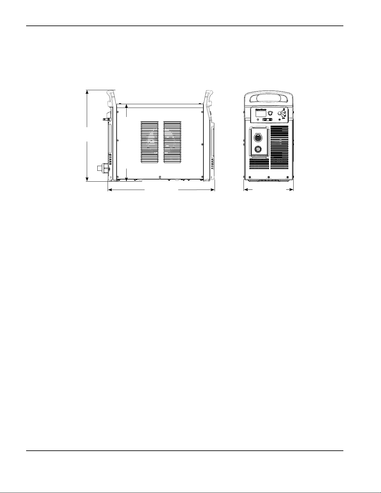
Power supply dimensions
274 mm
(10.8 in.)
592 mm
(23.3 in.)
508 mm
(20.0 in.)
432 mm
(17.0 in.)

SpecificationS
powermax
105
Service Manual 1-5
Component weights (105 A systems)
200–600 V CSA 230–400 V CE 400 V CE 380 V CCC 380 V CCC/
230–400 V CE
Power supply 40 kg (88lbs) 39 kg (87lbs) 35 kg (78lbs) With power cord
35 kg (78 lbs)
No power cord
34 kg (74 lbs)
No power cord
36 kg (79 lbs)
With 7.6 m
(25ft) hand torch
and 7.6 m (25ft)
work lead
45 kg (100lbs) 45 kg (100lbs) 41 kg (91lbs) With power cord
41 kg (91 lbs)
No power cord
39 kg (87 lbs)
No power cord
42 kg (92 lbs)
Hand torch 7.6 m (25 ft) 3.3 kg (7.3 lbs)
Hand torch 15 m (50 ft) 5.9 kg (13.0 lbs)
Hand torch 23 m (75 ft) 8.4 kg (18.5 lbs)
Machine torch 4.6 m (15 ft) 2.4 kg (5.4 lbs)
Machine torch 7.6 m (25 ft) 3.4 kg (7.6 lbs)
Machine torch 11 m (35 ft) 4.5 kg (10.0 lbs)
Machine torch 15 m (50 ft) 6.2 kg (13.7 lbs)
Machine torch 23 m (75 ft) 8.7 kg (19.3 lbs)
Work lead 7.6 m (25 ft) 2.4 kg (5.3 lbs)
Work lead 15 m (50 ft) 4.4 kg (9.6 lbs)
Work lead 23 m (75 ft) 6.1 kg (13.4 lbs)

SpecificationS
1-6 powermax
105
Service Manual
Powermax105 power supply ratings
Rated open-circuit voltage (U
0
)
200–600 V CSA
230–400 V CE
380 V CCC/230–400 V CE
400 V CE
380 V CCC
300 VDC
288 VDC
288 VDC
292 VDC
280 VDC
Output characteristic
1
Drooping
Rated output current (I
2
) 30–105 A
Rated output voltage (U
2
) 160 VDC
Duty cycle at 40° C (104° F) 200–600 V CSA 80% @ 105 A, 480–600 V, 3-PH
70% @ 105 A 240 V, 3-PH
54% @ 105 A 208 V, 3-PH
50% @ 105 A, 200 V, 3-PH
100% @ 94 A, 480–600 V, 3-PH
100% @ 88 A, 240 V, 3-PH
100% @ 77 A, 208 V, 3-PH
100% @ 74 A, 200 V, 3-PH
230–400 V CE
or380VCCC/230–400V CE 80% @ 105 A, 400 V, 3-PH
70% @ 105 A, 230 V, 3-PH
100% @ 94 A, 400 V, 3-PH
100% @ 88 A, 230 V, 3-PH
400 V CE 80% @ 105 A, 400 V, 3-PH
100% @ 94 A, 400 V, 3-PH
380 V CCC 80% @ 105 A, 380 V, 3-PH
100% @ 94 A, 380 V, 3-PH
Operating temperature -10° to 40° C (14° to 104° F)
Storage temperature -25° to 55° C (-13° to 131° F)
Power factor
200–600 V CSA, 3-PH
230–400 V CE, 3-PH
380 V CCC/230–400 V CE, 3-PH
400 V CE, 3-PH
380 V CCC, 3-PH
0.94–0.77
0.94–0.92
0.94–0.92
0.94
0.94
R
sce
– Short Circuit Ratio (CE models only) U
1
– Volts AC rms, 3-PH R
sce
230-400 V CE
400 V CE
275
230

SpecificationS
powermax
105
Service Manual 1-7
EMC classification CISPR 11 (CE models only)
4
Class A
Input voltage (U
1
)/ Input current (I
1
) at
rated output (U
2 MAX
, I
2 MAX
) (See the
Power Supply Setup section for more
information.)
200–600 V CSA 200/208/240/480/600 V, 3-PH, 50/60 Hz
58/56/49/25/22 A
380 V CCC/
230–400 V CE
2,3
230-400 V, 3-PH, 50/60 Hz
50/29 A
230–400 V CE
2,3
230-400 V, 3-PH, 50/60 Hz
50/29 A
400 V CE
3,5
400 V, 3-PH, 50/60 Hz
28 A
380 V CCC 380 V, 3-PH, 50/60 Hz
30 A
Gas type Air Nitrogen
Gas quality Clean, dry, oil-free per
ISO 8573-1 Class 1.2.2
99.95% pure
Recommended gas inlet flow rate/
pressure
Cutting: 220 slpm (460 scfh , 7.7 scfm) @ 5.9 bar (85 psi)
Gouging: 230 slpm (480 scfh, 8.0 scfm) @ 4.8 bar (70 psi)
1
Defined as a plot of output voltage versus output current.
2
Equipment complies with IEC 61000-3-12 provided that the short-circuit power S
sc
is greater than or equal to 5528
KVA at the interface point between the user’s supply and the public system. It is the responsibility of the installer or
user of the equipment to ensure, by consultation with the distribution network operator if necessary, that the equipment
is connected only to a supply with a short-circuit power S
sc
greater than or equal to 5528 KVA.
3
This product meets the technical requirements of IEC 61000-3-3 and is not subject to conditional connection.
4
WARNING: This Class A equipment is not intended for use in residential locations where the electrical power is
provided by the public low-voltage supply system. There may be potential difficulties in ensuring electromagnetic
compatibility in those locations, due to conducted as well as radiated disturbances.
5
Equipment complies with IEC 61000-3-12 provided that the short-circuit power S
sc
is greater than or equal to 4462
KVA at the interface point between the user’s supply and the public system. It is the responsibility of the installer or
user of the equipment to ensure, by consultation with the distribution network operator if necessary, that the equipment
is connected only to a supply with a short-circuit power S
sc
greater than or equal to 4462 KVA.
SpecificationS
1-8 powermax
105
Service Manual
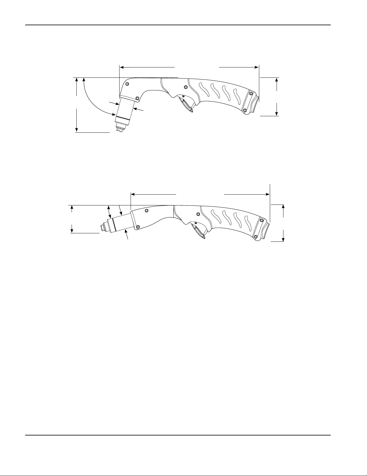
Duramax 75° hand torch dimensions
25.2 cm (9.9 in.)
9.9 cm
(3.9 in.)
75°
angle
25.9 cm (10.2 in.)
5.1 cm
(2.0 in.)
15°
angle
Duramax 15° hand torch dimensions
6.6 cm
(2.6 in.)
6.6 cm
(2.6 in.)
2.5 cm
(1.0 in.)
2.5 cm
(1.0 in.)

SpecificationS
powermax
105
Service Manual 1-9
Duramax 180° full-length machine torch dimensions
39.6 cm
(15.6 in.)
2.5 cm
(1.0 in.)
2.5 cm
(1.0 in.)
3.6 cm (1.4 in.)
outer dimension,
3.3cm (1.3 in.) flat sides
3.6 cm (1.4 in.)
outerdimension,
3.3cm (1.3 in.) flatsides
31.3 cm
(12.3 in.)
20.6 cm
(8.1 in.)
3.5 cm
(1.4 in.)
3.5 cm
(1.4 in.)
Duramax 180° mini machine torch dimensions
16.8 cm
(6.6 in.)
8.4 cm
(3.3 in.)

SpecificationS
1-10 powermax
105
Service Manual
Powermax105 cutting specifications
Handheld cut capacity (material thickness)
Recommended cut capacity at 500 mm/min (20 ipm)* 32 mm (1-1/4 in.)
Recommended cut capacity at 250 mm/min (10 ipm)* 38 mm (1-1/2 in.)
Severance capacity at 125 mm/min (5 ipm)* 50 mm (2 in.)
Pierce capacity (material thickness)
Pierce capacity for handheld cutting, or mechanized
cutting with programmable torch height control
22 mm (7/8 in.)
Pierce capacity for mechanized cutting without
programmable torch height control
20 mm (3/4 in.)
Maximum cut speed** (mild steel)
6 mm (1/4 in.) 5600 mm/min (220 ipm)
12 mm (1/2 in.) 2400 mm/min (95 ipm)
20 mm (3/4 in.) 1300 mm/min (50 ipm)
25 mm (1 in.) 760 mm/min (30 ipm)
32 mm (1-1/4 in.) 510 mm/min (20 ipm)
Gouging capacity
Metal removal rate on mild steel (65 A) 4.8 kg/hr (10.7 lbs/hr)
Metal removal rate on mild steel (85 A) 8.8 kg/hr (19.5 lbs/hr)
Metal removal rate on mild steel (105 A) 9.8 kg/hr (21.7 lbs/hr)
Duramax series torch weights (refer to page 1-5 Component weights (105 A
systems)] )
Duty cycle and voltage information (refer to page 1-6 Powermax105 power
supply ratings)
* Cut capacity speeds are not necessarily maximum speeds. They are the speeds that must be achieved to be rated at
that thickness.
** Maximum cut speeds are the results of Hypertherm’s laboratory testing. Actual cutting speeds may vary based on
different cutting applications.

SpecificationS
powermax
105
Service Manual 1-11
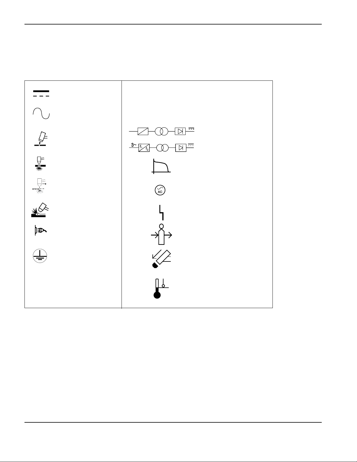
Symbols and markings
Your Hypertherm product may have one or more of the following markings on or near the data plate. Due to differences
and conflicts in national regulations, not all marks are applied to every version of a product.
S mark symbol
The S mark symbol indicates that the power supply and torch are suit able for operations carried out in en vi ron ments with
increased hazard of elec tri cal shock per IEC 60974-1.
CSA mark
Hypertherm products with a CSA mark meet the United States and Canadian regulations for product safety. The products
were evaluated, tested, and certified by CSA-International. Alternatively the product may have amark by one of the other
Nationally Recognized Testing Laboratories (NRTL) accredited in both the United States and Canada, such as Underwriters
Laboratories, Incorporated (UL) or TÜV.
CE marking
The CE marking signifies the manufacturer’s declaration of conformity to applicable European directives andstandards.
Only those versions of Hypertherm products with a CE marking located on or near the dataplate have been tested for
compliance with the European Low Voltage Directive and the European Electromagnetic Compatibility (EMC) Directive.
EMC filters needed to comply with the European EMC Directive are incorporated within versions of the product with a
CEmarking.
GOST-R mark
CE versions of Hypertherm products that include a GOST-R mark of conformity meet the product safety andEMC
requirements for export to the Russian Federation.
c-Tick mark
CE versions of Hypertherm products with a c-Tick mark comply with the EMC regulations required for sale inAustralia and
New Zealand.
s
CCC mark
The China Compulsory Certification (CCC) mark indicates that the product has been tested and found compliant with
product safety regulations required for sale in China.
UkrSEPRO mark
CE versions of Hypertherm products that include a UkrSEPRO mark of conformity meet the product safety and EMC
requirements for export to the Ukraine.
Noise levels
Acceptable noise levels as defined by national and local codes may be exceeded by this plasma system. Always
wear proper ear protection when cutting or gouging. Any noise measurements taken are dependant on the specific
environment in which the system is used. See also Noise can damage hearing in the Safety and Compliance Manual
included with your system. Specific information by product can be found in the Hypertherm downloads library at:
https://www.hypertherm.com/
Click Downloads library, select a product from the Product Type drop-down menu, select “Regulatory” from the
Category drop-down menu, and select “Acoustical Noise Data Sheets” from the Sub Category drop-down menu.
SpecificationS
1-12 powermax
105
Service Manual
O
l
Direct current (DC)
The terminal for the
external protective
(earth) conductor
AC input power
connection
Plasma torch cutting
Alternating current
(AC)
An inverter-based power
source, either 1-phase or
3-phase
Power is OFF
Power is ON
f
1
f
2
1~
Power is ON (LED)
Inlet gas pressure fault
(LCD)
Missing or loose
consumables (LCD)
Power supply is out of
temperature range (LCD)
Volt/amp curve, “drooping”
characteristic
IEC symbols
The following symbols may appear on the power supply data plate, control labels, switches, LEDs, and LCD screen.
System fault (LED)
Plate metal cutting
Expanded metal
cutting
Gouging
AC

powermax
105
Service Manual 2-1
Section 2
POWER SUPPLY SETUP
In this section:
Unpack the Powermax system …………………………………………………………………………………………………………………………………………….2-2
Claims …………………………………………………………………………………………………………………………………………………………………………2-2
Contents ……………………………………………………………………………………………………………………………………………………………………..2-3
Position the power supply……………………………………………………………………………………………………………………………………………………2-4
Prepare the electrical power ……………………………………………………………………………………………………………………………………………….2-4
Install a line-disconnect switch ………………………………………………………………………………………………………………………………….2-5
Requirements for grounding ………………………………………………………………………………………………………………………………………2-5
Power connection for the Powermax105 ……………………………………………………………………………………………………………………………2-6
Three-phase power cord and plug installation ………………………………………………………………………………………………………….2-8
Extension cord recommendations ……………………………………………………………………………………………………………………………………….2-9
Extension cord specifications …………………………………………………………………………………………………………………………………….2-9
Engine-driven generator recommendations …………………………………………………………………………………………………………… 2-10
Prepare the gas supply ……………………………………………………………………………………………………………………………………………………..2-11
Additional gas filtration ……………………………………………………………………………………………………………………………………………. 2-11
Connect the gas supply ………………………………………………………………………………………………………………………………………….. 2-12

Power SuPPly SetuP
2-2 powermax
105
Service Manual
Unpack the Powermax system
1. Verify that all items on your order have been received in good condition. Contact your distributor if any parts are
damaged or missing.
2. Inspect the power supply for damage that may have occurred during shipping. If there is evidence of damage,
refer to Claims below. All communications regarding this equipment must include the model number and the serial
number located on the back of the power supply.
3. Before you set up and operate this Hypertherm system, read the separate Safety and Compliance Manual included
with your system for important safety information.
Claims
Claims for damage during shipment – If your unit was damaged during shipment, youmust file a claim
with the carrier. Hypertherm will furnish you with a copy of the bill oflading upon request. If you need additional
assistance, call the nearest Hypertherm office listed in the front of this manual.
Claims for defective or missing merchandise – If any component is missing or defective, contact your
Hypertherm distributor. If you need additional assistance, call thenearest Hypertherm office listed in the front of
this manual.

Power SuPPly SetuP
powermax
105
Service Manual 2-3
Operator Manual
Safety Manual
Quick Setup Card
Registration Card
Contents
The following illustration shows typical system components. A vinyl cap is installed on torches that ship with new
systems. Consumables are included in the consumables box.
Box with extra consumables
(located next to air filter)
Setup DVD
Or
Or
Remote-start pendant (optional)

Power SuPPly SetuP
2-4 powermax
105
Service Manual
Position the power supply
Locate the power supply near an appropriate power receptacle for your installation:
• 200–600 volts (3-phase, CSA certified)
• 230–400 volts (3-phase, CE certified)
• 380/230–400 volts (3-phase, CCC/CE certified) without power cord
Note: To maintain CE certification, install power cord kit 228886.
• 400 volts (3-phase, CE certified)
• 380 volts (3-phase, CCC certified).
The power supply has a 3 m (10 ft) power cord (depending upon the model). Allow at least 0.25 m (10 inches) of space
around the power supply for proper ventilation.
The power supply is not suitable for use in rain or snow.
To avoid toppling, do not set the power supply on an incline greater than 10 degrees.
Prepare the electrical power
Hypertherm (designated HYP on the data plate) input current ratings are used to determine conductor sizes for power
connection and installation instructions. The HYP rating is determined under maximum normal operating conditions and
the higher HYP input current value should be used for installation purposes.
The maximum output voltage will vary based on your input voltage and the circuit’s amperage. Because the current draw
varies during startup, slow-blow fuses are recommended as shown in the charts on page 2-6. Slow-blow fuses can
withstand currents up to 10 times the rated value for short periods of time.
Caution: Protect the circuit with appropriately sized time-delay (slow-blow) fuses and a
line-disconnect switch.

Power SuPPly SetuP
powermax
105
Service Manual 2-5
Install a line-disconnect switch
Use a line-disconnect switch for each power supply so that the operator can turn off the incoming power quickly in an
emergency. Locate the switch so that it is easily accessible to the operator. Installation must be performed by a licensed
electrician according to national and local codes. The interrupt level of the switch must equal or exceed the continuous
rating of the fuses. In addition, the switch should:
• Isolate the electrical equipment and disconnect all live conductors from the incoming supply voltage when in the
OFF position.
• Have one OFF and one ON position that are clearly marked with O (OFF) and I (ON).
• Have an external operating handle that can be locked in the OFF position.
• Contain a power-operated mechanism that serves as an emergency stop.
• Have appropriate slow-blow fuses installed. See page 2-6 Power connection for the Powermax105 for
recommended fuse sizes.
Requirements for grounding
To ensure personal safety, proper operation, and to reduce electromagnetic interference (EMI), the power supply must
be properly grounded.
• The power supply must be grounded through the power cord according to national and local electrical codes.
• Three-phase service must be of the 4-wire type with a green or green/yellow wire for protective earth ground
and must comply with national and local requirements.
• Refer to the separate Safety and Compliance Manual included with your system for more information on
grounding.

Power SuPPly SetuP
2-6 powermax
105
Service Manual
Power connection for the Powermax105
Powermax105 3-phase systems include the following models:
• The 200–600 V CSA model is a universal power supply that can automatically adjust to operate with
ACvoltages from 200 to 600 V.
• The 230–400 V CE model can automatically adjust from 230 to 400 V.
• The 380 V CCC/230–400 V CE model can automatically adjust from 230 to 400 V.
Note: To maintain CE certification, install power cord kit 228886.
• The 400 V CE model is 400 V only.
• The 380 V CCC model is 380 V only.
The rated output is 30–105 A, 160 VDC.
200–600 V CSA,
Input voltage (V) 200 208 240 480 600
Input current (A) at rated output (16.8 kw) 58 56 49 25 22
Input current (A) at arc stretch 82 82 78 40 35
Fuse, slow-blow (A) 80 80 80 40 40
230–400 V CE
Input voltage (V) 230 400
Input current (A) at rated output (16.8 kw) 50 29
Input current (A) at arc stretch 80 46
Fuse, slow-blow (A) 80 50

Power SuPPly SetuP
powermax
105
Service Manual 2-7
380 V CCC/230–400 V CE
Input voltage (V) 230 400 380
Input current (A) at rated output (16.8 kw) 50 29 30
Input current (A) at arc stretch 80 46 42
Fuse, slow-blow (A) 80 50 50
400 V CE
Input voltage (V) 400
Input current (A) at rated output (16.8 kw) 28
Input current (A) at arc stretch 44
Fuse, slow-blow (A) 50
380 V CCC
Input voltage (V) 380
Input current (A) at rated output (16.8 kw) 30
Input current (A) at arc stretch 42
Fuse, slow-blow (A) 50

Power SuPPly SetuP
2-8 powermax
105
Service Manual
Three-phase power cord and plug installation
Powermax105 power supplies are shipped with the following power cords:
• CSA models: 6 AWG 4-wire power cord
• 230–400 V CE: 10 mm
2
, 4-wire HAR power cord
• 380 V CCC/230–400 V CE ships without a power cord
Note: To maintain CE certification, install power cord kit 228886.
• 400 V CE: 6 mm
2
, 4-wire HAR power cord
• 380 V CCC: 6 mm
2
, 4-wire CCC power cord (some models ship without a power cord)
To operate the Powermax105, use a plug that meets national and local electrical codes. The plug must be connected to
the power cord by a licensed electrician.
Strip and prepare the power cord wires as shown below.
L1
L3
L2
L2
L1
L3
Ground
6 mm (.25 in.)
419 mm
(16.5 in.)
203 mm
(8 in.)
CSA
Route lead through strain
relief and tighten

Power SuPPly SetuP
powermax
105
Service Manual 2-9
Extension cord recommendations
Any extension cord must have an appropriate wire size for the cord length and system voltage. Usea cord that meets
national and local codes.
The table on the next page provides the recommended gauge sizes for various lengths and input voltages. The lengths
in the tables are the length of the extension cord only; they do not include the power supply’s power cord.
Extension cord specifications
Extension cord length
< 3 m
(<10ft)
3–7.5 m
(10–25ft)
7.5–15 m
(25–50ft)
15–30 m
(50–100ft)
30–45 m
(100–150ft)
200–600 V CSA
Input voltage (VAC) Phase mm
2
(AWG) mm
2
(AWG) mm
2
(AWG) mm
2
(AWG) mm
2
(AWG)
200–240 3 16 (6) 16 (6) 16 (6) 25 (4) 35 (2)
480–600 3 6 (10) 6 (10) 6 (10) 6 (10) 6 (10)
230–400 V CE
Input voltage (VAC) Phase mm
2
mm
2
mm
2
mm
2
mm
2
230 3 16 16 16 25 25
400 3 10 10 10 10 10
380 V CCC/230–400 V CE
Input voltage (VAC) Phase mm
2
mm
2
mm
2
mm
2
mm
2
230 3 16 16 16 25 25
400 3 10 10 10 10 10
380 3 10 10 10 10 10
400 V CE
Input voltage (VAC) Phase mm
2
mm
2
mm
2
mm
2
mm
2
400 3 10 10 10 10 10
380 V CCC
Input voltage (VAC) Phase mm
2
mm
2
mm
2
mm
2
mm
2
380 3 10 10 10 10 10

Power SuPPly SetuP
2-10 powermax
105
Service Manual
Engine-driven generator recommendations
Generators used with the Powermax105 should satisfy the following requirements:
200–600 V CSA
3-phase, 50/60 Hz, 200–600 VAC (480 VAC recommended for best performance)
230–400 V CE
3-phase, 50/60 Hz, 230–400 VAC (400 VAC recommended for best performance)
380 V CCC/230–400 V CE
3-phase, 50/60 Hz, 230–400 VAC (400 VAC recommended for best performance)
400 V CE
3-phase, 50/60 Hz, 400 VAC (400 VAC recommended for best performance)
380 V CCC
3-phase, 50/60 Hz, 380 VAC (380 VAC recommended for best performance)
Engine drive
rating
System output
current
Performance
(arcstretch)
30 kw 105 A Full
22.5–25 105 A Limited
20 kw 85 A Full
15 kw 70 A Limited
15 kw 65 A Full
12 kw 65 A Limited
12 kw 40 A Full
8 kw 40 A Limited
8 kw 30 A Full
Note: Based on the generator rating, age, and condition, adjust the cutting current as needed.
If a fault occurs while using a generator, turning the power switch quickly to OFF and then to ON again
(sometimes called a “quick reset”) may not clear the fault. Instead, turn OFF the power supply and wait 60 to
70 seconds before turning ON again.

Power SuPPly SetuP
powermax
105
Service Manual 2-11
Prepare the gas supply
The air can be supplied by a compressor or from high-pressure cylinders. A high-pressure regulator must be used on
either type of supply and must be capable of delivering gas to the air inlet on the power supply.
If the supply quality is poor, cut speeds decrease, cut quality deteriorates, cutting thickness capability decreases, and
the life of the consumables shortens. For optimal performance, the gas should be compliant with ISO8573-1:2010,
Class 1.2.2 (that is, it should have a maximum number of solid particulate per m
3
of <20,000 for particle sizes in the
range of 0.1-0.5 microns, <400 for particle sizes in the range of 0.5-1 microns, and <10 for particle sizes in the range
of 1-5 microns). The maximum water vapor dew point should be <-40° C (-40° F). The maximum oil (aerosol, liquid, and
vapor) content should be less than 0.1 mg/m
3
.
Additional gas filtration
When site conditions introduce moisture, oil, or other contaminants into the gas line, use a 3-stage coalescing filtration
system, such as the Eliminizer filter kit (part number 228890) available from Hypertherm distributors. A 3-stage filtering
system works as shown below toclean contaminants from the gas supply.
The filtering system should be installed between the gas supply and the power supply. Additional gas filtration may
increase the required minimum inlet pressure.
Gas supply
Powermax105
Water and particle filter Oil filter Oil vapor filter

Power SuPPly SetuP
2-12 powermax
105
Service Manual
Connect the gas supply
Connect the gas supply to the power supply using an inert-gas hose with a 9.5mm (3/8 inch) internal diameter and a
1/4NPT quick-disconnect coupler, or a 1/4 NPT x G-1/4 BSPP (CE units) quick-disconnect coupler.
The recommended inlet pressure while gas
is flowing is 5.9 – 9.3 bar (85 – 135 psi).
WARNING
Do not allow the gas supply pressure to exceed 9.3 bar (135 psi). The filter bowl may explode if this
pressure is exceeded.

Power SuPPly SetuP
powermax
105
Service Manual 2-13
Minimum inlet pressure (while gas is flowing)
This table shows the minimum required inlet pressure when the recommended inlet pressure is not available.
Torch lead length
7.6 m (25 ft) 15.2 m (50 ft) 22.9 m (75 ft)
Cutting 5.2 bar (75 psi) 5.5 bar (80 psi) 5.9 bar (85 psi)
Gouging 4.1 bar (60 psi) 4.5 bar (65 psi) 4.8 bar (70 psi)
Gas flow rates
Cutting 220 slpm (460 scfh, 7.7 scfm) at a minimum 5.9 bar (85 psi)
Gouging 230 slpm (480 scfh, 8.0 scfm) at a minimum 4.8 bar (70 psi)

Power SuPPly SetuP
2-14 powermax
105
Service Manual

powermax
105
Service Manual 3-1
Section 3
BASIC SYSTEM OPERATIONS
In this section:
Controls and indicators ……………………………………………………………………………………………………………………………………………………….3-2
Rear controls ………………………………………………………………………………………………………………………………………………………………3-2
Front controls and LEDs …………………………………………………………………………………………………………………………………………….3-2
Status screen ……………………………………………………………………………………………………………………………………………………………..3-4
Operating the Powermax105 ………………………………………………………………………………………………………………………………………………3-6
Connect the electrical power, gas supply, and torch lead ……………………………………………………………………………………….3-6
Attach the work lead to the power supply …………………………………………………………………………………………………………………3-7
Attach the work clamp to the workpiece …………………………………………………………………………………………………………………..3-8
Turn ON the system ……………………………………………………………………………………………………………………………………………………3-9
Set the operating mode switch ………………………………………………………………………………………………………………………………….3-9
Check the indicators ………………………………………………………………………………………………………………………………………………..3-10
Manually adjusting the gas pressure ……………………………………………………………………………………………………………………….3-10
Adjusting the current (amperage) …………………………………………………………………………………………………………………………… 3-11
Electrode end-of-life detection feature ……………………………………………………………………………………………………………………………. 3-11
Understanding duty-cycle limitations ………………………………………………………………………………………………………………………………. 3-12

Basic system OperatiOns
3-2 powermax
105
Service Manual
Controls and indicators
Powermax105 power supplies have the following: ON/OFF switch, adjustment knob, automatic/manual pressure setting
mode selector, current/gas selector, operating mode switch, indicator LEDs, and a status screen. These controls and
indicators are described on the following pages.
Rear controls
ON (I)/OFF (O) power switch
Activates the power supply and its control circuits.
Front controls and LEDs
Fault LED (yellow)
Power ON LED
(green)
Status screen
Automatic/manual pressure
setting mode selector
Current/gas
selector
Operating
modeswitch
Modes described
onnext page
Adjustment knob
Fault LED (yellow)
When illuminated, this LED indicates that there is a fault with the power supply.
AC
Power ON LED (green)
When illuminated, this LED indicates that the power switch has been set to I (ON) and that the safety
interlocks are satisfied. When blinking, the power supply has a fault.

Basic system OperatiOns
powermax
105
Service Manual 3-3
Operating mode switch
The operating mode switch can be set in one of four positions:
• Continuous pilot arc. Cuts expanded metal or grate.
• Non-continuous pilot arc. Cuts or pierces metal plate. This is the standard
setting for normal drag-cutting.
• Gouge. Gouges metal plate.
• Torch lock. Same as the non-continuous pilot arc mode except the torch is
locked in the ON position when you release the trigger during a cut. The torch
goes out when the transfer is lost or the torch is retriggered.
Automatic/manual pressure setting mode selector
The selector switches between automatic and manual mode. In automatic mode, the power supply
automatically sets the gas pressure based upon the torch type and lead length and the adjustment
knob sets only the amperage. In manual mode, the adjustment knob sets either the gas pressure or the
amperage. This LED is illuminated in manual mode.
Note: Manual mode should be used by experienced users who need to optimize the gas setting
(override the automatic gas setting) for a specific cutting application.
When you switch from manual mode to automatic mode, the power supply automatically sets the gas
pressure and the amperage setting is unchanged. When you switch from automatic mode to manual
mode, the power supply remembers the previous manual gas pressure setting and the amperage
setting is unchanged.
When you reset the power, the power supply remembers the previous mode, gas pressure, and
amperage settings.
Current/gas selector
When in manual mode, this selector toggles between amperage and gas pressure for manual
adjustments using the adjustment knob.
Adjustment knob
This knob adjusts the amperage. When operating in manual mode, this knob can also adjust the
gas pressure, overriding the automatic setting for optimized applications.

Basic system OperatiOns
3-4 powermax
105
Service Manual
Status screen
The status screen shows system status and fault information.
Torch started
Fault icon
Fault code
Torch is cutting
Remote
connected
Electrode end of life
detection manually disabled
Current setting (amps)
Current selection cursor
Pressure selection cursor
Pressure
setting
Visual pressure
setting
Gas pressure indicators
In manual mode, the gas pressure is displayed in bar and psi. The gas pressure bar is also a visual indicator of the gas
pressure.
Gas pressure bar
When the arrow is centered in the vertical bar (the reference pressure of the automatic pressure setting), the
gas pressure is set to the preset (factory-defined) value. If the pressure is higher than the preset value, the
arrow appears above the mid-point of the bar. If the pressure is lower than the preset value, the arrow appears
below the mid-point of the bar.
Note: In automatic mode, the power supply adjusts the pressure to the preset value. You can use manual
mode to adjust the pressure to satisfy the needs of a particular cutting job. Refer to page 3-10
Manually adjusting the gas pressure.
System status icons
The screen displays icons to indicate the system’s status.
Torch started
Indicates that the torch has received a start signal.
Torch is cutting
Indicates that the cutting arc has transferred to the metal and the torch is cutting.
Remote control
Indicates that a remote control or CNC is controlling the power supply using serial communications. All local
controls are disabled.
Electrode end-of-life detection manually disabled
Indicates that the electrode end-of-life detection feature is manually disabled.

Basic system OperatiOns
powermax
105
Service Manual 3-5
Fault codes
When a power supply or torch fault occurs, the system displays a fault code in the lower-left corner of the status screen
and displays a corresponding fault icon above the code. The first digit is always zero. The other two digits identify the
problem. Fault code information is included later in this manual.
Note: Only one fault code is displayed. If more than one fault occurs at the same time, only the fault code with the
highest priority is displayed.
Fault icons
The fault icons that appear on the left side of the status screen are described below. A fault code also appears to
identify the fault. Refer to the troubleshooting information later in this manual.
Warning
The system continues to run.
Fault
The system stops cutting. If you can not correct the problem and restart the system, contact your distributor
or Hypertherm Technical Service.
Error
The system requires service. Contact your distributor or Hypertherm Technical Service.
Torch cap sensor
Indicates that the consumables are loose, improperly installed, or missing. Turn OFF the power, properly
install the consumables, and turn ON the system again to reset the power supply.
Temperature
Indicates that the temperature of the power supply power module is outside the acceptable operating range.
Gas
Indicates that the gas is disconnected from the rear of the power supply or there is a problem with the gas
supply.
Internal Serial Communications Interface
Indicates a problem with the SCI communications between the control board and the DSP board.

Basic system OperatiOns
3-6 powermax
105
Service Manual
Operating the Powermax105
Follow the steps below to begin cutting or gouging with the Powermax system.
Note: This section provides basic operating instructions. Before operating your Powermax in a production
environment, refer to the Hand Torch Setup section or the Machine Torch Setup section.
Connect the electrical power, gas supply, and torch lead
For information on connecting the proper plug to the power cord, refer to the Power Supply Setup section.
Plug in the power cord and connect the gas supply line. For more information about the electrical requirements and
the gas supply requirements of the Powermax, see the Power Supply Setup section. To connect the torch, push the
FastConnect
TM
connector into the receptacle on the front of the power supply You will attach the work lead in the next
section.
Power cord (does not
ship with plug)
Work lead
Torch lead
Gas supply
line
 Loading…
More products and manuals for Equipment Hypertherm
| Models | Document Type |
|---|---|
|
HD1070 Product Configuration |
User Manual
28 pages |
|
PAC500 Product Configuration |
User Manual
58 pages |
|
Powermax30 Service Manual power board replacement |
User Manual
4 pages |
|
Powermax30 AIR Service Manual |
User Manual
223 pages |
|
Powermax30 XP Service Manual |
User Manual
201 pages |
|
RT60 Retrofit Torch |
User Manual
51 pages |
|
SensorOHC |
User Manual
26 pages |
|
Powermax45 Service Manual |
User Manual
149 pages |
|
Powermax125 Service Manua |
User Manual
317 pages |
|
HSD130 Remote High Frequency Console |
User Manual
195 pages |
|
HSD130 Remote High Frequency Console |
User Manual
195 pages |
|
HSD130 Local High Frequency |
User Manual
187 pages |
|
HSD130 Local High Frequency |
User Manual
187 pages |
|
HSD130 Remote High Frequency Console |
User Manual
195 pages |
|
HSD130 Remote High Frequency Console |
User Manual
195 pages |
|
HSD130 Remote High Frequency Console |
User Manual
195 pages |
|
HT4400 |
User Manual
76 pages |
|
HT4400 |
User Manual
76 pages |
|
HT4400 |
User Manual
184 pages |
|
MAX200 Hand Torch Plasma Arc Cutting System |
User Manual
71 pages |


Партек — официальный дилер и системный интегратор HYPERTHERM в России

Оборудование и расходные детали для плазменной резки
☰ Меню сайта
|
|
| Инструкция пользователя на источник плазменной резки Powermax 105 для ручной и механизированной резки.
По вопросам зап.частей или покупки оборудования звоните +7-812-602-03-02 или отправьте запрос на почту info@partech.ru |