
Download or browse on-line these Manual for Honeywell XLS80e Control Systems.
Summary of Contents:
 |
[Page 1] Honeywell XLS80e XLS80e Panel Configuration Manual March 2007, Issue 9 |
 |
[Page 2] Honeywell XLS80e i XLS80e Fire Alarm Control Panels Honeywell, Issue 9 March 2007 Quick Contents Reference by Section XLS80e 0 1 2 3 4 5 6 7 8 9 User Menu: 3:Log/display/print menu 4:Set Clock 5:View Alarm Count 6: Service Mon 01-May-2000 11:20:07 Configuratio… |
 |
[Page 3] Honeywell XLS80e ii XLS80e Fire Alarm Control Panels Honeywell, Issue 9 March 2007 Contents 1 Introduction 1 1.1 Associated Documents 1 1.2 System Design and Planning 1 1.3 Glossary of Icons 2 1.4 Software Version Number 4 1.5 EN54 Functions 4 1.6 Ancillary Functions… |
 |
[Page 4] Honeywell XLS80e iii XLS80e Fire Alarm Control Panels Honeywell, Issue 9 March 2007 4.4 Menu Displays 25 4.4.1 To Display the User Menu 25 4.4.2 To Navigate Through the Menus 26 4.4.3 Menu Structure 27 5 Loop Device Configuration 29 5.1 Configure Individual Device 29… |
 |
[Page 5] Honeywell XLS80e iv XLS80e Fire Alarm Control Panels Honeywell, Issue 9 March 2007 7.8 Extinguishing System Function 77 7.8.1 Types of Control Matrix Entry 77 7.8.2 Minimum Configuration 77 7.8.3 Device Selection 78 7.8.4 HOLD Options 78 7.9 Logic Operation with Tran… |
 |
[Page 6] Honeywell XLS80e v XLS80e Fire Alarm Control Panels Honeywell, Issue 9 March 2007 11.19 Day/Night Modes Configuration 104 11.20 Extinguishing System 105 11.21 Alarm Coincidence 106 11.22 Network Settings 107 11.23 Thermal Alarm Verification Time 107 12 User Menu at L… |
 |
[Page 7] Honeywell XLS80e vi XLS80e Fire Alarm Control Panels Honeywell, Issue 9 March 2007 Appendix 1 Upgrading the Panel Software A1-1 Appendix 2 Available Loop Device Types A2-1 Appendix 3 XLSNET Network Configuration A3-1 |
 |
[Page 8] Honeywell XLS80e 1 Honeywell, Issue 9 March 2007 XLS80e Fire Alarm Control Panels 1 Introduction This manual provides recommended procedures for the successful configuration of a complete Honeywell XLS80e Series integrated Fire Control System (including repeater pane… |
 |
[Page 9] Honeywell XLS80e 2Honeywell, Issue 9 March 2007 XLS80e Fire Alarm Control Panels 1.3 Glossary of Icons Throughout this manual, and the other related XLS80e Series manuals, a number of icons are used in the illustrations to help clarify, or simplify, particular config… |
 |
[Page 10] Honeywell XLS80e 3 Honeywell, Issue 9 March 2007 XLS80e Fire Alarm Control Panels m. Mains power connected and switched ON. n. Panel batteries power connected/ disconnected. o. Manual Call Point (MCP)/Sensor. p. Access 3A passcode entry requested to continue with sel… |
 |
[Page 11] Honeywell XLS80e 4Honeywell, Issue 9 March 2007 XLS80e Fire Alarm Control Panels 1.4 Software Version Number The XLS80e Series control panel software version can be viewed by performing a lamp test function. Software version numbers are displayed for the following: a… |
 |
[Page 12] Honeywell XLS80e 5 Honeywell, Issue 9 March 2007 XLS80e Fire Alarm Control Panels The following features are provided by the Power Supply Unit (PSU) of the XLS80e Series Fire Control Panel Range to comply with EN 54-4: Feature of the XLS80e PSU EN 54-4 Clause Derive … |
 |
[Page 13] Honeywell XLS80e 6Honeywell, Issue 9 March 2007 XLS80e Fire Alarm Control Panels Ancillary Function Manual Section Refs. Loop start-up boost 11.8 Calendar-based automatic test selection 11.6 Automatic cancellation of disablements 11.7 Mains Fail Fault additional dela… |
 |
[Page 14] Honeywell XLS80e 7 XLS80e Fire Alarm Control Panels Honeywell, Issue 9 March 2007 2 Power On/Start Up To power up the system from a completely powered-down condition: 1 Connect the two leads (A) from within the panel to the two 12 V sealed lead-acid batteries and the… |
 |
[Page 15] Honeywell XLS80e 8 XLS80e Fire Alarm Control Panels Honeywell, Issue 9 March 2007 b. If the panel has not been configured with any sensor or module data, i.e. the normal system status at initial power up, the panel displays ‘*UNCONFIGURED*’ unless it is part of … |
 |
[Page 16] Honeywell XLS80e 9 XLS80e Fire Alarm Control Panels Honeywell, Issue 9 March 2007 3 Panel Configuration Overview This section gives a brief guide to the methods for configuring the XLS80e Series panels. 3.1 Where to Access the Configuration Actions The panel can be c… |
 |
[Page 17] Honeywell XLS80e 10 XLS80e Fire Alarm Control Panels Honeywell, Issue 9 March 2007 3.2 Configuration Actions The following configuration actions can be performed: a. An unconfigured panel can scan the loops and learn what devices are installed, either automatically o… |
 |
[Page 18] Honeywell XLS80e 11 XLS80e Fire Alarm Control Panels Honeywell, Issue 9 March 2007 3.3 Using the Panel Controls and Indicators All of the configuration operations described in this manual can be done using the panel pushbuttons and Liquid Crystal Display (LCD), with … |
 |
[Page 19] Honeywell XLS80e 12 XLS80e Fire Alarm Control Panels Honeywell, Issue 9 March 2007 3.3.2 Liquid Crystal Display The 6-line x 40 character display (using 240 x 64 pixels) provides a menu structure for the operation and configuration of the panel. Most of the operation… |
 |
[Page 20] Honeywell XLS80e 13 XLS80e Fire Alarm Control Panels Honeywell, Issue 9 March 2007 3.4 Using the Off-line Support Tool This is a means of preparing the configuration data, using an optionally-supplied software tool which you can use without any connection to the pane… |
 |
[Page 21] Honeywell XLS80e 14 XLS80e Fire Alarm Control Panels Honeywell, Issue 9 March 2007 3.6 Learn Devices on Loops The panel scans the loops and detects what devices are fitted. This can be done on an unconfigured panel. Section 5.3 describes how to start, run and end a c… |
 |
[Page 22] Honeywell XLS80e 15 XLS80e Fire Alarm Control Panels Honeywell, Issue 9 March 2007 Limitations of the Auto-learn Method If the auto-learn method is used on an incomplete system it will give the false impression that the system is fully operational. In such cases,… |
 |
[Page 23] Honeywell XLS80e 16 XLS80e Fire Alarm Control Panels Honeywell, Issue 9 March 2007 3.9 Text Editing There are three types of text that can be entered and edited: a. The panel or site name. b. The zone description. c. The device location text, which is shown on the di… |
 |
[Page 24] Honeywell XLS80e 17 XLS80e Fire Alarm Control Panels Honeywell, Issue 9 March 2007 3.11 Time-of-Day This facility allows panel functions to be modified depending upon the time of day. There are three major applications: a. Altering the sensitivity of sensors at certa… |
 |
[Page 25] Honeywell XLS80e 18 XLS80e Fire Alarm Control Panels Honeywell, Issue 9 March 2007 3.14 System Networking The XLS80e Fire Control system is designed so that control panels can work either as stand- alone units or networked with other panels. When networked, each pane… |
 |
[Page 26] Honeywell XLS80e 19 XLS80e Fire Alarm Control Panels Honeywell, Issue 9 March 2007 3.15 Delays Either the sounders or the fire alarm routing equipment (remote fire outputs) which is used to summon the fire brigade can be delayed: a. To activate sounders immediately b… |
 |
[Page 27] Honeywell XLS80e 20Honeywell, Issue 9 March 2007 XLS80e Fire Alarm Control Panels 4 The Display — Tabs, Events and Menus 4.1 Introduction 4.1.1 Status: NORMAL The Status: NORMAL display appears when: a. No alarm or test conditions exist, and b. No menus are being acc… |
 |
[Page 28] Honeywell XLS80e 21 Honeywell, Issue 9 March 2007 XLS80e Fire Alarm Control Panels 4.2 Tabs When tabs are displayed, use the CHANGE TABS key to scroll through the tabs and thus display the corresponding data. The tabs are (in descending order of priority): EXTINGUISH… |
 |
[Page 29] Honeywell XLS80e 22Honeywell, Issue 9 March 2007 XLS80e Fire Alarm Control Panels 4.3 Event Displays When a fire alarm, pre-alarm, fault, disablement, walk test, evacuation, or auxiliary input activation (if logging is configured) occurs, an event display replaces th… |
 |
[Page 30] Honeywell XLS80e 23 Honeywell, Issue 9 March 2007 XLS80e Fire Alarm Control Panels Tech.Alarm: ZONES: 1; Events: 2 Panel 13:Security Office L4 S05 Corridor 13 Ceiling Sensor GAS Tech.Alarm User 27-Jul-2004 11:20:07 P13 ZONE 31 (x2) … |
 |
[Page 31] Honeywell XLS80e 24Honeywell, Issue 9 March 2007 XLS80e Fire Alarm Control Panels Maint Tab This displays the maintenance status of any MCS and Acclimate sensors installed on the loops. If the panel is connected to an XLSnet network and more than one panel contains s… |
 |
[Page 32] Honeywell XLS80e 25 Honeywell, Issue 9 March 2007 XLS80e Fire Alarm Control Panels 4.4 Menu Displays 4.4.1 To Display the User Menu To display the User Menu when the system status is Normal, enter the passcode. To use the Configuration menu and to use some options on… |
 |
[Page 33] Honeywell XLS80e 26Honeywell, Issue 9 March 2007 XLS80e Fire Alarm Control Panels 6 4.4.2 To Navigate Through the Menus In this example it is desired to display the Configuration Menu, which is option 6 on the User Menu. With the User Menu displayed, press 6 to go … |
 |
[Page 34] Honeywell XLS80e 27 Honeywell, Issue 9 March 2007 XLS80e Fire Alarm Control Panels 4.4.3 Menu Structure Note: ** Requires access 3 passcode. The menu primarily used in this manual is the Configuration Menu, therefore its sub-menus are shown in greater detail than is … |
 |
[Page 35] Honeywell XLS80e 28Honeywell, Issue 9 March 2007 XLS80e Fire Alarm Control Panels Note: If access level 2 is entered by use of the keyswitch, no decision has been made by the user to enter a specific access level passcode. In this case the ‘CONFIGURATION’ menu op… |
 |
[Page 36] Honeywell XLS80e 29 XLS80e Fire Alarm Control Panels Honeywell, Issue 9 March 2007 5 Loop Device Configuration You can configure loop devices: a. Individually (Section 5.1). b. As a group (Section 5.2). c. As a system (Section 5.3), learning the loops either automati… |
 |
[Page 37] Honeywell XLS80e 30 XLS80e Fire Alarm Control Panels Honeywell, Issue 9 March 2007 4 In this example SENSOR was chosen. The procedure for choosing a MODULE is the same. Enter the device number. Leading zeros are optional. In this example the device is an optical sens… |
 |
[Page 38] Honeywell XLS80e 31 XLS80e Fire Alarm Control Panels Honeywell, Issue 9 March 2007 5.1.2 Change Device Configuration — Sensors The following can be altered for sensors: a. The device type. b. The zone or cell in which the device is placed. c. The device location text… |
 |
[Page 39] Honeywell XLS80e 32 XLS80e Fire Alarm Control Panels Honeywell, Issue 9 March 2007 5.1.2.2 Edit Device Zone or Cell Zone Number Enter the zone number within the displayed range. RANGE! is displayed if the entered number is out of range. For details of zone ranges, re… |
 |
[Page 40] Honeywell XLS80e 33 XLS80e Fire Alarm Control Panels Honeywell, Issue 9 March 2007 5.1.2.3 Edit Device Location Text Edit the text description which is used for the various tab displays (e.g. fire, fault) and for printing at the printer. Section 6 describes how to us… |
 |
[Page 41] Honeywell XLS80e 34 XLS80e Fire Alarm Control Panels Honeywell, Issue 9 March 2007 Pre-alarm Again the default setting is 5 for all types of sensor except Photo/Thermal (MULT) and MCS. The alarm and pre-alarm ranges do not overlap, except for MULT and MCS for which t… |
 |
[Page 42] Honeywell XLS80e 35 XLS80e Fire Alarm Control Panels Honeywell, Issue 9 March 2007 5.1.2.5 Edit Verification Delay Set the verification delay within the displayed range. RANGE! is displayed if the entered number is out of range. Refer to Section 13 for recommended ve… |
 |
[Page 43] Honeywell XLS80e 36 XLS80e Fire Alarm Control Panels Honeywell, Issue 9 March 2007 5.1.2.8 LED Blink Options Select whether the device’s LEDs follow the panel setting (Section 11.2) or are set to blink or not (non-blink). 5.1.2.9 LED Also Controls Select the requir… |
 |
[Page 44] Honeywell XLS80e 37 XLS80e Fire Alarm Control Panels Honeywell, Issue 9 March 2007 5.1.3 MULTI, MCS & GAS Sensor Interface Sensitivities 5.1.3.1 Photo/Thermal (MULT) Sensors Device type MULT applies to the TC840ME. ACCLIMATE, has a Thermal-Only mode, i.e. a mode… |
 |
[Page 45] Honeywell XLS80e 38 XLS80e Fire Alarm Control Panels Honeywell, Issue 9 March 2007 5.1.3.2 MCS Sensors The system supports Multi-criteria (MCS) sensors. The MCS4 sensor has the capability for carbon monoxide, photoelectronic (optical), infra-red and thermal detection… |
 |
[Page 46] Honeywell XLS80e 39 XLS80e Fire Alarm Control Panels Honeywell, Issue 9 March 2007 5.1.4 Change Device Configuration — Modules The following can be altered for modules: a. The device type. b. The zone or cell in which the device is placed. c. The device location text… |
 |
[Page 47] Honeywell XLS80e 40 XLS80e Fire Alarm Control Panels Honeywell, Issue 9 March 2007 Auxiliary Modules Any Input (MMX) module can be defined as logical type AUXILIARY. To make use of several special Control Matrix facilities, certain input modules must be defined as lo… |
 |
[Page 48] Honeywell XLS80e 41 XLS80e Fire Alarm Control Panels Honeywell, Issue 9 March 2007 Alarm Supervision Set the alarm supervision ON or OFF. Note: It is not possible to set Manual Call Points (device type MCP) ALARM threshold to OFF. Short- and Open-Circuit Supervision … |
 |
[Page 49] Honeywell XLS80e 42 XLS80e Fire Alarm Control Panels Honeywell, Issue 9 March 2007 5.1.4.8 Bell and CTRL Module Options Additional options (SILENCEABLE and NORMAL PULSE) are displayed for CMX modules of types BELL and CTRL. Module SILENCE Options This option determin… |
 |
[Page 50] Honeywell XLS80e 43 XLS80e Fire Alarm Control Panels Honeywell, Issue 9 March 2007 5.2 Configure Group of Devices This option allows a group of devices to be deleted or all set to the same type. The devices must be at consecutive addresses on the same loop and in the… |
 |
[Page 51] Honeywell XLS80e 44 XLS80e Fire Alarm Control Panels Honeywell, Issue 9 March 2007 5 Select either DELETE or select the device type to which the group of devices is to be set. Sensor types are defined in Section 5.1.2.1 and module types are defined in Section 5.1.4.1… |
 |
[Page 52] Honeywell XLS80e 45 XLS80e Fire Alarm Control Panels Honeywell, Issue 9 March 2007 5.3 Learn Devices on Loops This option allows the panel to detect and automatically configure devices that it finds already connected to the loops. If the panel has already been config… |
 |
[Page 53] Honeywell XLS80e 46 XLS80e Fire Alarm Control Panels Honeywell, Issue 9 March 2007 5 Select the loop at which the learn process is to end (‘n’ represents the highest loop on the system). 6 If you want to learn all the devices on the loop selected in step 5, selec… |
 |
[Page 54] Honeywell XLS80e 47 XLS80e Fire Alarm Control Panels Honeywell, Issue 9 March 2007 5.3.2 Run in Auto-Learn Mode If you select this option, then: Note: Steps 1 to 3 are omitted if only sensors were selected in the procedure of Section 5.3.1. The choices made in these … |
 |
[Page 55] Honeywell XLS80e 48 XLS80e Fire Alarm Control Panels Honeywell, Issue 9 March 2007 5 Set the zone into which new sensors or modules will be placed. If you select the ‘0’ option: a. If a newly-learnt device replaces an existing device of the wrong type, it is plac… |
 |
[Page 56] Honeywell XLS80e 49 XLS80e Fire Alarm Control Panels Honeywell, Issue 9 March 2007 5.3.3 Run in Manual Learn Mode If you select this option, then: 1 Press to begin the manual learn process. 2 As the learn process progresses, the status is displayed. 3 If a differen… |
 |
[Page 57] Honeywell XLS80e 50 XLS80e Fire Alarm Control Panels Honeywell, Issue 9 March 2007 5.3.5 End of Learn Process 1 Press to confirm the changes. 2 The configuration data is written to the panel’s memory. If no changes were made, the message shown at left is displaye… |
 |
[Page 58] Honeywell XLS80e 51 XLS80e Fire Alarm Control Panels Honeywell, Issue 9 March 2007 6 Text Editing 6.1 Text Editing Pushbuttons The Configuration menu includes options to edit the panel text and the zone text. Both options use a text editor, which has a display that i… |
 |
[Page 59] Honeywell XLS80e 52 XLS80e Fire Alarm Control Panels Honeywell, Issue 9 March 2007 THE TEXT CHANGES TAKE EFFECT 6.2 The Character Set The lower and upper case keyboards are shown opposite. 6.3 Zone Text Editing To edit the zone text: 1 From the Configuration menu, se… |
 |
[Page 60] Honeywell XLS80e 53 XLS80e Fire Alarm Control Panels Honeywell, Issue 9 March 2007 6.4 Panel Text Editing To edit the text for a panel: 1 From the Configuration menu, select the Panel Text Editor option. 2 If more than one panel exists on a network, or if there are r… |
 |
[Page 61] Honeywell XLS80e 54Honeywell, Issue 9 March 2007 XLS80e Fire Alarm Control Panels NO YES DOES EVENT MATCH ANY INPUT ? SET OUTPUT TAKE NO ACTION 7 Control Matrix 7.1 Introduction The Control Matrix is a tabular method of defining which inputs that have given a fire in… |
 |
[Page 62] Honeywell XLS80e 55 Honeywell, Issue 9 March 2007 XLS80e Fire Alarm Control Panels TO ENSURE THAT THE PANEL COMPLIES WITH EN54 REQUIREMENTS REGARDING ACTIVATION OF ALARMS IN EVENT OF FIRE: 7.1.1 EN54 Requirements Every HONEYWELL panel is factory- configured with two … |
 |
[Page 63] Honeywell XLS80e 56Honeywell, Issue 9 March 2007 XLS80e Fire Alarm Control Panels 7.2 Input Categories Valid inputs are shown below. CONTROL MATRIX INPUTS EXTING- UISHING (b) D Select System Before/ after delay (a) Additional option ‘Remote Fire Output Disabled&… |
 |
[Page 64] Honeywell XLS80e 57 Honeywell, Issue 9 March 2007 XLS80e Fire Alarm Control Panels Inputs at a panel on the network Relationships can be defined between inputs at one panel and outputs at another panel. Outputs are applied only at the panel which directly controls th… |
 |
[Page 65] Honeywell XLS80e 58Honeywell, Issue 9 March 2007 XLS80e Fire Alarm Control Panels 7.3 Output Categories Possible output devices or categories in a Control Matrix entry are shown below. SPECIFIED DEVICE EXTINGUISHING ACTIVATE OUTPUTS Restricted- by-type (b) CELL ZONE … |
 |
[Page 66] Honeywell XLS80e 59 Honeywell, Issue 9 March 2007 XLS80e Fire Alarm Control Panels 7.4 Output Modes In addition to its category (see Section 7.3), you may configure the output to operate in one of four modes. These give combinations of immediate or delayed, steady or… |
 |
[Page 67] Honeywell XLS80e 60Honeywell, Issue 9 March 2007 XLS80e Fire Alarm Control Panels THESE RULES CAN BE USED: IF TWO INPUTS TRY TO ACTIVATE THE SAME OUTPUT IN DIFFERENT MODES, THE OUTPUT MODE IS SET ACCORDING TO TWO RULES: Decision Conflict Decision Conflict occurs when… |
 |
[Page 68] Honeywell XLS80e 61 Honeywell, Issue 9 March 2007 XLS80e Fire Alarm Control Panels 7.5 Review/Edit Control Matrix This option allows you to examine the existing Control Matrix entries and amend or delete individual entries. 7.5.1 Review Entries Use the and arrows… |
 |
[Page 69] Honeywell XLS80e 62Honeywell, Issue 9 March 2007 XLS80e Fire Alarm Control Panels 7.5.2 Edit Entries This option allows existing entries to be edited or new entries to be created, and allows existing entries to be deleted. 7.5.2.1 Amend or Create Entry Press to edi… |
 |
[Page 70] Honeywell XLS80e 63 Honeywell, Issue 9 March 2007 XLS80e Fire Alarm Control Panels 7.6 Defining a Control Matrix Entry There are two stages to amending/creating a Control Matrix entry: a. Create the input definition. b. Create the output definition. When amending an … |
 |
[Page 71] Honeywell XLS80e 64Honeywell, Issue 9 March 2007 XLS80e Fire Alarm Control Panels 1 Select one of ‘Cell, Zone or Panel’ (go to step 2), ‘Specified Individual Device’ (step 7), or ‘Virtual Input Point’ (step 10). 2 If ‘Cell, Zone or Panel’ is selected,… |
 |
[Page 72] Honeywell XLS80e 65 Honeywell, Issue 9 March 2007 XLS80e Fire Alarm Control Panels IF CURRENT PANEL: Restricted by Type 7 Either select ANY INPUT DEVICE TYPE (includes Virtual Input Points) or restrict to one of the types in the list. Options 9 to 11 are provided for… |
 |
[Page 73] Honeywell XLS80e 66Honeywell, Issue 9 March 2007 XLS80e Fire Alarm Control Panels 9 If the ‘Specified Individual Device’ option is selected at Step 1 specify the panel and its device. 10 If the ‘Virtual Input Point’ option is selected at step 1, use the zone … |
 |
[Page 74] Honeywell XLS80e 67 Honeywell, Issue 9 March 2007 XLS80e Fire Alarm Control Panels IF OPTION 4 (DISABLEMENT) IS CHOSEN: IF OPTION 3 (FAULT) IS CHOSEN: IF OPTION 2 (PRE-ALARM) IS CHOSEN: IF OPTION 5 (NON-FIRE ACTIVATION) IS CHOSEN: 7.6.1.2 PRE-ALARM To define the PRE-… |
 |
[Page 75] Honeywell XLS80e 68Honeywell, Issue 9 March 2007 XLS80e Fire Alarm Control Panels IF OPTION 6 (OTHER EVENTS) IS CHOSEN, SUB- MENU IS DISPLAYED: IF OPTION 6 (EXTINGUISHING SYSTEM) IS CHOSEN: SELECT THE OUTPUT DEVICE 7.6.1.7 OTHER EVENTS The EVACUATE Pushbutton, RESET … |
 |
[Page 76] Honeywell XLS80e 69 Honeywell, Issue 9 March 2007 XLS80e Fire Alarm Control Panels 7.6.2 Output Definitions Select Activate Outputs to specify immediate action or TRANSFER FLAG when a delayed action is required (used with a time-of-day function). If you selected TRAN… |
 |
[Page 77] Honeywell XLS80e 70Honeywell, Issue 9 March 2007 XLS80e Fire Alarm Control Panels 7.6.2.2 All Outputs: Cell, Zone or Panel Note: If no cells are configured (Sections 5.1.2.2/ 5.1.4.2) the ZONE or CELL selection screen is bypassed. Select ZONE if a specified zone is t… |
 |
[Page 78] Honeywell XLS80e 71 Honeywell, Issue 9 March 2007 XLS80e Fire Alarm Control Panels Pulsing Option This selection is not available for the following inputs: DISABLE, SILENCE, RESET, MCP IN WALK TEST, or TRANSFER FLAG, nor for the following output categories: DISABLE, … |
 |
[Page 79] Honeywell XLS80e 72Honeywell, Issue 9 March 2007 XLS80e Fire Alarm Control Panels Time-of-day Option Note: Section 7.7 describes a non-EN54 compliant method of providing a time- of-day option for disabling a zone. 7 If a time-of-day period is required during which th… |
 |
[Page 80] Honeywell XLS80e 73 Honeywell, Issue 9 March 2007 XLS80e Fire Alarm Control Panels 2a Select the required release mode: AUTO — release configuration will apply when the sensors signal an alarm (the AUTO/MANUAL/OFF selection is set to AUTO). MANUAL — release configura… |
 |
[Page 81] Honeywell XLS80e 74Honeywell, Issue 9 March 2007 XLS80e Fire Alarm Control Panels 2b Select the required non-fire (auxiliary module) action, one of: a. Aborts the release. b. Sets system to MANUAL ONLY. c. Sets system to OFF. d. Acts as HOLD switch. Timer is either r… |
 |
[Page 82] Honeywell XLS80e 75 Honeywell, Issue 9 March 2007 XLS80e Fire Alarm Control Panels INPUT NON-FIRE ACTIVATION, IF ANY OF THE ‘OTHER ACTIONS’ OUTPUT OPTIONS 1 TO 8 ARE CHOSEN. 7.6.2.6 Other Output Options For the MUTE INTERNAL BUZZER, SILENCE SOUNDERS, SYSTEM RESET… |
 |
[Page 83] Honeywell XLS80e 76Honeywell, Issue 9 March 2007 XLS80e Fire Alarm Control Panels 1 ‘DISABLED’ SET BY TIME-OF-DAY 2 MANUAL ‘ENABLED’ 3 ANOTHER ‘TIME-OF-DAY’-DRIVEN FUNCTION CHANGES STATUS. ‘DISABLED’ IS SET AGAIN 4 ‘ENABLED’ SET BY TIME-OF-DAY IF … |
 |
[Page 84] Honeywell XLS80e 77 Honeywell, Issue 9 March 2007 XLS80e Fire Alarm Control Panels 7.8 Extinguishing System Function 7.8.1 Types of Control Matrix Entry There are three types of Extinguishing System Control Matrix entry: a Alarm, used to initiate the release in respo… |
 |
[Page 85] Honeywell XLS80e 78Honeywell, Issue 9 March 2007 XLS80e Fire Alarm Control Panels 7.8.3 Device Selection All modules that are required to activate a Non- fire Control Matrix entry must be configured as type AUX. The Immediate release switch should be type MCP or MON…. |
 |
[Page 86] Honeywell XLS80e 79 Honeywell, Issue 9 March 2007 XLS80e Fire Alarm Control Panels 7.9 Logic Operation with Transfer Flags A number of Control Matrix entries can be logically combined by using the same Transfer Flag number (range 1 to 128) in their output statement. … |
 |
[Page 87] Honeywell XLS80e 80Honeywell, Issue 9 March 2007 XLS80e Fire Alarm Control Panels Example 1 — Outputs in Zone 20 are activated if: Inputs in Zone 3 or Zone 4 are activated, or inputs in both Zone 1 and in Zone 5 are activated (Zone co-incidence) but no inputs in Zon… |
 |
[Page 88] Honeywell XLS80e 81 Honeywell, Issue 9 March 2007 XLS80e Fire Alarm Control Panels Example 5 shows how to arrange inputs (in this case zones) in priority: i An input from Zone 21 activates sounder circuit 3, unless ii There is an input from Zone 22, in which case the… |
 |
[Page 89] Honeywell XLS80e 82Honeywell, Issue 9 March 2007 XLS80e Fire Alarm Control Panels 8 Change Passcode 8.1 Introduction Three levels of passcode are provided: a. Access 2 passcode. This passcode permits the panel controls to be used, and provides access to all menus exc… |
 |
[Page 90] Honeywell XLS80e 83 Honeywell, Issue 9 March 2007 XLS80e Fire Alarm Control Panels 8.2 How to Change a Passcode The panel is supplied with default passcodes. The manufacturer strongly recommends that you change the default passcodes after commissioning has been compl… |
 |
[Page 91] Honeywell XLS80e 84Honeywell, Issue 9 March 2007 XLS80e Fire Alarm Control Panels FROM PREVIOUS PAGE REPEAT PASSCODE, THEN 4 Re-type the new passcode. 5 Press . After a short wait, the new passcode replaces the original. This display indicates that the passcode was … |
 |
[Page 92] Honeywell XLS80e 85 Honeywell, Issue 9 March 2007 XLS80e Fire Alarm Control Panels 9 Time-of-Day Programming This facility lets you modify the function of the panel at certain times of day. The major time- of-day controlled functions are: a. Sensor sensitivity (Secti… |
 |
[Page 93] Honeywell XLS80e 86Honeywell, Issue 9 March 2007 XLS80e Fire Alarm Control Panels Note: To specify a ‘complete’ 24 hour period, split the 24 hours into two parts; e.g. one running from 00:00 to 12:00 and the other running from 12:00 to 00:00. These parts combine … |
 |
[Page 94] Honeywell XLS80e 87 Honeywell, Issue 9 March 2007 XLS80e Fire Alarm Control Panels Additional information about time fields If a ‘start time’ is earlier than the corresponding ‘end time’, a ‘day’ period is assumed; if the ‘start time’ is later than th… |
 |
[Page 95] Honeywell XLS80e 88Honeywell, Issue 9 March 2007 XLS80e Fire Alarm Control Panels If you select OVER-RIDE SET then the current action of the time-of-day program is reversed: i.e. if currently within a time period, the behaviour reverts to that applicable outside the … |
 |
[Page 96] Honeywell XLS80e 89 Honeywell, Issue 9 March 2007 XLS80e Fire Alarm Control Panels 9.4 MULTI Thermal-Only Mode If the thermal-only mode of these sensors is to be used, normally the sensors will be configured to operate as combined smoke/ heat sensors during the night… |
 |
[Page 97] Honeywell XLS80e 90 XLS80e Fire Alarm Control Panels Honeywell, Issue 9 March 2007 10 Setting the Clock Use this menu option after any Time Zone change, e.g. start/end of British Summer Time (if not configured for auto-adjust), and after the system has been fully pow… |
 |
[Page 98] Honeywell XLS80e 91 Honeywell, Issue 9 March 2007 XLS80e Fire Alarm Control Panels 11 Panel Settings This section describes temporary and permanent panel settings. These settings are selected from the Panel Settings menu, which is accessed from the Configuration menu… |
 |
[Page 99] Honeywell XLS80e 92Honeywell, Issue 9 March 2007 XLS80e Fire Alarm Control Panels 11.2 LED ‘Blinking’ Mode The factory default setting is BLINK. If you select NON-BLINK, the LEDs will not blink during normal scanning but only when the device is in alarm or under … |
 |
[Page 100] Honeywell XLS80e 93 Honeywell, Issue 9 March 2007 XLS80e Fire Alarm Control Panels 11.3 Number of LOOPS on panel This setting is required only if the panel has had a major reconfiguration or has had a processor card replaced. You may set the number of loops that the … |
Control Systems:
-

i XLS80e Fire Alarm Control Panels Honeywell, Issue 9 March 2007 Quick Contents Reference by Section XLS80e 0 1 2 3 4 5 6 7 8 9 User Menu: 3:Log/display/print menu 4:Set Clock 5:View Alarm Count 6: Service Mon 01-May-2000 11:20:07 Configuration User Menu: 1: 2:Disable/enable 3:Log/display/print menu 4:Set Clock Service Mon 01-May-2000 11:20:07 Test DISPLAY: SUMMARY — SEE SECTION DETAILED DESCRIPTION OF MENUS, SEE SECTION: 4 CONFIGURATION MENU: OVERV …
2
-
ii XLS80e Fire Alarm Control Panels Honeywell, Issue 9 March 2007 Contents 1 Introduction 1 1.1 Associated Documents 1 1.2 System Design and Planning 1 1.3 Glossary of Icons 2 1.4 Software Version Number 4 1.5 EN54 Functions 4 1.6 Ancillary Functions 5 2 Power On/Start Up 7 3 Panel Configuration Overview 9 3.1 Where to Access the Configuration Actions 9 3.2 Configuration Actions 10 3.3 Using the Panel Controls and Indicators 11 3.3.1 Pushbuttons 11 3.3.2 Liquid Crystal Display 12 3.4 Using the …
3
-
Honeywell XLS80e | iii XLS80e Fire Alarm Control Panels Honeywell, Issue 9 March 2007 4.4 Menu Displays 25 4.4.1 To Display the User Menu 25 4.4.2 To Navigate Through the Menus 26 4.4.3 Menu Structure 27 5 Loop Device Configuration 29 5.1 Configure Individual Device 29 5.1.1 Select a Device 29 5.1.2 Change Device Configuration — Sensors 31 5.1.3 MULTI, MCS & GAS Sensitivities 37 5.1.4 Change Device Configuration — Modules 39 5.2 Configure Group of Devices 43 5.3 Learn Devices on Loops 45 5.3.1 Starting t …
4
-
iv XLS80e Fire Alarm Control Panels Honeywell, Issue 9 March 2007 7.8 Extinguishing System Function 77 7.8.1 Types of Control Matrix Entry 77 7.8.2 Minimum Configuration 77 7.8.3 Device Selection 78 7.8.4 HOLD Options 78 7.9 Logic Operation with Transfer Flags 79 7.9.1 Example Logic Operations 79 7.10 Print Control Matrix 81 8 Change Passcode 82 8.1 Introduction 82 8.2 How to Change a Passcode 83 9 Time-of-day Programming 85 9.1 Time-of-day Program Editing 85 9.2 Manual Override …
5
-
v XLS80e Fire Alarm Control Panels Honeywell, Issue 9 March 2007 11.19 Day/Night Modes Configuration 104 11.20 Extinguishing System 105 11.21 Alarm Coincidence 106 11.22 Network Settings 107 11.23 Thermal Alarm Verification Time 107 12 User Menu at Level 3 Access 108 12.1 Control Output Tests 108 12.1.1 CMX Modules 109 12.1.2 Local Sounder Circuits 110 12.1.3 Relay Circuits 110 12.1.4 Virtual Output Points 111 12.1.5 Loop Sounders and Boosters 111 12.2 Bad Poll Log 112 12.3 Display Ac …
6
-
vi XLS80e Fire Alarm Control Panels Honeywell, Issue 9 March 2007 Appendix 1 Upgrading the Panel Software A1-1 Appendix 2 Available Loop Device Types A2-1 Appendix 3 XLSNET Network Configuration A3-1
…7
-
1 Honeywell, Issue 9 March 2007 XLS80e Fire Alarm Control Panels 1 Introduction This manual provides recommended procedures for the successful configuration of a complete Honeywell XLS80e Series integrated Fire Control System (including repeater panels). The procedures also apply for XLS80e Series stand-alone Fire Control units. The XLS80e Series intelligent fire alarm controllers are designed for use with Honeywell’s range of addressable analogue senso …
8
-
2Honeywell, Issue 9 March 2007 XLS80e Fire Alarm Control Panels 1.3 Glossary of Icons Throughout this manual, and the other related XLS80e Series manuals, a number of icons are used in the illustrations to help clarify, or simplify, particular configuration procedures. The following icons are used to advise or indicate: a. DO follow the recommended procedure or method. b. DO NOT use this procedure or method. c. Inspection of an item or sub-assembly is required …
9
-
3 Honeywell, Issue 9 March 2007 XLS80e Fire Alarm Control Panels m. Mains power connected and switched ON. n. Panel batteries power connected/ disconnected. o. Manual Call Point (MCP)/Sensor. p. Access 3A passcode entry requested to continue with selected panel configuration action (access 2 & 3 shown with three asterisks). q. IBM-compatible Personal Computer (PC)/ laptop. r. Loop device address switch. 1 22 33 4455 66 77 81 8 0 09 9 230 V AC 50/60 Hz Access …
10
-
4Honeywell, Issue 9 March 2007 XLS80e Fire Alarm Control Panels 1.4 Software Version Number The XLS80e Series control panel software version can be viewed by performing a lamp test function. Software version numbers are displayed for the following: a. The panel. b. The Loop Interface PCB. c. The Enhanced Loop Interface PCB. 1.5 EN54 Functions This fire control panel complies with the requirements of EN54-2/4:1997. In addition to the basic requirements of EN54-2, the panel may be configur …
11
-
5 Honeywell, Issue 9 March 2007 XLS80e Fire Alarm Control Panels The following features are provided by the Power Supply Unit (PSU) of the XLS80e Series Fire Control Panel Range to comply with EN 54-4: Feature of the XLS80e PSU EN 54-4 Clause Derive power from the mains supply 5.1 Derive power from a standby battery source 5.2 Charge and monitor the standby battery / batteries 5.3 Detect and signal various PSU faults 5.4 1.6 Ancillary Functions The following is a list of ancillary functions tha …
12
-
6Honeywell, Issue 9 March 2007 XLS80e Fire Alarm Control Panels Ancillary Function Manual Section Refs. Loop start-up boost 11.8 Calendar-based automatic test selection 11.6 Automatic cancellation of disablements 11.7 Mains Fail Fault additional delay 11.13 RS232 Printer Output & PC Interface 11.1 Temporary Configurations 11.1, 11.2 Volt-free contact output option 7.7 1 Extinguishing system 7.6.1.6 features 7.6.2.5 7.8, 11.20 1 Installation and Commissioning Manual CAUTION: …
13
-
7 XLS80e Fire Alarm Control Panels Honeywell, Issue 9 March 2007 2 Power On/Start Up To power up the system from a completely powered-down condition: 1 Connect the two leads (A) from within the panel to the two 12 V sealed lead-acid batteries and then fit one end only of the supplied interlink (B). 2 Connect and switch on the mains supply. 3 Connect the interlink to the remaining terminal — but see item a. below. After a few seconds the Status: NORMAL display appears, indicating that t …
14
-
Honeywell XLS80e | 8 XLS80e Fire Alarm Control Panels Honeywell, Issue 9 March 2007 b. If the panel has not been configured with any sensor or module data, i.e. the normal system status at initial power up, the panel displays ‘*UNCONFIGURED*’ unless it is part of a network, in which case it displays ‘NORMAL’. Powering up a network — special considerations Master/Slave network The following is recommended: i When configuring a panel (either directly or using the Offline Support Tool), first disconnec …
15
-
9 XLS80e Fire Alarm Control Panels Honeywell, Issue 9 March 2007 3 Panel Configuration Overview This section gives a brief guide to the methods for configuring the XLS80e Series panels. 3.1 Where to Access the Configuration Actions The panel can be configured at one of the following: a. The panel, using its controls and indicators. This is the slowest method, so the manufacturer recommends that you only use this method to perform small-scale operational amendments after the panel is f …
16
-
Honeywell XLS80e | 10 XLS80e Fire Alarm Control Panels Honeywell, Issue 9 March 2007 3.2 Configuration Actions The following configuration actions can be performed: a. An unconfigured panel can scan the loops and learn what devices are installed, either automatically or with manual user intervention. Refer to Section 3.6. b. Groups of devices on a configured panel can be selected for deletion or change to a different logical type. Refer to Section 3.7. c. Individual devices can be added, removed …
17
-
11 XLS80e Fire Alarm Control Panels Honeywell, Issue 9 March 2007 3.3 Using the Panel Controls and Indicators All of the configuration operations described in this manual can be done using the panel pushbuttons and Liquid Crystal Display (LCD), with no external equipment required. The panel remains ‘on watch’ during the configuration sequence, and will therefore respond appropriately to any fire or fault conditions that arise. The manufacturer recommen …
18
-
12 XLS80e Fire Alarm Control Panels Honeywell, Issue 9 March 2007 3.3.2 Liquid Crystal Display The 6-line x 40 character display (using 240 x 64 pixels) provides a menu structure for the operation and configuration of the panel. Most of the operations described in this manual are accessed from the Configuration Menu. Further information about the display is given in Section 4. 3.3.2.1 LCD Contrast Adjustment This adjustment procedure as shown at left is only available within the …
19
-
13 XLS80e Fire Alarm Control Panels Honeywell, Issue 9 March 2007 3.4 Using the Off-line Support Tool This is a means of preparing the configuration data, using an optionally-supplied software tool which you can use without any connection to the panel: i. Save the prepared data to your PC hard disk. ii. When the panel is ready to accept the configuration data, simply connect it to your PC, for the final data transfer to be made. The XLS80e Off-line Support …
20
-
14 XLS80e Fire Alarm Control Panels Honeywell, Issue 9 March 2007 3.6 Learn Devices on Loops The panel scans the loops and detects what devices are fitted. This can be done on an unconfigured panel. Section 5.3 describes how to start, run and end a configuration learn. There are two learn methods: a. Auto-Learn. Loop device decisions are made without the need for user intervention. Refer to Section 5.3.2. b. Manual Learn. Prompts the user each time a new or changed device is detected. Refer t …
21
-
15 XLS80e Fire Alarm Control Panels Honeywell, Issue 9 March 2007 Limitations of the Auto-learn Method If the auto-learn method is used on an incomplete system it will give the false impression that the system is fully operational. In such cases, the auto-learnt data MUST be checked carefully against the system specification. During the auto-learn procedure, input module logical types are set to defaults. Modules not conforming to the defaults must be re-config …
22
-
16 XLS80e Fire Alarm Control Panels Honeywell, Issue 9 March 2007 3.9 Text Editing There are three types of text that can be entered and edited: a. The panel or site name. b. The zone description. c. The device location text, which is shown on the display when the system status is not normal (i.e. alarm, test etc.). The device description is also used at the printer, if fitted. The text is entered and edited from a text editor which uses the LCD and the p …
23
-
17 XLS80e Fire Alarm Control Panels Honeywell, Issue 9 March 2007 3.11 Time-of-Day This facility allows panel functions to be modified depending upon the time of day. There are three major applications: a. Altering the sensitivity of sensors at certain times of day — see Section 5.1.2.7. b. Making some actions in the Control Matrix (e.g. a delay) apply only at certain times of day — see Section 7.6.2.2. c. Cancelling all disablements on the panel at certain times of day (not EN54-2 compli …
24
-
18 XLS80e Fire Alarm Control Panels Honeywell, Issue 9 March 2007 3.14 System Networking The XLS80e Fire Control system is designed so that control panels can work either as stand- alone units or networked with other panels. When networked, each panel supervises its own detection system of up to eight loops of sensors and modules and functions independently of all other panels. A communication system enables events at any panel to be relayed to other panels. This causes approp …
25
-
19 XLS80e Fire Alarm Control Panels Honeywell, Issue 9 March 2007 3.15 Delays Either the sounders or the fire alarm routing equipment (remote fire outputs) which is used to summon the fire brigade can be delayed: a. To activate sounders immediately but delay the remote fire outputs, use the Day/Night Modes Configuration Option (Section 11.19). The delay may be extended to allow investigation. MCPs are normally configured to override any delay. b. To delay sounders but activate the …
26
-
20Honeywell, Issue 9 March 2007 XLS80e Fire Alarm Control Panels 4 The Display — Tabs, Events and Menus 4.1 Introduction 4.1.1 Status: NORMAL The Status: NORMAL display appears when: a. No alarm or test conditions exist, and b. No menus are being accessed. 4.1.2 Tabs When conditions other than Status: NORMAL exist, the LCD displays event data. More than one type of data may be available for display at any one time (eg, Fire Alarms, Faults, Menus etc.). When thi …
27
-
21 Honeywell, Issue 9 March 2007 XLS80e Fire Alarm Control Panels 4.2 Tabs When tabs are displayed, use the CHANGE TABS key to scroll through the tabs and thus display the corresponding data. The tabs are (in descending order of priority): EXTINGUISHING (if about to release; otherwise priority is below FIRE) FIRE TECH. ALARM PRE-ALARM FAULT DISABLE TEST EVACUATE AUX MAINT (access level 3 only unless Maintenance Urgent) USER (at access level 2) or SERVICE (at access le …
28
-
22Honeywell, Issue 9 March 2007 XLS80e Fire Alarm Control Panels 4.3 Event Displays When a fire alarm, pre-alarm, fault, disablement, walk test, evacuation, or auxiliary input activation (if logging is configured) occurs, an event display replaces the Status: NORMAL display. Note: FIRE, FAULT, DISABLEMENT, or TEST LEDs illuminate (also ZONE LEDs, if fitted) as appropriate. Example event displays are shown at the left. In general, to move through the displ …
29
-
23 Honeywell, Issue 9 March 2007 XLS80e Fire Alarm Control Panels Tech.Alarm: ZONES: 1; Events: 2 Panel 13:Security Office L4 S05 Corridor 13 Ceiling Sensor GAS Tech.Alarm User 27-Jul-2004 11:20:07 P13 ZONE 31 (x2) 27-Jul 11:20 By default, the panel does not scan for unconfigured devices when the panel is completely unconfigured (i.e. no sensors or modules on any loop), however scanning can be enabled by the user. There is an optional, configurable upper …
30
-
Honeywell XLS80e | 24Honeywell, Issue 9 March 2007 XLS80e Fire Alarm Control Panels Maint Tab This displays the maintenance status of any MCS and Acclimate sensors installed on the loops. If the panel is connected to an XLSnet network and more than one panel contains sensors requiring maintenance, an option to choose the panel is provided. There are four status messages: a. Maintenance Urgent. Indicates drift limit condition and is accompanied by a SENSOR FAULT fault message. b. Maintenanc …
31
-
25 Honeywell, Issue 9 March 2007 XLS80e Fire Alarm Control Panels 4.4 Menu Displays 4.4.1 To Display the User Menu To display the User Menu when the system status is Normal, enter the passcode. To use the Configuration menu and to use some options on the other menus an access 3 or 3A passcode must be entered (refer to Section 8 for further details about passcodes). Note: If event tabs are displayed, CHANGE TABS first displays these sequentially, then when the last of these has …
32
-
26Honeywell, Issue 9 March 2007 XLS80e Fire Alarm Control Panels 6 4.4.2 To Navigate Through the Menus In this example it is desired to display the Configuration Menu, which is option 6 on the User Menu. With the User Menu displayed, press 6 to go to the Configuration Menu directly. Alternatively, highlight option 6 on the User Menu and then select the option as shown below. If there are more than 9 items in the menu, the numeric key highlights a suggested option but does …
33
-
Honeywell XLS80e | 27 Honeywell, Issue 9 March 2007 XLS80e Fire Alarm Control Panels 4.4.3 Menu Structure Note: ** Requires access 3 passcode. The menu primarily used in this manual is the Configuration Menu, therefore its sub-menus are shown in greater detail than is the case for the other menus. *** Requires access 3A passcode. +Only available if a PRN-ID printer is configured. ^Only available if at least one SMART sensor is configured on the loops. STATUS: NORMAL DISABLE/ENABLE INDIVIDUAL DEVICE ALAR …
34
-
28Honeywell, Issue 9 March 2007 XLS80e Fire Alarm Control Panels Note: If access level 2 is entered by use of the keyswitch, no decision has been made by the user to enter a specific access level passcode. In this case the ‘CONFIGURATION’ menu option is replaced by ‘ENTER LEVEL 3 PASSCODE’. When a level 3 passcode is entered, the User Menu is re- displayed so that the level 3 user can select any of the menus available at access level 2 (to access their level 3 options, see Se …
35
-
Honeywell XLS80e | 29 XLS80e Fire Alarm Control Panels Honeywell, Issue 9 March 2007 5 Loop Device Configuration You can configure loop devices: a. Individually (Section 5.1). b. As a group (Section 5.2). c. As a system (Section 5.3), learning the loops either automatically or with manual intervention. 5.1 Configure Individual Device 5.1.1 Select a Device 1 From the Loop Device Configuration menu, select the Configure Individual Device option. 2 Select the number of the loop to which the device is physically wire …
36
-
30 XLS80e Fire Alarm Control Panels Honeywell, Issue 9 March 2007 4 In this example SENSOR was chosen. The procedure for choosing a MODULE is the same. Enter the device number. Leading zeros are optional. In this example the device is an optical sensor (type OPT); all other values use ‘n’ to represent a numeric value and ‘a’ or a description to represent alphabetic characters. The and pushbuttons step through the parameters that can be edited fo …
37
-
31 XLS80e Fire Alarm Control Panels Honeywell, Issue 9 March 2007 5.1.2 Change Device Configuration — Sensors The following can be altered for sensors: a. The device type. b. The zone or cell in which the device is placed. c. The device location text. Note that the zone text is displayed but cannot be edited here (it is edited in the Zone Text Editor, see Section 6.3). d. Sensitivity levels (see Section 13 for recommendations). e. Verification delay times. See Section …
38
-
32 XLS80e Fire Alarm Control Panels Honeywell, Issue 9 March 2007 5.1.2.2 Edit Device Zone or Cell Zone Number Enter the zone number within the displayed range. RANGE! is displayed if the entered number is out of range. For details of zone ranges, refer to Section 14.1.2. The ‘Internal Zone no.’ is only displayed if network zones are used, also in this case an error message is displayed if you try to configure more than 255 zones on a panel. Reference Number If network zones are used, a max …
39
-
33 XLS80e Fire Alarm Control Panels Honeywell, Issue 9 March 2007 5.1.2.3 Edit Device Location Text Edit the text description which is used for the various tab displays (e.g. fire, fault) and for printing at the printer. Section 6 describes how to use the text editor. 5.1.2.4 Edit Sensitivity level and Fault Supervision The alarm and pre-alarm sensitivities can be configured. The Gas Sensor Interface Alarm, Pre-alarm and Fault levels are all editable values in the range 4 to 20mA i …
40
-
34 XLS80e Fire Alarm Control Panels Honeywell, Issue 9 March 2007 Pre-alarm Again the default setting is 5 for all types of sensor except Photo/Thermal (MULT) and MCS. The alarm and pre-alarm ranges do not overlap, except for MULT and MCS for which the alarm must be set lower than the pre-alarm for pre-alarm supervision to work (set it equal or higher if pre-alarm supervision is not required). For other sensor types the pre-alarm sensitivity range includes ‘0’ …
41
-
35 XLS80e Fire Alarm Control Panels Honeywell, Issue 9 March 2007 5.1.2.5 Edit Verification Delay Set the verification delay within the displayed range. RANGE! is displayed if the entered number is out of range. Refer to Section 13 for recommended verification delays. Alarm verification display is shown on the left. The Fault verification display has the same layout. 5.1.2.6 Edit Priority Option Set the priority polling ON of OFF. When ON the device will scan at intervals of less than one seco …
42
-
Honeywell XLS80e | 36 XLS80e Fire Alarm Control Panels Honeywell, Issue 9 March 2007 5.1.2.8 LED Blink Options Select whether the device’s LEDs follow the panel setting (Section 11.2) or are set to blink or not (non-blink). 5.1.2.9 LED Also Controls Select the required option: a. NONE. There are no additional controls. b. SOUNDER. For use with B601BH base with integral sounder; the sounder will be silenced by operation of the panel’s SILENCE/RESOUND (to silence) or RESET pushbuttons. c. Non-Sil. Control. …
43
-
37 XLS80e Fire Alarm Control Panels Honeywell, Issue 9 March 2007 5.1.3 MULTI, MCS & GAS Sensor Interface Sensitivities 5.1.3.1 Photo/Thermal (MULT) Sensors Device type MULT applies to the TC840ME. ACCLIMATE, has a Thermal-Only mode, i.e. a mode in which the sensor does not respond to smoke. Sensitivity (including Acclimate) When configuring the Alarm and Pre-alarm sensitivity for MULT sensors, there are five sensitivity levels plus Pre-alarm disable (L0) and (for Accl …
44
-
38 XLS80e Fire Alarm Control Panels Honeywell, Issue 9 March 2007 5.1.3.2 MCS Sensors The system supports Multi-criteria (MCS) sensors. The MCS4 sensor has the capability for carbon monoxide, photoelectronic (optical), infra-red and thermal detection. This sensor has a thermal-only mode as described on the previous page for Acclimate. The Alarm and Pre-alarm levels and defaults are as described for Acclimate, and the verification delays are the same as for a MULTI sensor. 5.1.3.3 GAS Sens …
45
-
39 XLS80e Fire Alarm Control Panels Honeywell, Issue 9 March 2007 5.1.4 Change Device Configuration — Modules The following can be altered for modules: a. The device type. b. The zone or cell in which the device is placed. c. The device location text. Note that the zone text is displayed but cannot be edited here (it is edited in the Zone Text Editor, see Section 6.3). d. Module supervision options (see Section 13 for recommendations). e. Verification delay times. See Section 13 for …
46
-
40 XLS80e Fire Alarm Control Panels Honeywell, Issue 9 March 2007 Auxiliary Modules Any Input (MMX) module can be defined as logical type AUXILIARY. To make use of several special Control Matrix facilities, certain input modules must be defined as logical type AUXILIARY. Auxiliary modules: a. Cannot generate an ALARM of FIRE, b. Are not included in Zone operations, c. Must be referred to individually (not by zone) in Control Matrix records, d. Generate non-latching Control Matr …
47
-
41 XLS80e Fire Alarm Control Panels Honeywell, Issue 9 March 2007 Alarm Supervision Set the alarm supervision ON or OFF. Note: It is not possible to set Manual Call Points (device type MCP) ALARM threshold to OFF. Short- and Open-Circuit Supervision The method of selection is the same as shown for Alarm Supervision. For CDI and ZMX the S/C supervision option is not supported. It is set to OFF and cannot be changed (a short-circuit in the supervised zone is detected a …
48
-
42 XLS80e Fire Alarm Control Panels Honeywell, Issue 9 March 2007 5.1.4.8 Bell and CTRL Module Options Additional options (SILENCEABLE and NORMAL PULSE) are displayed for CMX modules of types BELL and CTRL. Module SILENCE Options This option determines whether a Control Output is switched off when the SILENCE/ RESOUND pushbutton is operated to silence the sounders. Module PULSE Options This option also applies to inputs derived from an AUX input module. It …
49
-
43 XLS80e Fire Alarm Control Panels Honeywell, Issue 9 March 2007 5.2 Configure Group of Devices This option allows a group of devices to be deleted or all set to the same type. The devices must be at consecutive addresses on the same loop and in the same zone, and if being deleted they must be of the same type. This example shows the procedure for sensors. The procedure for modules is identical. You cannot mix sensors and modules in this procedure. To start this option: 1 From the …
50
-
44 XLS80e Fire Alarm Control Panels Honeywell, Issue 9 March 2007 5 Select either DELETE or select the device type to which the group of devices is to be set. Sensor types are defined in Section 5.1.2.1 and module types are defined in Section 5.1.4.1. 6 Either: a. Press to confirm the deletion, or b. If a device type is chosen, select the zone into which the devices are to be placed. 7 When all the changes have been made, press to confirm them. The panel then uses the changed para …
51
-
Honeywell XLS80e | 45 XLS80e Fire Alarm Control Panels Honeywell, Issue 9 March 2007 5.3 Learn Devices on Loops This option allows the panel to detect and automatically configure devices that it finds already connected to the loops. If the panel has already been configured, the panel can amend the details of any installed devices that do not match the configuration. By default, all sensors on all loops are learnt, then all modules on all loops. Smaller ranges can be selected. The procedure can be ru …
52
-
46 XLS80e Fire Alarm Control Panels Honeywell, Issue 9 March 2007 5 Select the loop at which the learn process is to end (‘n’ represents the highest loop on the system). 6 If you want to learn all the devices on the loop selected in step 5, select MODULE, otherwise the panel will stop learning from the sensor address selected in step 7. Note: If the loop number selected in step 2 is the same as that selected in step 5, and the type of device selected in step 3 is t …
53
-
Honeywell XLS80e | 47 XLS80e Fire Alarm Control Panels Honeywell, Issue 9 March 2007 5.3.2 Run in Auto-Learn Mode If you select this option, then: Note: Steps 1 to 3 are omitted if only sensors were selected in the procedure of Section 5.3.1. The choices made in these steps are only used for new or changed modules, not for unchanged modules that have already been configured. 1 Select whether MULTI devices of type Acclimate are automatically configured for Thermal Mode by Zone operation (Section …
54
-
48 XLS80e Fire Alarm Control Panels Honeywell, Issue 9 March 2007 5 Set the zone into which new sensors or modules will be placed. If you select the ‘0’ option: a. If a newly-learnt device replaces an existing device of the wrong type, it is placed in the same zone as the existing device. b. If the newly-learnt device is at a previously- unconfigured address, it is placed in the same zone as the nearest existing (i.e. before the learn process started) d …
55
-
Honeywell XLS80e | 49 XLS80e Fire Alarm Control Panels Honeywell, Issue 9 March 2007 5.3.3 Run in Manual Learn Mode If you select this option, then: 1 Press to begin the manual learn process. 2 As the learn process progresses, the status is displayed. 3 If a difference is found, the process halts and a menu is displayed (the menu depends upon the format; two examples are shown left). If you are asked for a device type, then after you have made your selection you will be prompted …
56
-
50 XLS80e Fire Alarm Control Panels Honeywell, Issue 9 March 2007 5.3.5 End of Learn Process 1 Press to confirm the changes. 2 The configuration data is written to the panel’s memory. If no changes were made, the message shown at left is displayed for a short time. 5.4 Change Zone Number This option is available at access level 3A if network zones are being used. An entire zone can be renumbered (i.e. all devices moved to another, unoccupied zone). It can be used …
57
-
Honeywell XLS80e | 51 XLS80e Fire Alarm Control Panels Honeywell, Issue 9 March 2007 6 Text Editing 6.1 Text Editing Pushbuttons The Configuration menu includes options to edit the panel text and the zone text. Both options use a text editor, which has a display that is divided into three areas: a. The panel or zone text. b. A keyboard to edit the text. c Definitions of edit functions for the panel’s numeric pushbuttons. Text editing is controlled using the panel’s arrow, select a …
58
-
52 XLS80e Fire Alarm Control Panels Honeywell, Issue 9 March 2007 THE TEXT CHANGES TAKE EFFECT 6.2 The Character Set The lower and upper case keyboards are shown opposite. 6.3 Zone Text Editing To edit the zone text: 1 From the Configuration menu, select the Zone Text Editor option. 2 Select the zone from the displayed list of occupied zones. 3 Use the keyboard display and the panel pushbuttons to edit the text (see Section 6.1). When the edit is complete, press . Note: If ins …
59
-
53 XLS80e Fire Alarm Control Panels Honeywell, Issue 9 March 2007 6.4 Panel Text Editing To edit the text for a panel: 1 From the Configuration menu, select the Panel Text Editor option. 2 If more than one panel exists on a network, or if there are repeaters, select the panel or repeater. The illustration is an example only, the displayed options depend upon the network configuration. 3 Use the keyboard display to edit the text in the same manner as described for zo …
60
-
54Honeywell, Issue 9 March 2007 XLS80e Fire Alarm Control Panels NO YES DOES EVENT MATCH ANY INPUT ? SET OUTPUT TAKE NO ACTION 7 Control Matrix 7.1 Introduction The Control Matrix is a tabular method of defining which inputs that have given a fire indication activate which outputs. The Control Matrix can have up to 512 entries, one per line. If the event matches more than one <input> definition, all corresponding <output>s operate in parallel. …
61
-
55 Honeywell, Issue 9 March 2007 XLS80e Fire Alarm Control Panels TO ENSURE THAT THE PANEL COMPLIES WITH EN54 REQUIREMENTS REGARDING ACTIVATION OF ALARMS IN EVENT OF FIRE: 7.1.1 EN54 Requirements Every HONEYWELL panel is factory- configured with two default Control Matrix entries. Any alarm input anywhere on the system will cause all bell devices, and those internal sounder circuits configured as sounders, to operate immediately in ‘steady’ mode (i.e. …
62
-
56Honeywell, Issue 9 March 2007 XLS80e Fire Alarm Control Panels 7.2 Input Categories Valid inputs are shown below. CONTROL MATRIX INPUTS EXTING- UISHING (b) D Select System Before/ after delay (a) Additional option ‘Remote Fire Output Disabled’ is available if such an output is configured. (b) These inputs do not latch the outputs, i.e. output returns to normal when cause of its action is removed. Also applies to individual AUX modules.All other control matrix actions are l …
63
-
57 Honeywell, Issue 9 March 2007 XLS80e Fire Alarm Control Panels Inputs at a panel on the network Relationships can be defined between inputs at one panel and outputs at another panel. Outputs are applied only at the panel which directly controls them (as stand-alone panels), but inputs may be defined as originating at a different panel. To relate an output operation on a device supervised by one panel to an input originating at another, the Control Matrix must be edited at the pane …
64
-
58Honeywell, Issue 9 March 2007 XLS80e Fire Alarm Control Panels 7.3 Output Categories Possible output devices or categories in a Control Matrix entry are shown below. SPECIFIED DEVICE EXTINGUISHING ACTIVATE OUTPUTS Restricted- by-type (b) CELL ZONE Select Zone(s) (a) Select Cell(s) A B D Select Circuit Select Module CONTROL MATRIX OUTPUTS Select Zone Select Select Flag TRANSFER FLAG ALL OUTPUTS SOUNDER/ RELAY CIRCUIT Steady/Pulsing (NOT applicable if input is DISA …
65
-
59 Honeywell, Issue 9 March 2007 XLS80e Fire Alarm Control Panels 7.4 Output Modes In addition to its category (see Section 7.3), you may configure the output to operate in one of four modes. These give combinations of immediate or delayed, steady or pulse operation, where: Delay is user-programmable up to 10 minutes in 5 second intervals. Steady = continuous. Pulse = alternating periods of either 1 second ‘ON’, 1 second ‘OFF’, or the user- defined pulsing periods (s …
66
-
60Honeywell, Issue 9 March 2007 XLS80e Fire Alarm Control Panels THESE RULES CAN BE USED: IF TWO INPUTS TRY TO ACTIVATE THE SAME OUTPUT IN DIFFERENT MODES, THE OUTPUT MODE IS SET ACCORDING TO TWO RULES: Decision Conflict Decision Conflict occurs when two Control Matrix entries try to set an output in two different modes at the same time. Precedence rules then apply. Use of Decision Conflict in Configuration Example: Configure two Control Matrix entries with identical …
67
-
61 Honeywell, Issue 9 March 2007 XLS80e Fire Alarm Control Panels 7.5 Review/Edit Control Matrix This option allows you to examine the existing Control Matrix entries and amend or delete individual entries. 7.5.1 Review Entries Use the and arrows to step through the entries. Each entry has the format INPUT definition OUTPUT definition. The order in which the entries appear has no significance. The # number is a delay number, for reference only. If there are sever …
68
-
62Honeywell, Issue 9 March 2007 XLS80e Fire Alarm Control Panels 7.5.2 Edit Entries This option allows existing entries to be edited or new entries to be created, and allows existing entries to be deleted. 7.5.2.1 Amend or Create Entry Press to edit the currently-displayed entry (via the AMEND/DELETE options screen), or to create a new entry. YOU WILL NEED TO AMEND OR DELETE THE DEFAULT ENTRIES (SECTION 7.1.1), OTHERWISE THEY WILL OVERRIDE ANY CREATED ENTRIES. The top line of the display cha …
69
-
63 Honeywell, Issue 9 March 2007 XLS80e Fire Alarm Control Panels 7.6 Defining a Control Matrix Entry There are two stages to amending/creating a Control Matrix entry: a. Create the input definition. b. Create the output definition. When amending an existing entry, at each stage the initially-highlighted item will be that which is closest to the current entry. 7.6.1 Input Definitions Select the input from the list. Subsequent steps depend upon which input is selected. Configure the z …
70
-
64Honeywell, Issue 9 March 2007 XLS80e Fire Alarm Control Panels 1 Select one of ‘Cell, Zone or Panel’ (go to step 2), ‘Specified Individual Device’ (step 7), or ‘Virtual Input Point’ (step 10). 2 If ‘Cell, Zone or Panel’ is selected, you are then prompted for a specific panel (Step 3) or ANY panel for an input. 3 If ‘Input from SPECIFIED Panel’ is selected, you are asked to specify a particular panel number. The * and initial cursor position indicate the loc …
71
-
Honeywell XLS80e | 65 Honeywell, Issue 9 March 2007 XLS80e Fire Alarm Control Panels IF CURRENT PANEL: Restricted by Type 7 Either select ANY INPUT DEVICE TYPE (includes Virtual Input Points) or restrict to one of the types in the list. Options 9 to 11 are provided for use with the Extinguishing System, although they are available for any ‘Alarm’ input. Item 10 can be used in the case that a manual release switch configured as an MCP is only to be operable if there is an alarm. The switch must be in t …
72
-
Honeywell XLS80e | 66Honeywell, Issue 9 March 2007 XLS80e Fire Alarm Control Panels 9 If the ‘Specified Individual Device’ option is selected at Step 1 specify the panel and its device. 10 If the ‘Virtual Input Point’ option is selected at step 1, use the zone and point numbers to select the required point. The Virtual Input Point text is displayed beside each point; press the button to display ‘Located in Zone n’, where ‘n’ is the point’s zone number (if there is no zone text configur …
73
-
67 Honeywell, Issue 9 March 2007 XLS80e Fire Alarm Control Panels IF OPTION 4 (DISABLEMENT) IS CHOSEN: IF OPTION 3 (FAULT) IS CHOSEN: IF OPTION 2 (PRE-ALARM) IS CHOSEN: IF OPTION 5 (NON-FIRE ACTIVATION) IS CHOSEN: 7.6.1.2 PRE-ALARM To define the PRE-ALARM input, select option 2 from the Configuration Menu. Follow the procedure as for ALARM. The ‘Zone’ and ‘greater than 2 devices’ in coincidence options are not available for PRE-ALARM. 7.6.1.3 FAULT Z …
74
-
68Honeywell, Issue 9 March 2007 XLS80e Fire Alarm Control Panels IF OPTION 6 (OTHER EVENTS) IS CHOSEN, SUB- MENU IS DISPLAYED: IF OPTION 6 (EXTINGUISHING SYSTEM) IS CHOSEN: SELECT THE OUTPUT DEVICE 7.6.1.7 OTHER EVENTS The EVACUATE Pushbutton, RESET Pushbutton, SILENCE SOUNDERS Pushbutton, Manual Call Point in WALK TEST and TRUE input options do not require any further definition (except that EVACUATE can be from ‘Any’ panel or from a specified panel); when they are selected the next …
75
-
69 Honeywell, Issue 9 March 2007 XLS80e Fire Alarm Control Panels 7.6.2 Output Definitions Select Activate Outputs to specify immediate action or TRANSFER FLAG when a delayed action is required (used with a time-of-day function). If you selected TRANSFER FLAG, enter a number. If Activate Outputs was selected, choose the output from the list. Subsequent steps depend upon which output is selected. The Extinguishing System output definition is described in Section 7.6.2.4 …
76
-
Honeywell XLS80e | 70Honeywell, Issue 9 March 2007 XLS80e Fire Alarm Control Panels 7.6.2.2 All Outputs: Cell, Zone or Panel Note: If no cells are configured (Sections 5.1.2.2/ 5.1.4.2) the ZONE or CELL selection screen is bypassed. Select ZONE if a specified zone is to be the output. Select CELL if a specified cell is to be the output. ZONE 1 Select whether the output zone is the same as the input zone or not. Note: If network zones are used and the output zone is the same as the input zone, the selected zone …
77
-
71 Honeywell, Issue 9 March 2007 XLS80e Fire Alarm Control Panels Pulsing Option This selection is not available for the following inputs: DISABLE, SILENCE, RESET, MCP IN WALK TEST, or TRANSFER FLAG, nor for the following output categories: DISABLE, MUTE BUZZER, SILENCE, RESET, TRANSFER FLAG or EXTINGUISHING SYSTEM. 4 For other input/output configurations, select STEADY for a continuous output or PULSING for a pulsed output — the pulse is then set for each device ( …
78
-
72Honeywell, Issue 9 March 2007 XLS80e Fire Alarm Control Panels Time-of-day Option Note: Section 7.7 describes a non-EN54 compliant method of providing a time- of-day option for disabling a zone. 7 If a time-of-day period is required during which the Control Matrix entry does not take effect, then select ONLY AT CERTAIN TIMES OF DAY, otherwise select EFFECTIVE AT ALL TIMES. 8 Edit the required period as described in Section 9. CELL If you selected CELL instead of ZO …
79
-
73 Honeywell, Issue 9 March 2007 XLS80e Fire Alarm Control Panels 2a Select the required release mode: AUTO — release configuration will apply when the sensors signal an alarm (the AUTO/MANUAL/OFF selection is set to AUTO). MANUAL — release configuration will apply when the Manual Release is operated (the AUTO/MANUAL/OFF selection is set to either AUTO or MANUAL). IMMEDIATE — release configuration will apply when Immediate Release input is activated (release is immediate and overr …
80
-
74Honeywell, Issue 9 March 2007 XLS80e Fire Alarm Control Panels 2b Select the required non-fire (auxiliary module) action, one of: a. Aborts the release. b. Sets system to MANUAL ONLY. c. Sets system to OFF. d. Acts as HOLD switch. Timer is either re- started or extended when HOLD is released, depending upon the activation delay setting (step 3). For use with HOLD modes AHJ and NYC (Section 7.8). e. Acts as HOLD switch. Timer is paused when HOLD is operated, …
81
-
75 Honeywell, Issue 9 March 2007 XLS80e Fire Alarm Control Panels INPUT NON-FIRE ACTIVATION, IF ANY OF THE ‘OTHER ACTIONS’ OUTPUT OPTIONS 1 TO 8 ARE CHOSEN. 7.6.2.6 Other Output Options For the MUTE INTERNAL BUZZER, SILENCE SOUNDERS, SYSTEM RESET, TRANSFER FLAG, System in NIGHT mode, System in DAY mode, Extend Investigation Delay and OVER- RIDE Investig. Delay options there are no zone or cell selections. The Time-of-Day option is provided. Further infor …
82
-
76Honeywell, Issue 9 March 2007 XLS80e Fire Alarm Control Panels 1 ‘DISABLED’ SET BY TIME-OF-DAY 2 MANUAL ‘ENABLED’ 3 ANOTHER ‘TIME-OF-DAY’-DRIVEN FUNCTION CHANGES STATUS. ‘DISABLED’ IS SET AGAIN 4 ‘ENABLED’ SET BY TIME-OF-DAY IF TIME-OF-DAY SETTING IS OVERRIDDEN MANUALLY, THE SETTING IS RE-ASSERTED WHEN ANY OTHER TIME OF DAY MODE CHANGES STATUS: 19:30 ACTIVENOT ACTIVE TIME-OF-DAY ACTIVE MATRIX ACTION NOT ACTIVE ACTION NOT ACTIVE ACTION ACTIVE 20:00 ENABLED DI …
83
-
77 Honeywell, Issue 9 March 2007 XLS80e Fire Alarm Control Panels 7.8 Extinguishing System Function 7.8.1 Types of Control Matrix Entry There are three types of Extinguishing System Control Matrix entry: a Alarm, used to initiate the release in response to a device or zone in alarm. Up to 32 separate Extinguishing Systems can be configured on a panel; the output of the alarm entry is a reference to one of these. b. Non-fire, used to configure an Auxiliary module as a device type unique to Ext …
84
-
Honeywell XLS80e | 78Honeywell, Issue 9 March 2007 XLS80e Fire Alarm Control Panels 7.8.3 Device Selection All modules that are required to activate a Non- fire Control Matrix entry must be configured as type AUX. The Immediate release switch should be type MCP or MON. All modules of type CTRL must be set to non- silenceable so that the panel’s SILENCE/ RESOUND pushbutton does not control the extinguishant release. Set their open-circuit supervision OFF. 7.8.4 HOLD Options The HOLD switch may …
85
-
79 Honeywell, Issue 9 March 2007 XLS80e Fire Alarm Control Panels 7.9 Logic Operation with Transfer Flags A number of Control Matrix entries can be logically combined by using the same Transfer Flag number (range 1 to 128) in their output statement. The input statement must be Alarm, Pre-alarm, Non-fire (AUX), another Transfer Flag or TRUE. Any Control Matrix entries that have the numbered output Transfer Flag in their input statement are then activated in accordance with t …
86
-
80Honeywell, Issue 9 March 2007 XLS80e Fire Alarm Control Panels Example 1 — Outputs in Zone 20 are activated if: Inputs in Zone 3 or Zone 4 are activated, or inputs in both Zone 1 and in Zone 5 are activated (Zone co-incidence) but no inputs in Zone 2 are activated. The logic statement is: (Zone 1 AND (NOT Zone 2) AND Zone 5) OR Zone 3 OR Zone 4 will activate Zone 20. This example uses Transfer Flag 26. Example 2 shows how to use two Transfer flags so that ‘OR’ operations ar …
87
-
81 Honeywell, Issue 9 March 2007 XLS80e Fire Alarm Control Panels Example 5 shows how to arrange inputs (in this case zones) in priority: i An input from Zone 21 activates sounder circuit 3, unless ii There is an input from Zone 22, in which case the sounder circuit is turned off, unless iii There is an input from Zone 23, in which case the sounder circuit is turned on, unless iv There is an input from Zone 24, in which case the sounder circuit is turned off. Thus Zone 24 has priorit …
88
-
82Honeywell, Issue 9 March 2007 XLS80e Fire Alarm Control Panels 8 Change Passcode 8.1 Introduction Three levels of passcode are provided: a. Access 2 passcode. This passcode permits the panel controls to be used, and provides access to all menus except the Configuration menu and some options on other menus as described in Section 12. It can be overridden by the panel keyswitch. Note: Functions which require use of the access 2 passcode are described in th …
89
-
Honeywell XLS80e | 83 Honeywell, Issue 9 March 2007 XLS80e Fire Alarm Control Panels 8.2 How to Change a Passcode The panel is supplied with default passcodes. The manufacturer strongly recommends that you change the default passcodes after commissioning has been completed. To change the passcode: 1 From the Panel Settings Menu, select the Passcode Change option. 2 Select the passcode to be changed. In this example the access level 2 passcode is selected for change. 3 Type the new passcode. FACTORY DE …
90
-
Honeywell XLS80e | 84Honeywell, Issue 9 March 2007 XLS80e Fire Alarm Control Panels FROM PREVIOUS PAGE REPEAT PASSCODE, THEN 4 Re-type the new passcode. 5 Press . After a short wait, the new passcode replaces the original. This display indicates that the passcode was re-typed incorrectly in step 4 above. The display of step 3 is then re-displayed. Repeat the procedure from step 3. THE NEW PASSCODE TAKES EFFECT
…91
-
85 Honeywell, Issue 9 March 2007 XLS80e Fire Alarm Control Panels 9 Time-of-Day Programming This facility lets you modify the function of the panel at certain times of day. The major time- of-day controlled functions are: a. Sensor sensitivity (Section 5.1.2.7). b. Control Matrix actions (Section 7.6.2.2). c. Cancelling all disablement conditions on the panel (non EN54-2 compliant) (Section 11.7). This section describes how to edit and use a time-of-day pr …
92
-
86Honeywell, Issue 9 March 2007 XLS80e Fire Alarm Control Panels Note: To specify a ‘complete’ 24 hour period, split the 24 hours into two parts; e.g. one running from 00:00 to 12:00 and the other running from 12:00 to 00:00. These parts combine to provide the required ‘24 hour’ day. It is possible to have no variation with day of the week: in such cases the first line of the program shows: Also, only one period per day need be specified. To edit the …
93
-
Honeywell XLS80e | 87 Honeywell, Issue 9 March 2007 XLS80e Fire Alarm Control Panels Additional information about time fields If a ‘start time’ is earlier than the corresponding ‘end time’, a ‘day’ period is assumed; if the ‘start time’ is later than the ‘end time’ the period is considered to be a ‘night’ period. If both start and end times are set to ‘00:00’ the period is regarded as not in use. If both start and end times are the same time, other than ‘00:00’, this is a spec …
94
-
88Honeywell, Issue 9 March 2007 XLS80e Fire Alarm Control Panels If you select OVER-RIDE SET then the current action of the time-of-day program is reversed: i.e. if currently within a time period, the behaviour reverts to that applicable outside the period, and vice versa. The override holds until the next changeover time is reached and, thereafter, the action reverts to that specified in the program. To cancel the override and revert to the configured options, select OVE …
95
-
89 Honeywell, Issue 9 March 2007 XLS80e Fire Alarm Control Panels 9.4 MULTI Thermal-Only Mode If the thermal-only mode of these sensors is to be used, normally the sensors will be configured to operate as combined smoke/ heat sensors during the night/weekend, and thermal-only sensors during the day. This can be done either by a Time-of-Day program or via the panel’s Day Mode pushbutton, however both options are configured via the Time-of-Day parameter during loop device confi …
96
-
Honeywell XLS80e | 90 XLS80e Fire Alarm Control Panels Honeywell, Issue 9 March 2007 10 Setting the Clock Use this menu option after any Time Zone change, e.g. start/end of British Summer Time (if not configured for auto-adjust), and after the system has been fully powered-off (in the latter case the system will start-up at midnight on the last date on which it had been operating, or at the time when the clock was last reset, whichever was the later). To set the clock: 1 Displ …
97
-
91 Honeywell, Issue 9 March 2007 XLS80e Fire Alarm Control Panels 11 Panel Settings This section describes temporary and permanent panel settings. These settings are selected from the Panel Settings menu, which is accessed from the Configuration menu. The access level is 3A. All settings are permanent except ENGINEER- MUTE mode (Section 11.1) and Temporary BLINK (Section 11.2) which both time out. The prompt ‘Press > to confirm changes, X to cancel’ is dis …
98
-
92Honeywell, Issue 9 March 2007 XLS80e Fire Alarm Control Panels 11.2 LED ‘Blinking’ Mode The factory default setting is BLINK. If you select NON-BLINK, the LEDs will not blink during normal scanning but only when the device is in alarm or under test, or under certain fault conditions. The BLINK and NON-BLINK settings apply to all devices on the system that are individually configured to ‘Follow Panel Setting’. ‘Temporary BLINK’ overrides the individual device configuration. …
99
-
Honeywell XLS80e | 93 Honeywell, Issue 9 March 2007 XLS80e Fire Alarm Control Panels 11.3 Number of LOOPS on panel This setting is required only if the panel has had a major reconfiguration or has had a processor card replaced. You may set the number of loops that the panel expects to find to a number different from that automatically determined by the number of loop interface boards currently fitted. The third line shows how many loops are actually fitted (in this example, 6). If you set the configured num …
100


| Document’s Content and Additional Information | Share Manual |
|---|---|
|
Honeywell XLS80e Manual
Pages Preview: Document Transcription:
See Details |


20.02.2023
Комментарии: 0
ESSER (Honeywell) – Каталог
Новости
Все новости
Каталог продукции
Поставка широкого спектра товаров и промышленного оборудования Honeywell как для корпоративных клиентов так и для частных лиц. Профессионализм и ответственность ключевые преимущества нашей компании.
Ассортимент оборудования
Спросом у застройщиков пользуются системы комплексной автоматизации и диспетчеризации (BMS), Система оповещения, пожарная сигнализаци, ”Умный дом” и СКУДиОС.
В ассортименте наиболее востребованных устройство производства Honeywell можно найти:
- Системы контроля доступа – в это категории представлены контрольные панели СКУД, считыватели для магнитных карт и пропусков, веб-системы контроля доступа. А также комплексные интеграционные платформы для развертывания СКУД на объекте. Как вариант это, контроллер доступа TemaServer TS_AC01 или Панели серии Galaxy на базе программного обеспечения ProWatch;
- Системы видеонаблюдения – представлены сетевые видеорегистраторы, аксессуары для монтажа систем видеонаблюдения, IP-видеокамеры и программы для управления оборудование.
Отдельно выделяются системы интеллектуального анализа, которые значительно увеличивают эффективность применения видеонаблюдения с точки зрения безопасности и сбора макетинговой информации для бизнеса;
- Системы охранной сигнализации – Honeywell выпускает большое количество извещателей и оповещателей охранной сигнализации. В ассортименте доступны многоконтактные сенсоры, пассивные инфракрасные датчики, извещатели вибрации и разбивания стекла, кнопки тревоги и контрольные панели для объединения компонентов в целостную систему;
- Системы пожарной сигнализации – оборудование для определения факта возгорания и передачи информации в специальные службы или диспетчеры, устройства для управления автоматическим пожаротушением и эвакуацией людей из здания. Здесь представлен огромный сортимента, от проверенной мировым рынком систем противопожарной защиты пожарной панели XLS80, так и пожарной панели XLS3000 для крупных объектов. Конкуренция так же происходит не только на рынке, но и внутри самой компании, представлены такие сильные решения от Esser by Honeywell (панели серии IQ8Control С/M и серия FlexES и NOTIFIER by Honeywell с NFS-3030RU.

Представлены следующие подразделениями:
- Honeywell Building Solutions (HBS) и программный комплекс Enterprise Building Integrator (EBI) /SymmetrE это новейшая разработка в области комплексных систем управления зданием. Лидер рынка автоматизации зданий;
- CentraLine (HAWK/EMS ESSENTIALS/SCADA Arena) – оборудование для интегрированного управления зданиями в коммерческом, развлекательном и общественном секторах;
- Saia Burgess Controls (SBC) – системы для увеличения рентабельности, эффективности и безопасности зданий;
- TREND – оборудование для контроля инженерных систем – отопления, вентиляции, кондиционирования.
- Honeywell Building Technologies (HBT) и программный комплекс Enterprise Building Integrator (EBI R600)
В интернете наш сайт находят по следующим словам:
| IQ8 Control | honeywell FS90 Plus | honeywell ff06 |
| оптический извещатель | фильтры honeywell | фильтр honeywell |
| FlexEs Control | сканер honeywell | респиратор honeywell |
| КП 8010 | honeywell купить | honeywell фильтр для воды |
Панель пожаротушения для больших помещений.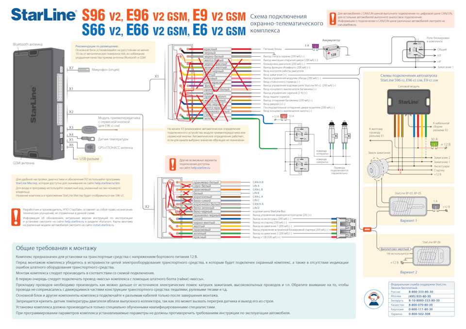 До 240 адресных извещателей, до 100 выходных реле. До 240 адресных извещателей, до 100 выходных реле. |
клапан honeywell | эссер |
| СОУЭ Variodyn D1 | honeywell 1450g | скачать |
| СОУЭ Variodyn D1 | Хановелл | honeywell esser |
| Система оповещения и музыкальной трансляции | Ханивелл | esser by honeywell |
| АРМ WinmagPlus | штрих кода honeywell | Создание и настройка сети Essernet |
| АРМ WinmagPlus | honeywell сканер штрих | Программирование адресных устройств |
| Программное обеспечение для диспетчеризации противопожарных систем Esser | сканер штрих кода honeywell | обавление (и удаление) пожарных извещателей (дымовых, тепловых, ручных) серии 9200, IQ8Quad, транспондеров в шлейфы сигнализации. |
| honeywell fk06 | инструкция honeywell | esser by honeywell официальный сайт |
| Программирование панели | honeywell voyager | variodyn d1 esser by honeywell |
| датчик honeywell | газовый клапан honeywell | 2xd250b усилитель esser by honeywell |
| редуктор honeywell | honeywell настройка | сигнализация esser |
Esser: 8000, 8008, IQ8Control-M(C), FlexEs Control. |
панель 8008 | esser пожарная сигнализация |
| honeywell драйвер | Контрольные панели серии 8000 и 8008 | esser пожарная сигнализация обучение |
| honeywell 808623 | транспондер 808623 | esser honeywell пожарная сигнализация сертификат мчс |
Автоматизация зданий (BMS/HVAC)
Автоматизация зданий начинается с наших инновационных систем управления зданиями, систем управления электроснабжением и систем управления для небольших зданий, которые позволяют создавать интеллектуальные здания, повышающие производительность сотрудников и оптимизирующие энергоэффективность и эффективность эксплуатации.
Видеонаблюдение
Для обеспечения безопасности жилых домов, административных зданий, складов, офисных помещений, коммерческих и промышленных объектов используются системы видеонаблюдения. С их помощью можно контролировать охраняемую территорию в режиме реального времени или проверяя записи за определенный период. Кроме того, закрепленные на видном месте камеры являются средством отпугивания грабителей, вандалов и прочих недоброжелателей.
Программное обеспечение (ПО)
Мозгом является центральный компьютер, имеющий комплекс соответствующего программного обеспечения. Центральный компьютер объединяет в единую сеть локальные контроллеры. Последние, в свою очередь, служат приемником для всевозможных датчиков и управляющим элементом для инженерного оборудования. Получая определенный сигнал от датчика, контроллер либо посылает требуемую обстоятельствами команду исполнительному устройству, либо отсылает сигнал диспетчеру, на центральный компьютер.
Система контроля и управления доступом и охранная сигнализация
Система контроля и управления доступом (СКУД) — это совокупность программных и технических средств, а также организационно-методических мероприятий, с помощью которых решается задача контроля и управления посещением охраняемого объекта.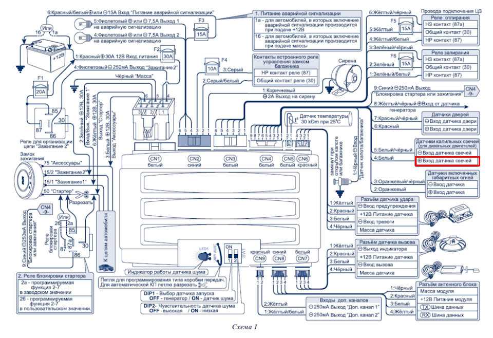
Система оповещения и управления эвакуацией
Принцип работы СОУЭ или принцип действия, принято называть алгоритмом работы. Алгоритм работы СОУЭ – это строгая последовательность действий оператора и самой аппаратуры систем пожарной безопасности. Аппаратура может работать в ручном, полуавтоматическом и автоматическом режимах. Нас больше интересует работа системы в автоматическом режиме.
Средства и системы охранно-пожарной сигнализации
Системы охранно-пожарной сигнализации предназначены для определения факта несанкционированного проникновения на охраняемый объект или появления признаков пожара, выдачи сигнала тревоги и включения исполнительных устройств (световых и звуковых оповещателей, реле и т. п.). Системы охранной и пожарной сигнализации по идеологии построения очень близки друг другу и на небольших объектах, как правило, бывают совмещены на базе единого контрольного блока – прибора приемно-контрольного (ППК) или контрольной панели (КП).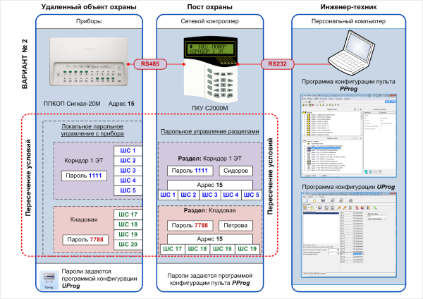
Инструкции
Для быстрого поиска документа воспользуйтесь формой поиска (нажмите кнопку F3)
Сборник инструкций по охране труда
для рабочих, выполняющих работы по монтажу систем автоматизации,
электротехнического оборудования, связи, пожарной и охранной
сигнализации
ИОТ 11233753-001-2007 (Скачать)
Инструкция по охране труда для организаторов производства
(работодателей) и ИТР при монтаже систем автоматизации,
электротехнического оборудования, связи, пожарной и охранной
сигнализации
ИОТ 11233753-002-2007 (Скачать)
ИДЕНТИФИКАЦИЯ ТВЕРДЫХ ВЕЩЕСТВ, МАТЕРИАЛОВ И СРЕДСТВ
ОГНЕЗАЩИТЫ ПРИ ИСПЫТАНИЯХ НА ПОЖАРНУЮ ОПАСНОСТЬ (Скачать)
Инструкция по организации обеспечения и эксплуатации средств
индивидуальной защиты персонала атомных станций при пожаре
1. 2.5.03.001.0032 – 2009 (Скачать)
ИНСТРУКЦИЯ ПО ОРГАНИЗАЦИИ БЕЗОПАСНОГО ПРОВЕДЕНИЯ
ОГНЕВЫХ РАБОТ В ЗДАНИЯХ И СООРУЖЕНИЯХ
ВЗРЫВОПОЖАРООПАСНЫХ ПРОИЗВОДСТВ
И ОБЪЕКТОВ ПО ХРАНЕНИЮ И ПЕРЕРАБОТКЕ ЗЕРНА (Скачать)
ИНСТРУКЦИЯ ПО ПРЕДУПРЕЖДЕНИЮ САМОВОЗГОРАНИЯ,
ТУШЕНИЮ И РАЗБОРКЕ ПОРОДНЫХ ОТВАЛОВ (Скачать)
ИНСТРУКЦИЯ ПО ОБЕСПЕЧЕНИЮ ПОЖАРНОЙ БЕЗОПАСНОСТИ
НА МОТОРВАГОННОМ ПОДВИЖНОМ СОСТАВЕ
ЦЛПР-11/17 (Скачать)
ИНСТРУКЦИЯ по организации деятельности объектовых
подразделений федеральной противопожарной службы
МЧС России по профилактике и (или) тушению пожаров (Скачать)
ИНСТРУКЦИЯ ПО ОРГАНИЗАЦИИ ЛИЦЕНЗИРОВАНИЯ ВИДОВ
ДЕЯТЕЛЬНОСТИ В ОБЛАСТИ ПОЖАРНОЙ БЕЗОПАСНОСТИ (Скачать)
ИНСТРУКЦИЯ ПО ОБЕСПЕЧЕНИЮ ПОЖАРНОЙ БЕЗОПАСНОСТИ
В ВАГОНАХ ПАССАЖИРСКИХ ПОЕЗДОВ (Скачать)
ИНСТРУКЦИЯ ПО ОРГАНИЗАЦИИ И ОСУЩЕСТВЛЕНИЮ ГОСУДАРСТВЕННОГО
ПОЖАРНОГО НАДЗОРА В РОССИЙСКОЙ ФЕДЕРАЦИИ (Скачать)
ИНСТРУКЦИЯ О ПОРЯДКЕ ПРИЕМА, РЕГИСТРАЦИИ И ПРОВЕРКИ
СООБЩЕНИЙ О ПРЕСТУПЛЕНИЯХ И ИНЫХ ПРОИСШЕСТВИЯХ В
ОРГАНАХ ГОСУДАРСТВЕННОЙ ПРОТИВОПОЖАРНОЙ СЛУЖБЫ
МИНИСТЕРСТВА РОССИЙСКОЙ ФЕДЕРАЦИИ ПО ДЕЛАМ
ГРАЖДАНСКОЙ ОБОРОНЫ, ЧРЕЗВЫЧАЙНЫМ СИТУАЦИЯМ
И ЛИКВИДАЦИИ ПОСЛЕДСТВИЙ СТИХИЙНЫХ БЕДСТВИЙ (Скачать)
ИНСТРУКЦИЯ О ПОРЯДКЕ ОТБОРА ГРАЖДАН НА СЛУЖБУ (РАБОТУ)
В ФЕДЕРАЛЬНУЮ ПРОТИВОПОЖАРНУЮ СЛУЖБ (Скачать)
ТИПОВАЯ ИНСТРУКЦИЯ по применению и техническому
обслуживанию огнетушителей на энергетических предприятиях (Скачать)
ИНСТРУКЦИЯ по проведению взрывных работ
при борьбе с лесными пожарами (Скачать)
ТИПОВАЯ ИНСТРУКЦИЯ по эксплуатации сетей противопожарного
водоснабжения на энергетических предприятиях (Скачать)
ИНСТРУКЦИЯ О ПОРЯДКЕ РАЗРАБОТКИ ОРГАНАМИ
ИСПОЛНИТЕЛЬНОЙ ВЛАСТИ СУБЪЕКТОВ РОССИЙСКОЙ ФЕДЕРАЦИИ,
ОРГАНАМИ МЕСТНОГО САМОУПРАВЛЕНИЯ И ОРГАНИЗАЦИЯМИ
НОРМАТИВНЫХ ДОКУМЕНТОВ ПО ПОЖАРНОЙ БЕЗОПАСНОСТИ,
ВВЕДЕНИЯ ИХ В ДЕЙСТВИЕ И ПРИМЕНЕНИЯ (Скачать)
ИНСТРУКЦИЯ О ПОРЯДКЕ СОГЛАСОВАНИЯ НОРМАТИВНЫХ
ДОКУМЕНТОВ, КОТОРЫЕ ПРИНИМАЮТСЯ ФЕДЕРАЛЬНЫМИ
ОРГАНАМИ ИСПОЛНИТЕЛЬНОЙ ВЛАСТИ И УСТАНАВЛИВАЮТ
ИЛИ ДОЛЖНЫ УСТАНАВЛИВАТЬ
ТРЕБОВАНИЯ ПОЖАРНОЙ БЕЗОПАСНОСТИ (Скачать)
ИНСТРУКЦИЯ ПО ОРГАНИЗАЦИИ И ПРОИЗВОДСТВУ СУДЕБНЫХ
ЭКСПЕРТИЗ В СУДЕБНО-ЭКСПЕРТНЫХ УЧРЕЖДЕНИЯХ И
ЭКСПЕРТНЫХ ПОДРАЗДЕЛЕНИЯХ ФЕДЕРАЛЬНОЙ
ПРОТИВОПОЖАРНОЙ СЛУЖБЫ (Скачать)
Типовая инструкция по тушению пожаров На
электроустановках АЭС концерна “Росэнергоатом” (Скачать)
ИНСТРУКЦИЯ ПО ОБЕСПЕЧЕНИЮ ПОЖАРНОЙ БЕЗОПАСНОСТИ
В ВАГОНАХ ПАССАЖИРСКИХ ПОЕЗДОВ
с дополнениями и изменениями, утвержденными указаниями МПС России
от 31. 03.2000 г. № Г-822у, 04.10.2001 № Е-1672у
ЦЛ-ЦУО-448 (Скачать)
ИНСТРУКЦИЯ ПО СЛУЖЕБНОМУ РАССЛЕДОВАНИЮ, УЧЕТУ
ПОЖАРОВ И ПОСЛЕДСТВИЙ ОТ НИХ НА ЖЕЛЕЗНОДОРОЖНОМ ТРАНСПОРТЕ
ЦУО-130 (Скачать)
ИНСТРУКЦИЯ ПО ВНЕДРЕНИЮ, ЭКСПЛУАТАЦИИ И ТЕХНИЧЕСКОМУ
ОБСЛУЖИВАНИЮ СРЕДСТВ ОХРАННО-ПОЖАРНОЙ АВТОМАТИКИ
НА ОБЪЕКТАХ ЖЕЛЕЗНОДОРОЖНОГО ТРАНСПОРТА РОССИЙСКОЙ ФЕДЕРАЦИИ
ЦУО-ЦШ-224 (Скачать)
ИНСТРУКЦИЯ ПО ОРГАНИЗАЦИИ ТЕХНИЧЕСКОЙ ЭКСПЛУАТАЦИИ
ТЕХНИЧЕСКИХСРЕДСТВ ОХРАНЫ НА ОБЪЕКТАХ,
ОХРАНЯЕМЫХ ПОДРАЗДЕЛЕНИЯМИ МИЛИЦИИ ВНЕВЕДОМСТВЕННОЙ
ОХРАНЫ ПРИ ОРГАНАХВНУТРЕННИХ ДЕЛ РОССИЙСКОЙ ФЕДЕРАЦИИ (Скачать)
HONEYWELL XLS80E РУКОВОДСТВО Скачать Pdf
Содержание
3
-
страница
из
138 - Содержание
- Оглавление
- Закладки
Advertisement
Table of Contents
-
Table of Contents
-
1 Introduction
-
Associated Documents
-
System Design and Planning
-
Glossary of Icons
-
Software Version Number
-
Функции EN54
-
Вспомогательные функции
-
-
2 Power On/Start Up
-
3 Обзор конфигурации панели
-
Где для доступа к действиям конфигурации
- .
-
Жидкокристаллический дисплей
-
-
Использование средства автономной поддержки
-
Коды доступа
-
Learn Devices on Loops
-
Configure Group of Devices
-
Configure Individual Device
-
Text Editing
-
Control Matrix
-
Time-Of-Day
-
Setting the Clock
-
Настройки панели
-
Системная сеть
-
Задержки
-
Конфигурация виртуальной точки

4 The Display – Tabs, Events and Menus
-
Introduction
-
Status: NORMAL
-
Events
-
-
Event Displays
-
Menu Displays
-
Для отображения меню пользователя
-
Для навигации по меню
-
Структура меню
-
5 Конфигурация устройства Loop
-
Настройка отдельного устройства
-
Выберите устройство
-
Конфигурация устройства изменений10
-
Multi, MCS & Gas Sensitivities
-
Multi, MCS & GASE Sensitivities
- 9
-
– MCS & GAS Sensitivities10
- 333333300
-
– MCS & GASE Sensitivities10
- 3333300
-
.
-
-
Настройка группы устройств
-
Изучение устройств в петлях
-
Запуск процедуры
-
Запуск в режиме автоматической освоения
-
Запустить в ручном режиме обучения
-
Сообщения об ошибках
-
Конец процесса обучения
-
-
Зона изменения
- 17

.
-
Кнопки редактирования текста
-
Набор символов
-
Редактирование текста зоны
-
Редактирование текста панели
0017
-
7 Control Matrix
-
Introduction
-
EN54 Requirements
-
-
Input Categories
-
Output Categories
-
Output Modes
-
Review/Edit Control Matrix
-
Просмотр записей
-
Редактирование записей
-
-
Определение записи контрольной матрицы
-
Input Definitions
-
Output Definitions
-
Completion of New Entry
-
-
Disablement/Enablement Function
-
Extinguishing System Function
-
Types of Control Matrix Entry
-
Minimum Configuration
-
Выбор устройства
-
Опции HOLD
-
-
Логическая операция с флагами передачи
-
Example Logic Operations
-
-
Print Control Matrix
-
-
8 Change Passcode
-
Introduction
-
How to Change a Passcode
-
-
9 Time-Of- Программирование дня
-
Редактирование программы времени суток
-
Ручное управление
-
ОТКЛЮЧЕНИЕ и РАЗРЕШЕНИЕ Переопределение
-
Multi Thermal-Only Mode
-
Ссылка на Day/Night Switch
-
-
10 Установка часов
-
11 Панельные настройки
-
ВНЕШНЯЯ БУЗЕР.
-
Количество шлейфов на панели
-
Режимы импульсного звукового оповещателя
-
Параметры проверки проходом (Mcp/звуковой оповещатель)
-
Опции автоматического тестирования
-
Опции отключения
-
Опции петли
-
Функции панели
-
Доступ к входному регистрации01114
-
ОБЩЕСТВЕННЫЙ НЕОБ Задержки неисправности сети/блока питания
-
Продолжительность включения подсветки ЖК-дисплея
-
Пустые строки между напечатанными событиями
-
Настройка изолированного порта RS232
-
Diagnostic RS232 Port Set-Up
-
Remote Fire Output Options
-
Day/Night Modes Configuration
-
Extinguishing System
-
Alarm Coincidence
-
Network Settings
-
Время проверки теплового аварийного сигнала
-
-
12 Меню пользователя на уровне 3 Доступ
-
Тесты управляющих выходов
-
CMX Модули
-
Локальные цепки зондота
-
Цепи реле
-
Virtual Outpute
-
Sounders и BOOSTERS
-
-
.
-
Меню сканирования ненастроенных устройств
-
Режим ввода в эксплуатацию для датчиков MCS
-
-
13 Чувствительность и задержка тревоги
-
Рекомендации
-
.
-
Количество станций в сети
-
Количество зон в сети
-
Распределение информации с помощью сети
-
-
Процедуры конфигурации сети
-
Станция Тип
-
Эта панель
-
Associate Receaters
-
Associate Receaters с панелью
-
.
Конфигурация
-
-
15 Конфигурация виртуальной точки
-
Виртуальные точки вывода
-
Виртуальные точки входа
-
Виртуальный звуковой оповещатель
-
XLS80e
Конфигурация панели
Руководство
Март 2007 г., выпуск 9
Содержание
Предыдущая страница
Следующая страница
Содержание
Краткое содержание для Honeywell XLS80e
Панель управления
XLS80e | Панели управления пожарной сигнализацией | Панели управления огнем | Контроллеры и панели управления | Панели управления пожарной сигнализацией
Панели управления пожарной сигнализацией
- Обзор
- Артикул
Обзор
Панели управления XLS80e от Honeywell доступны в версиях с числом контуров от 2 до 8.
Это одни из немногих на рынке панелей, которые соответствуют стандартам и при этом обеспечивают управление более чем 512 устройствами. Плата Enhanced Loop Interface Board (ELIB) обеспечивает многопроцессорное управление для обеспечения до 8 контуров обнаружения и звуковых оповещателей с питанием от одного контроллера. Ключевым преимуществом этой системы является функциональность, которую можно обеспечить при подключении к Enterprise Building Integrator, EBI.Особенности и преимущества:
- Полная интеграция в EBI
- Платы Enhanced Loop Board обеспечивают подключение более 512 устройств на панель управления оборудование, лазерный датчик обнаружения точек, звуковые оповещатели с питанием от контура, режим ожидания 24 и 72 часа
- Прямое последовательное подключение к XLPAVA – системе оповещения и голосового оповещения
- Паран -коллеги или главные рабские сети
Сертификации:
- LPCB
Сорт
Документ.
-

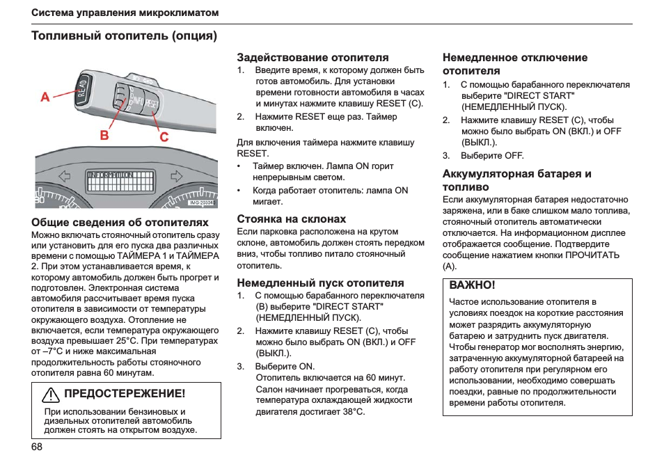
 Конфигурация
 Это одни из немногих на рынке панелей, которые соответствуют стандартам и при этом обеспечивают управление более чем 512 устройствами. Плата Enhanced Loop Interface Board (ELIB) обеспечивает многопроцессорное управление для обеспечения до 8 контуров обнаружения и звуковых оповещателей с питанием от одного контроллера. Ключевым преимуществом этой системы является функциональность, которую можно обеспечить при подключении к Enterprise Building Integrator, EBI.
Download any manual ! 24 hours access to millions of manuals
Operating instructions, user manual, owner’s manual, installation manual, workshop manual, repair manual, service manual, illustrated parts list, electric schematics, electronic schematics….
Any manual costs 29.90 EUR in addition to non-refundable 9.90 EUR flat rate (mandatory research fees to create an order)
Home — Advanced search — How it works — All brands — All appliances — Special selection — Download (orders)
Terms of service — Contact © 2004-2023 Assistance Network Inc.
Recent search for :
PANASONIC PHONE TG23
VAILLANT VMW ES 242
SINGER 732 71
SINGER NO MODELE 9020915
MOTOROLA GDLN800
VAILLANT VMW ES 242
PANASONIC NV-H70
MIELE T369C
SAMSUNG HTTZ315T
SINGER MADAM489
SINGER 6790
SINGER MEMO-MATIC 2310 UNION ALL SELECT NULLNULLNULLNULLNULLNULLNULLNULLNULLNULL— BPKL
SAMSUNG DF8160S S10357
DEVILLE CLEO
JANOME 671
BEKO WMB7612
SINGER CHANTAL THOMA
SAMSUNG LA32C450 SERVICE53
ARISTON LD87
SAMSUNG LE27T61E
MOTOROLA VIP2262E
BOSCH SMV53M40EU21
DAIKIN MY56DA
KUBOTA KC 4200O
ALTO COMPACT 1050 X TRA
AVIDSEN 105125
KUBOTA GH340 SERVICE MANUAL
PANASONIC KX TS580
BROTHER XL2600I
DAIKIN ARC448A1
SAMSUNG DF8160S S62
SIEMENS FM726
SINGER 14J33470
SONY AR269N
WHIRLPOOL AVM 551 IX
HOWTEK (1) HOWDENS (5) HOTPOINT ARISTON (15) HOTPOINT (95) HORSTMANN (4) HORMANN (13) HORIZON (35) HORIBA (2) HOOVER (206) HONEYWELL (132) HONDA (587) HOMETECH (1) HOMEMAKER (7) HOMELITE (86) HOMEIMAGE (1) HOME THEATER MASTER (1) HOME (2) HOLZINGER (6) HOLUX (1) HOLMAN (1) HOLLAND (2) HOFMANN (51) HOFMAN (1) HOERMANN (HORMANN) (24) HOERMANN (2) HOBART (48)