
-
Страница 1
Industrial Measur ement and Control HC900 Hybrid Contr oller Installation and User Guide Doc. No.: 51-52-25-107 Revision: 5 Date: 9/03[…]
-
Страница 2
ii HC900 Hybrid Controller Installation and User Guide Revision 5 9/03 Notices and Trademarks Copyright 2003 by Honeywell Revision 5 Sept. 2003 Warranty/Remedy Honeywell warrants goods of its manufacture as being free of defective materials and faulty workmanship. Contact your local sales office for warranty information. If warranted goods are retu[…]
-
Страница 3
Revision 5 HC900 Hybrid Controller Installation and User Guide iii 9/03 About This Document Abstract This docum ent provides descr iptions and pro cedures for the instal lation, operation a nd maintenance of the HC900 Hybrid C ontroller hard ware. References The following list identifies all documents that may be sources of refere nce for material […]
-
Страница 4
iv HC900 Hybrid Controller Installation and User Guide Revision 5 9/03 Symbol Definitions The following table lists those symbols that may be us ed in this document and on the product to denote certain conditions. Symbol Definition This DANGER symbol indicates an imminently hazardous situation, which, if not avoided, will result in death or serious[…]
-
Страница 5
Revision 5 HC900 Hybrid Controller Installation and User Guide v 9/03 Contents Introducti on ………………………………………………………………………………… 1 Purpose ………………………………………………………………………………………………………… 1 Functional Description …….[…]
-
Страница 6
vi HC900 Hybrid Controller Installation and User Guide Revision 5 9/03 Communications In stallation ……………………………………………………….. 85 Overvi ew ……………………………………………………………………………………………………… 85 Connecting the HC900 Controller to a PC with the H[…]
-
Страница 7
Revision 5 HC900 Hybrid Controller Installation and User Guide vii 9/03 DC Input M odule …………………………………………………………………………………………. 165 AC Input Module …………………………………………………………………………………………. 166 Features Common to a ll Outpu[…]
-
Страница 8
viii HC900 Hybrid Controller Installation and User Guide Revision 5 9/03 Tables Table 1 – Descriptions of Major Com ponents (Figure 3) ……………………………………………………………….. ……………….. 7 Table 2 Simultaneous seri al port conf igurations ………………………………………………………..[…]
-
Страница 9
Revision 5 HC900 Hybrid Controller Installation and User Guide ix 9/03 Figures Figure 1 – Small HC900 Controller Conf iguration ……………………………………………………………………. ………………….. 2 Figure 2 – Expanded HC 900 Controller Configur ation (C50 CPU only) ……………………………………..[…]
-
Страница 10
x HC900 Hybrid Controller Installation and User Guide Revision 5 9/03 Figure 54 — Pathways for Up load/Dow nload Transactions ……………………………………………………………….. ………….. 114 Figure 55 — LE D In dicators ………………………………………………………………………………………..[…]
-
Страница 11
Revision 5 HC900 Hybrid Controller Installation and User Guide 1 9/03 Introduction Purpose This publication describes the Honeywell HC900 Hybrid Contro ller, and facilitates its installation, operation, and maintenan ce. This publication includes the following sections. Section Title Section Content Introduction Describes the c ontent and purpos e […]
-
Страница 12
Introduction — Functional Description 2 HC900 Hybrid Controller Installation and User Guide Revision 5 9/03 Functional Description The Honeywel l HC900 Hybrid C ontroller is an integrated loop and logic controller that is design ed specifically for small- and medium -scale unit operations It comprises a set of hardware an d software m odules that c[…]
-
Страница 13
Introduction — Feature Summary Revision 5 HC900 Hybrid Controller Installation and User Guide 3 9/03 The HC900 Controller design enables users and OEMs who are adept in system integration to assemble a system t hat fits a broad range of requirem ents. Any confi guration can be readily modifi ed or expanded as requirements dictate. In initial config[…]
-
Страница 14
Introduction — Feature Summary 4 HC900 Hybrid Controller Installation and User Guide Revision 5 9/03 Control Functions • Comprehensive set of Function Blocks; in cludes: − PID: Model C50 — up to 32 loops Model C30 – up to 8 loops − Setpoint P rogrammers: up t o 8; SP Profiles: pool of 99, wit h up to 50 Se gments/Profile; SP Schedulers: 1 o[…]
-
Страница 15
Revision 5 HC900 Hybrid Controller Installation and User Guide 5 9/03 Components and Architecture Overview This section pr ovides a descript ion of each of the major com ponents that can be incl uded in an HC900 Controller physical configura tion, and indic ates some of th e methods by whic h they can be com bined. Components The Honeywell HC900 Hy[…]
-
Страница 16
Components and Architecture — Components 6 HC900 Hybrid Controller Installation and User Guide Revision 5 9/03 Figure 3 — Configuration with Multiple Controllers[…]
-
Страница 17
Components and Architecture — Components Revision 5 HC900 Hybrid Controller Installation and User Guide 7 9/03 Table 1 – Descriptions of Major Components (Figure 3) Key No. Component Name Description Source 1 Controller (Local) Rack Includes: Rack, Power Supply, Controller Modul e, and I/O modules Honeyw ell 2 I/O Expansion Rack (C50 CPU only) (O[…]
-
Страница 18
Components and Architecture — Hard ware Components 8 HC900 Hybrid Controller Installation and User Guide Revision 5 9/03 Hardware Components This section contains general descriptions of each of the m ajor component s of the HC900 system. For environm ental specifications, refe r to the secti on on Pre-Instal lation Planning. HC900 Controller Rack […]
-
Страница 19
Components and Architecture — Hard ware Components Revision 5 HC900 Hybrid Controller Installation and User Guide 9 9/03 Rack Options Racks are availa ble in 4-slot, 8-sl ot, and 12-Slot versions. Racks are interc hangeable between the Controller rack and an IO expansion rack (C 50 CPU only) , and all three vers ions shown in Fi gure 6 are availabl[…]
-
Страница 20
Components and Architecture — Hard ware Components 10 HC900 Hybrid Controller Installation and User Guide Revision 5 9/03 Controller Module The Controller Module is shown in Figure 8 with the hinged protective door open. Features at the front of the Controller Module in clude: 1 — a lithium battery (beneath cover), which is readily accessible for f[…]
-
Страница 21
Components and Architecture — Hard ware Components Revision 5 HC900 Hybrid Controller Installation and User Guide 11 9/03 Input/Output Modules Eight input/ output types are available: • Analog − Universal Anal og Input, 8-poi nt − Analog Out put, 4-point • Digital − 120/240 Vac inp ut, 16-point − 24 Vdc inp ut, 16-point − Contact inp […]
-
Страница 22
Components and Architecture — Hard ware Components 12 HC900 Hybrid Controller Installation and User Guide Revision 5 9/03 Personal Computer A Personal C omputer is re quired for creating t he contro l and data acquisition strategy (configuration file) that runs in the controller, us ing the Hybrid Control Designer confi guration software . The PC c[…]
-
Страница 23
Components and Architecture — Et hernet Dev ices/Considerations Revision 5 HC900 Hybrid Controller Installation and User Guide 13 9/03 Ethernet Devices/Considerations Ethernet devic e requirements va ry with specific appli cations. Regarding intended use, however, they fall into two categories: • Component s of the Ethernet O pen Connectivity Net[…]
-
Страница 24
Components and Architecture — Et hernet Dev ices/Considerations 14 HC900 Hybrid Controller Installation and User Guide Revision 5 9/03 The Ethernet Hu bs used in the I/ O expansion networ k (C50 CPU only)a re available from Honeywell. I/O implementation requirements include: • Constructing a configu ration file, and loading it into the Controller[…]
-
Страница 25
Components and Architecture — Et hernet Dev ices/Considerations Revision 5 HC900 Hybrid Controller Installation and User Guide 15 9/03 Implem enting peer-to-peer c ommunications involves: • Interconnecti ng controlle rs with Ethernet m edia and networki ng devices (cables, hubs, switches, etc) • Configuration (via Hybrid Control Designer): − […]
-
Страница 26
Components and Architecture — Et hernet Dev ices/Considerations 16 HC900 Hybrid Controller Installation and User Guide Revision 5 9/03 Note: PDE c ommunications, di scussed previ ously, do not use t he PC host connectio n sockets. PDE communications are separate from (and are transmitted concurrent with) PC host-to-controller communicat ions. The P[…]
-
Страница 27
Components and Architecture — Et hernet Dev ices/Considerations Revision 5 HC900 Hybrid Controller Installation and User Guide 17 9/03 HMI software available for use with the HC900 Controller includes, but is not necessarily limited to the packages whos e descriptions foll ow. • available from Honeywell − PlantScape SCADA or Vista Software, whi[…]
-
Страница 28
Components and Architecture — Et hernet Dev ices/Considerations 18 HC900 Hybrid Controller Installation and User Guide Revision 5 9/03 E-Mail Communications The HC900 Controller includes e-mail software that enables communication of Alarms and Even ts to up to three Internet addresses. Implementing this feature consists of: • Using the Hybrid Con[…]
-
Страница 29
Components and Architecture — Serial Ports (RS23 2 and RS485) Revision 5 HC900 Hybrid Controller Installation and User Guide 19 9/03 Serial Ports (RS232 and RS485) Overvie w • Ports configurab le as ELN, Modbus RTU or Modbus TCP protocol. • Controller ca n act as Modbus master or slave thr ough either port . • Controller can be ma ster to sla[…]
-
Страница 30
Components and Architecture — Serial Ports (RS23 2 and RS485) 20 HC900 Hybrid Controller Installation and User Guide Revision 5 9/03 RS-232 RS-232 ELN P r otoco l ELN Protocol 2000 Ft 2000 Ft ELN and ELN ELN proto col ELN protocol RS 485 RS 485 1 RS-232 RS-232 RS 485 RS 485 ELN protocol ELN protocol Modbus Modbus Slave Slave Protocol Protocol 2000 […]
-
Страница 31
Components and Architecture — Serial Ports (RS23 2 and RS485) Revision 5 HC900 Hybrid Controller Installation and User Guide 21 9/03 A L M I % Honeywell RS-232 RS-232 RS 485 RS 485 Modb us Modbus Ma ste r Master Protocol Protocol Modb us Modbus Sl ave Slave Protoc ol Protocol 2000 Ft 2000 Ft Modbus Sl ave and Modbus Maste r 3rd Party HM I Modbus M […]
-
Страница 32
Components and Architecture — Net working Basics Reference 22 HC900 Hybrid Controller Installation and User Guide Revision 5 9/03 See also Refer to Com munications In stallation on pa ge 85 for detail s on communicat ions. Networking Basics Reference The followin g information pr ovides a basic refe rence for identifyin g and applying networking co[…]
-
Страница 33
Components and Architecture — Net working Basics Reference Revision 5 HC900 Hybrid Controller Installation and User Guide 23 9/03 operates in La yer 3, IP opera tes at Layer 2, and Ethe rnet itself includes protocols that o perate at Layers 1 and 2.[…]
-
Страница 34
Components and Architecture — Net working Basics Reference 24 HC900 Hybrid Controller Installation and User Guide Revision 5 9/03 Characteristics of Net w orking Dev ices Table 2 summarizes the characteristics of a set of «gen eric» netw orking devices. The information i n this table is intende d to provide a basic overview of each t ype […]
-
Страница 35
Components and Architecture — Net working Basics Reference Revision 5 HC900 Hybrid Controller Installation and User Guide 25 9/03 Table 3 — Open System Interc onnection Model Layer Number .. Name Function Components reside in: Protocols (examples) Network components affected (examples) 7. Application Identifies communication s partners, quality of […]
-
Страница 36
Components and Architecture — Net working Basics Reference 26 HC900 Hybrid Controller Installation and User Guide Revision 5 9/03 Table 4 — Networking Device Types Network Device Description Notes Hub A Hub is so called because a diagram of its connections re sembles a hub of a s poked wheel. Characteristics: Echoes a message on any port to all oth[…]
-
Страница 37
Components and Architecture — Net working Basics Reference Revision 5 HC900 Hybrid Controller Installation and User Guide 27 9/03 Table 5- Glossary of Networking Terms Name/Acronym Name/Definiti on Comments 10Base-Tx Specification for 10mbps carried over twisted-pair cable. In the name 10 Base-T, the “10” refers to 1 0 Mbps transmission speed, […]
-
Страница 38
Components and Architecture — Net working Basics Reference 28 HC900 Hybrid Controller Installation and User Guide Revision 5 9/03 Name/Acronym Name/Definiti on Comments Collision Simultaneous transm ission of two no des on the same channel. Collisions can be reduced (and network capacity increased) by use of Switc hes, wh ich partition and isolate […]
-
Страница 39
Components and Architecture — Net working Basics Reference Revision 5 HC900 Hybrid Controller Installation and User Guide 29 9/03 Name/Acronym Name/Definiti on Comments Domain Nam e A text nam e, appended to the Host name. Identifies a node as a m ember of a domain. DS1, DS3 Dedicated leased telephone lines DS1 (T-1) carries 1.544 Mbp s, DS3 (T-3) […]
-
Страница 40
Components and Architecture — Net working Basics Reference 30 HC900 Hybrid Controller Installation and User Guide Revision 5 9/03 Name/Acronym Name/Definiti on Comments IP Address Internet Protocol A ddress Guaranteed u nique address, assi gned by the Internet Corp oration for Assign ed Names and Numbers (ICANN ). IP address includes four “octets[…]
-
Страница 41
Components and Architecture — Net working Basics Reference Revision 5 HC900 Hybrid Controller Installation and User Guide 31 9/03 Name/Acronym Name/Definiti on Comments Modbus TCP/ IP Variant of M odbus protocol Modbus TCP/I P is a derivative o f related Modbus protocol used with RS-232 or RS-4 85 data acquisition and superv isory structures. Basic[…]
-
Страница 42
Components and Architecture — Net working Basics Reference 32 HC900 Hybrid Controller Installation and User Guide Revision 5 9/03 Name/Acronym Name/Definiti on Comments Node Any intelligent device that includes a hard ware address that can be recognized by other networ k devices. The “node” termino logy is sometimes limite d to computing device[…]
-
Страница 43
Components and Architecture — Net working Basics Reference Revision 5 HC900 Hybrid Controller Installation and User Guide 33 9/03 Name/Acronym Name/Definiti on Comments RJ-45 Style of co nnector at end of Ethernet twisted-pair cable Router A device that is capa ble of filtering messages based on IP addresses. Routers diffe r from Bridges a nd Switc[…]
-
Страница 44
Components and Architecture — Net working Basics Reference 34 HC900 Hybrid Controller Installation and User Guide Revision 5 9/03 Name/Acronym Name/Definiti on Comments Telnet Application that provides a terminal interface between hosts usin g TCP/IP. Telnet defines a protocol that al lows a remote terminal session to be established with an Interne[…]
-
Страница 45
Pre-Installation Planning — Networkin g Basics Reference Revision 5 HC900 Hybrid Controller Installation and User Guide 35 9/03[…]
-
Страница 46
Pre-Installation Planning — Overview 36 HC900 Hybrid Controller Installation and User Guide Revision 5 9/03 Pre-Installation Planning Overview Methodical pre-planning of an installatio n will precl ude false starts and errors that can cause co stly hardware re-co nfiguration and/or poor system performance. Some consi derations in p re-installation […]
-
Страница 47
Pre-Installation Planning — Power Supply Selection Revision 5 HC900 Hybrid Controller Installation and User Guide 37 9/03 Power Supply Selection To determine which power supply to use, calculate power requirements below. ATTENTION Using inadequate power supply will cause the controller to cycle power on and off. Enter quantity of each modul e type […]
-
Страница 48
Pre-Installation Planning — Environment 38 HC900 Hybrid Controller Installation and User Guide Revision 5 9/03 Environment Environmental Operating Limits The environmental conditions requ ired for operating the HC900 Hybrid Controller are listed Table 6. Table 6 — Operating Limits and Installation Guidelines Condition Specifications Ambient Tempera[…]
-
Страница 49
Pre-Installation Planning — Or ientation of Rac k Mounting Revision 5 HC900 Hybrid Controller Installation and User Guide 39 9/03 The HC900 C ontroller must be mounted in s uitable equipment enclosures. T hat is, all com ponents such as the Controller rack, IO Expander R acks, and the Operator Interface m a nufactured by Honey well must be mounted […]
-
Страница 50
Pre-Installation Planning — Heat Rise De-r ating 40 HC900 Hybrid Controller Installation and User Guide Revision 5 9/03 Figure 18 — AC Input Module de-Rating Figure 19 — Po w er Supply De-rating[…]
-
Страница 51
Pre-Installation Planning — Equi pm ent Placement Considerations Revision 5 HC900 Hybrid Controller Installation and User Guide 41 9/03 Equipment Placement Considerations Factors that determine where equipment should be located within the site include at least the following: • Environmental conditions (see above). • Wiring/cabling characteristi[…]
-
Страница 52
Pre-Installation Planning — Electrical Co nsiderations 42 HC900 Hybrid Controller Installation and User Guide Revision 5 9/03 Controller rack connected via two Ethernet Hubs to I/O expansion racks (C50 CPU only) Length of Ethernet cable, each segment: 328 feet (100 meters). Note: The use of Ethernet ca bles in excess of 100 m eters and/or devices o[…]
-
Страница 53
Pre-Installation Planning — Electrical Co nsiderations Revision 5 HC900 Hybrid Controller Installation and User Guide 43 9/03 Figure 20 — Cabinet Wiring, Single Chassis Figure 21 — Cabinet Wiring, Multiple Chassis[…]
-
Страница 54
Pre-Installation Planning — Electrical Co nsiderations 44 HC900 Hybrid Controller Installation and User Guide Revision 5 9/03 CE Conformity Electrical noise produces undesirable effect s in measurements and control circuits. Digital equipment is especially sensitive to the e ffects of electrical noise. You should use the following methods to red uc[…]
-
Страница 55
Pre-Installation Planning — Electrical Co nsiderations Revision 5 HC900 Hybrid Controller Installation and User Guide 45 9/03 System Monitor Function Blocks The HC900 C ontroller include s function blocks t hat enable the user t o monitor the status of system functions. When constructi ng a control confi guration, add t he following f unction block[…]
-
Страница 56
Pre-Installation Planning — Electrical Co nsiderations 46 HC900 Hybrid Controller Installation and User Guide Revision 5 9/03 Figure 22 — Master Control Relay Wiring Example[…]
-
Страница 57
Pre-Installation Planning — Electrical Co nsiderations Revision 5 HC900 Hybrid Controller Installation and User Guide 47 9/03 Rack Dimensions Rack dimensions, including overall dimensions and patterns for drilling holes for mounting, are give n in Figure 23. Vertical spacing of racks, which is required for rack ventilation and for routing wires, is[…]
-
Страница 58
Pre-Installation Planning — Electrical Co nsiderations 48 HC900 Hybrid Controller Installation and User Guide Revision 5 9/03 Site Plan Documentation Documenti ng the plan for inst alling a process co ntrol structure yiel ds significant benefi ts: • The task of instal lation plann ing itself is facilitated. • Properly organized docum entation g[…]
-
Страница 59
Installation Guide — Overview Revision 5 HC900 Hybrid Controller Installation and User Guide 49 9/03 Installation Guide Overview This section c ontains procedures for installing one or more HC900 C ontrollers. It is recommended t hat the Site Plan Documentation, completed as a part of Pre -Installati on Planning, is used as a primary data source an[…]
-
Страница 60
Installation Guide — Overview 50 HC900 Hybrid Controller Installation and User Guide Revision 5 9/03 Table 10 — Site and Equipment Preparation Step Procedure Refer ence 1 Referring to Site Plannin g Documentation, ensure that sufficient numbers of the following items are on hand: • Racks (4-, 8- and 12-slot) • Power Supplies (1 per rack) • Co[…]
-
Страница 61
Installation Guide — Overview Revision 5 HC900 Hybrid Controller Installation and User Guide 51 9/03 Step Procedure Refer ence 4 Install (or verify co rrect installa tion of): • External disconnect s witches • Fuses at the power source associated with input sensor or output devices for I/O modules. I/O Module Installation section in this manual[…]
-
Страница 62
Installation Guide — Overview 52 HC900 Hybrid Controller Installation and User Guide Revision 5 9/03 Table 11 — Install HC900 Controller Components Step Procedure Comments/Referen ces Mount the Controller Rack in the enclosure as follows. • Using the diagram below as a guide, mark the locations for rack mounting in the enclosure for the top holes[…]
-
Страница 63
Installation Guide — Overview Revision 5 HC900 Hybrid Controller Installation and User Guide 53 9/03 Step Procedure Comments/Referen ces 2 Aluminum grounding bars for I/O module wiri ng are optional. T hey can be mounted at t op, at bottom, or at top and botto m of the rack, as indicated at right. If grounding bars ar e included, attach them with t[…]
-
Страница 64
Installation Guide — Overview 54 HC900 Hybrid Controller Installation and User Guide Revision 5 9/03 Step Procedure Comments/Referen ces Hazardous Voltage • Ensure that wiring to the Power Supply is di sconnected fro m the site AC source before installing wiring. • Do not remove Yellow/Green wire from groundi ng stud on the power supply. Failur[…]
-
Страница 65
Installation Guide — Overview Revision 5 HC900 Hybrid Controller Installation and User Guide 55 9/03 Step Procedure Comments/Referen ces 6 Ensure that jumpers are installed in J9 o n the Controlle r Module as shown at right. 7 Ensure that AC power to the rack is disconnected. Carefully place the Controlle r Module in the local rack, immediately to […]
-
Страница 66
Installation Guide — Overview 56 HC900 Hybrid Controller Installation and User Guide Revision 5 9/03 Step Procedure Comments/Referen ces 8 For each I/O e xpansion rack (C50 CP U only), set the Scanner Module jumpers to the appropriate Rack Address as shown at right. Repeat steps 1t hrough 5 for each I/O expansion rack (C50 CPU only). Then, for each[…]
-
Страница 67
Revision 5 HC900 Hybrid Controller Installation and User Guide 57 9/03 I/O Module Installation and Wiring Overview This section c ontains descriptions of and procedu res for install ing I/O Modules in c ontroller racks a nd in I/O expansi on racks(C50 C PU only). Module Placement in Racks Each input or output module i s placed in an I/O slot in a r[…]
-
Страница 68
I/O Module Installation and Wiring — Module Placement in Racks 58 HC900 Hybrid Controller Installation and User Guide Revision 5 9/03 Terminal Block Styles The terminal block is available in the barrier style, shown at left in Figure 26, and the Euro style, shown at right. Both styles of t erminal blocks ha ve an embossed n umbering «key»[…]
-
Страница 69
I/O Module Installation and Wiring — Remote Termination Panel (RT P) Revision 5 HC900 Hybrid Controller Installation and User Guide 59 9/03 Remote Termination Panel (RTP) The optional Remote Termination Panel (RTP) provides an easy way to connect the HC900 controller to the field wiring. The RTP integrates som e of the typi cal externally connected[…]
-
Страница 70
I/O Module Installation and Wiring — Terminal Block-to-Field (Signal) Wiring 60 HC900 Hybrid Controller Installation and User Guide Revision 5 9/03 Signal Grounding The shield for each input sh ould be grounded at the grounding bar (optional) at the top or botto m of each rack as indicated in Figure 27. For low -frequency noise rejection, I/O wi ri[…]
-
Страница 71
I/O Module Installation and Wiring — Terminal Block-to-Field (Signal) Wiring Revision 5 HC900 Hybrid Controller Installation and User Guide 61 9/03 Terminal Block Jumper Combs Two styles of terminal block jumper combs are availabl e for use with the barrier-style terminal blo cks: ten- position and two position. The ten-posi tion jumpers are used w[…]
-
Страница 72
I/O Module Installation and Wiring — Remo val and Insertion Under Power (RIUP) 62 HC900 Hybrid Controller Installation and User Guide Revision 5 9/03 Removal and Insertion Under Power (RIUP) Read and un derstand all of th e following inform ation regardin g RIUP before at tempting to rem ove and/or replace any I/O module, pa rticul arly in a system[…]
-
Страница 73
I/O Module Installation and Wiring — I/O Installation Procedures Revision 5 HC900 Hybrid Controller Installation and User Guide 63 9/03 I/O Installation Procedures Table 14 — Connect Input/Output Wiring Step Procedure Co mments Refer ence 1 Using Rack #, Slot #, Channel # data from a Hybrid C ontrol Designe r report and/or from document ation aids […]
-
Страница 74
I/O Module Installation and Wiring — I/O Installation Procedures 64 HC900 Hybrid Controller Installation and User Guide Revision 5 9/03 Step Procedure Co mments Refer ence 4 For each configur ed and labeled I/O M odule, break off the «key-tabs» in the pattern that identifies each module ty pe. (For a d iagr am of each key-tab pattern, use[…]
-
Страница 75
I/O Module Installation and Wiring — I/O Installation Procedures Revision 5 HC900 Hybrid Controller Installation and User Guide 65 9/03 Step Procedure Co mments Refer ence NOTE: In the diagram below, t he wh ite cut-outs represent the cu t-outs on the modules that accommodate tabs on the Terminal Block. Th at is, all key-tabs that line up with the […]
-
Страница 76
I/O Module Installation and Wiring — I/O Installation Procedures 66 HC900 Hybrid Controller Installation and User Guide Revision 5 9/03 Step Procedure Co mments Refer ence 5 Using the following reference item s: • Hybrid Control Designer data • Documentation Aids from Appendix A • Labels in I/O Terminal Block assemblies • Wiring diagram s g[…]
-
Страница 77
I/O Module Installation and Wiring — I/O Installation Procedures Revision 5 HC900 Hybrid Controller Installation and User Guide 67 9/03 Step Procedure Co mments Refer ence 7 Connect wire shield to groundin g bars on top and/or bott om of the Rack. (Refer to Signal Grounding, at the beginning of this section, for suggestions and recommendati ons.) 8[…]
-
Страница 78
I/O Module Installation and Wiring — I/O Terminal Block Wiring Diagrams 68 HC900 Hybrid Controller Installation and User Guide Revision 5 9/03 I/O Terminal Block Wiring Diagrams Universal Analog Input Module Wiring The Universal Analog Input Module has eight inputs, whi ch can include any comb ination of the following input types: RTD, TC, Ohms, Mi[…]
-
Страница 79
I/O Module Installation and Wiring — I/O Terminal Block Wiring Diagrams Revision 5 HC900 Hybrid Controller Installation and User Guide 69 9/03 Figure 31 — Universal Anal og Input Wiring Diagram Figure 32 — Examples of RTD Input Wiring[…]
-
Страница 80
I/O Module Installation and Wiring — I/O Terminal Block Wiring Diagrams 70 HC900 Hybrid Controller Installation and User Guide Revision 5 9/03 Figure 33 — Analog Input Wiring — Eight TCs Figure 34 — Analog Input Wiring — Eight Resistanc e Inputs[…]
-
Страница 81
I/O Module Installation and Wiring — I/O Terminal Block Wiring Diagrams Revision 5 HC900 Hybrid Controller Installation and User Guide 71 9/03 Figure 35 — Analog Input Wiring — Eight RTDs I RTD 1 & 2 I RTD 1 & 2 I 3 RTD & 4 I 3 RTD & 4 I 5 RTD & 6 I 5 RTD & 6 I 7 RTD & 8 I 7 RTD & 8 Slidewires IN 2 + IN 2 — IN 1- IN […]
-
Страница 82
I/O Module Installation and Wiring — I/O Terminal Block Wiring Diagrams 72 HC900 Hybrid Controller Installation and User Guide Revision 5 9/03 Analog Output Module Wiring An example o f Analog Output Module wiring is s hown in Figure 37. Specificati ons for this modul e and for other modul es are given in t he Specifications section of this manual.[…]
-
Страница 83
I/O Module Installation and Wiring — I/O Terminal Block Wiring Diagrams Revision 5 HC900 Hybrid Controller Installation and User Guide 73 9/03 DC Input Module Wiring The DC Input Module has sixteen inputs, in two grou ps of eight inputs per grou p. The groups are isolated from each other; inputs are non-isolate d within each group. An example of Di[…]
-
Страница 84
I/O Module Installation and Wiring — I/O Terminal Block Wiring Diagrams 74 HC900 Hybrid Controller Installation and User Guide Revision 5 9/03 Figure 39 — DC Input Module Jumper[…]
-
Страница 85
I/O Module Installation and Wiring — I/O Terminal Block Wiring Diagrams Revision 5 HC900 Hybrid Controller Installation and User Guide 75 9/03 AC Input Module Wiring The AC Inp ut Module has six teen inputs. An e xample of AC In put Module wi ring is shown i n Figure 40. Specifications for this module and for other modules are given in the Specific[…]
-
Страница 86
I/O Module Installation and Wiring — I/O Terminal Block Wiring Diagrams 76 HC900 Hybrid Controller Installation and User Guide Revision 5 9/03 Figure 41 — AC Input Module Jumper[…]
-
Страница 87
I/O Module Installation and Wiring — I/O Terminal Block Wiring Diagrams Revision 5 HC900 Hybrid Controller Installation and User Guide 77 9/03 Contact Input Module Wiri ng The Contact In put Module ha s sixteen inputs in one group. An e xample of Contact I nput wiring i s shown in Figure 42 Specifications fo r the Contact Input M odule and other m […]
-
Страница 88
I/O Module Installation and Wiring — I/O Terminal Block Wiring Diagrams 78 HC900 Hybrid Controller Installation and User Guide Revision 5 9/03 DC Output Module Wiring The DC Output Module prov ides 16 current-sinking ou tputs in two groups of eight poin ts per group. The two groups are isolated from each other; outputs are non-isolated with in each[…]
-
Страница 89
I/O Module Installation and Wiring — I/O Terminal Block Wiring Diagrams Revision 5 HC900 Hybrid Controller Installation and User Guide 79 9/03 Figure 43 — DC Output Module Wiring Diagram Figure 44 — DC Output Jumpers[…]
-
Страница 90
I/O Module Installation and Wiring — I/O Terminal Block Wiring Diagrams 80 HC900 Hybrid Controller Installation and User Guide Revision 5 9/03 AC Output Module Wiring The AC Out put Module provi des eight output circuits. Each out put is isolat ed from the other outputs. An example of AC output wirin g is shown in Fi gure 45. Specifi cations for th[…]
-
Страница 91
I/O Module Installation and Wiring — I/O Terminal Block Wiring Diagrams Revision 5 HC900 Hybrid Controller Installation and User Guide 81 9/03 Figure 45 — AC Output Module Wiring Diagram Figure 46 — AC Output Module Jumper[…]
-
Страница 92
I/O Module Installation and Wiring — I/O Terminal Block Wiring Diagrams 82 HC900 Hybrid Controller Installation and User Guide Revision 5 9/03 Relay Output Module Wiring The Relay Out put Module provi des eight indi vidually isolat ed, electromechanical rel ay outputs. Four of the outputs are Form-C, and the o ther four are Form-A. A schematic show[…]
-
Страница 93
I/O Module Installation and Wiring — I/O Terminal Block Wiring Diagrams Revision 5 HC900 Hybrid Controller Installation and User Guide 83 9/03 Hazardous voltage s exist at terminal blocks. • Using switches at field devices, discon nect the fi eld wiring from power sources before servic ing. Failure to comply w ith these instructions could re sult[…]
-
Страница 94
I/O Module Installation and Wiring — I/O Terminal Block Wiring Diagrams 84 HC900 Hybrid Controller Installation and User Guide Revision 5 9/03 Figure 49 — Relay Output Module Jum pers[…]
-
Страница 95
Revision 5 HC900 Hybrid Controller Installation and User Guide 85 9/03 Communications Installation Overview This section c ontains descripti ons of and pro cedures and recom mendations for i nstalling comm unications systems and c omponents. . Table 15 — Connect Communications Wiring and Cabling Step Procedure Co mments Refer ence 1 Determine requi[…]
-
Страница 96
Communications Insta llation — Overview 86 HC900 Hybrid Controller Installation and User Guide Revision 5 9/03 Table 16 — Links to Controller Communication Ports Controller Port /Connector Type Link Type: Controller to Cable Type To Device/Port Reference Da ta RS-232 (9-pin “D” connector) Desktop or Laptop PC RS-232 Null Modem cable, up to 50?[…]
-
Страница 97
Communications Insta llation — Overview Revision 5 HC900 Hybrid Controller Installation and User Guide 87 9/03 Controller Port /Connector Type Link Type: Controller to Cable Type To Device/Port Reference Da ta 10Base-T RJ45 I/O expansion link(C50 CPU only) Shielded CAT5E crossover cable, up to 100 meters between Controller and hub, and hub-to-hub. […]
-
Страница 98
Communications Installation — Conn ecting the HC900 Controller to a PC with the H ybrid Control Designer Software 88 HC900 Hybrid Controller Installation and User Guide Revision 5 9/03 Connecting the HC900 Controller to a PC with the Hybrid Control Designer Software To establish c ommunicati ons between the HC 900 controlle r and the Hybrid C ontro[…]
-
Страница 99
Communications Installation — Conn ecting the HC900 Controller to a PC with the H ybrid Control Designer Software Revision 5 HC900 Hybrid Controller Installation and User Guide 89 9/03 A. Direct Serial RS-232 Connection RS-232 (9.6 — 38.4 KB) Null Modem cab le RS-232 Configu ratio n port Com1 — Co m 8 PC Step Procedure 1 Prepare a null modem cable.[…]
-
Страница 100
Communications Installation — Conn ecting the HC900 Controller to a PC with the H ybrid Control Designer Software 90 HC900 Hybrid Controller Installation and User Guide Revision 5 9/03 RS-232 Direct Link to PC Configuration Tool The Controller can be connected d irectly to the PC, in which case a Null Modem Cable is required. The Null Modem cable i[…]
-
Страница 101
Communications Installation — Conn ecting the HC900 Controller to a PC with the H ybrid Control Designer Software Revision 5 HC900 Hybrid Controller Installation and User Guide 91 9/03 RS-232 Remote Connection to PC Configura tion Tool The Controll er can also be connect ed remotely by a set of modem s, which are availa ble from third- party suppli[…]
-
Страница 102
Communications Installation — Conn ecting the HC900 Controller to a PC with the H ybrid Control Designer Software 92 HC900 Hybrid Controller Installation and User Guide Revision 5 9/03 B. Modem Connection Modem 9.6 — 38.4 KB Internal Modem assigned to a COM port PC RS-232 Configuration port Step Procedure 1 Connect a modem to the HC900 controller ?[…]
-
Страница 103
Communications Installation — Conn ecting the HC900 Controller to a PC with the H ybrid Control Designer Software Revision 5 HC900 Hybrid Controller Installation and User Guide 93 9/03 Modem requirements Most commercially available modem s can be used w ith the HC900 Controller. The modem must have the following capabilities: • RS-232 interface ?[…]
-
Страница 104
Communications Installation — Conn ecting the HC900 Controller to a PC with the H ybrid Control Designer Software 94 HC900 Hybrid Controller Installation and User Guide Revision 5 9/03 Modem configuration Before connect ing a modem to the controller ’s RS-232 port (marked “CONFIGUR ATION”), the m odem must be configured with the follo wing se[…]
-
Страница 105
Communications Installation — Conn ecting the HC900 Controller to a PC with the H ybrid Control Designer Software Revision 5 HC900 Hybrid Controller Installation and User Guide 95 9/03 Modem configuration examples Below are procedures for setting up the following commercially available modems: • 3Com US Robotics 56K Data/Fax External Modem • Zo[…]
-
Страница 106
Communications Installation — Conn ecting the HC900 Controller to a PC with the H ybrid Control Designer Software 96 HC900 Hybrid Controller Installation and User Guide Revision 5 9/03 Step Action 8 Key in the following comman d string: AT Y0 Then, press the ENTER key. The modem should respond with OK. 9 Key in the following comman d string: AT &am[…]
-
Страница 107
Communications Installation — Conn ecting the HC900 Controller to a PC with the H ybrid Control Designer Software Revision 5 HC900 Hybrid Controller Installation and User Guide 97 9/03 Zoom 56K Dualmode External Modem Step Action 1 Connect the modem to a PC. If y our PC’s RS -232 port has a 25-pin con nector, use a DB-25 male to DB-25 female RS-2[…]
-
Страница 108
Communications Installation — Conn ecting the HC900 Controller to a PC with the H ybrid Control Designer Software 98 HC900 Hybrid Controller Installation and User Guide Revision 5 9/03 Best Data 56SX Data Fax Extern al Modem Step Action 1 Con nect the modem to a PC. If your PC’s RS-232 port has a 2- pin connector, use a DB-9 male to DB-25 female […]
-
Страница 109
Communications Installation — Conn ecting the HC900 Controller to a PC with the H ybrid Control Designer Software Revision 5 HC900 Hybrid Controller Installation and User Guide 99 9/03 SixNet VT-MODEM Industrial External M odem Step Action 1 Con nect the modem to a PC. If your PC’s RS-232 port has a 25 pin connector, use a DB-9 male to DB-25 fema[…]
-
Страница 110
Communications Installation — RS-485 L ink to Operator Interface 100 HC900 Hybrid Controller Installation and User Guide Revision 5 9/03 RS-485 Link to Operator Interface The RS-485 port is located belo w the hinged plastic cover on the top part of the Controller Module. Typically, the cable that interconnects this port to the Operator Interface mu[…]
-
Страница 111
Communications Installation — RS-485 L ink to Operator Interface Revision 5 HC900 Hybrid Controller Installation and User Guide 101 9/03 C. Direct Ethernet Conne ction to one HC900 controller Ethern et 10 Base- T Crossover cable Defaults : IP Address: 192.168.1.254 Subnet M ask: 255.255. 255.0 Default G ateway: 0.0. 0.0 Host 10Ba se-T Ethernet por […]
-
Страница 112
Communications Installation — RS-485 L ink to Operator Interface 102 HC900 Hybrid Controller Installation and User Guide Revision 5 9/03 Step Procedure 8 Select the Set Controller ’s Network Parameters bu tton. Using the wizard (bottom radio button), select the PC port to be used, t hen set the controller’s ne w network parameters including IP […]
-
Страница 113
Communications Installation — RS-485 L ink to Operator Interface Revision 5 HC900 Hybrid Controller Installation and User Guide 103 9/03 D. Network Access to one or more controllers Ethern et 10Base -T LAN Hub/Swit ch 165.125. 163.25 16 5.125. 163.26 PC Step Procedure 1 Make sure the PC has an Ethernet NIC (Network In terface Card) install ed and e[…]
-
Страница 114
Communications Installation — RS-485 L ink to Operator Interface 104 HC900 Hybrid Controller Installation and User Guide Revision 5 9/03 Setting Up the Controller Net w ork Parameters See the HC900 H ybrid Control De signer Users Guide, Do c. # 51-52-25-110 or respectiv e HC Designer Help Files for setting u p following netwo rk parameters: • IP […]
-
Страница 115
Communications Installation — Conn ecting the HC900 Controller to Modbus device(s) Revision 5 HC900 Hybrid Controller Installation and User Guide 105 9/03 Connecting the HC900 Controller to Modbus device(s) RS-485 Modbus connections Using the master and slave (s) RS- 485 ports of the controlle r and other device(s), connect as sho wn. Master 120 oh[…]
-
Страница 116
Operating Characteristics — Connecting t he HC900 Co ntroller to Modbus device(s) 106 HC900 Hybrid Controller Installation and User Guide Revision 5 9/03[…]
-
Страница 117
Operating Characteristics — Introduction Revision 5 HC900 Hybrid Controller Installation and User Guide 107 9/03 Operating Characteristics Introduction This section pr ovides insights into system fu nctioning that are useful in configuration, in installation /commissi oning tasks, and al so in normal and abnor mal operation. For related information[…]
-
Страница 118
Operating Characteristics — Power Down / Power Up 108 HC900 Hybrid Controller Installation and User Guide Revision 5 9/03 Figure 52 — Warm Start Operation Cold Start A Cold Start clears the data in battery backed RAM, turns all out puts off, transf ers the configuration file from flash memory to RAM and reinitializes all dynamic data. The Cold Star[…]
-
Страница 119
Operating Characteristics — Power Down / Power Up Revision 5 HC900 Hybrid Controller Installation and User Guide 109 9/03 Figure 53 — Cold Start Operation[…]
-
Страница 120
Operating Characteristics — Controller Mode s 110 HC900 Hybrid Controller Installation and User Guide Revision 5 9/03 Controller Modes The HC900 C ontroller include s three operating m odes. The purpose of ea ch mode is desc ribed immediately below, and salient characteristics of each are described in Table 19. The funct ions of the Mode Switch are[…]
-
Страница 121
Operating Characteristics — Controller Mode s Revision 5 HC900 Hybrid Controller Installation and User Guide 111 9/03 Table 19 — Controller Operating Modes Mode Name Functions in selected mode RUN I/O scanning (Controller and Expander Racks) Function block execution; outputs are set according to function bl ock algorithms. Monitoring of Diagnostics[…]
-
Страница 122
Operating Characteristics — Controller Mode s 112 HC900 Hybrid Controller Installation and User Guide Revision 5 9/03 Controller Mode Transitions Mode chan ges are controlled primarily by positioning of t he MODE switch on the contro ller module, an d secondarily by selection of mode nam es on operator interface displays. That is, the M ode switch […]
-
Страница 123
Operating Characteristics — Controller Mode s Revision 5 HC900 Hybrid Controller Installation and User Guide 113 9/03 Table 21 — Controller Behavior in Mode Transi tion Initial Mode Ne w Mode Controller Behavior PROGRAM RUN Validate co nfiguration database. Reset all I/O scanners. Upon startup, initiate Cold Start sequence. Diagnostic: Identify and[…]
-
Страница 124
Operating Characteristics — Software Download/U pload Functions 114 HC900 Hybrid Controller Installation and User Guide Revision 5 9/03 Software Download/Upload Functions The following is a general descri ption of software file transfers between th e controll er and comput er devices external to the controller. Performing download proced ures incor[…]
-
Страница 125
Operating Characteristics — Software Download/U pload Functions Revision 5 HC900 Hybrid Controller Installation and User Guide 115 9/03 Configuration Download Configuration files include the items indicated in Tab le 22. Downloading of some items is mode dependent. T hat is, download ing of some file types is not p ermitted in the R un mode or in t[…]
-
Страница 126
Operating Characteristics — Software Download/U pload Functions 116 HC900 Hybrid Controller Installation and User Guide Revision 5 9/03[…]
-
Страница 127
Revision 5 HC900 Hybrid Controller Installation and User Guide 117 9/03 Diagnostics and Troubleshooting Overview The HC900 system incorpora tes a comp rehensive set of diagnostic tools that test ha rdware and software operation. Diagnostic soft ware elements are contai ned i n each system component. The diagnostic elements that are executed at any […]
-
Страница 128
Diagnostics and Troublesh ooting — External Indications of Diagnostic Information 118 HC900 Hybrid Controller Installation and User Guide Revision 5 9/03 Figure 55 — LED Indicators[…]
-
Страница 129
Diagnostics and Troublesh ooting — External Indications of Diagnostic Information Revision 5 HC900 Hybrid Controller Installation and User Guide 119 9/03 Table 23 — LED Indications on Main CPU LED LED State/Color Indicates Condition: Controller Status Off Solid Red Blinking Red Solid Green Blinking Green Solid Yellow No power. Failed (Diagnostic Co[…]
-
Страница 130
Diagnostics and Troublesh ooting — External Indications of Diagnostic Information 120 HC900 Hybrid Controller Installation and User Guide Revision 5 9/03 Table 24 — LED Indications on Scanner Module LED LED State/Color Indicates Condition: Scanner Status Off Solid Red Blinking Red Solid Green Blinking Green No power. Failed (Diagnostic Code; refer […]
-
Страница 131
Diagnostics and Troublesh ooting — User Interface Revision 5 HC900 Hybrid Controller Installation and User Guide 121 9/03 Table 26 — LED Indications on Ethernet Hu b LED LED State/Color Indicates Condition: Green (On/Off) Green (On/Off) On while a message is being sent from the Main CPU; otherwise Off. On while the Main CPU is receiving a message. […]
-
Страница 132
Diagnostics and Troublesh ooting — User Interface 122 HC900 Hybrid Controller Installation and User Guide Revision 5 9/03 Table 27 — Controller Modul e Diagnostics OI Screen Item OI Screen Item Value Number of LED Strobes Possible Cause Control File Action User Action INVALID CONFIG. 2 A configuration t hat exceeds the loop capacity of the controll[…]
-
Страница 133
Diagnostics and Troublesh ooting — User Interface Revision 5 HC900 Hybrid Controller Installation and User Guide 123 9/03 Table 27 — Controller Modul e Diagnostics OI Screen Item OI Screen Item Value Number of LED Strobes Possible Cause Control File Action User Action DATA ABORT 3 CPU failed when attempting to access data. See PREFETCH ABORT. See P[…]
-
Страница 134
Diagnostics and Troublesh ooting — User Interface 124 HC900 Hybrid Controller Installation and User Guide Revision 5 9/03 Table 27 — Controller Modul e Diagnostics OI Screen Item OI Screen Item Value Number of LED Strobes Possible Cause Control File Action User Action COMPORT GOOD N/A N/A N/A N/A FAILED N/A One of the Comm ports is reporting a phys[…]
-
Страница 135
Diagnostics and Troublesh ooting — User Interface Revision 5 HC900 Hybrid Controller Installation and User Guide 125 9/03 Table 27 — Controller Modul e Diagnostics OI Screen Item OI Screen Item Value Number of LED Strobes Possible Cause Control File Action User Action IO RACK COMM FAIL 6 The Main CPU is unable to successfully communicate to an expa[…]
-
Страница 136
Diagnostics and Troublesh ooting — User Interface 126 HC900 Hybrid Controller Installation and User Guide Revision 5 9/03 Table 27 — Controller Modul e Diagnostics OI Screen Item OI Screen Item Value Number of LED Strobes Possible Cause Control File Action User Action MODULE 1 through MODULE 16 GOOD N/A N/A N/A N/A HI CJ TEMPERAT URE 6 Possible cau[…]
-
Страница 137
Diagnostics and Troublesh ooting — User Interface Revision 5 HC900 Hybrid Controller Installation and User Guide 127 9/03 Table 27 — Controller Modul e Diagnostics OI Screen Item OI Screen Item Value Number of LED Strobes Possible Cause Control File Action User Action MODULE 1 through MODULE 16 MODULE NO COMM 6 Main CPU is unable to communicate to […]
-
Страница 138
Diagnostics and Troublesh ooting — User Interface 128 HC900 Hybrid Controller Installation and User Guide Revision 5 9/03 Table 27 — Controller Modul e Diagnostics OI Screen Item OI Screen Item Value Number of LED Strobes Possible Cause Control File Action User Action XIO PORT GOOD N/A N/A N/A N/A DLFAIL 6 The communications to a particular rack is[…]
-
Страница 139
Diagnostics and Troublesh ooting — User Interface Revision 5 HC900 Hybrid Controller Installation and User Guide 129 9/03 Table 27 — Controller Modul e Diagnostics OI Screen Item OI Screen Item Value Number of LED Strobes Possible Cause Control File Action User Action XIO PORT HWFAIL 6 The power-up test of the expansion rack(C50 CPU only) Ethernet […]
-
Страница 140
Diagnostics and Troublesh ooting — User Interface 130 HC900 Hybrid Controller Installation and User Guide Revision 5 9/03 Table 27 — Controller Modul e Diagnostics OI Screen Item OI Screen Item Value Number of LED Strobes Possible Cause Control File Action User Action RS-232 GOOD N/A N/A N/A N/A DATA LINK FAILURE 8 A large numbe r of messages are r[…]
-
Страница 141
Diagnostics and Troublesh ooting — User Interface Revision 5 HC900 Hybrid Controller Installation and User Guide 131 9/03 Table 27 — Controller Modul e Diagnostics OI Screen Item OI Screen Item Value Number of LED Strobes Possible Cause Control File Action User Action RS-232 HW FAILURE 8 The DUA RT failed its power-up tests. 1. Rack 1 monitor bl oc[…]
-
Страница 142
Diagnostics and Troublesh ooting — User Interface 132 HC900 Hybrid Controller Installation and User Guide Revision 5 9/03 Table 27 — Controller Modul e Diagnostics OI Screen Item OI Screen Item Value Number of LED Strobes Possible Cause Control File Action User Action RACK 1 VIRTUAL CONNECT 1 – 5 GOOD N/A N/A N/A N/A APPLICATION ERROR 10 At least[…]
-
Страница 143
Diagnostics and Troublesh ooting — User Interface Revision 5 HC900 Hybrid Controller Installation and User Guide 133 9/03 I/O Module Diagnostics To indicate the type of diagnostic failure, the module’s status LED is flashed red with a number of quick strobes followed by a long off time. The table below outlines the potential module diagnostics. T[…]
-
Страница 144
Diagnostics and Troublesh ooting — User Interface 134 HC900 Hybrid Controller Installation and User Guide Revision 5 9/03 Bad I/O Channel Diagnostics Below is a li st of conditions t hat can cause a bad c hannel diagnostic. T he associated funct ion block’s I/ O status will indicate the nature of the diagnostic described in the failure column. Ta[…]
-
Страница 145
Diagnostics and Troublesh ooting — User Interface Revision 5 HC900 Hybrid Controller Installation and User Guide 135 9/03 Scanner Diagnostic LED Indication The scanner uses its LED to comm unicate diagnostic informa tion. These diagnostics are a subset of the main CPU’s and are listed below. Table 30 — Scanner Diagnostics Table 30 — Scanner Diagn[…]
-
Страница 146
Diagnostics and Troublesh ooting — User Interface 136 HC900 Hybrid Controller Installation and User Guide Revision 5 9/03 Table 30 — Scanner Diagnostics Diagnostic Condition Number of Strobes Possible Cause Scanner Action User Action Communication failure to main- CPU 2 The scanner is not receiving any messages from the main CPU. Does no scanning o[…]
-
Страница 147
Diagnostics and Troublesh ooting — User Interface Revision 5 HC900 Hybrid Controller Installation and User Guide 137 9/03 Table 30 — Scanner Diagnostics Diagnostic Condition Number of Strobes Possible Cause Scanner Action User Action Watchdog Reset 3 Watchdog reset resulting from software failure Scanner restarts and requests configuration from the[…]
-
Страница 148
Diagnostics and Troublesh ooting — User Interface 138 HC900 Hybrid Controller Installation and User Guide Revision 5 9/03 Table 30 — Scanner Diagnostics Diagnostic Condition Number of Strobes Possible Cause Scanner Action User Action High CJ temperature 6 Possible reasons for this diagnostic are: 1. One of the t wo CJs on the module is indicating a[…]
-
Страница 149
Diagnostics and Troublesh ooting — User Interface Revision 5 HC900 Hybrid Controller Installation and User Guide 139 9/03[…]
-
Страница 150
Revision 5 HC900 Hybrid Controller Installation and User Guide 140 9/03 Analog Calibration Overview All calibration data for Analog Input Modules and An alog Output Modules is stored in non-volatile memory in the I/O m odules. Calibration data is st ored for each channel of each AI or AO module. Calibration data for each ch annel can be either: •[…]
-
Страница 151
Analog Calibration — Overvie w Revision 5 HC900 Hybrid Controller Installation and User Guide 141 9/03 Analog Input Calibration Analog input modules can accom modate five input types: • RTD • Thermocouple • Ohms • Volt and milliVolt • 4-20 m A Calibration values for each channel are stored in the mo dule as num eric values paired with A/D[…]
-
Страница 152
Analog Calibration — Overvie w 142 HC900 Hybrid Controller Installation and User Guide Revision 5 9/03 IN 2 + IN 2 — I RTD 1 & 2 I RTD 3 & 4 I RTD 5 & 6 I RTD 7 & 8 IN 3+ IN 7 — IN 7 + IN 1+ IN 1 — IN 3- IN 4+ IN 5+ IN 5 — IN 6+ IN 6 — IN 8+ IN 8 — Thermocouple Inpu t* IR TD + — RTD Input mV or V Source + — mV , V Inpu t Ohms Inpu t[…]
-
Страница 153
Analog Calibration — Overvie w Revision 5 HC900 Hybrid Controller Installation and User Guide 143 9/03 Analog Output Calibration Analog outp ut modules have essentially one o utput type. A diagram of a precision ammeter connecte d to the te rmi nals of an Analog Output m odule is give n in Figure 57. The specifications of the meter must be consiste[…]
-
Страница 154
— Overview 144 HC900 Hybrid Controller Installation and User Guide Revision 5 9/03[…]
-
Страница 155
Removal and Replacement Proced ures — Overview Revision 5 HC900 Hybrid Controller Installation and User Guide 145 9/03 Removal and Replacement Procedures Overview This section contai ns procedures for removing and replacing the active compone nts of an HC900 Hybrid Controller. It also includes r ecommendations, su ggestions, and hi nts as they ap p[…]
-
Страница 156
Removal and Replacement Proced ures — Safety Considerations — PLAN AHEAD ! 146 HC900 Hybrid Controller Installation and User Guide Revision 5 9/03 EXPLOSION HAZ ARD Class 1, Division 2 Installations • SUBSTITUTION O F COMPONENTS MA Y IMPAIR SUITABILI TY FOR CLASS I, DI VISION 2. EXPLOSION HAZ ARD Class 1, Division 2 Installations • DO NOT DISCO[…]
-
Страница 157
Removal and Replacement Proced ures — Safety Considerations — PLAN AHEAD ! Revision 5 HC900 Hybrid Controller Installation and User Guide 147 9/03 Step Action 8. Ensure po wer can be applied safely, and use th e external (user-supplied) switch to re-connect power to t he power supply . 9. Using a m eter and the test points on the face of the power […]
-
Страница 158
Removal and Replacement Proced ures — Safety Considerations — PLAN AHEAD ! 148 HC900 Hybrid Controller Installation and User Guide Revision 5 9/03 Replacing the Controller Module Removing a nd replacing the C ontroller Modu le requires that that the source of AC power is removed from the rack. Removi ng power from the Controller rack has the follow[…]
-
Страница 159
Removal and Replacement Proced ures — Safety Considerations — PLAN AHEAD ! Revision 5 HC900 Hybrid Controller Installation and User Guide 149 9/03 Replacing the Scanner Module Removing a nd replacing the Scanne r Module from an I/O expansi on rack(C50 CPU only) requires that t he source of AC p ower is remove d from the rack. Removing po wer from t[…]
-
Страница 160
Removal and Replacement Proced ures — Safety Considerations — PLAN AHEAD ! 150 HC900 Hybrid Controller Installation and User Guide Revision 5 9/03 Replacing an I/O Module Read and un derstand all of th e following inform ation regardin g RIUP before at tempting to rem ove and/or replace any I/O module, pa rticul arly in a system that is actively co[…]
-
Страница 161
Removal and Replacement Proced ures — Safety Considerations — PLAN AHEAD ! Revision 5 HC900 Hybrid Controller Installation and User Guide 151 9/03 Table 35 — I/O Module Replacement Step Action Removal or Insertion Under Power of an I/O m odule is an option , but if operat ing circum stances permit, disconnecting power from the rac k is the preferre[…]
-
Страница 162
Removal and Replacement Proced ures — Safety Considerations — PLAN AHEAD ! 152 HC900 Hybrid Controller Installation and User Guide Revision 5 9/03 Battery Installation/Replacement Advisory Regarding Battery Installation Memory for the CPU in the C ontroller Module includes: • Volatile memory and • Non-volatile memory (Flash) Only volatile RAM r[…]
-
Страница 163
Removal and Replacement Proced ures — Safety Considerations — PLAN AHEAD ! Revision 5 HC900 Hybrid Controller Installation and User Guide 153 9/03 Battery Installation Procedures Table 36 — Installing Backup Ba ttery (CPU not initialized) Step Action 1. Improper a pplication of si te power can cause damage to eq uipment. Ensure that the contro ller[…]
-
Страница 164
Removal and Replacement Proced ures — Safety Considerations — PLAN AHEAD ! 154 HC900 Hybrid Controller Installation and User Guide Revision 5 9/03 Battery Replacement Pro cedures Table 37 — Replacing a Backup Battery (CPU Powered)) Step Action 1. If the battery is removed from the Controller Module when AC power is not applied, the content of SDRAM[…]
-
Страница 165
Controller Components and modu les — Safety Considerations — PLAN AHEAD ! Revision 5 HC900 Hybrid Controller Installation and User Guide 155 9/03 Controller Components and modules RA CKS 4 I/O Slot R ack 8 I/O Slot R ack 12 I/O Slot Rack Pow er Suppli es 120/240VAC, 60W 120/240VAC, 28W CPU Assemblies Controlle r C50 CPU Config.SW & Docs Control[…]
-
Страница 166
Specifications — HC900 Hybrid Controller Design 156 HC900 Hybrid Controller Installation and User Guide Revision 5 9/03 Specifications HC900 Hybrid Controller Design Controller Module Feature Description CE Conformity (Europe) This product is in conform ity with t he protection requirements of the following European Council Directives: 73/23/EEC, t[…]
-
Страница 167
Specifications — Controller Modul e Design Revision 5 HC900 Hybrid Controller Installation and User Guide 157 9/03 Controller Module Design Controller Module Feature Description Module design CPU BUS Memory Real-Time Clock Battery-Backup Input/Output Status Indicators Plug-in module: CPU, memory (RAM and Flash PROM), DUART for RS-232 and RS-485, co[…]
-
Страница 168
Specifications — Scanner Module Desi gn 158 HC900 Hybrid Controller Installation and User Guide Revision 5 9/03 Scanner Module Design Controller Module Feature Description Module design CPU Memory Bus Communications Status Indicators Input/Output Plug-in module: CPU, memory (RAM and Flash PROM), communications connector, backplane connector, and su[…]
-
Страница 169
Specifications — Rack Design Revision 5 HC900 Hybrid Controller Installation and User Guide 159 9/03 Rack Design Rack Features Description Remote I/O configuration Variable capacity Multi-purpose applicability Power Supplies Input/Output Mounting; dimens ions Enables placement of I/O Mo dules near field devices. Available in three sizes (I/O module[…]
-
Страница 170
Specifications — Input Out put System: Common Features 160 HC900 Hybrid Controller Installation and User Guide Revision 5 9/03 Input Output System: Common Features I/O Feature Description Slot locations Rack Complement I/O Module Pin Out put (to terminal block) Terminal Block Ty pes Hardware keying Color-coded Label Intelligent Module Light Pipes M[…]
-
Страница 171
Specifications — Analog Input, Anal og Output Modu les: Common Features Revision 5 HC900 Hybrid Controller Installation and User Guide 161 9/03 Analog Input, Analog Output Modules: Common Features Feature Description Micro Controller Motorola 68HC11 micro controller 12k One-time programmable PROM built-in diagnostics Analog Input Module Feature Des[…]
-
Страница 172
Specifications — A nalog Input Modu le 162 HC900 Hybrid Controller Installation and User Guide Revision 5 9/03 Feature Description A/D resolution 15 bits Reference Junction Sens ing Via 2 RT Ds at top/bottom of module Update rate 500 ms (Analog to digital converter per module) Long Term stability 0.1% per year Channel Configuration Data Stored in n[…]
-
Страница 173
Specifications — Analog Output Modules Revision 5 HC900 Hybrid Controller Installation and User Guide 163 9/03 Analog Output Modules Feature Description Number of outputs 4 isolated outputs per module Isolation 500 Vdc Channel-Cha nnel 600 Vdc from logic Output dev ice MOSFET Load resistance 0 to 750 ohms Accuracy 0.1% of full scale at reference co[…]
-
Страница 174
Specifications — Digital Input Modules; Comm on Features 164 HC900 Hybrid Controller Installation and User Guide Revision 5 9/03 Digital Input Modules; Common Features Feature Description Micro controller Atmel 8515 RISC architecture 8k Flash PROM Hardware/software keying Key matches module to terminal block connector, ensuri ng correct board repla[…]
-
Страница 175
Specifications — DC Input Module Revision 5 HC900 Hybrid Controller Installation and User Guide 165 9/03 DC Input Module Feature Description Inputs 16 (sink ing) Input Voltage Range 10 Vdc to 32 Vdc Peak Voltage 32 Vdc Isolation 2 groups of 8 inputs/group; dielectric strength bet ween groups: 42.4 Vdc (30 Vac) ON voltage lev el 9.5 Vdc minimum OFF […]
-
Страница 176
Specifications — AC Input Module 166 HC900 Hybrid Controller Installation and User Guide Revision 5 9/03 AC Input Module Feature Description Inputs 2 isol ated groups of 8 inputs each Input v oltage range 80 to 240 Vac Peak voltage 264 Vac AC frequency 47 to 63 Hz Isolation 2 groups of 8 inputs/group; dielectr ic strength bet ween groups: 500 Vdc ([…]
-
Страница 177
Specifications — DC Output Module Revision 5 HC900 Hybrid Controller Installation and User Guide 167 9/03 DC Output Module Feature Description Outputs 16 (current sink ing, low side) Isolation 2 groups of 8 outputs/group Operating Voltage 6.5 to 32 Vdc (5.0 to 6.5 V @ < 0.5 A per channel) Output type Intelligent Power Switch (IPS) Peak Voltage 3[…]
-
Страница 178
Specifications — AC Output Module 168 HC900 Hybrid Controller Installation and User Guide Revision 5 9/03 AC Output Module Feature Description Outputs 8 Isolation Per output; Jumper comb is available for connecti ng «L1» terminals Operating Voltage 85 Vac to 240 Vac Output type Tria c Peak Voltage 250 Vac AC Freque ncy 47 to 63 Hz Transie[…]
-
Страница 179
Specifications — Re lay Output Modu le Revision 5 HC900 Hybrid Controller Installation and User Guide 169 9/03 Relay Output Module Feature Description Relays per Module Form-A: 4 Form-C: 4 Output Device Electro-mecha nical relay Voltage 120/250 Vac, 30 Vdc Contact Current Rating 4 A @ 250 Vac, 30 Vdc resistive loa d Max. Leakage Current 1 mA @ 350 […]
-
Страница 180
Specifications — Environment al and Operating Conditions 170 HC900 Hybrid Controller Installation and User Guide Revision 5 9/03 Environmental and Operating Conditions Parameter Reference Rated Extreme Transportation and Storage Ambient Temp. °F °C 77 ± 5 25 ± 3 32 to 131 0 to 55 32 to 140 0 to 60 –40 to 151 –40 to 66 Amb ie nt Re la t ive […]
-
Страница 181
Specifications — Environment al and Operating Conditions Revision 5 HC900 Hybrid Controller Installation and User Guide 171 9/03 HC900 Analog Input Ranges v s. UMC800 Analog Input ranges Users of UMC800 Controllers from Honeywell will find the analog range selections of the HC900 Controller differ slightl y from those avail able in the UMC 800. The[…]
-
Страница 182
Specifications — Environment al and Operating Conditions 172 HC900 Hybrid Controller Installation and User Guide Revision 5 9/03 Type Range Low Range High EU (Reference): Corres ponding UMC800 Input type and range R -18 1704 C R -20 1760 C 28 R 0 3100 F R -4 3200 F 29 S -18 1704 C S 0 1600 C 30 S 0 310 0 F S 32 2912 F 31 T -184 371 C T –200 400 C[…]
-
Страница 183
Specifications — Environment al and Operating Conditions Revision 5 HC900 Hybrid Controller Installation and User Guide 173 9/03 Type Range Low Range High EU (Reference): Corres ponding UMC800 Input type and range MA 4 20 mA 4 20 100 MA 0 20 mA 0 20 99 MV 0 10 mV 0 10 88 MV 0 50 mV 0 50 92 MV 0 100 mV 0 100 95 MV -10 10 mV -10 10 89 MV -50 50 mV -5[…]
-
Страница 184
Specifications — Environment al and Operating Conditions 174 HC900 Hybrid Controller Installation and User Guide Revision 5 9/03 System Sizing Summary Alarms 240 Alternator Blocks 6 max. Analog Inputs Model C30 — 96 points ma x Model C50 — 128 points m ax. Analog Outputs Model C30 — 48 points max Model C50 — 64 points ma x. Block Config. Parameters[…]
-
Страница 185
Specifications — Environment al and Operating Conditions Revision 5 HC900 Hybrid Controller Installation and User Guide 175 9/03[…]
-
Страница 186
Revision 5 HC900 Hybrid Controller Installation and User Guide 176 9/03 Appendix A Site Planning Documentation Aids Overview This appendix con tains aids for installation planning ; these include: • An example of a set of site diagram s that suggest m ethods of showing: − Placement of e nclosures fo r controller com ponents relat ive to process[…]
-
Страница 187
Appendix A Site Planning Documentatio n Aids — Overview Revision 5 HC900 Hybrid Controller Installation and User Guide 177 9/03 • Figure 58 — Example Site Map — Equipment Placement[…]
-
Страница 188
Appendix A Site Planning Documentatio n Aids — Overview 178 HC900 Hybrid Controller Installation and User Guide Revision 5 9/03 Figure 59 — Example Net work System Diagram[…]
-
Страница 189
Appendix A Site Planning Documentatio n Aids — Overview Revision 5 HC900 Hybrid Controller Installation and User Guide 179 9/03 HC900 Controller Configurator[…]
-
Страница 190
Appendix A Site Planning Documentatio n Aids — I/O Module Configurator 180 HC900 Hybrid Controller Installation and User Guide Revision 5 9/03 I/O Module Configurator Controller # ______ (1) ; Process Area _______________________________ (2) IP A ddress |_|_|_| . |_|_|_| . |_|_|_| . |_|_|_|; Subnet Mask |_|_|_| . |_|_|_| . |_|_|_| Peer Network Name[…]
-
Страница 191
Appendix A Site Planning Documentatio n Aids — I/O Module Channel Assignment Confi gurator Revision 5 HC900 Hybrid Controller Installation and User Guide 181 9/03 I/O Module Channel Assignment Configurator 1. Network # |____| (1) 2. Network Name |_|_|_|_|_|_|_|_|_ |_|_|_|_|_|_|_| (2) 2. Controller Name |_|_|_|_|_|_|_|_|_|_|_|_|_|_|_|_| Alias Name |[…]
-
Страница 192
Appendix A Site Planning Documentatio n Aids — Peer Network Configur ator 182 HC900 Hybrid Controller Installation and User Guide Revision 5 9/03 Peer Network Configurator Network # ______; Network Name |_|_|_|_|_|_|_|_|_|_ |_|_|_|_|_|_| (up to 16 ASCII char’s) 1. Controller Name |_|_|_|_|_|_|_|_|_|_|_|_|_|_|_|_| Alias Name |_|_|_|_|_|_|_|_|_ […]
-
Страница 193
Revision 5 HC900 Hybrid Controller Installation and User Guide 183 9/03 Appendix B I ns t a l l a t i o n o f R e m o te Termination Panels (RTPs) Overview The Remote Termination Panel (RTP) provides an easy way to connect the HC900 controller to th e field wiring. The RTP integrates som e of the typical ex ternally con nected component s, reducing[…]
-
Страница 194
Appendix B Installation of Re mote Termination Panels (RTPs) — Analog In put 184 HC900 Hybrid Controller Installation and User Guide Revision 5 9/03 Analog Input 8 Point Analog In put Step Action 1 ATTENTION: RTP is not for use w ith thermocouples. ATTENTION: RTP and cables are intended for permanent installati on within their own enclosure. Mount […]
-
Страница 195
Appendix B Installation of Re mote Termination Panels (RTPs) — Analog In put Revision 5 HC900 Hybrid Controller Installation and User Guide 185 9/03 8 Point Analog In put Step Action 3 Set DIP switch positions SW1 through S W8. Set each input’s DIP switch positions according to the input type. Refer to Figure 61 (Step 4) to determine which switch[…]
-
Страница 196
Appendix B Installation of Re mote Termination Panels (RTPs) — Analog In put 186 HC900 Hybrid Controller Installation and User Guide Revision 5 9/03 8 Point Analog In put Step Action 123456789 10 11 12 13 14 15 16 17 18 19 20 21 22 23 24 25 26 27 28 29 30 31 32 33 34 35 36 37 38 39 40 2 4 V + I N 1 + I N 5 + I R T D 5 I R T D 2 I N 2 + I R T D 3 I […]
-
Страница 197
Appendix B Installation of Re mote Termination Panels (RTPs) — Analog In put Revision 5 HC900 Hybrid Controller Installation and User Guide 187 9/03 8 Point Analog In put Step Action 1 2 3 7 8 9 4 5 6 10 11 12 13 17 18 19 14 15 16 20 21 22 23 27 28 29 24 25 26 30 31 32 33 37 38 39 34 35 36 40 + — + — + — + — + — + — mA Input 1 mA Input 2 mA Input 3[…]
-
Страница 198
Appendix B Installation of Re mote Termination Panels (RTPs) — Analog In put 188 HC900 Hybrid Controller Installation and User Guide Revision 5 9/03 8 Point Analog In put Step Action 1 2 3 7 8 9 4 5 6 10 11 12 13 17 18 19 14 15 16 20 21 22 23 27 28 29 24 25 26 30 31 32 33 37 38 39 34 35 36 40 Input 1 Input 2 Input 3 Input 4 Input 6 Input 7 Input 8 […]
-
Страница 199
Appendix B Installation of Re mote Termination Panels (RTPs) — Analog In put Revision 5 HC900 Hybrid Controller Installation and User Guide 189 9/03 8 Point Analog In put Step Action 1 2 3 7 8 9 4 5 6 10 11 12 13 17 18 19 14 15 16 20 21 22 23 27 28 29 24 25 26 30 31 32 33 37 38 39 34 35 36 40 Input 1 Input 2 Input 3 Input 4 Input 6 Input 7 Input 8 […]
-
Страница 200
Appendix B Installation of Re mote Termination Panels (RTPs) — Analog In put 190 HC900 Hybrid Controller Installation and User Guide Revision 5 9/03 Analog Input RTP Internal schematic 6 7 9 10 20 19 17 16 15 14 12 11 1 2 8 18 13 3 2 22 4 6 27 8 29 12 32 13 33 16 36 17 37 20 40 5 10 11 14 15 18 19 24 21 F1 F2 F3 F4 1 F5 F6 F7 F8 25 30 31 34 35 38 3[…]
-
Страница 201
Appendix B Installati on of Remote Termination Panels (RTPs) — Rela y Output Revision 5 HC900 Hybrid Controller Installation and User Guide 191 9/03 Relay Output Relay Output Step Action 1 ATTENTION: RTP and cables are intended for permanent ins tallation within their own enclos ure. Mount RTP cable assembly to HC900 Controller (Figure 60). • Rem[…]
-
Страница 202
Appendix B Installati on of Remote Termination Panels (RTPs) — Rela y Output 192 HC900 Hybrid Controller Installation and User Guide Revision 5 9/03 Relay Output Step Action 4 Connect field wiring. 123456789 10 11 12 13 14 15 16 17 18 19 20 DO-8 DO-7 DO-6 DO-5 DO-4 DO-3 DO-2 DO-1 LOAD NO LOAD NC LOAD NO LOAD NC LOAD NO LOAD NC LOAD NO LOAD NC LOAD […]
-
Страница 203
Appendix B Installati on of Remote Termination Panels (RTPs) — Rela y Output Revision 5 HC900 Hybrid Controller Installation and User Guide 193 9/03 Relay Output RTP Internal schematic HC900 Ter min al B loc k TB 1 1 2 4 5 6 7 9 10 11 12 3 8 13 14 16 17 18 19 15 20 F1 SW 1 F1 SW 1 J1 F2 SW 2 F2 SW 2 F3 SW 3 F3 SW 3 F4 SW 4 F4 SW 4 F5 SW 5 F5 SW 5 F[…]
-
Страница 204
Appendix B Installati on of Remote Termination Panels (RTPs) — Digital Input/Dig ital Output/Analog Output 194 HC900 Hybrid Controller Installation and User Guide Revision 5 9/03 Digital Input/Digital Output/Analog Output The DI/DO/ AO-RTP is for u se with the followi ng modules: See page • 4-point Anal og Output 194 • 16-point Contact Digital […]
-
Страница 205
Appendix B Installati on of Remote Termination Panels (RTPs) — Digital Input/Dig ital Output/Analog Output Revision 5 HC900 Hybrid Controller Installation and User Guide 195 9/03 4 Point Analog Out put Step Action 4 Connect field wiring. 1 2 3 4 5 6 7 8 9 10 11 12 13 14 15 16 17 18 19 20 21 22 23 24 25 26 27 28 29 30 31 32 33 34 35 36 37 38 39 40 L[…]
-
Страница 206
Appendix B Installati on of Remote Termination Panels (RTPs) — Digital Input/Dig ital Output/Analog Output 196 HC900 Hybrid Controller Installation and User Guide Revision 5 9/03 16 Point Contact Digital Input Step Action 3 Set jumper positions as shown for t he 16 point contact digita l input module. Jumper open Jumper closed SW1 is not used. Modu[…]
-
Страница 207
Appendix B Installati on of Remote Termination Panels (RTPs) — Digital Input/Dig ital Output/Analog Output Revision 5 HC900 Hybrid Controller Installation and User Guide 197 9/03 16 Point DC Digital Input Step Action 1 ATTENTION: RTP and cables are intended for pe rmanent installation within their o wn enclosure. Mount RTP cable assembly to HC900 C[…]
-
Страница 208
Appendix B Installati on of Remote Termination Panels (RTPs) — Digital Input/Dig ital Output/Analog Output 198 HC900 Hybrid Controller Installation and User Guide Revision 5 9/03 16 Point DC Digital Input Step Action 4 Connect field wiring. Note: SDC+ in the wiring figure bel ow refers to powe r that is disconnected from these screw terminals when […]
-
Страница 209
Appendix B Installati on of Remote Termination Panels (RTPs) — Digital Input/Dig ital Output/Analog Output Revision 5 HC900 Hybrid Controller Installation and User Guide 199 9/03 16 Point AC Digital Input Step Action 2 Mount RTP to DIN rail. • Latch to rail. See page 205. • Connect cable to RTP 3 Set/ verify jumper positions as shown. Jumper op[…]
-
Страница 210
Appendix B Installati on of Remote Termination Panels (RTPs) — Digital Input/Dig ital Output/Analog Output 200 HC900 Hybrid Controller Installation and User Guide Revision 5 9/03 16 Point DC Digital Output Step Action 1 ATTENTION: RTP and cables are intended for pe rmanent installation within their o wn enclosure. ATTENTION: DC Digital Output is ra[…]
-
Страница 211
Appendix B Installati on of Remote Termination Panels (RTPs) — Digital Input/Dig ital Output/Analog Output Revision 5 HC900 Hybrid Controller Installation and User Guide 201 9/03 16 Point DC Digital Output Step Action 4 Connect field wiring. Note: SDC+ in the wiring figure bel ow refers to powe r that is disconnected from these screw terminals when[…]
-
Страница 212
Appendix B Installati on of Remote Termination Panels (RTPs) — Digital Input/Dig ital Output/Analog Output 202 HC900 Hybrid Controller Installation and User Guide Revision 5 9/03 8 Point AC Digital Output Step Action 2 Mount RTP to DIN rail. • Latch to rail. See page 205. • Connect cable to RTP 3 Set/ verify jumper positions as shown. Jumper op[…]
-
Страница 213
Appendix B Installati on of Remote Termination Panels (RTPs) — Digital Input/Dig ital Output/Analog Output Revision 5 HC900 Hybrid Controller Installation and User Guide 203 9/03 Digital Input/Digital Output/Analog Outpu t RTP Internal schematic 6 7 8 9 10 20 19 18 17 16 4 5 13 12 11 3 2 1 15 14 J1 J2 J3 J4 J5 1 2 3 4 5 6 7 8 9 10 19 20 13 14 15 18[…]
-
Страница 214
Appendix B Installation of Re mote Termination Panels (RTPs) — RT P Cable wire positions and colors 204 HC900 Hybrid Controller Installation and User Guide Revision 5 9/03 RTP Cable wire positions and colors Twisted Pair Number HC900 Module TB Position RTP J1 Plug Connector Color 1 6 Black 1 2 7 Red 4 9 Black 2 5 10 White 6 20 Black 3 7 19 Green 9 […]
-
Страница 215
Appendix B Installati on of Remote Termination Pa nels (RTPs) — Latch/Unlatch RT P to rail Revision 5 HC900 Hybrid Controller Installation and User Guide 205 9/03 Latch/Unlatch RTP to rail Step Action 1 Mounting screws must be installed at each end of the mounting rail, with additional screws approx. every 8″(203mm) to preven t tw isting of th[…]
-
Страница 216
Appendix B Installati on of Remote Termination Pa nels (RTPs) — Latch/Unlatch RT P to rail 206 HC900 Hybrid Controller Installation and User Guide Revision 5 9/03[…]
-
Страница 217
Revision 5 HC900 Hybrid Controller Installation and User Guide 207 9/03 Index —A— AC Input Module de-Rating, 40 AC Input Module Wiring, 75 AC Input terminal block, 9 AC Output Module Wiring, 80 Alarm Groups, 18 Alarm/Event messages, 14 Analog Calibration, 140 Analog Input Calibration, 141 Analog Output Calibration, 143 Analog Output Module Wiri[…]
-
Страница 218
Index 208 HC900 Hybrid Controller Installation and User Guide Revision 5 9/03 Intellution, 17 Internet Protocol, 22 IP, 22 IP address, 15 I RTD , 68 isolation capacitor, 60 IT, 22 IT networking professional, 13 —J— jumper, 63 Jumper Comb, 73, 75, 78, 80, 82 Jumper Combs, 61 jumpers, 14, 55, 56 —K— Kepware, 17 key-tabs, 64 —L— Label, 63 […]
-
Страница 219
Index Revision 4 HC900 Hybrid Controller Installation and User Guide 209 5/03 Specifications, 156 SpecView32, 17 Star topology, 22 Status, 107 Status indicator, 10 Subnet Mask , 15 Switch, 26 System Monitor Function Blocks, 45 —T— tagnames, 63 TCP/IP, 16, 22 telephone links, 12 terminal block, 57 Terminal Block Colors, 58 Terminal Block Styles,[…]
-
Страница 220
[…]
-
Страница 221
Sales and Service For application assistance, current specifications, pricing, or nam e of the nearest Authorized Distributor, contact one of the offices below. ARG E NT I N A Honeywe ll S.A.I.C. Belgrano 1156 Buenos Aires Argentina Tel. : 54 1 383 9290 ASIA PACIFIC Honeywell Asia Pacific Inc. Room 3213-3225 Sun Kung Kai Centre N° 30 Harbour Road […]
-
Страница 222
[…]
-
Страница 223
[…]
-
Страница 224
[…]
-
Страница 225
[…]
-
Страница 226
[…]
-
Страница 227
[…]
-
Страница 228
Industrial Measurement and Control Honeywell 1100 Virginia Drive Fort Washington, PA 19034 51-52-25-107 Rev. 5 0903 Printed in USA www. honeywell.com/imc[…]
-
Page 1: Honeywell HC900
Industrial Measur ement and Control HC900 Hybrid Contr oller Installation and User Guide Doc. No.: 51-52-25-107 Revision: 5 Date: 9/03[…]
-
Page 2: Honeywell HC900
ii HC900 Hybrid Controller Installation and User Guide Revision 5 9/03 Notices and Trademarks Copyright 2003 by Honeywell Revision 5 Sept. 2003 Warranty/Remedy Honeywell warrants goods of its manufacture as being free of defective materials and faulty workmanship. Contact your local sales office for warranty information. If warranted goods are retu[…]
-
Page 3: Honeywell HC900
Revision 5 HC900 Hybrid Controller Installation and User Guide iii 9/03 About This Document Abstract This docum ent provides descr iptions and pro cedures for the instal lation, operation a nd maintenance of the HC900 Hybrid C ontroller hard ware. References The following list identifies all documents that may be sources of refere nce for material […]
-
Page 4: Honeywell HC900
iv HC900 Hybrid Controller Installation and User Guide Revision 5 9/03 Symbol Definitions The following table lists those symbols that may be us ed in this document and on the product to denote certain conditions. Symbol Definition This DANGER symbol indicates an imminently hazardous situation, which, if not avoided, will result in death or serious[…]
-
Page 5: Honeywell HC900
Revision 5 HC900 Hybrid Controller Installation and User Guide v 9/03 Contents Introducti on ………………………………………………………………………………… 1 Purpose ………………………………………………………………………………………………………… 1 Functional Description …….[…]
-
Page 6: Honeywell HC900
vi HC900 Hybrid Controller Installation and User Guide Revision 5 9/03 Communications In stallation ……………………………………………………….. 85 Overvi ew ……………………………………………………………………………………………………… 85 Connecting the HC900 Controller to a PC with the H[…]
-
Page 7: Honeywell HC900
Revision 5 HC900 Hybrid Controller Installation and User Guide vii 9/03 DC Input M odule …………………………………………………………………………………………. 165 AC Input Module …………………………………………………………………………………………. 166 Features Common to a ll Outpu[…]
-
Page 8: Honeywell HC900
viii HC900 Hybrid Controller Installation and User Guide Revision 5 9/03 Tables Table 1 – Descriptions of Major Com ponents (Figure 3) ……………………………………………………………….. ……………….. 7 Table 2 Simultaneous seri al port conf igurations ………………………………………………………..[…]
-
Page 9: Honeywell HC900
Revision 5 HC900 Hybrid Controller Installation and User Guide ix 9/03 Figures Figure 1 – Small HC900 Controller Conf iguration ……………………………………………………………………. ………………….. 2 Figure 2 – Expanded HC 900 Controller Configur ation (C50 CPU only) ……………………………………..[…]
-
Page 10: Honeywell HC900
x HC900 Hybrid Controller Installation and User Guide Revision 5 9/03 Figure 54 — Pathways for Up load/Dow nload Transactions ……………………………………………………………….. ………….. 114 Figure 55 — LE D In dicators ………………………………………………………………………………………..[…]
-
Page 11: Honeywell HC900
Revision 5 HC900 Hybrid Controller Installation and User Guide 1 9/03 Introduction Purpose This publication describes the Honeywell HC900 Hybrid Contro ller, and facilitates its installation, operation, and maintenan ce. This publication includes the following sections. Section Title Section Content Introduction Describes the c ontent and purpos e […]
-
Page 12: Honeywell HC900
Introduction — Functional Description 2 HC900 Hybrid Controller Installation and User Guide Revision 5 9/03 Functional Description The Honeywel l HC900 Hybrid C ontroller is an integrated loop and logic controller that is design ed specifically for small- and medium -scale unit operations It comprises a set of hardware an d software m odules that c[…]
-
Page 13: Honeywell HC900
Introduction — Feature Summary Revision 5 HC900 Hybrid Controller Installation and User Guide 3 9/03 The HC900 Controller design enables users and OEMs who are adept in system integration to assemble a system t hat fits a broad range of requirem ents. Any confi guration can be readily modifi ed or expanded as requirements dictate. In initial config[…]
-
Page 14: Honeywell HC900
Introduction — Feature Summary 4 HC900 Hybrid Controller Installation and User Guide Revision 5 9/03 Control Functions • Comprehensive set of Function Blocks; in cludes: − PID: Model C50 — up to 32 loops Model C30 – up to 8 loops − Setpoint P rogrammers: up t o 8; SP Profiles: pool of 99, wit h up to 50 Se gments/Profile; SP Schedulers: 1 o[…]
-
Page 15: Honeywell HC900
Revision 5 HC900 Hybrid Controller Installation and User Guide 5 9/03 Components and Architecture Overview This section pr ovides a descript ion of each of the major com ponents that can be incl uded in an HC900 Controller physical configura tion, and indic ates some of th e methods by whic h they can be com bined. Components The Honeywell HC900 Hy[…]
-
Page 16: Honeywell HC900
Components and Architecture — Components 6 HC900 Hybrid Controller Installation and User Guide Revision 5 9/03 Figure 3 — Configuration with Multiple Controllers[…]
-
Page 17: Honeywell HC900
Components and Architecture — Components Revision 5 HC900 Hybrid Controller Installation and User Guide 7 9/03 Table 1 – Descriptions of Major Components (Figure 3) Key No. Component Name Description Source 1 Controller (Local) Rack Includes: Rack, Power Supply, Controller Modul e, and I/O modules Honeyw ell 2 I/O Expansion Rack (C50 CPU only) (O[…]
-
Page 18: Honeywell HC900
Components and Architecture — Hard ware Components 8 HC900 Hybrid Controller Installation and User Guide Revision 5 9/03 Hardware Components This section contains general descriptions of each of the m ajor component s of the HC900 system. For environm ental specifications, refe r to the secti on on Pre-Instal lation Planning. HC900 Controller Rack […]
-
Page 19: Honeywell HC900
Components and Architecture — Hard ware Components Revision 5 HC900 Hybrid Controller Installation and User Guide 9 9/03 Rack Options Racks are availa ble in 4-slot, 8-sl ot, and 12-Slot versions. Racks are interc hangeable between the Controller rack and an IO expansion rack (C 50 CPU only) , and all three vers ions shown in Fi gure 6 are availabl[…]
-
Page 20: Honeywell HC900
Components and Architecture — Hard ware Components 10 HC900 Hybrid Controller Installation and User Guide Revision 5 9/03 Controller Module The Controller Module is shown in Figure 8 with the hinged protective door open. Features at the front of the Controller Module in clude: 1 — a lithium battery (beneath cover), which is readily accessible for f[…]
-
Page 21: Honeywell HC900
Components and Architecture — Hard ware Components Revision 5 HC900 Hybrid Controller Installation and User Guide 11 9/03 Input/Output Modules Eight input/ output types are available: • Analog − Universal Anal og Input, 8-poi nt − Analog Out put, 4-point • Digital − 120/240 Vac inp ut, 16-point − 24 Vdc inp ut, 16-point − Contact inp […]
-
Page 22: Honeywell HC900
Components and Architecture — Hard ware Components 12 HC900 Hybrid Controller Installation and User Guide Revision 5 9/03 Personal Computer A Personal C omputer is re quired for creating t he contro l and data acquisition strategy (configuration file) that runs in the controller, us ing the Hybrid Control Designer confi guration software . The PC c[…]
-
Page 23: Honeywell HC900
Components and Architecture — Et hernet Dev ices/Considerations Revision 5 HC900 Hybrid Controller Installation and User Guide 13 9/03 Ethernet Devices/Considerations Ethernet devic e requirements va ry with specific appli cations. Regarding intended use, however, they fall into two categories: • Component s of the Ethernet O pen Connectivity Net[…]
-
Page 24: Honeywell HC900
Components and Architecture — Et hernet Dev ices/Considerations 14 HC900 Hybrid Controller Installation and User Guide Revision 5 9/03 The Ethernet Hu bs used in the I/ O expansion networ k (C50 CPU only)a re available from Honeywell. I/O implementation requirements include: • Constructing a configu ration file, and loading it into the Controller[…]
-
Page 25: Honeywell HC900
Components and Architecture — Et hernet Dev ices/Considerations Revision 5 HC900 Hybrid Controller Installation and User Guide 15 9/03 Implem enting peer-to-peer c ommunications involves: • Interconnecti ng controlle rs with Ethernet m edia and networki ng devices (cables, hubs, switches, etc) • Configuration (via Hybrid Control Designer): − […]
-
Page 26: Honeywell HC900
Components and Architecture — Et hernet Dev ices/Considerations 16 HC900 Hybrid Controller Installation and User Guide Revision 5 9/03 Note: PDE c ommunications, di scussed previ ously, do not use t he PC host connectio n sockets. PDE communications are separate from (and are transmitted concurrent with) PC host-to-controller communicat ions. The P[…]
-
Page 27: Honeywell HC900
Components and Architecture — Et hernet Dev ices/Considerations Revision 5 HC900 Hybrid Controller Installation and User Guide 17 9/03 HMI software available for use with the HC900 Controller includes, but is not necessarily limited to the packages whos e descriptions foll ow. • available from Honeywell − PlantScape SCADA or Vista Software, whi[…]
-
Page 28: Honeywell HC900
Components and Architecture — Et hernet Dev ices/Considerations 18 HC900 Hybrid Controller Installation and User Guide Revision 5 9/03 E-Mail Communications The HC900 Controller includes e-mail software that enables communication of Alarms and Even ts to up to three Internet addresses. Implementing this feature consists of: • Using the Hybrid Con[…]
-
Page 29: Honeywell HC900
Components and Architecture — Serial Ports (RS23 2 and RS485) Revision 5 HC900 Hybrid Controller Installation and User Guide 19 9/03 Serial Ports (RS232 and RS485) Overvie w • Ports configurab le as ELN, Modbus RTU or Modbus TCP protocol. • Controller ca n act as Modbus master or slave thr ough either port . • Controller can be ma ster to sla[…]
-
Page 30: Honeywell HC900
Components and Architecture — Serial Ports (RS23 2 and RS485) 20 HC900 Hybrid Controller Installation and User Guide Revision 5 9/03 RS-232 RS-232 ELN P r otoco l ELN Protocol 2000 Ft 2000 Ft ELN and ELN ELN proto col ELN protocol RS 485 RS 485 1 RS-232 RS-232 RS 485 RS 485 ELN protocol ELN protocol Modbus Modbus Slave Slave Protocol Protocol 2000 […]
-
Page 31: Honeywell HC900
Components and Architecture — Serial Ports (RS23 2 and RS485) Revision 5 HC900 Hybrid Controller Installation and User Guide 21 9/03 A L M I % Honeywell RS-232 RS-232 RS 485 RS 485 Modb us Modbus Ma ste r Master Protocol Protocol Modb us Modbus Sl ave Slave Protoc ol Protocol 2000 Ft 2000 Ft Modbus Sl ave and Modbus Maste r 3rd Party HM I Modbus M […]
-
Page 32: Honeywell HC900
Components and Architecture — Net working Basics Reference 22 HC900 Hybrid Controller Installation and User Guide Revision 5 9/03 See also Refer to Com munications In stallation on pa ge 85 for detail s on communicat ions. Networking Basics Reference The followin g information pr ovides a basic refe rence for identifyin g and applying networking co[…]
-
Page 33: Honeywell HC900
Components and Architecture — Net working Basics Reference Revision 5 HC900 Hybrid Controller Installation and User Guide 23 9/03 operates in La yer 3, IP opera tes at Layer 2, and Ethe rnet itself includes protocols that o perate at Layers 1 and 2.[…]
-
Page 34: Honeywell HC900
Components and Architecture — Net working Basics Reference 24 HC900 Hybrid Controller Installation and User Guide Revision 5 9/03 Characteristics of Net w orking Dev ices Table 2 summarizes the characteristics of a set of «gen eric» netw orking devices. The information i n this table is intende d to provide a basic overview of each t ype […]
-
Page 35: Honeywell HC900
Components and Architecture — Net working Basics Reference Revision 5 HC900 Hybrid Controller Installation and User Guide 25 9/03 Table 3 — Open System Interc onnection Model Layer Number .. Name Function Components reside in: Protocols (examples) Network components affected (examples) 7. Application Identifies communication s partners, quality of […]
-
Page 36: Honeywell HC900
Components and Architecture — Net working Basics Reference 26 HC900 Hybrid Controller Installation and User Guide Revision 5 9/03 Table 4 — Networking Device Types Network Device Description Notes Hub A Hub is so called because a diagram of its connections re sembles a hub of a s poked wheel. Characteristics: Echoes a message on any port to all oth[…]
-
Page 37: Honeywell HC900
Components and Architecture — Net working Basics Reference Revision 5 HC900 Hybrid Controller Installation and User Guide 27 9/03 Table 5- Glossary of Networking Terms Name/Acronym Name/Definiti on Comments 10Base-Tx Specification for 10mbps carried over twisted-pair cable. In the name 10 Base-T, the “10” refers to 1 0 Mbps transmission speed, […]
-
Page 38: Honeywell HC900
Components and Architecture — Net working Basics Reference 28 HC900 Hybrid Controller Installation and User Guide Revision 5 9/03 Name/Acronym Name/Definiti on Comments Collision Simultaneous transm ission of two no des on the same channel. Collisions can be reduced (and network capacity increased) by use of Switc hes, wh ich partition and isolate […]
-
Page 39: Honeywell HC900
Components and Architecture — Net working Basics Reference Revision 5 HC900 Hybrid Controller Installation and User Guide 29 9/03 Name/Acronym Name/Definiti on Comments Domain Nam e A text nam e, appended to the Host name. Identifies a node as a m ember of a domain. DS1, DS3 Dedicated leased telephone lines DS1 (T-1) carries 1.544 Mbp s, DS3 (T-3) […]
-
Page 40: Honeywell HC900
Components and Architecture — Net working Basics Reference 30 HC900 Hybrid Controller Installation and User Guide Revision 5 9/03 Name/Acronym Name/Definiti on Comments IP Address Internet Protocol A ddress Guaranteed u nique address, assi gned by the Internet Corp oration for Assign ed Names and Numbers (ICANN ). IP address includes four “octets[…]
-
Page 41: Honeywell HC900
Components and Architecture — Net working Basics Reference Revision 5 HC900 Hybrid Controller Installation and User Guide 31 9/03 Name/Acronym Name/Definiti on Comments Modbus TCP/ IP Variant of M odbus protocol Modbus TCP/I P is a derivative o f related Modbus protocol used with RS-232 or RS-4 85 data acquisition and superv isory structures. Basic[…]
-
Page 42: Honeywell HC900
Components and Architecture — Net working Basics Reference 32 HC900 Hybrid Controller Installation and User Guide Revision 5 9/03 Name/Acronym Name/Definiti on Comments Node Any intelligent device that includes a hard ware address that can be recognized by other networ k devices. The “node” termino logy is sometimes limite d to computing device[…]
-
Page 43: Honeywell HC900
Components and Architecture — Net working Basics Reference Revision 5 HC900 Hybrid Controller Installation and User Guide 33 9/03 Name/Acronym Name/Definiti on Comments RJ-45 Style of co nnector at end of Ethernet twisted-pair cable Router A device that is capa ble of filtering messages based on IP addresses. Routers diffe r from Bridges a nd Switc[…]
-
Page 44: Honeywell HC900
Components and Architecture — Net working Basics Reference 34 HC900 Hybrid Controller Installation and User Guide Revision 5 9/03 Name/Acronym Name/Definiti on Comments Telnet Application that provides a terminal interface between hosts usin g TCP/IP. Telnet defines a protocol that al lows a remote terminal session to be established with an Interne[…]
-
Page 45: Honeywell HC900
Pre-Installation Planning — Networkin g Basics Reference Revision 5 HC900 Hybrid Controller Installation and User Guide 35 9/03[…]
-
Page 46: Honeywell HC900
Pre-Installation Planning — Overview 36 HC900 Hybrid Controller Installation and User Guide Revision 5 9/03 Pre-Installation Planning Overview Methodical pre-planning of an installatio n will precl ude false starts and errors that can cause co stly hardware re-co nfiguration and/or poor system performance. Some consi derations in p re-installation […]
-
Page 47: Honeywell HC900
Pre-Installation Planning — Power Supply Selection Revision 5 HC900 Hybrid Controller Installation and User Guide 37 9/03 Power Supply Selection To determine which power supply to use, calculate power requirements below. ATTENTION Using inadequate power supply will cause the controller to cycle power on and off. Enter quantity of each modul e type […]
-
Page 48: Honeywell HC900
Pre-Installation Planning — Environment 38 HC900 Hybrid Controller Installation and User Guide Revision 5 9/03 Environment Environmental Operating Limits The environmental conditions requ ired for operating the HC900 Hybrid Controller are listed Table 6. Table 6 — Operating Limits and Installation Guidelines Condition Specifications Ambient Tempera[…]
-
Page 49: Honeywell HC900
Pre-Installation Planning — Or ientation of Rac k Mounting Revision 5 HC900 Hybrid Controller Installation and User Guide 39 9/03 The HC900 C ontroller must be mounted in s uitable equipment enclosures. T hat is, all com ponents such as the Controller rack, IO Expander R acks, and the Operator Interface m a nufactured by Honey well must be mounted […]
-
Page 50: Honeywell HC900
Pre-Installation Planning — Heat Rise De-r ating 40 HC900 Hybrid Controller Installation and User Guide Revision 5 9/03 Figure 18 — AC Input Module de-Rating Figure 19 — Po w er Supply De-rating[…]
-
Page 51: Honeywell HC900
Pre-Installation Planning — Equi pm ent Placement Considerations Revision 5 HC900 Hybrid Controller Installation and User Guide 41 9/03 Equipment Placement Considerations Factors that determine where equipment should be located within the site include at least the following: • Environmental conditions (see above). • Wiring/cabling characteristi[…]
-
Page 52: Honeywell HC900
Pre-Installation Planning — Electrical Co nsiderations 42 HC900 Hybrid Controller Installation and User Guide Revision 5 9/03 Controller rack connected via two Ethernet Hubs to I/O expansion racks (C50 CPU only) Length of Ethernet cable, each segment: 328 feet (100 meters). Note: The use of Ethernet ca bles in excess of 100 m eters and/or devices o[…]
-
Page 53: Honeywell HC900
Pre-Installation Planning — Electrical Co nsiderations Revision 5 HC900 Hybrid Controller Installation and User Guide 43 9/03 Figure 20 — Cabinet Wiring, Single Chassis Figure 21 — Cabinet Wiring, Multiple Chassis[…]
-
Page 54: Honeywell HC900
Pre-Installation Planning — Electrical Co nsiderations 44 HC900 Hybrid Controller Installation and User Guide Revision 5 9/03 CE Conformity Electrical noise produces undesirable effect s in measurements and control circuits. Digital equipment is especially sensitive to the e ffects of electrical noise. You should use the following methods to red uc[…]
-
Page 55: Honeywell HC900
Pre-Installation Planning — Electrical Co nsiderations Revision 5 HC900 Hybrid Controller Installation and User Guide 45 9/03 System Monitor Function Blocks The HC900 C ontroller include s function blocks t hat enable the user t o monitor the status of system functions. When constructi ng a control confi guration, add t he following f unction block[…]
-
Page 56: Honeywell HC900
Pre-Installation Planning — Electrical Co nsiderations 46 HC900 Hybrid Controller Installation and User Guide Revision 5 9/03 Figure 22 — Master Control Relay Wiring Example[…]
-
Page 57: Honeywell HC900
Pre-Installation Planning — Electrical Co nsiderations Revision 5 HC900 Hybrid Controller Installation and User Guide 47 9/03 Rack Dimensions Rack dimensions, including overall dimensions and patterns for drilling holes for mounting, are give n in Figure 23. Vertical spacing of racks, which is required for rack ventilation and for routing wires, is[…]
-
Page 58: Honeywell HC900
Pre-Installation Planning — Electrical Co nsiderations 48 HC900 Hybrid Controller Installation and User Guide Revision 5 9/03 Site Plan Documentation Documenti ng the plan for inst alling a process co ntrol structure yiel ds significant benefi ts: • The task of instal lation plann ing itself is facilitated. • Properly organized docum entation g[…]
-
Page 59: Honeywell HC900
Installation Guide — Overview Revision 5 HC900 Hybrid Controller Installation and User Guide 49 9/03 Installation Guide Overview This section c ontains procedures for installing one or more HC900 C ontrollers. It is recommended t hat the Site Plan Documentation, completed as a part of Pre -Installati on Planning, is used as a primary data source an[…]
-
Page 60: Honeywell HC900
Installation Guide — Overview 50 HC900 Hybrid Controller Installation and User Guide Revision 5 9/03 Table 10 — Site and Equipment Preparation Step Procedure Refer ence 1 Referring to Site Plannin g Documentation, ensure that sufficient numbers of the following items are on hand: • Racks (4-, 8- and 12-slot) • Power Supplies (1 per rack) • Co[…]
-
Page 61: Honeywell HC900
Installation Guide — Overview Revision 5 HC900 Hybrid Controller Installation and User Guide 51 9/03 Step Procedure Refer ence 4 Install (or verify co rrect installa tion of): • External disconnect s witches • Fuses at the power source associated with input sensor or output devices for I/O modules. I/O Module Installation section in this manual[…]
-
Page 62: Honeywell HC900
Installation Guide — Overview 52 HC900 Hybrid Controller Installation and User Guide Revision 5 9/03 Table 11 — Install HC900 Controller Components Step Procedure Comments/Referen ces Mount the Controller Rack in the enclosure as follows. • Using the diagram below as a guide, mark the locations for rack mounting in the enclosure for the top holes[…]
-
Page 63: Honeywell HC900
Installation Guide — Overview Revision 5 HC900 Hybrid Controller Installation and User Guide 53 9/03 Step Procedure Comments/Referen ces 2 Aluminum grounding bars for I/O module wiri ng are optional. T hey can be mounted at t op, at bottom, or at top and botto m of the rack, as indicated at right. If grounding bars ar e included, attach them with t[…]
-
Page 64: Honeywell HC900
Installation Guide — Overview 54 HC900 Hybrid Controller Installation and User Guide Revision 5 9/03 Step Procedure Comments/Referen ces Hazardous Voltage • Ensure that wiring to the Power Supply is di sconnected fro m the site AC source before installing wiring. • Do not remove Yellow/Green wire from groundi ng stud on the power supply. Failur[…]
-
Page 65: Honeywell HC900
Installation Guide — Overview Revision 5 HC900 Hybrid Controller Installation and User Guide 55 9/03 Step Procedure Comments/Referen ces 6 Ensure that jumpers are installed in J9 o n the Controlle r Module as shown at right. 7 Ensure that AC power to the rack is disconnected. Carefully place the Controlle r Module in the local rack, immediately to […]
-
Page 66: Honeywell HC900
Installation Guide — Overview 56 HC900 Hybrid Controller Installation and User Guide Revision 5 9/03 Step Procedure Comments/Referen ces 8 For each I/O e xpansion rack (C50 CP U only), set the Scanner Module jumpers to the appropriate Rack Address as shown at right. Repeat steps 1t hrough 5 for each I/O expansion rack (C50 CPU only). Then, for each[…]
-
Page 67: Honeywell HC900
Revision 5 HC900 Hybrid Controller Installation and User Guide 57 9/03 I/O Module Installation and Wiring Overview This section c ontains descriptions of and procedu res for install ing I/O Modules in c ontroller racks a nd in I/O expansi on racks(C50 C PU only). Module Placement in Racks Each input or output module i s placed in an I/O slot in a r[…]
-
Page 68: Honeywell HC900
I/O Module Installation and Wiring — Module Placement in Racks 58 HC900 Hybrid Controller Installation and User Guide Revision 5 9/03 Terminal Block Styles The terminal block is available in the barrier style, shown at left in Figure 26, and the Euro style, shown at right. Both styles of t erminal blocks ha ve an embossed n umbering «key»[…]
-
Page 69: Honeywell HC900
I/O Module Installation and Wiring — Remote Termination Panel (RT P) Revision 5 HC900 Hybrid Controller Installation and User Guide 59 9/03 Remote Termination Panel (RTP) The optional Remote Termination Panel (RTP) provides an easy way to connect the HC900 controller to the field wiring. The RTP integrates som e of the typi cal externally connected[…]
-
Page 70: Honeywell HC900
I/O Module Installation and Wiring — Terminal Block-to-Field (Signal) Wiring 60 HC900 Hybrid Controller Installation and User Guide Revision 5 9/03 Signal Grounding The shield for each input sh ould be grounded at the grounding bar (optional) at the top or botto m of each rack as indicated in Figure 27. For low -frequency noise rejection, I/O wi ri[…]
-
Page 71: Honeywell HC900
I/O Module Installation and Wiring — Terminal Block-to-Field (Signal) Wiring Revision 5 HC900 Hybrid Controller Installation and User Guide 61 9/03 Terminal Block Jumper Combs Two styles of terminal block jumper combs are availabl e for use with the barrier-style terminal blo cks: ten- position and two position. The ten-posi tion jumpers are used w[…]
-
Page 72: Honeywell HC900
I/O Module Installation and Wiring — Remo val and Insertion Under Power (RIUP) 62 HC900 Hybrid Controller Installation and User Guide Revision 5 9/03 Removal and Insertion Under Power (RIUP) Read and un derstand all of th e following inform ation regardin g RIUP before at tempting to rem ove and/or replace any I/O module, pa rticul arly in a system[…]
-
Page 73: Honeywell HC900
I/O Module Installation and Wiring — I/O Installation Procedures Revision 5 HC900 Hybrid Controller Installation and User Guide 63 9/03 I/O Installation Procedures Table 14 — Connect Input/Output Wiring Step Procedure Co mments Refer ence 1 Using Rack #, Slot #, Channel # data from a Hybrid C ontrol Designe r report and/or from document ation aids […]
-
Page 74: Honeywell HC900
I/O Module Installation and Wiring — I/O Installation Procedures 64 HC900 Hybrid Controller Installation and User Guide Revision 5 9/03 Step Procedure Co mments Refer ence 4 For each configur ed and labeled I/O M odule, break off the «key-tabs» in the pattern that identifies each module ty pe. (For a d iagr am of each key-tab pattern, use[…]
-
Page 75: Honeywell HC900
I/O Module Installation and Wiring — I/O Installation Procedures Revision 5 HC900 Hybrid Controller Installation and User Guide 65 9/03 Step Procedure Co mments Refer ence NOTE: In the diagram below, t he wh ite cut-outs represent the cu t-outs on the modules that accommodate tabs on the Terminal Block. Th at is, all key-tabs that line up with the […]
-
Page 76: Honeywell HC900
I/O Module Installation and Wiring — I/O Installation Procedures 66 HC900 Hybrid Controller Installation and User Guide Revision 5 9/03 Step Procedure Co mments Refer ence 5 Using the following reference item s: • Hybrid Control Designer data • Documentation Aids from Appendix A • Labels in I/O Terminal Block assemblies • Wiring diagram s g[…]
-
Page 77: Honeywell HC900
I/O Module Installation and Wiring — I/O Installation Procedures Revision 5 HC900 Hybrid Controller Installation and User Guide 67 9/03 Step Procedure Co mments Refer ence 7 Connect wire shield to groundin g bars on top and/or bott om of the Rack. (Refer to Signal Grounding, at the beginning of this section, for suggestions and recommendati ons.) 8[…]
-
Page 78: Honeywell HC900
I/O Module Installation and Wiring — I/O Terminal Block Wiring Diagrams 68 HC900 Hybrid Controller Installation and User Guide Revision 5 9/03 I/O Terminal Block Wiring Diagrams Universal Analog Input Module Wiring The Universal Analog Input Module has eight inputs, whi ch can include any comb ination of the following input types: RTD, TC, Ohms, Mi[…]
-
Page 79: Honeywell HC900
I/O Module Installation and Wiring — I/O Terminal Block Wiring Diagrams Revision 5 HC900 Hybrid Controller Installation and User Guide 69 9/03 Figure 31 — Universal Anal og Input Wiring Diagram Figure 32 — Examples of RTD Input Wiring[…]
-
Page 80: Honeywell HC900
I/O Module Installation and Wiring — I/O Terminal Block Wiring Diagrams 70 HC900 Hybrid Controller Installation and User Guide Revision 5 9/03 Figure 33 — Analog Input Wiring — Eight TCs Figure 34 — Analog Input Wiring — Eight Resistanc e Inputs[…]
-
Page 81: Honeywell HC900
I/O Module Installation and Wiring — I/O Terminal Block Wiring Diagrams Revision 5 HC900 Hybrid Controller Installation and User Guide 71 9/03 Figure 35 — Analog Input Wiring — Eight RTDs I RTD 1 & 2 I RTD 1 & 2 I 3 RTD & 4 I 3 RTD & 4 I 5 RTD & 6 I 5 RTD & 6 I 7 RTD & 8 I 7 RTD & 8 Slidewires IN 2 + IN 2 — IN 1- IN […]
-
Page 82: Honeywell HC900
I/O Module Installation and Wiring — I/O Terminal Block Wiring Diagrams 72 HC900 Hybrid Controller Installation and User Guide Revision 5 9/03 Analog Output Module Wiring An example o f Analog Output Module wiring is s hown in Figure 37. Specificati ons for this modul e and for other modul es are given in t he Specifications section of this manual.[…]
-
Page 83: Honeywell HC900
I/O Module Installation and Wiring — I/O Terminal Block Wiring Diagrams Revision 5 HC900 Hybrid Controller Installation and User Guide 73 9/03 DC Input Module Wiring The DC Input Module has sixteen inputs, in two grou ps of eight inputs per grou p. The groups are isolated from each other; inputs are non-isolate d within each group. An example of Di[…]
-
Page 84: Honeywell HC900
I/O Module Installation and Wiring — I/O Terminal Block Wiring Diagrams 74 HC900 Hybrid Controller Installation and User Guide Revision 5 9/03 Figure 39 — DC Input Module Jumper[…]
-
Page 85: Honeywell HC900
I/O Module Installation and Wiring — I/O Terminal Block Wiring Diagrams Revision 5 HC900 Hybrid Controller Installation and User Guide 75 9/03 AC Input Module Wiring The AC Inp ut Module has six teen inputs. An e xample of AC In put Module wi ring is shown i n Figure 40. Specifications for this module and for other modules are given in the Specific[…]
-
Page 86: Honeywell HC900
I/O Module Installation and Wiring — I/O Terminal Block Wiring Diagrams 76 HC900 Hybrid Controller Installation and User Guide Revision 5 9/03 Figure 41 — AC Input Module Jumper[…]
-
Page 87: Honeywell HC900
I/O Module Installation and Wiring — I/O Terminal Block Wiring Diagrams Revision 5 HC900 Hybrid Controller Installation and User Guide 77 9/03 Contact Input Module Wiri ng The Contact In put Module ha s sixteen inputs in one group. An e xample of Contact I nput wiring i s shown in Figure 42 Specifications fo r the Contact Input M odule and other m […]
-
Page 88: Honeywell HC900
I/O Module Installation and Wiring — I/O Terminal Block Wiring Diagrams 78 HC900 Hybrid Controller Installation and User Guide Revision 5 9/03 DC Output Module Wiring The DC Output Module prov ides 16 current-sinking ou tputs in two groups of eight poin ts per group. The two groups are isolated from each other; outputs are non-isolated with in each[…]
-
Page 89: Honeywell HC900
I/O Module Installation and Wiring — I/O Terminal Block Wiring Diagrams Revision 5 HC900 Hybrid Controller Installation and User Guide 79 9/03 Figure 43 — DC Output Module Wiring Diagram Figure 44 — DC Output Jumpers[…]
-
Page 90: Honeywell HC900
I/O Module Installation and Wiring — I/O Terminal Block Wiring Diagrams 80 HC900 Hybrid Controller Installation and User Guide Revision 5 9/03 AC Output Module Wiring The AC Out put Module provi des eight output circuits. Each out put is isolat ed from the other outputs. An example of AC output wirin g is shown in Fi gure 45. Specifi cations for th[…]
-
Page 91: Honeywell HC900
I/O Module Installation and Wiring — I/O Terminal Block Wiring Diagrams Revision 5 HC900 Hybrid Controller Installation and User Guide 81 9/03 Figure 45 — AC Output Module Wiring Diagram Figure 46 — AC Output Module Jumper[…]
-
Page 92: Honeywell HC900
I/O Module Installation and Wiring — I/O Terminal Block Wiring Diagrams 82 HC900 Hybrid Controller Installation and User Guide Revision 5 9/03 Relay Output Module Wiring The Relay Out put Module provi des eight indi vidually isolat ed, electromechanical rel ay outputs. Four of the outputs are Form-C, and the o ther four are Form-A. A schematic show[…]
-
Page 93: Honeywell HC900
I/O Module Installation and Wiring — I/O Terminal Block Wiring Diagrams Revision 5 HC900 Hybrid Controller Installation and User Guide 83 9/03 Hazardous voltage s exist at terminal blocks. • Using switches at field devices, discon nect the fi eld wiring from power sources before servic ing. Failure to comply w ith these instructions could re sult[…]
-
Page 94: Honeywell HC900
I/O Module Installation and Wiring — I/O Terminal Block Wiring Diagrams 84 HC900 Hybrid Controller Installation and User Guide Revision 5 9/03 Figure 49 — Relay Output Module Jum pers[…]
-
Page 95: Honeywell HC900
Revision 5 HC900 Hybrid Controller Installation and User Guide 85 9/03 Communications Installation Overview This section c ontains descripti ons of and pro cedures and recom mendations for i nstalling comm unications systems and c omponents. . Table 15 — Connect Communications Wiring and Cabling Step Procedure Co mments Refer ence 1 Determine requi[…]
-
Page 96: Honeywell HC900
Communications Insta llation — Overview 86 HC900 Hybrid Controller Installation and User Guide Revision 5 9/03 Table 16 — Links to Controller Communication Ports Controller Port /Connector Type Link Type: Controller to Cable Type To Device/Port Reference Da ta RS-232 (9-pin “D” connector) Desktop or Laptop PC RS-232 Null Modem cable, up to 50?[…]
-
Page 97: Honeywell HC900
Communications Insta llation — Overview Revision 5 HC900 Hybrid Controller Installation and User Guide 87 9/03 Controller Port /Connector Type Link Type: Controller to Cable Type To Device/Port Reference Da ta 10Base-T RJ45 I/O expansion link(C50 CPU only) Shielded CAT5E crossover cable, up to 100 meters between Controller and hub, and hub-to-hub. […]
-
Page 98: Honeywell HC900
Communications Installation — Conn ecting the HC900 Controller to a PC with the H ybrid Control Designer Software 88 HC900 Hybrid Controller Installation and User Guide Revision 5 9/03 Connecting the HC900 Controller to a PC with the Hybrid Control Designer Software To establish c ommunicati ons between the HC 900 controlle r and the Hybrid C ontro[…]
-
Page 99: Honeywell HC900
Communications Installation — Conn ecting the HC900 Controller to a PC with the H ybrid Control Designer Software Revision 5 HC900 Hybrid Controller Installation and User Guide 89 9/03 A. Direct Serial RS-232 Connection RS-232 (9.6 — 38.4 KB) Null Modem cab le RS-232 Configu ratio n port Com1 — Co m 8 PC Step Procedure 1 Prepare a null modem cable.[…]
-
Page 100: Honeywell HC900
Communications Installation — Conn ecting the HC900 Controller to a PC with the H ybrid Control Designer Software 90 HC900 Hybrid Controller Installation and User Guide Revision 5 9/03 RS-232 Direct Link to PC Configuration Tool The Controller can be connected d irectly to the PC, in which case a Null Modem Cable is required. The Null Modem cable i[…]
-
Page 101: Honeywell HC900
Communications Installation — Conn ecting the HC900 Controller to a PC with the H ybrid Control Designer Software Revision 5 HC900 Hybrid Controller Installation and User Guide 91 9/03 RS-232 Remote Connection to PC Configura tion Tool The Controll er can also be connect ed remotely by a set of modem s, which are availa ble from third- party suppli[…]
-
Page 102: Honeywell HC900
Communications Installation — Conn ecting the HC900 Controller to a PC with the H ybrid Control Designer Software 92 HC900 Hybrid Controller Installation and User Guide Revision 5 9/03 B. Modem Connection Modem 9.6 — 38.4 KB Internal Modem assigned to a COM port PC RS-232 Configuration port Step Procedure 1 Connect a modem to the HC900 controller ?[…]
-
Page 103: Honeywell HC900
Communications Installation — Conn ecting the HC900 Controller to a PC with the H ybrid Control Designer Software Revision 5 HC900 Hybrid Controller Installation and User Guide 93 9/03 Modem requirements Most commercially available modem s can be used w ith the HC900 Controller. The modem must have the following capabilities: • RS-232 interface ?[…]
-
Page 104: Honeywell HC900
Communications Installation — Conn ecting the HC900 Controller to a PC with the H ybrid Control Designer Software 94 HC900 Hybrid Controller Installation and User Guide Revision 5 9/03 Modem configuration Before connect ing a modem to the controller ’s RS-232 port (marked “CONFIGUR ATION”), the m odem must be configured with the follo wing se[…]
-
Page 105: Honeywell HC900
Communications Installation — Conn ecting the HC900 Controller to a PC with the H ybrid Control Designer Software Revision 5 HC900 Hybrid Controller Installation and User Guide 95 9/03 Modem configuration examples Below are procedures for setting up the following commercially available modems: • 3Com US Robotics 56K Data/Fax External Modem • Zo[…]
-
Page 106: Honeywell HC900
Communications Installation — Conn ecting the HC900 Controller to a PC with the H ybrid Control Designer Software 96 HC900 Hybrid Controller Installation and User Guide Revision 5 9/03 Step Action 8 Key in the following comman d string: AT Y0 Then, press the ENTER key. The modem should respond with OK. 9 Key in the following comman d string: AT &am[…]
-
Page 107: Honeywell HC900
Communications Installation — Conn ecting the HC900 Controller to a PC with the H ybrid Control Designer Software Revision 5 HC900 Hybrid Controller Installation and User Guide 97 9/03 Zoom 56K Dualmode External Modem Step Action 1 Connect the modem to a PC. If y our PC’s RS -232 port has a 25-pin con nector, use a DB-25 male to DB-25 female RS-2[…]
-
Page 108: Honeywell HC900
Communications Installation — Conn ecting the HC900 Controller to a PC with the H ybrid Control Designer Software 98 HC900 Hybrid Controller Installation and User Guide Revision 5 9/03 Best Data 56SX Data Fax Extern al Modem Step Action 1 Con nect the modem to a PC. If your PC’s RS-232 port has a 2- pin connector, use a DB-9 male to DB-25 female […]
-
Page 109: Honeywell HC900
Communications Installation — Conn ecting the HC900 Controller to a PC with the H ybrid Control Designer Software Revision 5 HC900 Hybrid Controller Installation and User Guide 99 9/03 SixNet VT-MODEM Industrial External M odem Step Action 1 Con nect the modem to a PC. If your PC’s RS-232 port has a 25 pin connector, use a DB-9 male to DB-25 fema[…]
-
Page 110: Honeywell HC900
Communications Installation — RS-485 L ink to Operator Interface 100 HC900 Hybrid Controller Installation and User Guide Revision 5 9/03 RS-485 Link to Operator Interface The RS-485 port is located belo w the hinged plastic cover on the top part of the Controller Module. Typically, the cable that interconnects this port to the Operator Interface mu[…]
-
Page 111: Honeywell HC900
Communications Installation — RS-485 L ink to Operator Interface Revision 5 HC900 Hybrid Controller Installation and User Guide 101 9/03 C. Direct Ethernet Conne ction to one HC900 controller Ethern et 10 Base- T Crossover cable Defaults : IP Address: 192.168.1.254 Subnet M ask: 255.255. 255.0 Default G ateway: 0.0. 0.0 Host 10Ba se-T Ethernet por […]
-
Page 112: Honeywell HC900
Communications Installation — RS-485 L ink to Operator Interface 102 HC900 Hybrid Controller Installation and User Guide Revision 5 9/03 Step Procedure 8 Select the Set Controller ’s Network Parameters bu tton. Using the wizard (bottom radio button), select the PC port to be used, t hen set the controller’s ne w network parameters including IP […]
-
Page 113: Honeywell HC900
Communications Installation — RS-485 L ink to Operator Interface Revision 5 HC900 Hybrid Controller Installation and User Guide 103 9/03 D. Network Access to one or more controllers Ethern et 10Base -T LAN Hub/Swit ch 165.125. 163.25 16 5.125. 163.26 PC Step Procedure 1 Make sure the PC has an Ethernet NIC (Network In terface Card) install ed and e[…]
-
Page 114: Honeywell HC900
Communications Installation — RS-485 L ink to Operator Interface 104 HC900 Hybrid Controller Installation and User Guide Revision 5 9/03 Setting Up the Controller Net w ork Parameters See the HC900 H ybrid Control De signer Users Guide, Do c. # 51-52-25-110 or respectiv e HC Designer Help Files for setting u p following netwo rk parameters: • IP […]
-
Page 115: Honeywell HC900
Communications Installation — Conn ecting the HC900 Controller to Modbus device(s) Revision 5 HC900 Hybrid Controller Installation and User Guide 105 9/03 Connecting the HC900 Controller to Modbus device(s) RS-485 Modbus connections Using the master and slave (s) RS- 485 ports of the controlle r and other device(s), connect as sho wn. Master 120 oh[…]
-
Page 116: Honeywell HC900
Operating Characteristics — Connecting t he HC900 Co ntroller to Modbus device(s) 106 HC900 Hybrid Controller Installation and User Guide Revision 5 9/03[…]
-
Page 117: Honeywell HC900
Operating Characteristics — Introduction Revision 5 HC900 Hybrid Controller Installation and User Guide 107 9/03 Operating Characteristics Introduction This section pr ovides insights into system fu nctioning that are useful in configuration, in installation /commissi oning tasks, and al so in normal and abnor mal operation. For related information[…]
-
Page 118: Honeywell HC900
Operating Characteristics — Power Down / Power Up 108 HC900 Hybrid Controller Installation and User Guide Revision 5 9/03 Figure 52 — Warm Start Operation Cold Start A Cold Start clears the data in battery backed RAM, turns all out puts off, transf ers the configuration file from flash memory to RAM and reinitializes all dynamic data. The Cold Star[…]
-
Page 119: Honeywell HC900
Operating Characteristics — Power Down / Power Up Revision 5 HC900 Hybrid Controller Installation and User Guide 109 9/03 Figure 53 — Cold Start Operation[…]
-
Page 120: Honeywell HC900
Operating Characteristics — Controller Mode s 110 HC900 Hybrid Controller Installation and User Guide Revision 5 9/03 Controller Modes The HC900 C ontroller include s three operating m odes. The purpose of ea ch mode is desc ribed immediately below, and salient characteristics of each are described in Table 19. The funct ions of the Mode Switch are[…]
-
Page 121: Honeywell HC900
Operating Characteristics — Controller Mode s Revision 5 HC900 Hybrid Controller Installation and User Guide 111 9/03 Table 19 — Controller Operating Modes Mode Name Functions in selected mode RUN I/O scanning (Controller and Expander Racks) Function block execution; outputs are set according to function bl ock algorithms. Monitoring of Diagnostics[…]
-
Page 122: Honeywell HC900
Operating Characteristics — Controller Mode s 112 HC900 Hybrid Controller Installation and User Guide Revision 5 9/03 Controller Mode Transitions Mode chan ges are controlled primarily by positioning of t he MODE switch on the contro ller module, an d secondarily by selection of mode nam es on operator interface displays. That is, the M ode switch […]
-
Page 123: Honeywell HC900
Operating Characteristics — Controller Mode s Revision 5 HC900 Hybrid Controller Installation and User Guide 113 9/03 Table 21 — Controller Behavior in Mode Transi tion Initial Mode Ne w Mode Controller Behavior PROGRAM RUN Validate co nfiguration database. Reset all I/O scanners. Upon startup, initiate Cold Start sequence. Diagnostic: Identify and[…]
-
Page 124: Honeywell HC900
Operating Characteristics — Software Download/U pload Functions 114 HC900 Hybrid Controller Installation and User Guide Revision 5 9/03 Software Download/Upload Functions The following is a general descri ption of software file transfers between th e controll er and comput er devices external to the controller. Performing download proced ures incor[…]
-
Page 125: Honeywell HC900
Operating Characteristics — Software Download/U pload Functions Revision 5 HC900 Hybrid Controller Installation and User Guide 115 9/03 Configuration Download Configuration files include the items indicated in Tab le 22. Downloading of some items is mode dependent. T hat is, download ing of some file types is not p ermitted in the R un mode or in t[…]
-
Page 126: Honeywell HC900
Operating Characteristics — Software Download/U pload Functions 116 HC900 Hybrid Controller Installation and User Guide Revision 5 9/03[…]
-
Page 127: Honeywell HC900
Revision 5 HC900 Hybrid Controller Installation and User Guide 117 9/03 Diagnostics and Troubleshooting Overview The HC900 system incorpora tes a comp rehensive set of diagnostic tools that test ha rdware and software operation. Diagnostic soft ware elements are contai ned i n each system component. The diagnostic elements that are executed at any […]
-
Page 128: Honeywell HC900
Diagnostics and Troublesh ooting — External Indications of Diagnostic Information 118 HC900 Hybrid Controller Installation and User Guide Revision 5 9/03 Figure 55 — LED Indicators[…]
-
Page 129: Honeywell HC900
Diagnostics and Troublesh ooting — External Indications of Diagnostic Information Revision 5 HC900 Hybrid Controller Installation and User Guide 119 9/03 Table 23 — LED Indications on Main CPU LED LED State/Color Indicates Condition: Controller Status Off Solid Red Blinking Red Solid Green Blinking Green Solid Yellow No power. Failed (Diagnostic Co[…]
-
Page 130: Honeywell HC900
Diagnostics and Troublesh ooting — External Indications of Diagnostic Information 120 HC900 Hybrid Controller Installation and User Guide Revision 5 9/03 Table 24 — LED Indications on Scanner Module LED LED State/Color Indicates Condition: Scanner Status Off Solid Red Blinking Red Solid Green Blinking Green No power. Failed (Diagnostic Code; refer […]
-
Page 131: Honeywell HC900
Diagnostics and Troublesh ooting — User Interface Revision 5 HC900 Hybrid Controller Installation and User Guide 121 9/03 Table 26 — LED Indications on Ethernet Hu b LED LED State/Color Indicates Condition: Green (On/Off) Green (On/Off) On while a message is being sent from the Main CPU; otherwise Off. On while the Main CPU is receiving a message. […]
-
Page 132: Honeywell HC900
Diagnostics and Troublesh ooting — User Interface 122 HC900 Hybrid Controller Installation and User Guide Revision 5 9/03 Table 27 — Controller Modul e Diagnostics OI Screen Item OI Screen Item Value Number of LED Strobes Possible Cause Control File Action User Action INVALID CONFIG. 2 A configuration t hat exceeds the loop capacity of the controll[…]
-
Page 133: Honeywell HC900
Diagnostics and Troublesh ooting — User Interface Revision 5 HC900 Hybrid Controller Installation and User Guide 123 9/03 Table 27 — Controller Modul e Diagnostics OI Screen Item OI Screen Item Value Number of LED Strobes Possible Cause Control File Action User Action DATA ABORT 3 CPU failed when attempting to access data. See PREFETCH ABORT. See P[…]
-
Page 134: Honeywell HC900
Diagnostics and Troublesh ooting — User Interface 124 HC900 Hybrid Controller Installation and User Guide Revision 5 9/03 Table 27 — Controller Modul e Diagnostics OI Screen Item OI Screen Item Value Number of LED Strobes Possible Cause Control File Action User Action COMPORT GOOD N/A N/A N/A N/A FAILED N/A One of the Comm ports is reporting a phys[…]
-
Page 135: Honeywell HC900
Diagnostics and Troublesh ooting — User Interface Revision 5 HC900 Hybrid Controller Installation and User Guide 125 9/03 Table 27 — Controller Modul e Diagnostics OI Screen Item OI Screen Item Value Number of LED Strobes Possible Cause Control File Action User Action IO RACK COMM FAIL 6 The Main CPU is unable to successfully communicate to an expa[…]
-
Page 136: Honeywell HC900
Diagnostics and Troublesh ooting — User Interface 126 HC900 Hybrid Controller Installation and User Guide Revision 5 9/03 Table 27 — Controller Modul e Diagnostics OI Screen Item OI Screen Item Value Number of LED Strobes Possible Cause Control File Action User Action MODULE 1 through MODULE 16 GOOD N/A N/A N/A N/A HI CJ TEMPERAT URE 6 Possible cau[…]
-
Page 137: Honeywell HC900
Diagnostics and Troublesh ooting — User Interface Revision 5 HC900 Hybrid Controller Installation and User Guide 127 9/03 Table 27 — Controller Modul e Diagnostics OI Screen Item OI Screen Item Value Number of LED Strobes Possible Cause Control File Action User Action MODULE 1 through MODULE 16 MODULE NO COMM 6 Main CPU is unable to communicate to […]
-
Page 138: Honeywell HC900
Diagnostics and Troublesh ooting — User Interface 128 HC900 Hybrid Controller Installation and User Guide Revision 5 9/03 Table 27 — Controller Modul e Diagnostics OI Screen Item OI Screen Item Value Number of LED Strobes Possible Cause Control File Action User Action XIO PORT GOOD N/A N/A N/A N/A DLFAIL 6 The communications to a particular rack is[…]
-
Page 139: Honeywell HC900
Diagnostics and Troublesh ooting — User Interface Revision 5 HC900 Hybrid Controller Installation and User Guide 129 9/03 Table 27 — Controller Modul e Diagnostics OI Screen Item OI Screen Item Value Number of LED Strobes Possible Cause Control File Action User Action XIO PORT HWFAIL 6 The power-up test of the expansion rack(C50 CPU only) Ethernet […]
-
Page 140: Honeywell HC900
Diagnostics and Troublesh ooting — User Interface 130 HC900 Hybrid Controller Installation and User Guide Revision 5 9/03 Table 27 — Controller Modul e Diagnostics OI Screen Item OI Screen Item Value Number of LED Strobes Possible Cause Control File Action User Action RS-232 GOOD N/A N/A N/A N/A DATA LINK FAILURE 8 A large numbe r of messages are r[…]
-
Page 141: Honeywell HC900
Diagnostics and Troublesh ooting — User Interface Revision 5 HC900 Hybrid Controller Installation and User Guide 131 9/03 Table 27 — Controller Modul e Diagnostics OI Screen Item OI Screen Item Value Number of LED Strobes Possible Cause Control File Action User Action RS-232 HW FAILURE 8 The DUA RT failed its power-up tests. 1. Rack 1 monitor bl oc[…]
-
Page 142: Honeywell HC900
Diagnostics and Troublesh ooting — User Interface 132 HC900 Hybrid Controller Installation and User Guide Revision 5 9/03 Table 27 — Controller Modul e Diagnostics OI Screen Item OI Screen Item Value Number of LED Strobes Possible Cause Control File Action User Action RACK 1 VIRTUAL CONNECT 1 – 5 GOOD N/A N/A N/A N/A APPLICATION ERROR 10 At least[…]
-
Page 143: Honeywell HC900
Diagnostics and Troublesh ooting — User Interface Revision 5 HC900 Hybrid Controller Installation and User Guide 133 9/03 I/O Module Diagnostics To indicate the type of diagnostic failure, the module’s status LED is flashed red with a number of quick strobes followed by a long off time. The table below outlines the potential module diagnostics. T[…]
-
Page 144: Honeywell HC900
Diagnostics and Troublesh ooting — User Interface 134 HC900 Hybrid Controller Installation and User Guide Revision 5 9/03 Bad I/O Channel Diagnostics Below is a li st of conditions t hat can cause a bad c hannel diagnostic. T he associated funct ion block’s I/ O status will indicate the nature of the diagnostic described in the failure column. Ta[…]
-
Page 145: Honeywell HC900
Diagnostics and Troublesh ooting — User Interface Revision 5 HC900 Hybrid Controller Installation and User Guide 135 9/03 Scanner Diagnostic LED Indication The scanner uses its LED to comm unicate diagnostic informa tion. These diagnostics are a subset of the main CPU’s and are listed below. Table 30 — Scanner Diagnostics Table 30 — Scanner Diagn[…]
-
Page 146: Honeywell HC900
Diagnostics and Troublesh ooting — User Interface 136 HC900 Hybrid Controller Installation and User Guide Revision 5 9/03 Table 30 — Scanner Diagnostics Diagnostic Condition Number of Strobes Possible Cause Scanner Action User Action Communication failure to main- CPU 2 The scanner is not receiving any messages from the main CPU. Does no scanning o[…]
-
Page 147: Honeywell HC900
Diagnostics and Troublesh ooting — User Interface Revision 5 HC900 Hybrid Controller Installation and User Guide 137 9/03 Table 30 — Scanner Diagnostics Diagnostic Condition Number of Strobes Possible Cause Scanner Action User Action Watchdog Reset 3 Watchdog reset resulting from software failure Scanner restarts and requests configuration from the[…]
-
Page 148: Honeywell HC900
Diagnostics and Troublesh ooting — User Interface 138 HC900 Hybrid Controller Installation and User Guide Revision 5 9/03 Table 30 — Scanner Diagnostics Diagnostic Condition Number of Strobes Possible Cause Scanner Action User Action High CJ temperature 6 Possible reasons for this diagnostic are: 1. One of the t wo CJs on the module is indicating a[…]
-
Page 149: Honeywell HC900
Diagnostics and Troublesh ooting — User Interface Revision 5 HC900 Hybrid Controller Installation and User Guide 139 9/03[…]
-
Page 150: Honeywell HC900
Revision 5 HC900 Hybrid Controller Installation and User Guide 140 9/03 Analog Calibration Overview All calibration data for Analog Input Modules and An alog Output Modules is stored in non-volatile memory in the I/O m odules. Calibration data is st ored for each channel of each AI or AO module. Calibration data for each ch annel can be either: •[…]
-
Page 151: Honeywell HC900
Analog Calibration — Overvie w Revision 5 HC900 Hybrid Controller Installation and User Guide 141 9/03 Analog Input Calibration Analog input modules can accom modate five input types: • RTD • Thermocouple • Ohms • Volt and milliVolt • 4-20 m A Calibration values for each channel are stored in the mo dule as num eric values paired with A/D[…]
-
Page 152: Honeywell HC900
Analog Calibration — Overvie w 142 HC900 Hybrid Controller Installation and User Guide Revision 5 9/03 IN 2 + IN 2 — I RTD 1 & 2 I RTD 3 & 4 I RTD 5 & 6 I RTD 7 & 8 IN 3+ IN 7 — IN 7 + IN 1+ IN 1 — IN 3- IN 4+ IN 5+ IN 5 — IN 6+ IN 6 — IN 8+ IN 8 — Thermocouple Inpu t* IR TD + — RTD Input mV or V Source + — mV , V Inpu t Ohms Inpu t[…]
-
Page 153: Honeywell HC900
Analog Calibration — Overvie w Revision 5 HC900 Hybrid Controller Installation and User Guide 143 9/03 Analog Output Calibration Analog outp ut modules have essentially one o utput type. A diagram of a precision ammeter connecte d to the te rmi nals of an Analog Output m odule is give n in Figure 57. The specifications of the meter must be consiste[…]
-
Page 154: Honeywell HC900
— Overview 144 HC900 Hybrid Controller Installation and User Guide Revision 5 9/03[…]
-
Page 155: Honeywell HC900
Removal and Replacement Proced ures — Overview Revision 5 HC900 Hybrid Controller Installation and User Guide 145 9/03 Removal and Replacement Procedures Overview This section contai ns procedures for removing and replacing the active compone nts of an HC900 Hybrid Controller. It also includes r ecommendations, su ggestions, and hi nts as they ap p[…]
-
Page 156: Honeywell HC900
Removal and Replacement Proced ures — Safety Considerations — PLAN AHEAD ! 146 HC900 Hybrid Controller Installation and User Guide Revision 5 9/03 EXPLOSION HAZ ARD Class 1, Division 2 Installations • SUBSTITUTION O F COMPONENTS MA Y IMPAIR SUITABILI TY FOR CLASS I, DI VISION 2. EXPLOSION HAZ ARD Class 1, Division 2 Installations • DO NOT DISCO[…]
-
Page 157: Honeywell HC900
Removal and Replacement Proced ures — Safety Considerations — PLAN AHEAD ! Revision 5 HC900 Hybrid Controller Installation and User Guide 147 9/03 Step Action 8. Ensure po wer can be applied safely, and use th e external (user-supplied) switch to re-connect power to t he power supply . 9. Using a m eter and the test points on the face of the power […]
-
Page 158: Honeywell HC900
Removal and Replacement Proced ures — Safety Considerations — PLAN AHEAD ! 148 HC900 Hybrid Controller Installation and User Guide Revision 5 9/03 Replacing the Controller Module Removing a nd replacing the C ontroller Modu le requires that that the source of AC power is removed from the rack. Removi ng power from the Controller rack has the follow[…]
-
Page 159: Honeywell HC900
Removal and Replacement Proced ures — Safety Considerations — PLAN AHEAD ! Revision 5 HC900 Hybrid Controller Installation and User Guide 149 9/03 Replacing the Scanner Module Removing a nd replacing the Scanne r Module from an I/O expansi on rack(C50 CPU only) requires that t he source of AC p ower is remove d from the rack. Removing po wer from t[…]
-
Page 160: Honeywell HC900
Removal and Replacement Proced ures — Safety Considerations — PLAN AHEAD ! 150 HC900 Hybrid Controller Installation and User Guide Revision 5 9/03 Replacing an I/O Module Read and un derstand all of th e following inform ation regardin g RIUP before at tempting to rem ove and/or replace any I/O module, pa rticul arly in a system that is actively co[…]
-
Page 161: Honeywell HC900
Removal and Replacement Proced ures — Safety Considerations — PLAN AHEAD ! Revision 5 HC900 Hybrid Controller Installation and User Guide 151 9/03 Table 35 — I/O Module Replacement Step Action Removal or Insertion Under Power of an I/O m odule is an option , but if operat ing circum stances permit, disconnecting power from the rac k is the preferre[…]
-
Page 162: Honeywell HC900
Removal and Replacement Proced ures — Safety Considerations — PLAN AHEAD ! 152 HC900 Hybrid Controller Installation and User Guide Revision 5 9/03 Battery Installation/Replacement Advisory Regarding Battery Installation Memory for the CPU in the C ontroller Module includes: • Volatile memory and • Non-volatile memory (Flash) Only volatile RAM r[…]
-
Page 163: Honeywell HC900
Removal and Replacement Proced ures — Safety Considerations — PLAN AHEAD ! Revision 5 HC900 Hybrid Controller Installation and User Guide 153 9/03 Battery Installation Procedures Table 36 — Installing Backup Ba ttery (CPU not initialized) Step Action 1. Improper a pplication of si te power can cause damage to eq uipment. Ensure that the contro ller[…]
-
Page 164: Honeywell HC900
Removal and Replacement Proced ures — Safety Considerations — PLAN AHEAD ! 154 HC900 Hybrid Controller Installation and User Guide Revision 5 9/03 Battery Replacement Pro cedures Table 37 — Replacing a Backup Battery (CPU Powered)) Step Action 1. If the battery is removed from the Controller Module when AC power is not applied, the content of SDRAM[…]
-
Page 165: Honeywell HC900
Controller Components and modu les — Safety Considerations — PLAN AHEAD ! Revision 5 HC900 Hybrid Controller Installation and User Guide 155 9/03 Controller Components and modules RA CKS 4 I/O Slot R ack 8 I/O Slot R ack 12 I/O Slot Rack Pow er Suppli es 120/240VAC, 60W 120/240VAC, 28W CPU Assemblies Controlle r C50 CPU Config.SW & Docs Control[…]
-
Page 166: Honeywell HC900
Specifications — HC900 Hybrid Controller Design 156 HC900 Hybrid Controller Installation and User Guide Revision 5 9/03 Specifications HC900 Hybrid Controller Design Controller Module Feature Description CE Conformity (Europe) This product is in conform ity with t he protection requirements of the following European Council Directives: 73/23/EEC, t[…]
-
Page 167: Honeywell HC900
Specifications — Controller Modul e Design Revision 5 HC900 Hybrid Controller Installation and User Guide 157 9/03 Controller Module Design Controller Module Feature Description Module design CPU BUS Memory Real-Time Clock Battery-Backup Input/Output Status Indicators Plug-in module: CPU, memory (RAM and Flash PROM), DUART for RS-232 and RS-485, co[…]
-
Page 168: Honeywell HC900
Specifications — Scanner Module Desi gn 158 HC900 Hybrid Controller Installation and User Guide Revision 5 9/03 Scanner Module Design Controller Module Feature Description Module design CPU Memory Bus Communications Status Indicators Input/Output Plug-in module: CPU, memory (RAM and Flash PROM), communications connector, backplane connector, and su[…]
-
Page 169: Honeywell HC900
Specifications — Rack Design Revision 5 HC900 Hybrid Controller Installation and User Guide 159 9/03 Rack Design Rack Features Description Remote I/O configuration Variable capacity Multi-purpose applicability Power Supplies Input/Output Mounting; dimens ions Enables placement of I/O Mo dules near field devices. Available in three sizes (I/O module[…]
-
Page 170: Honeywell HC900
Specifications — Input Out put System: Common Features 160 HC900 Hybrid Controller Installation and User Guide Revision 5 9/03 Input Output System: Common Features I/O Feature Description Slot locations Rack Complement I/O Module Pin Out put (to terminal block) Terminal Block Ty pes Hardware keying Color-coded Label Intelligent Module Light Pipes M[…]
-
Page 171: Honeywell HC900
Specifications — Analog Input, Anal og Output Modu les: Common Features Revision 5 HC900 Hybrid Controller Installation and User Guide 161 9/03 Analog Input, Analog Output Modules: Common Features Feature Description Micro Controller Motorola 68HC11 micro controller 12k One-time programmable PROM built-in diagnostics Analog Input Module Feature Des[…]
-
Page 172: Honeywell HC900
Specifications — A nalog Input Modu le 162 HC900 Hybrid Controller Installation and User Guide Revision 5 9/03 Feature Description A/D resolution 15 bits Reference Junction Sens ing Via 2 RT Ds at top/bottom of module Update rate 500 ms (Analog to digital converter per module) Long Term stability 0.1% per year Channel Configuration Data Stored in n[…]
-
Page 173: Honeywell HC900
Specifications — Analog Output Modules Revision 5 HC900 Hybrid Controller Installation and User Guide 163 9/03 Analog Output Modules Feature Description Number of outputs 4 isolated outputs per module Isolation 500 Vdc Channel-Cha nnel 600 Vdc from logic Output dev ice MOSFET Load resistance 0 to 750 ohms Accuracy 0.1% of full scale at reference co[…]
-
Page 174: Honeywell HC900
Specifications — Digital Input Modules; Comm on Features 164 HC900 Hybrid Controller Installation and User Guide Revision 5 9/03 Digital Input Modules; Common Features Feature Description Micro controller Atmel 8515 RISC architecture 8k Flash PROM Hardware/software keying Key matches module to terminal block connector, ensuri ng correct board repla[…]
-
Page 175: Honeywell HC900
Specifications — DC Input Module Revision 5 HC900 Hybrid Controller Installation and User Guide 165 9/03 DC Input Module Feature Description Inputs 16 (sink ing) Input Voltage Range 10 Vdc to 32 Vdc Peak Voltage 32 Vdc Isolation 2 groups of 8 inputs/group; dielectric strength bet ween groups: 42.4 Vdc (30 Vac) ON voltage lev el 9.5 Vdc minimum OFF […]
-
Page 176: Honeywell HC900
Specifications — AC Input Module 166 HC900 Hybrid Controller Installation and User Guide Revision 5 9/03 AC Input Module Feature Description Inputs 2 isol ated groups of 8 inputs each Input v oltage range 80 to 240 Vac Peak voltage 264 Vac AC frequency 47 to 63 Hz Isolation 2 groups of 8 inputs/group; dielectr ic strength bet ween groups: 500 Vdc ([…]
-
Page 177: Honeywell HC900
Specifications — DC Output Module Revision 5 HC900 Hybrid Controller Installation and User Guide 167 9/03 DC Output Module Feature Description Outputs 16 (current sink ing, low side) Isolation 2 groups of 8 outputs/group Operating Voltage 6.5 to 32 Vdc (5.0 to 6.5 V @ < 0.5 A per channel) Output type Intelligent Power Switch (IPS) Peak Voltage 3[…]
-
Page 178: Honeywell HC900
Specifications — AC Output Module 168 HC900 Hybrid Controller Installation and User Guide Revision 5 9/03 AC Output Module Feature Description Outputs 8 Isolation Per output; Jumper comb is available for connecti ng «L1» terminals Operating Voltage 85 Vac to 240 Vac Output type Tria c Peak Voltage 250 Vac AC Freque ncy 47 to 63 Hz Transie[…]
-
Page 179: Honeywell HC900
Specifications — Re lay Output Modu le Revision 5 HC900 Hybrid Controller Installation and User Guide 169 9/03 Relay Output Module Feature Description Relays per Module Form-A: 4 Form-C: 4 Output Device Electro-mecha nical relay Voltage 120/250 Vac, 30 Vdc Contact Current Rating 4 A @ 250 Vac, 30 Vdc resistive loa d Max. Leakage Current 1 mA @ 350 […]
-
Page 180: Honeywell HC900
Specifications — Environment al and Operating Conditions 170 HC900 Hybrid Controller Installation and User Guide Revision 5 9/03 Environmental and Operating Conditions Parameter Reference Rated Extreme Transportation and Storage Ambient Temp. °F °C 77 ± 5 25 ± 3 32 to 131 0 to 55 32 to 140 0 to 60 –40 to 151 –40 to 66 Amb ie nt Re la t ive […]
-
Page 181: Honeywell HC900
Specifications — Environment al and Operating Conditions Revision 5 HC900 Hybrid Controller Installation and User Guide 171 9/03 HC900 Analog Input Ranges v s. UMC800 Analog Input ranges Users of UMC800 Controllers from Honeywell will find the analog range selections of the HC900 Controller differ slightl y from those avail able in the UMC 800. The[…]
-
Page 182: Honeywell HC900
Specifications — Environment al and Operating Conditions 172 HC900 Hybrid Controller Installation and User Guide Revision 5 9/03 Type Range Low Range High EU (Reference): Corres ponding UMC800 Input type and range R -18 1704 C R -20 1760 C 28 R 0 3100 F R -4 3200 F 29 S -18 1704 C S 0 1600 C 30 S 0 310 0 F S 32 2912 F 31 T -184 371 C T –200 400 C[…]
-
Page 183: Honeywell HC900
Specifications — Environment al and Operating Conditions Revision 5 HC900 Hybrid Controller Installation and User Guide 173 9/03 Type Range Low Range High EU (Reference): Corres ponding UMC800 Input type and range MA 4 20 mA 4 20 100 MA 0 20 mA 0 20 99 MV 0 10 mV 0 10 88 MV 0 50 mV 0 50 92 MV 0 100 mV 0 100 95 MV -10 10 mV -10 10 89 MV -50 50 mV -5[…]
-
Page 184: Honeywell HC900
Specifications — Environment al and Operating Conditions 174 HC900 Hybrid Controller Installation and User Guide Revision 5 9/03 System Sizing Summary Alarms 240 Alternator Blocks 6 max. Analog Inputs Model C30 — 96 points ma x Model C50 — 128 points m ax. Analog Outputs Model C30 — 48 points max Model C50 — 64 points ma x. Block Config. Parameters[…]
-
Page 185: Honeywell HC900
Specifications — Environment al and Operating Conditions Revision 5 HC900 Hybrid Controller Installation and User Guide 175 9/03[…]
-
Page 186: Honeywell HC900
Revision 5 HC900 Hybrid Controller Installation and User Guide 176 9/03 Appendix A Site Planning Documentation Aids Overview This appendix con tains aids for installation planning ; these include: • An example of a set of site diagram s that suggest m ethods of showing: − Placement of e nclosures fo r controller com ponents relat ive to process[…]
-
Page 187: Honeywell HC900
Appendix A Site Planning Documentatio n Aids — Overview Revision 5 HC900 Hybrid Controller Installation and User Guide 177 9/03 • Figure 58 — Example Site Map — Equipment Placement[…]
-
Page 188: Honeywell HC900
Appendix A Site Planning Documentatio n Aids — Overview 178 HC900 Hybrid Controller Installation and User Guide Revision 5 9/03 Figure 59 — Example Net work System Diagram[…]
-
Page 189: Honeywell HC900
Appendix A Site Planning Documentatio n Aids — Overview Revision 5 HC900 Hybrid Controller Installation and User Guide 179 9/03 HC900 Controller Configurator[…]
-
Page 190: Honeywell HC900
Appendix A Site Planning Documentatio n Aids — I/O Module Configurator 180 HC900 Hybrid Controller Installation and User Guide Revision 5 9/03 I/O Module Configurator Controller # ______ (1) ; Process Area _______________________________ (2) IP A ddress |_|_|_| . |_|_|_| . |_|_|_| . |_|_|_|; Subnet Mask |_|_|_| . |_|_|_| . |_|_|_| Peer Network Name[…]
-
Page 191: Honeywell HC900
Appendix A Site Planning Documentatio n Aids — I/O Module Channel Assignment Confi gurator Revision 5 HC900 Hybrid Controller Installation and User Guide 181 9/03 I/O Module Channel Assignment Configurator 1. Network # |____| (1) 2. Network Name |_|_|_|_|_|_|_|_|_ |_|_|_|_|_|_|_| (2) 2. Controller Name |_|_|_|_|_|_|_|_|_|_|_|_|_|_|_|_| Alias Name |[…]
-
Page 192: Honeywell HC900
Appendix A Site Planning Documentatio n Aids — Peer Network Configur ator 182 HC900 Hybrid Controller Installation and User Guide Revision 5 9/03 Peer Network Configurator Network # ______; Network Name |_|_|_|_|_|_|_|_|_|_ |_|_|_|_|_|_| (up to 16 ASCII char’s) 1. Controller Name |_|_|_|_|_|_|_|_|_|_|_|_|_|_|_|_| Alias Name |_|_|_|_|_|_|_|_|_ […]
-
Page 193: Honeywell HC900
Revision 5 HC900 Hybrid Controller Installation and User Guide 183 9/03 Appendix B I ns t a l l a t i o n o f R e m o te Termination Panels (RTPs) Overview The Remote Termination Panel (RTP) provides an easy way to connect the HC900 controller to th e field wiring. The RTP integrates som e of the typical ex ternally con nected component s, reducing[…]
-
Page 194: Honeywell HC900
Appendix B Installation of Re mote Termination Panels (RTPs) — Analog In put 184 HC900 Hybrid Controller Installation and User Guide Revision 5 9/03 Analog Input 8 Point Analog In put Step Action 1 ATTENTION: RTP is not for use w ith thermocouples. ATTENTION: RTP and cables are intended for permanent installati on within their own enclosure. Mount […]
-
Page 195: Honeywell HC900
Appendix B Installation of Re mote Termination Panels (RTPs) — Analog In put Revision 5 HC900 Hybrid Controller Installation and User Guide 185 9/03 8 Point Analog In put Step Action 3 Set DIP switch positions SW1 through S W8. Set each input’s DIP switch positions according to the input type. Refer to Figure 61 (Step 4) to determine which switch[…]
-
Page 196: Honeywell HC900
Appendix B Installation of Re mote Termination Panels (RTPs) — Analog In put 186 HC900 Hybrid Controller Installation and User Guide Revision 5 9/03 8 Point Analog In put Step Action 123456789 10 11 12 13 14 15 16 17 18 19 20 21 22 23 24 25 26 27 28 29 30 31 32 33 34 35 36 37 38 39 40 2 4 V + I N 1 + I N 5 + I R T D 5 I R T D 2 I N 2 + I R T D 3 I […]
-
Page 197: Honeywell HC900
Appendix B Installation of Re mote Termination Panels (RTPs) — Analog In put Revision 5 HC900 Hybrid Controller Installation and User Guide 187 9/03 8 Point Analog In put Step Action 1 2 3 7 8 9 4 5 6 10 11 12 13 17 18 19 14 15 16 20 21 22 23 27 28 29 24 25 26 30 31 32 33 37 38 39 34 35 36 40 + — + — + — + — + — + — mA Input 1 mA Input 2 mA Input 3[…]
-
Page 198: Honeywell HC900
Appendix B Installation of Re mote Termination Panels (RTPs) — Analog In put 188 HC900 Hybrid Controller Installation and User Guide Revision 5 9/03 8 Point Analog In put Step Action 1 2 3 7 8 9 4 5 6 10 11 12 13 17 18 19 14 15 16 20 21 22 23 27 28 29 24 25 26 30 31 32 33 37 38 39 34 35 36 40 Input 1 Input 2 Input 3 Input 4 Input 6 Input 7 Input 8 […]
-
Page 199: Honeywell HC900
Appendix B Installation of Re mote Termination Panels (RTPs) — Analog In put Revision 5 HC900 Hybrid Controller Installation and User Guide 189 9/03 8 Point Analog In put Step Action 1 2 3 7 8 9 4 5 6 10 11 12 13 17 18 19 14 15 16 20 21 22 23 27 28 29 24 25 26 30 31 32 33 37 38 39 34 35 36 40 Input 1 Input 2 Input 3 Input 4 Input 6 Input 7 Input 8 […]
-
Page 200: Honeywell HC900
Appendix B Installation of Re mote Termination Panels (RTPs) — Analog In put 190 HC900 Hybrid Controller Installation and User Guide Revision 5 9/03 Analog Input RTP Internal schematic 6 7 9 10 20 19 17 16 15 14 12 11 1 2 8 18 13 3 2 22 4 6 27 8 29 12 32 13 33 16 36 17 37 20 40 5 10 11 14 15 18 19 24 21 F1 F2 F3 F4 1 F5 F6 F7 F8 25 30 31 34 35 38 3[…]
-
Page 201: Honeywell HC900
Appendix B Installati on of Remote Termination Panels (RTPs) — Rela y Output Revision 5 HC900 Hybrid Controller Installation and User Guide 191 9/03 Relay Output Relay Output Step Action 1 ATTENTION: RTP and cables are intended for permanent ins tallation within their own enclos ure. Mount RTP cable assembly to HC900 Controller (Figure 60). • Rem[…]
-
Page 202: Honeywell HC900
Appendix B Installati on of Remote Termination Panels (RTPs) — Rela y Output 192 HC900 Hybrid Controller Installation and User Guide Revision 5 9/03 Relay Output Step Action 4 Connect field wiring. 123456789 10 11 12 13 14 15 16 17 18 19 20 DO-8 DO-7 DO-6 DO-5 DO-4 DO-3 DO-2 DO-1 LOAD NO LOAD NC LOAD NO LOAD NC LOAD NO LOAD NC LOAD NO LOAD NC LOAD […]
-
Page 203: Honeywell HC900
Appendix B Installati on of Remote Termination Panels (RTPs) — Rela y Output Revision 5 HC900 Hybrid Controller Installation and User Guide 193 9/03 Relay Output RTP Internal schematic HC900 Ter min al B loc k TB 1 1 2 4 5 6 7 9 10 11 12 3 8 13 14 16 17 18 19 15 20 F1 SW 1 F1 SW 1 J1 F2 SW 2 F2 SW 2 F3 SW 3 F3 SW 3 F4 SW 4 F4 SW 4 F5 SW 5 F5 SW 5 F[…]
-
Page 204: Honeywell HC900
Appendix B Installati on of Remote Termination Panels (RTPs) — Digital Input/Dig ital Output/Analog Output 194 HC900 Hybrid Controller Installation and User Guide Revision 5 9/03 Digital Input/Digital Output/Analog Output The DI/DO/ AO-RTP is for u se with the followi ng modules: See page • 4-point Anal og Output 194 • 16-point Contact Digital […]
-
Page 205: Honeywell HC900
Appendix B Installati on of Remote Termination Panels (RTPs) — Digital Input/Dig ital Output/Analog Output Revision 5 HC900 Hybrid Controller Installation and User Guide 195 9/03 4 Point Analog Out put Step Action 4 Connect field wiring. 1 2 3 4 5 6 7 8 9 10 11 12 13 14 15 16 17 18 19 20 21 22 23 24 25 26 27 28 29 30 31 32 33 34 35 36 37 38 39 40 L[…]
-
Page 206: Honeywell HC900
Appendix B Installati on of Remote Termination Panels (RTPs) — Digital Input/Dig ital Output/Analog Output 196 HC900 Hybrid Controller Installation and User Guide Revision 5 9/03 16 Point Contact Digital Input Step Action 3 Set jumper positions as shown for t he 16 point contact digita l input module. Jumper open Jumper closed SW1 is not used. Modu[…]
-
Page 207: Honeywell HC900
Appendix B Installati on of Remote Termination Panels (RTPs) — Digital Input/Dig ital Output/Analog Output Revision 5 HC900 Hybrid Controller Installation and User Guide 197 9/03 16 Point DC Digital Input Step Action 1 ATTENTION: RTP and cables are intended for pe rmanent installation within their o wn enclosure. Mount RTP cable assembly to HC900 C[…]
-
Page 208: Honeywell HC900
Appendix B Installati on of Remote Termination Panels (RTPs) — Digital Input/Dig ital Output/Analog Output 198 HC900 Hybrid Controller Installation and User Guide Revision 5 9/03 16 Point DC Digital Input Step Action 4 Connect field wiring. Note: SDC+ in the wiring figure bel ow refers to powe r that is disconnected from these screw terminals when […]
-
Page 209: Honeywell HC900
Appendix B Installati on of Remote Termination Panels (RTPs) — Digital Input/Dig ital Output/Analog Output Revision 5 HC900 Hybrid Controller Installation and User Guide 199 9/03 16 Point AC Digital Input Step Action 2 Mount RTP to DIN rail. • Latch to rail. See page 205. • Connect cable to RTP 3 Set/ verify jumper positions as shown. Jumper op[…]
-
Page 210: Honeywell HC900
Appendix B Installati on of Remote Termination Panels (RTPs) — Digital Input/Dig ital Output/Analog Output 200 HC900 Hybrid Controller Installation and User Guide Revision 5 9/03 16 Point DC Digital Output Step Action 1 ATTENTION: RTP and cables are intended for pe rmanent installation within their o wn enclosure. ATTENTION: DC Digital Output is ra[…]
-
Page 211: Honeywell HC900
Appendix B Installati on of Remote Termination Panels (RTPs) — Digital Input/Dig ital Output/Analog Output Revision 5 HC900 Hybrid Controller Installation and User Guide 201 9/03 16 Point DC Digital Output Step Action 4 Connect field wiring. Note: SDC+ in the wiring figure bel ow refers to powe r that is disconnected from these screw terminals when[…]
-
Page 212: Honeywell HC900
Appendix B Installati on of Remote Termination Panels (RTPs) — Digital Input/Dig ital Output/Analog Output 202 HC900 Hybrid Controller Installation and User Guide Revision 5 9/03 8 Point AC Digital Output Step Action 2 Mount RTP to DIN rail. • Latch to rail. See page 205. • Connect cable to RTP 3 Set/ verify jumper positions as shown. Jumper op[…]
-
Page 213: Honeywell HC900
Appendix B Installati on of Remote Termination Panels (RTPs) — Digital Input/Dig ital Output/Analog Output Revision 5 HC900 Hybrid Controller Installation and User Guide 203 9/03 Digital Input/Digital Output/Analog Outpu t RTP Internal schematic 6 7 8 9 10 20 19 18 17 16 4 5 13 12 11 3 2 1 15 14 J1 J2 J3 J4 J5 1 2 3 4 5 6 7 8 9 10 19 20 13 14 15 18[…]
-
Page 214: Honeywell HC900
Appendix B Installation of Re mote Termination Panels (RTPs) — RT P Cable wire positions and colors 204 HC900 Hybrid Controller Installation and User Guide Revision 5 9/03 RTP Cable wire positions and colors Twisted Pair Number HC900 Module TB Position RTP J1 Plug Connector Color 1 6 Black 1 2 7 Red 4 9 Black 2 5 10 White 6 20 Black 3 7 19 Green 9 […]
-
Page 215: Honeywell HC900
Appendix B Installati on of Remote Termination Pa nels (RTPs) — Latch/Unlatch RT P to rail Revision 5 HC900 Hybrid Controller Installation and User Guide 205 9/03 Latch/Unlatch RTP to rail Step Action 1 Mounting screws must be installed at each end of the mounting rail, with additional screws approx. every 8″(203mm) to preven t tw isting of th[…]
-
Page 216: Honeywell HC900
Appendix B Installati on of Remote Termination Pa nels (RTPs) — Latch/Unlatch RT P to rail 206 HC900 Hybrid Controller Installation and User Guide Revision 5 9/03[…]
-
Page 217: Honeywell HC900
Revision 5 HC900 Hybrid Controller Installation and User Guide 207 9/03 Index —A— AC Input Module de-Rating, 40 AC Input Module Wiring, 75 AC Input terminal block, 9 AC Output Module Wiring, 80 Alarm Groups, 18 Alarm/Event messages, 14 Analog Calibration, 140 Analog Input Calibration, 141 Analog Output Calibration, 143 Analog Output Module Wiri[…]
-
Page 218: Honeywell HC900
Index 208 HC900 Hybrid Controller Installation and User Guide Revision 5 9/03 Intellution, 17 Internet Protocol, 22 IP, 22 IP address, 15 I RTD , 68 isolation capacitor, 60 IT, 22 IT networking professional, 13 —J— jumper, 63 Jumper Comb, 73, 75, 78, 80, 82 Jumper Combs, 61 jumpers, 14, 55, 56 —K— Kepware, 17 key-tabs, 64 —L— Label, 63 […]
-
Page 219: Honeywell HC900
Index Revision 4 HC900 Hybrid Controller Installation and User Guide 209 5/03 Specifications, 156 SpecView32, 17 Star topology, 22 Status, 107 Status indicator, 10 Subnet Mask , 15 Switch, 26 System Monitor Function Blocks, 45 —T— tagnames, 63 TCP/IP, 16, 22 telephone links, 12 terminal block, 57 Terminal Block Colors, 58 Terminal Block Styles,[…]
-
Page 220: Honeywell HC900
[…]
-
Page 221: Honeywell HC900
Sales and Service For application assistance, current specifications, pricing, or nam e of the nearest Authorized Distributor, contact one of the offices below. ARG E NT I N A Honeywe ll S.A.I.C. Belgrano 1156 Buenos Aires Argentina Tel. : 54 1 383 9290 ASIA PACIFIC Honeywell Asia Pacific Inc. Room 3213-3225 Sun Kung Kai Centre N° 30 Harbour Road […]
-
Page 222: Honeywell HC900
[…]
-
Page 223: Honeywell HC900
[…]
-
Page 224: Honeywell HC900
[…]
-
Page 225: Honeywell HC900
[…]
-
Page 226: Honeywell HC900
[…]
-
Page 227: Honeywell HC900
[…]
-
Page 228: Honeywell HC900
Industrial Measurement and Control Honeywell 1100 Virginia Drive Fort Washington, PA 19034 51-52-25-107 Rev. 5 0903 Printed in USA www. honeywell.com/imc[…]
-
Honeywell HC900 — page 1
Industrial Measur ement and Control HC900 Hybrid Contr oller Installation and User Guide Doc. No.: 51-52-25-107 Revision: 5 Date: 9/03 …
-
Honeywell HC900 — page 2
ii HC900 Hybrid Controller Installation and User Guide Revision 5 9/03 Notices and Trademarks Copyright 2003 by Honeywell Revision 5 Sept. 2003 Warranty/Remedy Honeywell warrants goods of its manufacture as being free of defective materials and faulty workmanship. Contact your local sales office for warranty information. If warranted goods are retu …
-
Honeywell HC900 — page 3
Revision 5 HC900 Hybrid Controller Installation and User Guide iii 9/03 About This Document Abstract This docum ent provides descr iptions and pro cedures for the instal lation, operation a nd maintenance of the HC900 Hybrid C ontroller hard ware. References The following list identifies all documents that may be sources of refere nce for material …
-
Honeywell HC900 — page 4
iv HC900 Hybrid Controller Installation and User Guide Revision 5 9/03 Symbol Definitions The following table lists those symbols that may be us ed in this document and on the product to denote certain conditions. Symbol Definition This DANGER symbol indicates an imminently hazardous situation, which, if not avoided, will result in death or serious …
-
Honeywell HC900 — page 5
Revision 5 HC900 Hybrid Controller Installation and User Guide v 9/03 Contents Introducti on ………………………………………………………………………………… 1 Purpose ………………………………………………………………………………………………………… 1 Functional Description ……. …
-
Honeywell HC900 — page 6
vi HC900 Hybrid Controller Installation and User Guide Revision 5 9/03 Communications In stallation ……………………………………………………….. 85 Overvi ew ……………………………………………………………………………………………………… 85 Connecting the HC900 Controller to a PC with the H …
-
Honeywell HC900 — page 7
Revision 5 HC900 Hybrid Controller Installation and User Guide vii 9/03 DC Input M odule …………………………………………………………………………………………. 165 AC Input Module …………………………………………………………………………………………. 166 Features Common to a ll Outpu …
-
Honeywell HC900 — page 8
viii HC900 Hybrid Controller Installation and User Guide Revision 5 9/03 Tables Table 1 – Descriptions of Major Com ponents (Figure 3) ……………………………………………………………….. ……………….. 7 Table 2 Simultaneous seri al port conf igurations ……………………………………………………….. …
-
Honeywell HC900 — page 9
Revision 5 HC900 Hybrid Controller Installation and User Guide ix 9/03 Figures Figure 1 – Small HC900 Controller Conf iguration ……………………………………………………………………. ………………….. 2 Figure 2 – Expanded HC 900 Controller Configur ation (C50 CPU only) …………………………………….. …
-
Honeywell HC900 — page 10
x HC900 Hybrid Controller Installation and User Guide Revision 5 9/03 Figure 54 — Pathways for Up load/Dow nload Transactions ……………………………………………………………….. ………….. 114 Figure 55 — LE D In dicators ……………………………………………………………………………………….. …
-
Honeywell HC900 — page 11
Revision 5 HC900 Hybrid Controller Installation and User Guide 1 9/03 Introduction Purpose This publication describes the Honeywell HC900 Hybrid Contro ller, and facilitates its installation, operation, and maintenan ce. This publication includes the following sections. Section Title Section Content Introduction Describes the c ontent and purpos e …
-
Honeywell HC900 — page 12
Introduction — Functional Description 2 HC900 Hybrid Controller Installation and User Guide Revision 5 9/03 Functional Description The Honeywel l HC900 Hybrid C ontroller is an integrated loop and logic controller that is design ed specifically for small- and medium -scale unit operations It comprises a set of hardware an d software m odules that c …
-
Honeywell HC900 — page 13
Introduction — Feature Summary Revision 5 HC900 Hybrid Controller Installation and User Guide 3 9/03 The HC900 Controller design enables users and OEMs who are adept in system integration to assemble a system t hat fits a broad range of requirem ents. Any confi guration can be readily modifi ed or expanded as requirements dictate. In initial config …
-
Honeywell HC900 — page 14
Introduction — Feature Summary 4 HC900 Hybrid Controller Installation and User Guide Revision 5 9/03 Control Functions • Comprehensive set of Function Blocks; in cludes: − PID: Model C50 — up to 32 loops Model C30 – up to 8 loops − Setpoint P rogrammers: up t o 8; SP Profiles: pool of 99, wit h up to 50 Se gments/Profile; SP Schedulers: 1 o …
-
Honeywell HC900 — page 15
Revision 5 HC900 Hybrid Controller Installation and User Guide 5 9/03 Components and Architecture Overview This section pr ovides a descript ion of each of the major com ponents that can be incl uded in an HC900 Controller physical configura tion, and indic ates some of th e methods by whic h they can be com bined. Components The Honeywell HC900 Hy …
-
Honeywell HC900 — page 16
Components and Architecture — Components 6 HC900 Hybrid Controller Installation and User Guide Revision 5 9/03 Figure 3 — Configuration with Multiple Controllers …
-
Honeywell HC900 — page 17
Components and Architecture — Components Revision 5 HC900 Hybrid Controller Installation and User Guide 7 9/03 Table 1 – Descriptions of Major Components (Figure 3) Key No. Component Name Description Source 1 Controller (Local) Rack Includes: Rack, Power Supply, Controller Modul e, and I/O modules Honeyw ell 2 I/O Expansion Rack (C50 CPU only) (O …
-
Honeywell HC900 — page 18
Components and Architecture — Hard ware Components 8 HC900 Hybrid Controller Installation and User Guide Revision 5 9/03 Hardware Components This section contains general descriptions of each of the m ajor component s of the HC900 system. For environm ental specifications, refe r to the secti on on Pre-Instal lation Planning. HC900 Controller Rack …
-
Honeywell HC900 — page 19
Components and Architecture — Hard ware Components Revision 5 HC900 Hybrid Controller Installation and User Guide 9 9/03 Rack Options Racks are availa ble in 4-slot, 8-sl ot, and 12-Slot versions. Racks are interc hangeable between the Controller rack and an IO expansion rack (C 50 CPU only) , and all three vers ions shown in Fi gure 6 are availabl …
-
Honeywell HC900 — page 20
Components and Architecture — Hard ware Components 10 HC900 Hybrid Controller Installation and User Guide Revision 5 9/03 Controller Module The Controller Module is shown in Figure 8 with the hinged protective door open. Features at the front of the Controller Module in clude: 1 — a lithium battery (beneath cover), which is readily accessible for f …
-
Honeywell HC900 — page 21
Components and Architecture — Hard ware Components Revision 5 HC900 Hybrid Controller Installation and User Guide 11 9/03 Input/Output Modules Eight input/ output types are available: • Analog − Universal Anal og Input, 8-poi nt − Analog Out put, 4-point • Digital − 120/240 Vac inp ut, 16-point − 24 Vdc inp ut, 16-point − Contact inp …
-
Honeywell HC900 — page 22
Components and Architecture — Hard ware Components 12 HC900 Hybrid Controller Installation and User Guide Revision 5 9/03 Personal Computer A Personal C omputer is re quired for creating t he contro l and data acquisition strategy (configuration file) that runs in the controller, us ing the Hybrid Control Designer confi guration software . The PC c …
-
Honeywell HC900 — page 23
Components and Architecture — Et hernet Dev ices/Considerations Revision 5 HC900 Hybrid Controller Installation and User Guide 13 9/03 Ethernet Devices/Considerations Ethernet devic e requirements va ry with specific appli cations. Regarding intended use, however, they fall into two categories: • Component s of the Ethernet O pen Connectivity Net …
-
Honeywell HC900 — page 24
Components and Architecture — Et hernet Dev ices/Considerations 14 HC900 Hybrid Controller Installation and User Guide Revision 5 9/03 The Ethernet Hu bs used in the I/ O expansion networ k (C50 CPU only)a re available from Honeywell. I/O implementation requirements include: • Constructing a configu ration file, and loading it into the Controller …
-
Honeywell HC900 — page 25
Components and Architecture — Et hernet Dev ices/Considerations Revision 5 HC900 Hybrid Controller Installation and User Guide 15 9/03 Implem enting peer-to-peer c ommunications involves: • Interconnecti ng controlle rs with Ethernet m edia and networki ng devices (cables, hubs, switches, etc) • Configuration (via Hybrid Control Designer): − …
-
Honeywell HC900 — page 26
Components and Architecture — Et hernet Dev ices/Considerations 16 HC900 Hybrid Controller Installation and User Guide Revision 5 9/03 Note: PDE c ommunications, di scussed previ ously, do not use t he PC host connectio n sockets. PDE communications are separate from (and are transmitted concurrent with) PC host-to-controller communicat ions. The P …
-
Honeywell HC900 — page 27
Components and Architecture — Et hernet Dev ices/Considerations Revision 5 HC900 Hybrid Controller Installation and User Guide 17 9/03 HMI software available for use with the HC900 Controller includes, but is not necessarily limited to the packages whos e descriptions foll ow. • available from Honeywell − PlantScape SCADA or Vista Software, whi …
-
Honeywell HC900 — page 28
Components and Architecture — Et hernet Dev ices/Considerations 18 HC900 Hybrid Controller Installation and User Guide Revision 5 9/03 E-Mail Communications The HC900 Controller includes e-mail software that enables communication of Alarms and Even ts to up to three Internet addresses. Implementing this feature consists of: • Using the Hybrid Con …
-
Honeywell HC900 — page 29
Components and Architecture — Serial Ports (RS23 2 and RS485) Revision 5 HC900 Hybrid Controller Installation and User Guide 19 9/03 Serial Ports (RS232 and RS485) Overvie w • Ports configurab le as ELN, Modbus RTU or Modbus TCP protocol. • Controller ca n act as Modbus master or slave thr ough either port . • Controller can be ma ster to sla …
-
Honeywell HC900 — page 30
Components and Architecture — Serial Ports (RS23 2 and RS485) 20 HC900 Hybrid Controller Installation and User Guide Revision 5 9/03 RS-232 RS-232 ELN P r otoco l ELN Protocol 2000 Ft 2000 Ft ELN and ELN ELN proto col ELN protocol RS 485 RS 485 1 RS-232 RS-232 RS 485 RS 485 ELN protocol ELN protocol Modbus Modbus Slave Slave Protocol Protocol 2000 …
-
Honeywell HC900 — page 31
Components and Architecture — Serial Ports (RS23 2 and RS485) Revision 5 HC900 Hybrid Controller Installation and User Guide 21 9/03 A L M I % Honeywell RS-232 RS-232 RS 485 RS 485 Modb us Modbus Ma ste r Master Protocol Protocol Modb us Modbus Sl ave Slave Protoc ol Protocol 2000 Ft 2000 Ft Modbus Sl ave and Modbus Maste r 3rd Party HM I Modbus M …
-
Honeywell HC900 — page 32
Components and Architecture — Net working Basics Reference 22 HC900 Hybrid Controller Installation and User Guide Revision 5 9/03 See also Refer to Com munications In stallation on pa ge 85 for detail s on communicat ions. Networking Basics Reference The followin g information pr ovides a basic refe rence for identifyin g and applying networking co …
-
Honeywell HC900 — page 33
Components and Architecture — Net working Basics Reference Revision 5 HC900 Hybrid Controller Installation and User Guide 23 9/03 operates in La yer 3, IP opera tes at Layer 2, and Ethe rnet itself includes protocols that o perate at Layers 1 and 2. …
-
Honeywell HC900 — page 34
Components and Architecture — Net working Basics Reference 24 HC900 Hybrid Controller Installation and User Guide Revision 5 9/03 Characteristics of Net w orking Dev ices Table 2 summarizes the characteristics of a set of «gen eric» netw orking devices. The information i n this table is intende d to provide a basic overview of each t ype …
-
Honeywell HC900 — page 35
Components and Architecture — Net working Basics Reference Revision 5 HC900 Hybrid Controller Installation and User Guide 25 9/03 Table 3 — Open System Interc onnection Model Layer Number .. Name Function Components reside in: Protocols (examples) Network components affected (examples) 7. Application Identifies communication s partners, quality of …
-
Honeywell HC900 — page 36
Components and Architecture — Net working Basics Reference 26 HC900 Hybrid Controller Installation and User Guide Revision 5 9/03 Table 4 — Networking Device Types Network Device Description Notes Hub A Hub is so called because a diagram of its connections re sembles a hub of a s poked wheel. Characteristics: Echoes a message on any port to all oth …
-
Honeywell HC900 — page 37
Components and Architecture — Net working Basics Reference Revision 5 HC900 Hybrid Controller Installation and User Guide 27 9/03 Table 5- Glossary of Networking Terms Name/Acronym Name/Definiti on Comments 10Base-Tx Specification for 10mbps carried over twisted-pair cable. In the name 10 Base-T, the “10” refers to 1 0 Mbps transmission speed, …
-
Honeywell HC900 — page 38
Components and Architecture — Net working Basics Reference 28 HC900 Hybrid Controller Installation and User Guide Revision 5 9/03 Name/Acronym Name/Definiti on Comments Collision Simultaneous transm ission of two no des on the same channel. Collisions can be reduced (and network capacity increased) by use of Switc hes, wh ich partition and isolate …
-
Honeywell HC900 — page 39
Components and Architecture — Net working Basics Reference Revision 5 HC900 Hybrid Controller Installation and User Guide 29 9/03 Name/Acronym Name/Definiti on Comments Domain Nam e A text nam e, appended to the Host name. Identifies a node as a m ember of a domain. DS1, DS3 Dedicated leased telephone lines DS1 (T-1) carries 1.544 Mbp s, DS3 (T-3) …
-
Honeywell HC900 — page 40
Components and Architecture — Net working Basics Reference 30 HC900 Hybrid Controller Installation and User Guide Revision 5 9/03 Name/Acronym Name/Definiti on Comments IP Address Internet Protocol A ddress Guaranteed u nique address, assi gned by the Internet Corp oration for Assign ed Names and Numbers (ICANN ). IP address includes four “octets …
-
Honeywell HC900 — page 41
Components and Architecture — Net working Basics Reference Revision 5 HC900 Hybrid Controller Installation and User Guide 31 9/03 Name/Acronym Name/Definiti on Comments Modbus TCP/ IP Variant of M odbus protocol Modbus TCP/I P is a derivative o f related Modbus protocol used with RS-232 or RS-4 85 data acquisition and superv isory structures. Basic …
-
Honeywell HC900 — page 42
Components and Architecture — Net working Basics Reference 32 HC900 Hybrid Controller Installation and User Guide Revision 5 9/03 Name/Acronym Name/Definiti on Comments Node Any intelligent device that includes a hard ware address that can be recognized by other networ k devices. The “node” termino logy is sometimes limite d to computing device …
-
Honeywell HC900 — page 43
Components and Architecture — Net working Basics Reference Revision 5 HC900 Hybrid Controller Installation and User Guide 33 9/03 Name/Acronym Name/Definiti on Comments RJ-45 Style of co nnector at end of Ethernet twisted-pair cable Router A device that is capa ble of filtering messages based on IP addresses. Routers diffe r from Bridges a nd Switc …
-
Honeywell HC900 — page 44
Components and Architecture — Net working Basics Reference 34 HC900 Hybrid Controller Installation and User Guide Revision 5 9/03 Name/Acronym Name/Definiti on Comments Telnet Application that provides a terminal interface between hosts usin g TCP/IP. Telnet defines a protocol that al lows a remote terminal session to be established with an Interne …
-
Honeywell HC900 — page 45
Pre-Installation Planning — Networkin g Basics Reference Revision 5 HC900 Hybrid Controller Installation and User Guide 35 9/03 …
-
Honeywell HC900 — page 46
Pre-Installation Planning — Overview 36 HC900 Hybrid Controller Installation and User Guide Revision 5 9/03 Pre-Installation Planning Overview Methodical pre-planning of an installatio n will precl ude false starts and errors that can cause co stly hardware re-co nfiguration and/or poor system performance. Some consi derations in p re-installation …
-
Honeywell HC900 — page 47
Pre-Installation Planning — Power Supply Selection Revision 5 HC900 Hybrid Controller Installation and User Guide 37 9/03 Power Supply Selection To determine which power supply to use, calculate power requirements below. ATTENTION Using inadequate power supply will cause the controller to cycle power on and off. Enter quantity of each modul e type …
-
Honeywell HC900 — page 48
Pre-Installation Planning — Environment 38 HC900 Hybrid Controller Installation and User Guide Revision 5 9/03 Environment Environmental Operating Limits The environmental conditions requ ired for operating the HC900 Hybrid Controller are listed Table 6. Table 6 — Operating Limits and Installation Guidelines Condition Specifications Ambient Tempera …
-
Honeywell HC900 — page 49
Pre-Installation Planning — Or ientation of Rac k Mounting Revision 5 HC900 Hybrid Controller Installation and User Guide 39 9/03 The HC900 C ontroller must be mounted in s uitable equipment enclosures. T hat is, all com ponents such as the Controller rack, IO Expander R acks, and the Operator Interface m a nufactured by Honey well must be mounted …
-
Honeywell HC900 — page 50
Pre-Installation Planning — Heat Rise De-r ating 40 HC900 Hybrid Controller Installation and User Guide Revision 5 9/03 Figure 18 — AC Input Module de-Rating Figure 19 — Po w er Supply De-rating …
-
Honeywell HC900 — page 51
Pre-Installation Planning — Equi pm ent Placement Considerations Revision 5 HC900 Hybrid Controller Installation and User Guide 41 9/03 Equipment Placement Considerations Factors that determine where equipment should be located within the site include at least the following: • Environmental conditions (see above). • Wiring/cabling characteristi …
-
Honeywell HC900 — page 52
Pre-Installation Planning — Electrical Co nsiderations 42 HC900 Hybrid Controller Installation and User Guide Revision 5 9/03 Controller rack connected via two Ethernet Hubs to I/O expansion racks (C50 CPU only) Length of Ethernet cable, each segment: 328 feet (100 meters). Note: The use of Ethernet ca bles in excess of 100 m eters and/or devices o …
-
Honeywell HC900 — page 53
Pre-Installation Planning — Electrical Co nsiderations Revision 5 HC900 Hybrid Controller Installation and User Guide 43 9/03 Figure 20 — Cabinet Wiring, Single Chassis Figure 21 — Cabinet Wiring, Multiple Chassis …
-
Honeywell HC900 — page 54
Pre-Installation Planning — Electrical Co nsiderations 44 HC900 Hybrid Controller Installation and User Guide Revision 5 9/03 CE Conformity Electrical noise produces undesirable effect s in measurements and control circuits. Digital equipment is especially sensitive to the e ffects of electrical noise. You should use the following methods to red uc …
-
Honeywell HC900 — page 55
Pre-Installation Planning — Electrical Co nsiderations Revision 5 HC900 Hybrid Controller Installation and User Guide 45 9/03 System Monitor Function Blocks The HC900 C ontroller include s function blocks t hat enable the user t o monitor the status of system functions. When constructi ng a control confi guration, add t he following f unction block …
-
Honeywell HC900 — page 56
Pre-Installation Planning — Electrical Co nsiderations 46 HC900 Hybrid Controller Installation and User Guide Revision 5 9/03 Figure 22 — Master Control Relay Wiring Example …
-
Honeywell HC900 — page 57
Pre-Installation Planning — Electrical Co nsiderations Revision 5 HC900 Hybrid Controller Installation and User Guide 47 9/03 Rack Dimensions Rack dimensions, including overall dimensions and patterns for drilling holes for mounting, are give n in Figure 23. Vertical spacing of racks, which is required for rack ventilation and for routing wires, is …
-
Honeywell HC900 — page 58
Pre-Installation Planning — Electrical Co nsiderations 48 HC900 Hybrid Controller Installation and User Guide Revision 5 9/03 Site Plan Documentation Documenti ng the plan for inst alling a process co ntrol structure yiel ds significant benefi ts: • The task of instal lation plann ing itself is facilitated. • Properly organized docum entation g …
-
Honeywell HC900 — page 59
Installation Guide — Overview Revision 5 HC900 Hybrid Controller Installation and User Guide 49 9/03 Installation Guide Overview This section c ontains procedures for installing one or more HC900 C ontrollers. It is recommended t hat the Site Plan Documentation, completed as a part of Pre -Installati on Planning, is used as a primary data source an …
-
Honeywell HC900 — page 60
Installation Guide — Overview 50 HC900 Hybrid Controller Installation and User Guide Revision 5 9/03 Table 10 — Site and Equipment Preparation Step Procedure Refer ence 1 Referring to Site Plannin g Documentation, ensure that sufficient numbers of the following items are on hand: • Racks (4-, 8- and 12-slot) • Power Supplies (1 per rack) • Co …
-
Honeywell HC900 — page 61
Installation Guide — Overview Revision 5 HC900 Hybrid Controller Installation and User Guide 51 9/03 Step Procedure Refer ence 4 Install (or verify co rrect installa tion of): • External disconnect s witches • Fuses at the power source associated with input sensor or output devices for I/O modules. I/O Module Installation section in this manual …
-
Honeywell HC900 — page 62
Installation Guide — Overview 52 HC900 Hybrid Controller Installation and User Guide Revision 5 9/03 Table 11 — Install HC900 Controller Components Step Procedure Comments/Referen ces Mount the Controller Rack in the enclosure as follows. • Using the diagram below as a guide, mark the locations for rack mounting in the enclosure for the top holes …
-
Honeywell HC900 — page 63
Installation Guide — Overview Revision 5 HC900 Hybrid Controller Installation and User Guide 53 9/03 Step Procedure Comments/Referen ces 2 Aluminum grounding bars for I/O module wiri ng are optional. T hey can be mounted at t op, at bottom, or at top and botto m of the rack, as indicated at right. If grounding bars ar e included, attach them with t …
-
Honeywell HC900 — page 64
Installation Guide — Overview 54 HC900 Hybrid Controller Installation and User Guide Revision 5 9/03 Step Procedure Comments/Referen ces Hazardous Voltage • Ensure that wiring to the Power Supply is di sconnected fro m the site AC source before installing wiring. • Do not remove Yellow/Green wire from groundi ng stud on the power supply. Failur …
-
Honeywell HC900 — page 65
Installation Guide — Overview Revision 5 HC900 Hybrid Controller Installation and User Guide 55 9/03 Step Procedure Comments/Referen ces 6 Ensure that jumpers are installed in J9 o n the Controlle r Module as shown at right. 7 Ensure that AC power to the rack is disconnected. Carefully place the Controlle r Module in the local rack, immediately to …
-
Honeywell HC900 — page 66
Installation Guide — Overview 56 HC900 Hybrid Controller Installation and User Guide Revision 5 9/03 Step Procedure Comments/Referen ces 8 For each I/O e xpansion rack (C50 CP U only), set the Scanner Module jumpers to the appropriate Rack Address as shown at right. Repeat steps 1t hrough 5 for each I/O expansion rack (C50 CPU only). Then, for each …
-
Honeywell HC900 — page 67
Revision 5 HC900 Hybrid Controller Installation and User Guide 57 9/03 I/O Module Installation and Wiring Overview This section c ontains descriptions of and procedu res for install ing I/O Modules in c ontroller racks a nd in I/O expansi on racks(C50 C PU only). Module Placement in Racks Each input or output module i s placed in an I/O slot in a r …
-
Honeywell HC900 — page 68
I/O Module Installation and Wiring — Module Placement in Racks 58 HC900 Hybrid Controller Installation and User Guide Revision 5 9/03 Terminal Block Styles The terminal block is available in the barrier style, shown at left in Figure 26, and the Euro style, shown at right. Both styles of t erminal blocks ha ve an embossed n umbering «key» …
-
Honeywell HC900 — page 69
I/O Module Installation and Wiring — Remote Termination Panel (RT P) Revision 5 HC900 Hybrid Controller Installation and User Guide 59 9/03 Remote Termination Panel (RTP) The optional Remote Termination Panel (RTP) provides an easy way to connect the HC900 controller to the field wiring. The RTP integrates som e of the typi cal externally connected …
-
Honeywell HC900 — page 70
I/O Module Installation and Wiring — Terminal Block-to-Field (Signal) Wiring 60 HC900 Hybrid Controller Installation and User Guide Revision 5 9/03 Signal Grounding The shield for each input sh ould be grounded at the grounding bar (optional) at the top or botto m of each rack as indicated in Figure 27. For low -frequency noise rejection, I/O wi ri …
-
Honeywell HC900 — page 71
I/O Module Installation and Wiring — Terminal Block-to-Field (Signal) Wiring Revision 5 HC900 Hybrid Controller Installation and User Guide 61 9/03 Terminal Block Jumper Combs Two styles of terminal block jumper combs are availabl e for use with the barrier-style terminal blo cks: ten- position and two position. The ten-posi tion jumpers are used w …
-
Honeywell HC900 — page 72
I/O Module Installation and Wiring — Remo val and Insertion Under Power (RIUP) 62 HC900 Hybrid Controller Installation and User Guide Revision 5 9/03 Removal and Insertion Under Power (RIUP) Read and un derstand all of th e following inform ation regardin g RIUP before at tempting to rem ove and/or replace any I/O module, pa rticul arly in a system …
-
Honeywell HC900 — page 73
I/O Module Installation and Wiring — I/O Installation Procedures Revision 5 HC900 Hybrid Controller Installation and User Guide 63 9/03 I/O Installation Procedures Table 14 — Connect Input/Output Wiring Step Procedure Co mments Refer ence 1 Using Rack #, Slot #, Channel # data from a Hybrid C ontrol Designe r report and/or from document ation aids …
-
Honeywell HC900 — page 74
I/O Module Installation and Wiring — I/O Installation Procedures 64 HC900 Hybrid Controller Installation and User Guide Revision 5 9/03 Step Procedure Co mments Refer ence 4 For each configur ed and labeled I/O M odule, break off the «key-tabs» in the pattern that identifies each module ty pe. (For a d iagr am of each key-tab pattern, use …
-
Honeywell HC900 — page 75
I/O Module Installation and Wiring — I/O Installation Procedures Revision 5 HC900 Hybrid Controller Installation and User Guide 65 9/03 Step Procedure Co mments Refer ence NOTE: In the diagram below, t he wh ite cut-outs represent the cu t-outs on the modules that accommodate tabs on the Terminal Block. Th at is, all key-tabs that line up with the …
-
Honeywell HC900 — page 76
I/O Module Installation and Wiring — I/O Installation Procedures 66 HC900 Hybrid Controller Installation and User Guide Revision 5 9/03 Step Procedure Co mments Refer ence 5 Using the following reference item s: • Hybrid Control Designer data • Documentation Aids from Appendix A • Labels in I/O Terminal Block assemblies • Wiring diagram s g …
-
Honeywell HC900 — page 77
I/O Module Installation and Wiring — I/O Installation Procedures Revision 5 HC900 Hybrid Controller Installation and User Guide 67 9/03 Step Procedure Co mments Refer ence 7 Connect wire shield to groundin g bars on top and/or bott om of the Rack. (Refer to Signal Grounding, at the beginning of this section, for suggestions and recommendati ons.) 8 …
-
Honeywell HC900 — page 78
I/O Module Installation and Wiring — I/O Terminal Block Wiring Diagrams 68 HC900 Hybrid Controller Installation and User Guide Revision 5 9/03 I/O Terminal Block Wiring Diagrams Universal Analog Input Module Wiring The Universal Analog Input Module has eight inputs, whi ch can include any comb ination of the following input types: RTD, TC, Ohms, Mi …
-
Honeywell HC900 — page 79
I/O Module Installation and Wiring — I/O Terminal Block Wiring Diagrams Revision 5 HC900 Hybrid Controller Installation and User Guide 69 9/03 Figure 31 — Universal Anal og Input Wiring Diagram Figure 32 — Examples of RTD Input Wiring …
-
Honeywell HC900 — page 80
I/O Module Installation and Wiring — I/O Terminal Block Wiring Diagrams 70 HC900 Hybrid Controller Installation and User Guide Revision 5 9/03 Figure 33 — Analog Input Wiring — Eight TCs Figure 34 — Analog Input Wiring — Eight Resistanc e Inputs …
-
Honeywell HC900 — page 81
I/O Module Installation and Wiring — I/O Terminal Block Wiring Diagrams Revision 5 HC900 Hybrid Controller Installation and User Guide 71 9/03 Figure 35 — Analog Input Wiring — Eight RTDs I RTD 1 & 2 I RTD 1 & 2 I 3 RTD & 4 I 3 RTD & 4 I 5 RTD & 6 I 5 RTD & 6 I 7 RTD & 8 I 7 RTD & 8 Slidewires IN 2 + IN 2 — IN 1- IN …
-
Honeywell HC900 — page 82
I/O Module Installation and Wiring — I/O Terminal Block Wiring Diagrams 72 HC900 Hybrid Controller Installation and User Guide Revision 5 9/03 Analog Output Module Wiring An example o f Analog Output Module wiring is s hown in Figure 37. Specificati ons for this modul e and for other modul es are given in t he Specifications section of this manual. …
-
Honeywell HC900 — page 83
I/O Module Installation and Wiring — I/O Terminal Block Wiring Diagrams Revision 5 HC900 Hybrid Controller Installation and User Guide 73 9/03 DC Input Module Wiring The DC Input Module has sixteen inputs, in two grou ps of eight inputs per grou p. The groups are isolated from each other; inputs are non-isolate d within each group. An example of Di …
-
Honeywell HC900 — page 84
I/O Module Installation and Wiring — I/O Terminal Block Wiring Diagrams 74 HC900 Hybrid Controller Installation and User Guide Revision 5 9/03 Figure 39 — DC Input Module Jumper …
-
Honeywell HC900 — page 85
I/O Module Installation and Wiring — I/O Terminal Block Wiring Diagrams Revision 5 HC900 Hybrid Controller Installation and User Guide 75 9/03 AC Input Module Wiring The AC Inp ut Module has six teen inputs. An e xample of AC In put Module wi ring is shown i n Figure 40. Specifications for this module and for other modules are given in the Specific …
-
Honeywell HC900 — page 86
I/O Module Installation and Wiring — I/O Terminal Block Wiring Diagrams 76 HC900 Hybrid Controller Installation and User Guide Revision 5 9/03 Figure 41 — AC Input Module Jumper …
-
Honeywell HC900 — page 87
I/O Module Installation and Wiring — I/O Terminal Block Wiring Diagrams Revision 5 HC900 Hybrid Controller Installation and User Guide 77 9/03 Contact Input Module Wiri ng The Contact In put Module ha s sixteen inputs in one group. An e xample of Contact I nput wiring i s shown in Figure 42 Specifications fo r the Contact Input M odule and other m …
-
Honeywell HC900 — page 88
I/O Module Installation and Wiring — I/O Terminal Block Wiring Diagrams 78 HC900 Hybrid Controller Installation and User Guide Revision 5 9/03 DC Output Module Wiring The DC Output Module prov ides 16 current-sinking ou tputs in two groups of eight poin ts per group. The two groups are isolated from each other; outputs are non-isolated with in each …
-
Honeywell HC900 — page 89
I/O Module Installation and Wiring — I/O Terminal Block Wiring Diagrams Revision 5 HC900 Hybrid Controller Installation and User Guide 79 9/03 Figure 43 — DC Output Module Wiring Diagram Figure 44 — DC Output Jumpers …
-
Honeywell HC900 — page 90
I/O Module Installation and Wiring — I/O Terminal Block Wiring Diagrams 80 HC900 Hybrid Controller Installation and User Guide Revision 5 9/03 AC Output Module Wiring The AC Out put Module provi des eight output circuits. Each out put is isolat ed from the other outputs. An example of AC output wirin g is shown in Fi gure 45. Specifi cations for th …
-
Honeywell HC900 — page 91
I/O Module Installation and Wiring — I/O Terminal Block Wiring Diagrams Revision 5 HC900 Hybrid Controller Installation and User Guide 81 9/03 Figure 45 — AC Output Module Wiring Diagram Figure 46 — AC Output Module Jumper …
-
Honeywell HC900 — page 92
I/O Module Installation and Wiring — I/O Terminal Block Wiring Diagrams 82 HC900 Hybrid Controller Installation and User Guide Revision 5 9/03 Relay Output Module Wiring The Relay Out put Module provi des eight indi vidually isolat ed, electromechanical rel ay outputs. Four of the outputs are Form-C, and the o ther four are Form-A. A schematic show …
-
Honeywell HC900 — page 93
I/O Module Installation and Wiring — I/O Terminal Block Wiring Diagrams Revision 5 HC900 Hybrid Controller Installation and User Guide 83 9/03 Hazardous voltage s exist at terminal blocks. • Using switches at field devices, discon nect the fi eld wiring from power sources before servic ing. Failure to comply w ith these instructions could re sult …
-
Honeywell HC900 — page 94
I/O Module Installation and Wiring — I/O Terminal Block Wiring Diagrams 84 HC900 Hybrid Controller Installation and User Guide Revision 5 9/03 Figure 49 — Relay Output Module Jum pers …
-
Honeywell HC900 — page 95
Revision 5 HC900 Hybrid Controller Installation and User Guide 85 9/03 Communications Installation Overview This section c ontains descripti ons of and pro cedures and recom mendations for i nstalling comm unications systems and c omponents. . Table 15 — Connect Communications Wiring and Cabling Step Procedure Co mments Refer ence 1 Determine requi …
-
Honeywell HC900 — page 96
Communications Insta llation — Overview 86 HC900 Hybrid Controller Installation and User Guide Revision 5 9/03 Table 16 — Links to Controller Communication Ports Controller Port /Connector Type Link Type: Controller to Cable Type To Device/Port Reference Da ta RS-232 (9-pin “D” connector) Desktop or Laptop PC RS-232 Null Modem cable, up to 50? …
-
Honeywell HC900 — page 97
Communications Insta llation — Overview Revision 5 HC900 Hybrid Controller Installation and User Guide 87 9/03 Controller Port /Connector Type Link Type: Controller to Cable Type To Device/Port Reference Da ta 10Base-T RJ45 I/O expansion link(C50 CPU only) Shielded CAT5E crossover cable, up to 100 meters between Controller and hub, and hub-to-hub. …
-
Honeywell HC900 — page 98
Communications Installation — Conn ecting the HC900 Controller to a PC with the H ybrid Control Designer Software 88 HC900 Hybrid Controller Installation and User Guide Revision 5 9/03 Connecting the HC900 Controller to a PC with the Hybrid Control Designer Software To establish c ommunicati ons between the HC 900 controlle r and the Hybrid C ontro …
-
Honeywell HC900 — page 99
Communications Installation — Conn ecting the HC900 Controller to a PC with the H ybrid Control Designer Software Revision 5 HC900 Hybrid Controller Installation and User Guide 89 9/03 A. Direct Serial RS-232 Connection RS-232 (9.6 — 38.4 KB) Null Modem cab le RS-232 Configu ratio n port Com1 — Co m 8 PC Step Procedure 1 Prepare a null modem cable. …
-
Honeywell HC900 — page 100
Communications Installation — Conn ecting the HC900 Controller to a PC with the H ybrid Control Designer Software 90 HC900 Hybrid Controller Installation and User Guide Revision 5 9/03 RS-232 Direct Link to PC Configuration Tool The Controller can be connected d irectly to the PC, in which case a Null Modem Cable is required. The Null Modem cable i …
-
Honeywell HC900 — page 101
Communications Installation — Conn ecting the HC900 Controller to a PC with the H ybrid Control Designer Software Revision 5 HC900 Hybrid Controller Installation and User Guide 91 9/03 RS-232 Remote Connection to PC Configura tion Tool The Controll er can also be connect ed remotely by a set of modem s, which are availa ble from third- party suppli …
-
Honeywell HC900 — page 102
Communications Installation — Conn ecting the HC900 Controller to a PC with the H ybrid Control Designer Software 92 HC900 Hybrid Controller Installation and User Guide Revision 5 9/03 B. Modem Connection Modem 9.6 — 38.4 KB Internal Modem assigned to a COM port PC RS-232 Configuration port Step Procedure 1 Connect a modem to the HC900 controller ? …
-
Honeywell HC900 — page 103
Communications Installation — Conn ecting the HC900 Controller to a PC with the H ybrid Control Designer Software Revision 5 HC900 Hybrid Controller Installation and User Guide 93 9/03 Modem requirements Most commercially available modem s can be used w ith the HC900 Controller. The modem must have the following capabilities: • RS-232 interface ? …
-
Honeywell HC900 — page 104
Communications Installation — Conn ecting the HC900 Controller to a PC with the H ybrid Control Designer Software 94 HC900 Hybrid Controller Installation and User Guide Revision 5 9/03 Modem configuration Before connect ing a modem to the controller ’s RS-232 port (marked “CONFIGUR ATION”), the m odem must be configured with the follo wing se …
-
Honeywell HC900 — page 105
Communications Installation — Conn ecting the HC900 Controller to a PC with the H ybrid Control Designer Software Revision 5 HC900 Hybrid Controller Installation and User Guide 95 9/03 Modem configuration examples Below are procedures for setting up the following commercially available modems: • 3Com US Robotics 56K Data/Fax External Modem • Zo …
-
Honeywell HC900 — page 106
Communications Installation — Conn ecting the HC900 Controller to a PC with the H ybrid Control Designer Software 96 HC900 Hybrid Controller Installation and User Guide Revision 5 9/03 Step Action 8 Key in the following comman d string: AT Y0 Then, press the ENTER key. The modem should respond with OK. 9 Key in the following comman d string: AT &am …
-
Honeywell HC900 — page 107
Communications Installation — Conn ecting the HC900 Controller to a PC with the H ybrid Control Designer Software Revision 5 HC900 Hybrid Controller Installation and User Guide 97 9/03 Zoom 56K Dualmode External Modem Step Action 1 Connect the modem to a PC. If y our PC’s RS -232 port has a 25-pin con nector, use a DB-25 male to DB-25 female RS-2 …
-
Honeywell HC900 — page 108
Communications Installation — Conn ecting the HC900 Controller to a PC with the H ybrid Control Designer Software 98 HC900 Hybrid Controller Installation and User Guide Revision 5 9/03 Best Data 56SX Data Fax Extern al Modem Step Action 1 Con nect the modem to a PC. If your PC’s RS-232 port has a 2- pin connector, use a DB-9 male to DB-25 female …
-
Honeywell HC900 — page 109
Communications Installation — Conn ecting the HC900 Controller to a PC with the H ybrid Control Designer Software Revision 5 HC900 Hybrid Controller Installation and User Guide 99 9/03 SixNet VT-MODEM Industrial External M odem Step Action 1 Con nect the modem to a PC. If your PC’s RS-232 port has a 25 pin connector, use a DB-9 male to DB-25 fema …
-
Honeywell HC900 — page 110
Communications Installation — RS-485 L ink to Operator Interface 100 HC900 Hybrid Controller Installation and User Guide Revision 5 9/03 RS-485 Link to Operator Interface The RS-485 port is located belo w the hinged plastic cover on the top part of the Controller Module. Typically, the cable that interconnects this port to the Operator Interface mu …
-
Honeywell HC900 — page 111
Communications Installation — RS-485 L ink to Operator Interface Revision 5 HC900 Hybrid Controller Installation and User Guide 101 9/03 C. Direct Ethernet Conne ction to one HC900 controller Ethern et 10 Base- T Crossover cable Defaults : IP Address: 192.168.1.254 Subnet M ask: 255.255. 255.0 Default G ateway: 0.0. 0.0 Host 10Ba se-T Ethernet por …
-
Honeywell HC900 — page 112
Communications Installation — RS-485 L ink to Operator Interface 102 HC900 Hybrid Controller Installation and User Guide Revision 5 9/03 Step Procedure 8 Select the Set Controller ’s Network Parameters bu tton. Using the wizard (bottom radio button), select the PC port to be used, t hen set the controller’s ne w network parameters including IP …
-
Honeywell HC900 — page 113
Communications Installation — RS-485 L ink to Operator Interface Revision 5 HC900 Hybrid Controller Installation and User Guide 103 9/03 D. Network Access to one or more controllers Ethern et 10Base -T LAN Hub/Swit ch 165.125. 163.25 16 5.125. 163.26 PC Step Procedure 1 Make sure the PC has an Ethernet NIC (Network In terface Card) install ed and e …
-
Honeywell HC900 — page 114
Communications Installation — RS-485 L ink to Operator Interface 104 HC900 Hybrid Controller Installation and User Guide Revision 5 9/03 Setting Up the Controller Net w ork Parameters See the HC900 H ybrid Control De signer Users Guide, Do c. # 51-52-25-110 or respectiv e HC Designer Help Files for setting u p following netwo rk parameters: • IP …
-
Honeywell HC900 — page 115
Communications Installation — Conn ecting the HC900 Controller to Modbus device(s) Revision 5 HC900 Hybrid Controller Installation and User Guide 105 9/03 Connecting the HC900 Controller to Modbus device(s) RS-485 Modbus connections Using the master and slave (s) RS- 485 ports of the controlle r and other device(s), connect as sho wn. Master 120 oh …
-
Honeywell HC900 — page 116
Operating Characteristics — Connecting t he HC900 Co ntroller to Modbus device(s) 106 HC900 Hybrid Controller Installation and User Guide Revision 5 9/03 …
-
Honeywell HC900 — page 117
Operating Characteristics — Introduction Revision 5 HC900 Hybrid Controller Installation and User Guide 107 9/03 Operating Characteristics Introduction This section pr ovides insights into system fu nctioning that are useful in configuration, in installation /commissi oning tasks, and al so in normal and abnor mal operation. For related information …
-
Honeywell HC900 — page 118
Operating Characteristics — Power Down / Power Up 108 HC900 Hybrid Controller Installation and User Guide Revision 5 9/03 Figure 52 — Warm Start Operation Cold Start A Cold Start clears the data in battery backed RAM, turns all out puts off, transf ers the configuration file from flash memory to RAM and reinitializes all dynamic data. The Cold Star …
-
Honeywell HC900 — page 119
Operating Characteristics — Power Down / Power Up Revision 5 HC900 Hybrid Controller Installation and User Guide 109 9/03 Figure 53 — Cold Start Operation …
-
Honeywell HC900 — page 120
Operating Characteristics — Controller Mode s 110 HC900 Hybrid Controller Installation and User Guide Revision 5 9/03 Controller Modes The HC900 C ontroller include s three operating m odes. The purpose of ea ch mode is desc ribed immediately below, and salient characteristics of each are described in Table 19. The funct ions of the Mode Switch are …
-
Honeywell HC900 — page 121
Operating Characteristics — Controller Mode s Revision 5 HC900 Hybrid Controller Installation and User Guide 111 9/03 Table 19 — Controller Operating Modes Mode Name Functions in selected mode RUN I/O scanning (Controller and Expander Racks) Function block execution; outputs are set according to function bl ock algorithms. Monitoring of Diagnostics …
-
Honeywell HC900 — page 122
Operating Characteristics — Controller Mode s 112 HC900 Hybrid Controller Installation and User Guide Revision 5 9/03 Controller Mode Transitions Mode chan ges are controlled primarily by positioning of t he MODE switch on the contro ller module, an d secondarily by selection of mode nam es on operator interface displays. That is, the M ode switch …
-
Honeywell HC900 — page 123
Operating Characteristics — Controller Mode s Revision 5 HC900 Hybrid Controller Installation and User Guide 113 9/03 Table 21 — Controller Behavior in Mode Transi tion Initial Mode Ne w Mode Controller Behavior PROGRAM RUN Validate co nfiguration database. Reset all I/O scanners. Upon startup, initiate Cold Start sequence. Diagnostic: Identify and …
-
Honeywell HC900 — page 124
Operating Characteristics — Software Download/U pload Functions 114 HC900 Hybrid Controller Installation and User Guide Revision 5 9/03 Software Download/Upload Functions The following is a general descri ption of software file transfers between th e controll er and comput er devices external to the controller. Performing download proced ures incor …
-
Honeywell HC900 — page 125
Operating Characteristics — Software Download/U pload Functions Revision 5 HC900 Hybrid Controller Installation and User Guide 115 9/03 Configuration Download Configuration files include the items indicated in Tab le 22. Downloading of some items is mode dependent. T hat is, download ing of some file types is not p ermitted in the R un mode or in t …
-
Honeywell HC900 — page 126
Operating Characteristics — Software Download/U pload Functions 116 HC900 Hybrid Controller Installation and User Guide Revision 5 9/03 …
-
Honeywell HC900 — page 127
Revision 5 HC900 Hybrid Controller Installation and User Guide 117 9/03 Diagnostics and Troubleshooting Overview The HC900 system incorpora tes a comp rehensive set of diagnostic tools that test ha rdware and software operation. Diagnostic soft ware elements are contai ned i n each system component. The diagnostic elements that are executed at any …
-
Honeywell HC900 — page 128
Diagnostics and Troublesh ooting — External Indications of Diagnostic Information 118 HC900 Hybrid Controller Installation and User Guide Revision 5 9/03 Figure 55 — LED Indicators …
-
Honeywell HC900 — page 129
Diagnostics and Troublesh ooting — External Indications of Diagnostic Information Revision 5 HC900 Hybrid Controller Installation and User Guide 119 9/03 Table 23 — LED Indications on Main CPU LED LED State/Color Indicates Condition: Controller Status Off Solid Red Blinking Red Solid Green Blinking Green Solid Yellow No power. Failed (Diagnostic Co …
-
Honeywell HC900 — page 130
Diagnostics and Troublesh ooting — External Indications of Diagnostic Information 120 HC900 Hybrid Controller Installation and User Guide Revision 5 9/03 Table 24 — LED Indications on Scanner Module LED LED State/Color Indicates Condition: Scanner Status Off Solid Red Blinking Red Solid Green Blinking Green No power. Failed (Diagnostic Code; refer …
-
Honeywell HC900 — page 131
Diagnostics and Troublesh ooting — User Interface Revision 5 HC900 Hybrid Controller Installation and User Guide 121 9/03 Table 26 — LED Indications on Ethernet Hu b LED LED State/Color Indicates Condition: Green (On/Off) Green (On/Off) On while a message is being sent from the Main CPU; otherwise Off. On while the Main CPU is receiving a message. …
-
Honeywell HC900 — page 132
Diagnostics and Troublesh ooting — User Interface 122 HC900 Hybrid Controller Installation and User Guide Revision 5 9/03 Table 27 — Controller Modul e Diagnostics OI Screen Item OI Screen Item Value Number of LED Strobes Possible Cause Control File Action User Action INVALID CONFIG. 2 A configuration t hat exceeds the loop capacity of the controll …
-
Honeywell HC900 — page 133
Diagnostics and Troublesh ooting — User Interface Revision 5 HC900 Hybrid Controller Installation and User Guide 123 9/03 Table 27 — Controller Modul e Diagnostics OI Screen Item OI Screen Item Value Number of LED Strobes Possible Cause Control File Action User Action DATA ABORT 3 CPU failed when attempting to access data. See PREFETCH ABORT. See P …
-
Honeywell HC900 — page 134
Diagnostics and Troublesh ooting — User Interface 124 HC900 Hybrid Controller Installation and User Guide Revision 5 9/03 Table 27 — Controller Modul e Diagnostics OI Screen Item OI Screen Item Value Number of LED Strobes Possible Cause Control File Action User Action COMPORT GOOD N/A N/A N/A N/A FAILED N/A One of the Comm ports is reporting a phys …
-
Honeywell HC900 — page 135
Diagnostics and Troublesh ooting — User Interface Revision 5 HC900 Hybrid Controller Installation and User Guide 125 9/03 Table 27 — Controller Modul e Diagnostics OI Screen Item OI Screen Item Value Number of LED Strobes Possible Cause Control File Action User Action IO RACK COMM FAIL 6 The Main CPU is unable to successfully communicate to an expa …
-
Honeywell HC900 — page 136
Diagnostics and Troublesh ooting — User Interface 126 HC900 Hybrid Controller Installation and User Guide Revision 5 9/03 Table 27 — Controller Modul e Diagnostics OI Screen Item OI Screen Item Value Number of LED Strobes Possible Cause Control File Action User Action MODULE 1 through MODULE 16 GOOD N/A N/A N/A N/A HI CJ TEMPERAT URE 6 Possible cau …
-
Honeywell HC900 — page 137
Diagnostics and Troublesh ooting — User Interface Revision 5 HC900 Hybrid Controller Installation and User Guide 127 9/03 Table 27 — Controller Modul e Diagnostics OI Screen Item OI Screen Item Value Number of LED Strobes Possible Cause Control File Action User Action MODULE 1 through MODULE 16 MODULE NO COMM 6 Main CPU is unable to communicate to …
-
Honeywell HC900 — page 138
Diagnostics and Troublesh ooting — User Interface 128 HC900 Hybrid Controller Installation and User Guide Revision 5 9/03 Table 27 — Controller Modul e Diagnostics OI Screen Item OI Screen Item Value Number of LED Strobes Possible Cause Control File Action User Action XIO PORT GOOD N/A N/A N/A N/A DLFAIL 6 The communications to a particular rack is …
-
Honeywell HC900 — page 139
Diagnostics and Troublesh ooting — User Interface Revision 5 HC900 Hybrid Controller Installation and User Guide 129 9/03 Table 27 — Controller Modul e Diagnostics OI Screen Item OI Screen Item Value Number of LED Strobes Possible Cause Control File Action User Action XIO PORT HWFAIL 6 The power-up test of the expansion rack(C50 CPU only) Ethernet …
-
Honeywell HC900 — page 140
Diagnostics and Troublesh ooting — User Interface 130 HC900 Hybrid Controller Installation and User Guide Revision 5 9/03 Table 27 — Controller Modul e Diagnostics OI Screen Item OI Screen Item Value Number of LED Strobes Possible Cause Control File Action User Action RS-232 GOOD N/A N/A N/A N/A DATA LINK FAILURE 8 A large numbe r of messages are r …
-
Honeywell HC900 — page 141
Diagnostics and Troublesh ooting — User Interface Revision 5 HC900 Hybrid Controller Installation and User Guide 131 9/03 Table 27 — Controller Modul e Diagnostics OI Screen Item OI Screen Item Value Number of LED Strobes Possible Cause Control File Action User Action RS-232 HW FAILURE 8 The DUA RT failed its power-up tests. 1. Rack 1 monitor bl oc …
-
Honeywell HC900 — page 142
Diagnostics and Troublesh ooting — User Interface 132 HC900 Hybrid Controller Installation and User Guide Revision 5 9/03 Table 27 — Controller Modul e Diagnostics OI Screen Item OI Screen Item Value Number of LED Strobes Possible Cause Control File Action User Action RACK 1 VIRTUAL CONNECT 1 – 5 GOOD N/A N/A N/A N/A APPLICATION ERROR 10 At least …
-
Honeywell HC900 — page 143
Diagnostics and Troublesh ooting — User Interface Revision 5 HC900 Hybrid Controller Installation and User Guide 133 9/03 I/O Module Diagnostics To indicate the type of diagnostic failure, the module’s status LED is flashed red with a number of quick strobes followed by a long off time. The table below outlines the potential module diagnostics. T …
-
Honeywell HC900 — page 144
Diagnostics and Troublesh ooting — User Interface 134 HC900 Hybrid Controller Installation and User Guide Revision 5 9/03 Bad I/O Channel Diagnostics Below is a li st of conditions t hat can cause a bad c hannel diagnostic. T he associated funct ion block’s I/ O status will indicate the nature of the diagnostic described in the failure column. Ta …
-
Honeywell HC900 — page 145
Diagnostics and Troublesh ooting — User Interface Revision 5 HC900 Hybrid Controller Installation and User Guide 135 9/03 Scanner Diagnostic LED Indication The scanner uses its LED to comm unicate diagnostic informa tion. These diagnostics are a subset of the main CPU’s and are listed below. Table 30 — Scanner Diagnostics Table 30 — Scanner Diagn …
-
Honeywell HC900 — page 146
Diagnostics and Troublesh ooting — User Interface 136 HC900 Hybrid Controller Installation and User Guide Revision 5 9/03 Table 30 — Scanner Diagnostics Diagnostic Condition Number of Strobes Possible Cause Scanner Action User Action Communication failure to main- CPU 2 The scanner is not receiving any messages from the main CPU. Does no scanning o …
-
Honeywell HC900 — page 147
Diagnostics and Troublesh ooting — User Interface Revision 5 HC900 Hybrid Controller Installation and User Guide 137 9/03 Table 30 — Scanner Diagnostics Diagnostic Condition Number of Strobes Possible Cause Scanner Action User Action Watchdog Reset 3 Watchdog reset resulting from software failure Scanner restarts and requests configuration from the …
-
Honeywell HC900 — page 148
Diagnostics and Troublesh ooting — User Interface 138 HC900 Hybrid Controller Installation and User Guide Revision 5 9/03 Table 30 — Scanner Diagnostics Diagnostic Condition Number of Strobes Possible Cause Scanner Action User Action High CJ temperature 6 Possible reasons for this diagnostic are: 1. One of the t wo CJs on the module is indicating a …
-
Honeywell HC900 — page 149
Diagnostics and Troublesh ooting — User Interface Revision 5 HC900 Hybrid Controller Installation and User Guide 139 9/03 …
-
Honeywell HC900 — page 150
Revision 5 HC900 Hybrid Controller Installation and User Guide 140 9/03 Analog Calibration Overview All calibration data for Analog Input Modules and An alog Output Modules is stored in non-volatile memory in the I/O m odules. Calibration data is st ored for each channel of each AI or AO module. Calibration data for each ch annel can be either: • …
-
Honeywell HC900 — page 151
Analog Calibration — Overvie w Revision 5 HC900 Hybrid Controller Installation and User Guide 141 9/03 Analog Input Calibration Analog input modules can accom modate five input types: • RTD • Thermocouple • Ohms • Volt and milliVolt • 4-20 m A Calibration values for each channel are stored in the mo dule as num eric values paired with A/D …
-
Honeywell HC900 — page 152
Analog Calibration — Overvie w 142 HC900 Hybrid Controller Installation and User Guide Revision 5 9/03 IN 2 + IN 2 — I RTD 1 & 2 I RTD 3 & 4 I RTD 5 & 6 I RTD 7 & 8 IN 3+ IN 7 — IN 7 + IN 1+ IN 1 — IN 3- IN 4+ IN 5+ IN 5 — IN 6+ IN 6 — IN 8+ IN 8 — Thermocouple Inpu t* IR TD + — RTD Input mV or V Source + — mV , V Inpu t Ohms Inpu t …
-
Honeywell HC900 — page 153
Analog Calibration — Overvie w Revision 5 HC900 Hybrid Controller Installation and User Guide 143 9/03 Analog Output Calibration Analog outp ut modules have essentially one o utput type. A diagram of a precision ammeter connecte d to the te rmi nals of an Analog Output m odule is give n in Figure 57. The specifications of the meter must be consiste …
-
Honeywell HC900 — page 154
— Overview 144 HC900 Hybrid Controller Installation and User Guide Revision 5 9/03 …
-
Honeywell HC900 — page 155
Removal and Replacement Proced ures — Overview Revision 5 HC900 Hybrid Controller Installation and User Guide 145 9/03 Removal and Replacement Procedures Overview This section contai ns procedures for removing and replacing the active compone nts of an HC900 Hybrid Controller. It also includes r ecommendations, su ggestions, and hi nts as they ap p …
-
Honeywell HC900 — page 156
Removal and Replacement Proced ures — Safety Considerations — PLAN AHEAD ! 146 HC900 Hybrid Controller Installation and User Guide Revision 5 9/03 EXPLOSION HAZ ARD Class 1, Division 2 Installations • SUBSTITUTION O F COMPONENTS MA Y IMPAIR SUITABILI TY FOR CLASS I, DI VISION 2. EXPLOSION HAZ ARD Class 1, Division 2 Installations • DO NOT DISCO …
-
Honeywell HC900 — page 157
Removal and Replacement Proced ures — Safety Considerations — PLAN AHEAD ! Revision 5 HC900 Hybrid Controller Installation and User Guide 147 9/03 Step Action 8. Ensure po wer can be applied safely, and use th e external (user-supplied) switch to re-connect power to t he power supply . 9. Using a m eter and the test points on the face of the power …
-
Honeywell HC900 — page 158
Removal and Replacement Proced ures — Safety Considerations — PLAN AHEAD ! 148 HC900 Hybrid Controller Installation and User Guide Revision 5 9/03 Replacing the Controller Module Removing a nd replacing the C ontroller Modu le requires that that the source of AC power is removed from the rack. Removi ng power from the Controller rack has the follow …
-
Honeywell HC900 — page 159
Removal and Replacement Proced ures — Safety Considerations — PLAN AHEAD ! Revision 5 HC900 Hybrid Controller Installation and User Guide 149 9/03 Replacing the Scanner Module Removing a nd replacing the Scanne r Module from an I/O expansi on rack(C50 CPU only) requires that t he source of AC p ower is remove d from the rack. Removing po wer from t …
-
Honeywell HC900 — page 160
Removal and Replacement Proced ures — Safety Considerations — PLAN AHEAD ! 150 HC900 Hybrid Controller Installation and User Guide Revision 5 9/03 Replacing an I/O Module Read and un derstand all of th e following inform ation regardin g RIUP before at tempting to rem ove and/or replace any I/O module, pa rticul arly in a system that is actively co …
-
Honeywell HC900 — page 161
Removal and Replacement Proced ures — Safety Considerations — PLAN AHEAD ! Revision 5 HC900 Hybrid Controller Installation and User Guide 151 9/03 Table 35 — I/O Module Replacement Step Action Removal or Insertion Under Power of an I/O m odule is an option , but if operat ing circum stances permit, disconnecting power from the rac k is the preferre …
-
Honeywell HC900 — page 162
Removal and Replacement Proced ures — Safety Considerations — PLAN AHEAD ! 152 HC900 Hybrid Controller Installation and User Guide Revision 5 9/03 Battery Installation/Replacement Advisory Regarding Battery Installation Memory for the CPU in the C ontroller Module includes: • Volatile memory and • Non-volatile memory (Flash) Only volatile RAM r …
-
Honeywell HC900 — page 163
Removal and Replacement Proced ures — Safety Considerations — PLAN AHEAD ! Revision 5 HC900 Hybrid Controller Installation and User Guide 153 9/03 Battery Installation Procedures Table 36 — Installing Backup Ba ttery (CPU not initialized) Step Action 1. Improper a pplication of si te power can cause damage to eq uipment. Ensure that the contro ller …
-
Honeywell HC900 — page 164
Removal and Replacement Proced ures — Safety Considerations — PLAN AHEAD ! 154 HC900 Hybrid Controller Installation and User Guide Revision 5 9/03 Battery Replacement Pro cedures Table 37 — Replacing a Backup Battery (CPU Powered)) Step Action 1. If the battery is removed from the Controller Module when AC power is not applied, the content of SDRAM …
-
Honeywell HC900 — page 165
Controller Components and modu les — Safety Considerations — PLAN AHEAD ! Revision 5 HC900 Hybrid Controller Installation and User Guide 155 9/03 Controller Components and modules RA CKS 4 I/O Slot R ack 8 I/O Slot R ack 12 I/O Slot Rack Pow er Suppli es 120/240VAC, 60W 120/240VAC, 28W CPU Assemblies Controlle r C50 CPU Config.SW & Docs Control …
-
Honeywell HC900 — page 166
Specifications — HC900 Hybrid Controller Design 156 HC900 Hybrid Controller Installation and User Guide Revision 5 9/03 Specifications HC900 Hybrid Controller Design Controller Module Feature Description CE Conformity (Europe) This product is in conform ity with t he protection requirements of the following European Council Directives: 73/23/EEC, t …
-
Honeywell HC900 — page 167
Specifications — Controller Modul e Design Revision 5 HC900 Hybrid Controller Installation and User Guide 157 9/03 Controller Module Design Controller Module Feature Description Module design CPU BUS Memory Real-Time Clock Battery-Backup Input/Output Status Indicators Plug-in module: CPU, memory (RAM and Flash PROM), DUART for RS-232 and RS-485, co …
-
Honeywell HC900 — page 168
Specifications — Scanner Module Desi gn 158 HC900 Hybrid Controller Installation and User Guide Revision 5 9/03 Scanner Module Design Controller Module Feature Description Module design CPU Memory Bus Communications Status Indicators Input/Output Plug-in module: CPU, memory (RAM and Flash PROM), communications connector, backplane connector, and su …
-
Honeywell HC900 — page 169
Specifications — Rack Design Revision 5 HC900 Hybrid Controller Installation and User Guide 159 9/03 Rack Design Rack Features Description Remote I/O configuration Variable capacity Multi-purpose applicability Power Supplies Input/Output Mounting; dimens ions Enables placement of I/O Mo dules near field devices. Available in three sizes (I/O module …
-
Honeywell HC900 — page 170
Specifications — Input Out put System: Common Features 160 HC900 Hybrid Controller Installation and User Guide Revision 5 9/03 Input Output System: Common Features I/O Feature Description Slot locations Rack Complement I/O Module Pin Out put (to terminal block) Terminal Block Ty pes Hardware keying Color-coded Label Intelligent Module Light Pipes M …
-
Honeywell HC900 — page 171
Specifications — Analog Input, Anal og Output Modu les: Common Features Revision 5 HC900 Hybrid Controller Installation and User Guide 161 9/03 Analog Input, Analog Output Modules: Common Features Feature Description Micro Controller Motorola 68HC11 micro controller 12k One-time programmable PROM built-in diagnostics Analog Input Module Feature Des …
-
Honeywell HC900 — page 172
Specifications — A nalog Input Modu le 162 HC900 Hybrid Controller Installation and User Guide Revision 5 9/03 Feature Description A/D resolution 15 bits Reference Junction Sens ing Via 2 RT Ds at top/bottom of module Update rate 500 ms (Analog to digital converter per module) Long Term stability 0.1% per year Channel Configuration Data Stored in n …
-
Honeywell HC900 — page 173
Specifications — Analog Output Modules Revision 5 HC900 Hybrid Controller Installation and User Guide 163 9/03 Analog Output Modules Feature Description Number of outputs 4 isolated outputs per module Isolation 500 Vdc Channel-Cha nnel 600 Vdc from logic Output dev ice MOSFET Load resistance 0 to 750 ohms Accuracy 0.1% of full scale at reference co …
-
Honeywell HC900 — page 174
Specifications — Digital Input Modules; Comm on Features 164 HC900 Hybrid Controller Installation and User Guide Revision 5 9/03 Digital Input Modules; Common Features Feature Description Micro controller Atmel 8515 RISC architecture 8k Flash PROM Hardware/software keying Key matches module to terminal block connector, ensuri ng correct board repla …
-
Honeywell HC900 — page 175
Specifications — DC Input Module Revision 5 HC900 Hybrid Controller Installation and User Guide 165 9/03 DC Input Module Feature Description Inputs 16 (sink ing) Input Voltage Range 10 Vdc to 32 Vdc Peak Voltage 32 Vdc Isolation 2 groups of 8 inputs/group; dielectric strength bet ween groups: 42.4 Vdc (30 Vac) ON voltage lev el 9.5 Vdc minimum OFF …
-
Honeywell HC900 — page 176
Specifications — AC Input Module 166 HC900 Hybrid Controller Installation and User Guide Revision 5 9/03 AC Input Module Feature Description Inputs 2 isol ated groups of 8 inputs each Input v oltage range 80 to 240 Vac Peak voltage 264 Vac AC frequency 47 to 63 Hz Isolation 2 groups of 8 inputs/group; dielectr ic strength bet ween groups: 500 Vdc ( …
-
Honeywell HC900 — page 177
Specifications — DC Output Module Revision 5 HC900 Hybrid Controller Installation and User Guide 167 9/03 DC Output Module Feature Description Outputs 16 (current sink ing, low side) Isolation 2 groups of 8 outputs/group Operating Voltage 6.5 to 32 Vdc (5.0 to 6.5 V @ < 0.5 A per channel) Output type Intelligent Power Switch (IPS) Peak Voltage 3 …
-
Honeywell HC900 — page 178
Specifications — AC Output Module 168 HC900 Hybrid Controller Installation and User Guide Revision 5 9/03 AC Output Module Feature Description Outputs 8 Isolation Per output; Jumper comb is available for connecti ng «L1» terminals Operating Voltage 85 Vac to 240 Vac Output type Tria c Peak Voltage 250 Vac AC Freque ncy 47 to 63 Hz Transie …
-
Honeywell HC900 — page 179
Specifications — Re lay Output Modu le Revision 5 HC900 Hybrid Controller Installation and User Guide 169 9/03 Relay Output Module Feature Description Relays per Module Form-A: 4 Form-C: 4 Output Device Electro-mecha nical relay Voltage 120/250 Vac, 30 Vdc Contact Current Rating 4 A @ 250 Vac, 30 Vdc resistive loa d Max. Leakage Current 1 mA @ 350 …
-
Honeywell HC900 — page 180
Specifications — Environment al and Operating Conditions 170 HC900 Hybrid Controller Installation and User Guide Revision 5 9/03 Environmental and Operating Conditions Parameter Reference Rated Extreme Transportation and Storage Ambient Temp. °F °C 77 ± 5 25 ± 3 32 to 131 0 to 55 32 to 140 0 to 60 –40 to 151 –40 to 66 Amb ie nt Re la t ive …
-
Honeywell HC900 — page 181
Specifications — Environment al and Operating Conditions Revision 5 HC900 Hybrid Controller Installation and User Guide 171 9/03 HC900 Analog Input Ranges v s. UMC800 Analog Input ranges Users of UMC800 Controllers from Honeywell will find the analog range selections of the HC900 Controller differ slightl y from those avail able in the UMC 800. The …
-
Honeywell HC900 — page 182
Specifications — Environment al and Operating Conditions 172 HC900 Hybrid Controller Installation and User Guide Revision 5 9/03 Type Range Low Range High EU (Reference): Corres ponding UMC800 Input type and range R -18 1704 C R -20 1760 C 28 R 0 3100 F R -4 3200 F 29 S -18 1704 C S 0 1600 C 30 S 0 310 0 F S 32 2912 F 31 T -184 371 C T –200 400 C …
-
Honeywell HC900 — page 183
Specifications — Environment al and Operating Conditions Revision 5 HC900 Hybrid Controller Installation and User Guide 173 9/03 Type Range Low Range High EU (Reference): Corres ponding UMC800 Input type and range MA 4 20 mA 4 20 100 MA 0 20 mA 0 20 99 MV 0 10 mV 0 10 88 MV 0 50 mV 0 50 92 MV 0 100 mV 0 100 95 MV -10 10 mV -10 10 89 MV -50 50 mV -5 …
-
Honeywell HC900 — page 184
Specifications — Environment al and Operating Conditions 174 HC900 Hybrid Controller Installation and User Guide Revision 5 9/03 System Sizing Summary Alarms 240 Alternator Blocks 6 max. Analog Inputs Model C30 — 96 points ma x Model C50 — 128 points m ax. Analog Outputs Model C30 — 48 points max Model C50 — 64 points ma x. Block Config. Parameters …
-
Honeywell HC900 — page 185
Specifications — Environment al and Operating Conditions Revision 5 HC900 Hybrid Controller Installation and User Guide 175 9/03 …
-
Honeywell HC900 — page 186
Revision 5 HC900 Hybrid Controller Installation and User Guide 176 9/03 Appendix A Site Planning Documentation Aids Overview This appendix con tains aids for installation planning ; these include: • An example of a set of site diagram s that suggest m ethods of showing: − Placement of e nclosures fo r controller com ponents relat ive to process …
-
Honeywell HC900 — page 187
Appendix A Site Planning Documentatio n Aids — Overview Revision 5 HC900 Hybrid Controller Installation and User Guide 177 9/03 • Figure 58 — Example Site Map — Equipment Placement …
-
Honeywell HC900 — page 188
Appendix A Site Planning Documentatio n Aids — Overview 178 HC900 Hybrid Controller Installation and User Guide Revision 5 9/03 Figure 59 — Example Net work System Diagram …
-
Honeywell HC900 — page 189
Appendix A Site Planning Documentatio n Aids — Overview Revision 5 HC900 Hybrid Controller Installation and User Guide 179 9/03 HC900 Controller Configurator …
-
Honeywell HC900 — page 190
Appendix A Site Planning Documentatio n Aids — I/O Module Configurator 180 HC900 Hybrid Controller Installation and User Guide Revision 5 9/03 I/O Module Configurator Controller # ______ (1) ; Process Area _______________________________ (2) IP A ddress |_|_|_| . |_|_|_| . |_|_|_| . |_|_|_|; Subnet Mask |_|_|_| . |_|_|_| . |_|_|_| Peer Network Name …
-
Honeywell HC900 — page 191
Appendix A Site Planning Documentatio n Aids — I/O Module Channel Assignment Confi gurator Revision 5 HC900 Hybrid Controller Installation and User Guide 181 9/03 I/O Module Channel Assignment Configurator 1. Network # |____| (1) 2. Network Name |_|_|_|_|_|_|_|_|_ |_|_|_|_|_|_|_| (2) 2. Controller Name |_|_|_|_|_|_|_|_|_|_|_|_|_|_|_|_| Alias Name | …
-
Honeywell HC900 — page 192
Appendix A Site Planning Documentatio n Aids — Peer Network Configur ator 182 HC900 Hybrid Controller Installation and User Guide Revision 5 9/03 Peer Network Configurator Network # ______; Network Name |_|_|_|_|_|_|_|_|_|_ |_|_|_|_|_|_| (up to 16 ASCII char’s) 1. Controller Name |_|_|_|_|_|_|_|_|_|_|_|_|_|_|_|_| Alias Name |_|_|_|_|_|_|_|_|_ …
-
Honeywell HC900 — page 193
Revision 5 HC900 Hybrid Controller Installation and User Guide 183 9/03 Appendix B I ns t a l l a t i o n o f R e m o te Termination Panels (RTPs) Overview The Remote Termination Panel (RTP) provides an easy way to connect the HC900 controller to th e field wiring. The RTP integrates som e of the typical ex ternally con nected component s, reducing …
-
Honeywell HC900 — page 194
Appendix B Installation of Re mote Termination Panels (RTPs) — Analog In put 184 HC900 Hybrid Controller Installation and User Guide Revision 5 9/03 Analog Input 8 Point Analog In put Step Action 1 ATTENTION: RTP is not for use w ith thermocouples. ATTENTION: RTP and cables are intended for permanent installati on within their own enclosure. Mount …
-
Honeywell HC900 — page 195
Appendix B Installation of Re mote Termination Panels (RTPs) — Analog In put Revision 5 HC900 Hybrid Controller Installation and User Guide 185 9/03 8 Point Analog In put Step Action 3 Set DIP switch positions SW1 through S W8. Set each input’s DIP switch positions according to the input type. Refer to Figure 61 (Step 4) to determine which switch …
-
Honeywell HC900 — page 196
Appendix B Installation of Re mote Termination Panels (RTPs) — Analog In put 186 HC900 Hybrid Controller Installation and User Guide Revision 5 9/03 8 Point Analog In put Step Action 123456789 10 11 12 13 14 15 16 17 18 19 20 21 22 23 24 25 26 27 28 29 30 31 32 33 34 35 36 37 38 39 40 2 4 V + I N 1 + I N 5 + I R T D 5 I R T D 2 I N 2 + I R T D 3 I …
-
Honeywell HC900 — page 197
Appendix B Installation of Re mote Termination Panels (RTPs) — Analog In put Revision 5 HC900 Hybrid Controller Installation and User Guide 187 9/03 8 Point Analog In put Step Action 1 2 3 7 8 9 4 5 6 10 11 12 13 17 18 19 14 15 16 20 21 22 23 27 28 29 24 25 26 30 31 32 33 37 38 39 34 35 36 40 + — + — + — + — + — + — mA Input 1 mA Input 2 mA Input 3 …
-
Honeywell HC900 — page 198
Appendix B Installation of Re mote Termination Panels (RTPs) — Analog In put 188 HC900 Hybrid Controller Installation and User Guide Revision 5 9/03 8 Point Analog In put Step Action 1 2 3 7 8 9 4 5 6 10 11 12 13 17 18 19 14 15 16 20 21 22 23 27 28 29 24 25 26 30 31 32 33 37 38 39 34 35 36 40 Input 1 Input 2 Input 3 Input 4 Input 6 Input 7 Input 8 …
-
Honeywell HC900 — page 199
Appendix B Installation of Re mote Termination Panels (RTPs) — Analog In put Revision 5 HC900 Hybrid Controller Installation and User Guide 189 9/03 8 Point Analog In put Step Action 1 2 3 7 8 9 4 5 6 10 11 12 13 17 18 19 14 15 16 20 21 22 23 27 28 29 24 25 26 30 31 32 33 37 38 39 34 35 36 40 Input 1 Input 2 Input 3 Input 4 Input 6 Input 7 Input 8 …
-
Honeywell HC900 — page 200
Appendix B Installation of Re mote Termination Panels (RTPs) — Analog In put 190 HC900 Hybrid Controller Installation and User Guide Revision 5 9/03 Analog Input RTP Internal schematic 6 7 9 10 20 19 17 16 15 14 12 11 1 2 8 18 13 3 2 22 4 6 27 8 29 12 32 13 33 16 36 17 37 20 40 5 10 11 14 15 18 19 24 21 F1 F2 F3 F4 1 F5 F6 F7 F8 25 30 31 34 35 38 3 …
-
Honeywell HC900 — page 201
Appendix B Installati on of Remote Termination Panels (RTPs) — Rela y Output Revision 5 HC900 Hybrid Controller Installation and User Guide 191 9/03 Relay Output Relay Output Step Action 1 ATTENTION: RTP and cables are intended for permanent ins tallation within their own enclos ure. Mount RTP cable assembly to HC900 Controller (Figure 60). • Rem …
-
Honeywell HC900 — page 202
Appendix B Installati on of Remote Termination Panels (RTPs) — Rela y Output 192 HC900 Hybrid Controller Installation and User Guide Revision 5 9/03 Relay Output Step Action 4 Connect field wiring. 123456789 10 11 12 13 14 15 16 17 18 19 20 DO-8 DO-7 DO-6 DO-5 DO-4 DO-3 DO-2 DO-1 LOAD NO LOAD NC LOAD NO LOAD NC LOAD NO LOAD NC LOAD NO LOAD NC LOAD …
-
Honeywell HC900 — page 203
Appendix B Installati on of Remote Termination Panels (RTPs) — Rela y Output Revision 5 HC900 Hybrid Controller Installation and User Guide 193 9/03 Relay Output RTP Internal schematic HC900 Ter min al B loc k TB 1 1 2 4 5 6 7 9 10 11 12 3 8 13 14 16 17 18 19 15 20 F1 SW 1 F1 SW 1 J1 F2 SW 2 F2 SW 2 F3 SW 3 F3 SW 3 F4 SW 4 F4 SW 4 F5 SW 5 F5 SW 5 F …
-
Honeywell HC900 — page 204
Appendix B Installati on of Remote Termination Panels (RTPs) — Digital Input/Dig ital Output/Analog Output 194 HC900 Hybrid Controller Installation and User Guide Revision 5 9/03 Digital Input/Digital Output/Analog Output The DI/DO/ AO-RTP is for u se with the followi ng modules: See page • 4-point Anal og Output 194 • 16-point Contact Digital …
-
Honeywell HC900 — page 205
Appendix B Installati on of Remote Termination Panels (RTPs) — Digital Input/Dig ital Output/Analog Output Revision 5 HC900 Hybrid Controller Installation and User Guide 195 9/03 4 Point Analog Out put Step Action 4 Connect field wiring. 1 2 3 4 5 6 7 8 9 10 11 12 13 14 15 16 17 18 19 20 21 22 23 24 25 26 27 28 29 30 31 32 33 34 35 36 37 38 39 40 L …
-
Honeywell HC900 — page 206
Appendix B Installati on of Remote Termination Panels (RTPs) — Digital Input/Dig ital Output/Analog Output 196 HC900 Hybrid Controller Installation and User Guide Revision 5 9/03 16 Point Contact Digital Input Step Action 3 Set jumper positions as shown for t he 16 point contact digita l input module. Jumper open Jumper closed SW1 is not used. Modu …
-
Honeywell HC900 — page 207
Appendix B Installati on of Remote Termination Panels (RTPs) — Digital Input/Dig ital Output/Analog Output Revision 5 HC900 Hybrid Controller Installation and User Guide 197 9/03 16 Point DC Digital Input Step Action 1 ATTENTION: RTP and cables are intended for pe rmanent installation within their o wn enclosure. Mount RTP cable assembly to HC900 C …
-
Honeywell HC900 — page 208
Appendix B Installati on of Remote Termination Panels (RTPs) — Digital Input/Dig ital Output/Analog Output 198 HC900 Hybrid Controller Installation and User Guide Revision 5 9/03 16 Point DC Digital Input Step Action 4 Connect field wiring. Note: SDC+ in the wiring figure bel ow refers to powe r that is disconnected from these screw terminals when …
-
Honeywell HC900 — page 209
Appendix B Installati on of Remote Termination Panels (RTPs) — Digital Input/Dig ital Output/Analog Output Revision 5 HC900 Hybrid Controller Installation and User Guide 199 9/03 16 Point AC Digital Input Step Action 2 Mount RTP to DIN rail. • Latch to rail. See page 205. • Connect cable to RTP 3 Set/ verify jumper positions as shown. Jumper op …
-
Honeywell HC900 — page 210
Appendix B Installati on of Remote Termination Panels (RTPs) — Digital Input/Dig ital Output/Analog Output 200 HC900 Hybrid Controller Installation and User Guide Revision 5 9/03 16 Point DC Digital Output Step Action 1 ATTENTION: RTP and cables are intended for pe rmanent installation within their o wn enclosure. ATTENTION: DC Digital Output is ra …
-
Honeywell HC900 — page 211
Appendix B Installati on of Remote Termination Panels (RTPs) — Digital Input/Dig ital Output/Analog Output Revision 5 HC900 Hybrid Controller Installation and User Guide 201 9/03 16 Point DC Digital Output Step Action 4 Connect field wiring. Note: SDC+ in the wiring figure bel ow refers to powe r that is disconnected from these screw terminals when …
-
Honeywell HC900 — page 212
Appendix B Installati on of Remote Termination Panels (RTPs) — Digital Input/Dig ital Output/Analog Output 202 HC900 Hybrid Controller Installation and User Guide Revision 5 9/03 8 Point AC Digital Output Step Action 2 Mount RTP to DIN rail. • Latch to rail. See page 205. • Connect cable to RTP 3 Set/ verify jumper positions as shown. Jumper op …
-
Honeywell HC900 — page 213
Appendix B Installati on of Remote Termination Panels (RTPs) — Digital Input/Dig ital Output/Analog Output Revision 5 HC900 Hybrid Controller Installation and User Guide 203 9/03 Digital Input/Digital Output/Analog Outpu t RTP Internal schematic 6 7 8 9 10 20 19 18 17 16 4 5 13 12 11 3 2 1 15 14 J1 J2 J3 J4 J5 1 2 3 4 5 6 7 8 9 10 19 20 13 14 15 18 …
-
Honeywell HC900 — page 214
Appendix B Installation of Re mote Termination Panels (RTPs) — RT P Cable wire positions and colors 204 HC900 Hybrid Controller Installation and User Guide Revision 5 9/03 RTP Cable wire positions and colors Twisted Pair Number HC900 Module TB Position RTP J1 Plug Connector Color 1 6 Black 1 2 7 Red 4 9 Black 2 5 10 White 6 20 Black 3 7 19 Green 9 …
-
Honeywell HC900 — page 215
Appendix B Installati on of Remote Termination Pa nels (RTPs) — Latch/Unlatch RT P to rail Revision 5 HC900 Hybrid Controller Installation and User Guide 205 9/03 Latch/Unlatch RTP to rail Step Action 1 Mounting screws must be installed at each end of the mounting rail, with additional screws approx. every 8″(203mm) to preven t tw isting of th …
-
Honeywell HC900 — page 216
Appendix B Installati on of Remote Termination Pa nels (RTPs) — Latch/Unlatch RT P to rail 206 HC900 Hybrid Controller Installation and User Guide Revision 5 9/03 …
-
Honeywell HC900 — page 217
Revision 5 HC900 Hybrid Controller Installation and User Guide 207 9/03 Index —A— AC Input Module de-Rating, 40 AC Input Module Wiring, 75 AC Input terminal block, 9 AC Output Module Wiring, 80 Alarm Groups, 18 Alarm/Event messages, 14 Analog Calibration, 140 Analog Input Calibration, 141 Analog Output Calibration, 143 Analog Output Module Wiri …
-
Honeywell HC900 — page 218
Index 208 HC900 Hybrid Controller Installation and User Guide Revision 5 9/03 Intellution, 17 Internet Protocol, 22 IP, 22 IP address, 15 I RTD , 68 isolation capacitor, 60 IT, 22 IT networking professional, 13 —J— jumper, 63 Jumper Comb, 73, 75, 78, 80, 82 Jumper Combs, 61 jumpers, 14, 55, 56 —K— Kepware, 17 key-tabs, 64 —L— Label, 63 …
-
Honeywell HC900 — page 219
Index Revision 4 HC900 Hybrid Controller Installation and User Guide 209 5/03 Specifications, 156 SpecView32, 17 Star topology, 22 Status, 107 Status indicator, 10 Subnet Mask , 15 Switch, 26 System Monitor Function Blocks, 45 —T— tagnames, 63 TCP/IP, 16, 22 telephone links, 12 terminal block, 57 Terminal Block Colors, 58 Terminal Block Styles, …
-
Honeywell HC900 — page 220
…
-
Honeywell HC900 — page 221
Sales and Service For application assistance, current specifications, pricing, or nam e of the nearest Authorized Distributor, contact one of the offices below. ARG E NT I N A Honeywe ll S.A.I.C. Belgrano 1156 Buenos Aires Argentina Tel. : 54 1 383 9290 ASIA PACIFIC Honeywell Asia Pacific Inc. Room 3213-3225 Sun Kung Kai Centre N° 30 Harbour Road …
-
Honeywell HC900 — page 222
…
-
Honeywell HC900 — page 223
…
-
Honeywell HC900 — page 224
…
-
Honeywell HC900 — page 225
…
-
Honeywell HC900 — page 226
…
-
Honeywell HC900 — page 227
…
-
Honeywell HC900 — page 228
Industrial Measurement and Control Honeywell 1100 Virginia Drive Fort Washington, PA 19034 51-52-25-107 Rev. 5 0903 Printed in USA www. honeywell.com/imc …
-
Page 1
HC900 Process Controller Communications User Guide 51-52-25-111 Revision: 13 April 2017 Honeywell Process Solutions… -
Page 2
Revision 13 – April 2017 Warranty/Remedy Honeywell warrants goods of its manufacture as being free of defective materials and faulty workmanship. Contact your local sales office for warranty information. If warranted goods are returned to Honeywell during the period of coverage, Honeywell will repair or replace without charge those items it finds defective. -
Page 3
The protocol supported for connection to the controller’s Ethernet network port is Modbus/TCP (Modbus RTU protocol in a TCP/IP wrapper). . The document includes a summary of all HC900 data available (primarily floating point) for Modbus RTU access read and write including methods for access. -
Page 4: Table Of Contents
4.10 Function Codes 16 (10h) — Preset Multiple Registers ………….. 37 4.11 Function Code 17 (11h) — Report HC900 ID …………….38 MODBUS RTU EXCEPTION CODES …………..40 Introduction ……………………..40 PARAMETERS ACCESSIBLE WITH FUNCTION CODE 03, 06,10H ….42 Overview ……………………….
-
Page 5
6.14 Hand/OFF/Auto Control ………………….83 6.15 Alternator ……………………..84 6.16 Device Control …………………….. 90 6.17 User Defined Signals and Variables ………………91 6.18 Custom map parameters………………….91 INDEX ……………………. 101 Revision 13 HC900 Process Controller Communications User Guide April 2017… -
Page 6
Table 4-9 HC900 AI Address Mapping supported by Function Code 04 (v2.3) ___________________ 32 Table 4-10 HC900 AI Address Mapping supported by Function Code 04 (v2.4 and higher) _________ 32 Table 5-1 Modbus RTU Data Layer Status Exception Codes _________________________________ 41… -
Page 7
Table 6-35 Custom map XYR6000 Transmitter block parameters _____________________________ 99 Table 6-36 Custom map UDC Loop block parameters_______________________________________ 99 Table 6-37 Custom map UDC Loop 2 block parameters ____________________________________ 100 Revision 13 HC900 Process Controller Communications User Guide April 2017… -
Page 8
Figure 1-1 Modbus RTU Protocol within a TCP/IP Frame ____________________________________ 2 Figure 1-2 Ethernet 10/100Base-T Network Connections ____________________________________ 4 Figure 2-1 IEEE Floating Point Data format _______________________________________________ 7 Figure 3-1 IEEE Floating Point Formats _________________________________________________ 12 viii HC900 Process Controller Communications User Guide Revision 13 April 2017… -
Page 9: Introduction
Introduction Overview 1. Introduction 1.1 Overview Communication interfaces The HC900 controller provides Modbus communication support on three communication interfaces. Network port: Modbus TCP on an Ethernet connection Serial Port S1 RS232/RS485 selectable port. (Default RS232.): Modbus RTU …
-
Page 10: Modbus/Tcp Interface
1.2 Modbus/TCP Interface Introduction HC900 controllers support the Modbus/TCP (also called Modbus TCP/IP or Modbus Ethernet) protocol for communications with third party HMI and SCADA software via a direct Ethernet TCP/IP connection. The controller’s Ethernet 10/100Base-T Host port is used for the Modbus/TCP connection. Ethernet TCP allows multiple concurrent connections to hosts for data interchange.
-
Page 11
HC900 Ethernet Communications Setup See the HC900 Process Control (HC) Designer Users Guide, Doc. # 51-52-25-110 or respective HC Designer Help Files for setting up the following network parameters: IP Address, Subnet Mask (optional), Default Gateway IP Address (optional) Be sure the PC, HMI panel, or other Host device has a Network Interface Card (NIC) with an IP address (fixed or DHCP served) that allows access to controllers on the same or other subnet. -
Page 12: Figure 1-2 Ethernet 10/100Base-T Network Connections
“Big Endian” is used with SpecView32 or Honeywell’s PlantScape/Experion/EBI software and follows the “Honeywell” default format of other control and recording products. It should be noted that most PC software packages offer a register (word) swap selection in their driver package anyway, so there should never be an incompatibility.
-
Page 13: Modbus Rtu Rs232/Rs485 Communication Ports
The message structure of the Modbus RTU function codes is employed and standard IEEE 32-bit floating point and integer formats are used. Data register mapping is unique to the HC900 and other Honeywell instruments. Section 6 describes the parameter mapping for the HC900.
-
Page 14
Errors detected by the data layer are rejected and the slave responds to the polling device with a Modbus- type status exception error. A summary of the Modbus status exception codes is listed in Section 5. Modbus RTU Exception Codes. HC900 Process Controller Communications User Guide Revision 13 April 2017… -
Page 15: Ieee 32-Bit Floating Point Register Information
1.1001000 00000000 00000000 Using positioned notation, this binary number is equal to: 10 05 0 0 0 0 0 0625 15625 Revision 13 HC900 Process Controller Communications User Guide April 2017…
-
Page 16
15625 x 64 = 100.0 Below is a list of sample float values in IEEE format: DECIMAL HEXADECIMAL 100.0 42C80000 -100.0 C2C80000 3F000000 -1.75 BFE00000 0.0625 3D800000 3F800000 00000000 HC900 Process Controller Communications User Guide Revision 13 April 2017… -
Page 17
These are as follows: EXCEPTION EXPONENT MANTISSA +/- Infinity All 1’s All 0’s Not-a-Number (NAN) All 1’s Other than 0’s Denormalized Number All 0’s Other than 0’s Zero All 0’s All 0’s Revision 13 HC900 Process Controller Communications User Guide April 2017… -
Page 18: Modbus Double Register Format
Data that is 32 bits requires 2 sequential registers (4 bytes) to transfer its data. Data of this type includes IEEE 32-bit floating point, 32-bit signed integer and 32-bit unsigned integer. The stuffing order of the bytes into the two registers differs among Modbus/TCP hosts. To provide compatibility, the double register format for the HC900 controller is configurable.
-
Page 19: Ieee Floating Point Formats
Bit 0 M7 M6 M5 M4 M3 M2 M1 M0 E0 M22 M21M20 M19 M18 M17 M16 High High REGISTER N+1 REGISTER N (High) (Low) S=Sign E=Exponent M=Mantissa continued next page Revision 13 HC900 Process Controller Communications User Guide April 2017…
-
Page 20: Table 3-2 Ieee Floating Point Number Examples In Fp B Format
Table 3-2 IEEE Floating Point Number Examples in FP B Format IEEE FP B Register N Register N+1 Value (decimal) MSB LSB high high 100.0 42C80000h 55.32 425D47AEh 40000000h 3F800000h -1.0 BF800000h HC900 Process Controller Communications User Guide Revision 13 April 2017…
-
Page 21: Unsigned/Signed 32-Bit Register Formats
The value 12345678 Hex will be represented as follows: Bit 31 Bit 0 Byte 4 Byte 3 Byte 2 Byte 1 12 Hex 34 Hex 56 Hex 78 Hex High High REGISTER N REGISTER N+1 (High) (Low) Revision 13 HC900 Process Controller Communications User Guide April 2017…
-
Page 22
Bit 0 Bit 15 Bit 8 Byte 3 Byte 4 Byte 1 Byte 2 34 Hex 12 Hex 78 Hex 56 Hex High High REGISTER N REGISTER N+1 (High) (Low) HC900 Process Controller Communications User Guide Revision 13 April 2017… -
Page 23
Bit 16 Bit 31 Bit 24 Byte 1 Byte 2 Byte 3 Byte 4 78 Hex 56 Hex 34 Hex 12 Hex High High REGISTER N REGISTER N+1 (High) (Low) Revision 13 HC900 Process Controller Communications User Guide April 2017… -
Page 24
Bit 24 Bit 23 Bit 16 Byte 2 Byte 1 Byte 4 Byte 3 56 Hex 78 Hex 12 Hex 34 Hex High High REGISTER N REGISTER N+1 (High) (Low) HC900 Process Controller Communications User Guide Revision 13 April 2017… -
Page 25: Modbus/Tcp & Modbus Rtu Function Codes
4. Modbus/TCP & Modbus RTU Function Codes 4.1 Function code definitions The HC900 Modbus protocol uses a subset of the standard Modbus function codes to provide access to process- related information. These standard function codes provide basic support for IEEE 32-bit floating point numbers, 32- bit unsigned/signed integer and 16-bit integer register representation of instrument’s process data.
-
Page 26: Fixed Modbus Map
Set Point Programmer Value* Segments per Set Point Programmer* Signal tags 2000 2000 (C50) 5000 (C70/C70R) Scheduler Value* Segments per Schedule* Sequencer* Stage* Ramp* Hand-Off-Auto* Alternator* Device Control* User Defined Registers 1024 1024 HC900 Process Controller Communications User Guide Revision 13 April 2017…
-
Page 27: Table 4-3 Maximum Number Of Registers Allowable Per Request
Table 4-3 Maximum Number of Registers Allowable per Request Function Max. No. of Code Registers 1, 2 2040 bits 3, 4 127 Registers 63 Floats 1 Coil 1 Register 127 Registers 63 Floats Revision 13 HC900 Process Controller Communications User Guide April 2017…
-
Page 28: Function Code 01 — Read Digital Output Status
4.3 Function Code 01 – Read Digital Output Status Description Function code 01 (0X references) is used to read a digital output’s ON/OFF status of the HC900 using 16 bit addressing for DO access and data is returned in a binary format mapped into bytes.
-
Page 29: Table 4-4 Di/Do Address Map (V2.4 And Higher, Up To 32-Channel)
[(3-1)*512] + [(10-1)*32] + 2 + 2000 = 3314 Some third party software packages will require the 1-based coil/register number to be used for the address while others will require the 0-based hex address. Revision 13 HC900 Process Controller Communications User Guide April 2017…
-
Page 30: Table 4-5 Rack #1 Di/Do Address Map (Version 2.4 And Higher, Up To 32-Channel)
2072 2104 2007 2039 2071 2103 2006 2038 2070 2102 2005 2037 2069 2101 2004 2036 2068 2100 2003 2035 2067 2099 2002 2034 2066 2098 2001 2033 2065 2097 HC900 Process Controller Communications User Guide Revision 13 April 2017…
-
Page 31
2200 2232 2135 2167 2199 2231 2134 2166 2198 2230 2133 2165 2197 2229 2132 2164 2196 2228 2131 2163 2195 2227 2130 2162 2194 2226 2129 2161 2193 2225 Revision 13 HC900 Process Controller Communications User Guide April 2017… -
Page 32
2328 2360 2263 2295 2327 2359 2262 2294 2326 2358 2261 2293 2325 2357 2260 2292 2324 2356 2259 2291 2323 2355 2258 2290 2322 2354 2257 2289 2321 2353 HC900 Process Controller Communications User Guide Revision 13 April 2017… -
Page 33
2456 2488 2391 2423 2455 2487 2390 2422 2454 2486 2389 2421 2453 2485 2388 2420 2452 2484 2387 2419 2451 2483 2386 2418 2450 2482 2385 2417 2449 2481 Revision 13 HC900 Process Controller Communications User Guide April 2017… -
Page 34: Table 4-6 Di/Do Address Map (Firmware Version 2.3 And Earlier, 16 Channels Max)
Table 4-7 Rack #1 DI/DO address map (v2.3 and earlier, up to 16-channel) Slot 1 Slot 2 Slot 3 Slot 4 Coil/ Addr. Coil/ Addr. Coil/ Addr. Coil/ Addr. register register register register HC900 Process Controller Communications User Guide Revision 13 April 2017…
-
Page 35
Coil/ Addr. Coil/ Addr. Coil/ Addr. register register register register Slot 9 Slot 10 Slot 11 Slot 12 Coil/ Addr. Coil/ Addr. Coil/ Addr. Coil/ Addr. register register register register Revision 13 HC900 Process Controller Communications User Guide April 2017… -
Page 36
Modbus/TCP & Modbus RTU Function Codes Function Code 01 – Read Digital Output Status Slot 13 Slot 14 Slot 15 Slot 16 Coil/ Addr. Coil/ Addr. Coil/ Addr. Coil/ Addr. register register register register HC900 Process Controller Communications User Guide Revision 13 April 2017… -
Page 37: Function Code 02 — Read Digital Input Status
MSB of this byte, and input 1 is the LSB. Left to right, the status of input 6 through 1 is: OFF-OFF-ON- OFF-OFF-OFF-ON-OFF. The status of inputs 9-16 are shown as 00 hex, or 0000 0000 with the same bit ordering. Revision 13 HC900 Process Controller Communications User Guide April 2017…
-
Page 38: Function Code 03- Read Holding (Data) Registers
UMC800 controller addresses. This applies to analog input modules positioned ONLY in the first 8 Slots of Rack #1, providing support ONLY for the first 64 channels. Use Function Code 04 to address all analog inputs in the HC900 controller. Table 4-8 HC900 AI Address Mapping supported by Function Code 03 Rack Channel…
-
Page 39
42 5D 47 AE (100) (100) (100) (55.32) RTU Example 42 C8 00 00 42 C8 00 00 42 C8 00 00 42 5D 47 AE CRC CRC (100) (100) (100) (55.32) Revision 13 HC900 Process Controller Communications User Guide April 2017… -
Page 40: Function Code 04 — Read Input Registers
Slot. All values are in IEEE 32-bit floating point format. For HC900 CPUs and Scanners with firmware version 2.3 and earlier, each Rack is allocated space for a maximum of 16 Slots and each Slot assumes Modules with a maximum of 8 Channels, which consumes 16 Modbus Register addresses.
-
Page 41
Count (RTU) (RTU) (00 for TCP) TCP Example 42 C8 00 00 42 5D 47 AE (100) (55.32) RTU Example 42 C8 00 00 42 5D 47 AE (100) (55.32) Revision 13 HC900 Process Controller Communications User Guide April 2017… -
Page 42: Function Code 05 — Force Single Digital Output
A value of FF FF releases the force. ATTENTION: Any query (ON or OFF) causes a force mode of this point in the HC900 controller. The DO module’s diagnostic LED flashes Amber when a force condition is present. While in this mode, internal control of function blocks cannot communicate to this point.
-
Page 43: Function Code 06 — Preset Single Register
Description Presets integer value into a single register (also refered to as 4X references). The HC900 does not support Broadcast. The registers that are specified in Section 6 with an access type “W” and integer and bit packed (16-bit register) data types, can be written to via Function Code 06. Also, digital variables in 32-bit floating point format can be written using this function code.
-
Page 44: Function Code 08 — Loopback Message
Response message format for function code 08 Slave Function Data bytes received Address Code (RTU) (RTU) (00 for TCP) TCP Example 01 02 03 04 RTU Example 01 02 03 04 HC900 Process Controller Communications User Guide Revision 13 April 2017…
-
Page 45: Function Codes 16 (10H) — Preset Multiple Registers
4.10 Function Codes 16 (10h) — Preset Multiple Registers Description Presets values into a sequence of holding registers (also refered to as 4X references). The HC900 does not support Broadcast. The register assignments specified in Section 6 with an access type “W”, can be written to via Function Code 16 (10h).
-
Page 46: Function Code 17 (11H) — Report Hc900 Id
Modbus/TCP & Modbus RTU Function Codes Function Code 17 (11h) — Report HC900 ID 4.11 Function Code 17 (11h) — Report HC900 ID Description Function code 17 (11h) is used to report the device information such as Slave ID, device description and firmware version.
-
Page 47
Modbus/TCP & Modbus RTU Function Codes Function Code 17 (11h) — Report HC900 ID Generic Class (00) Device Mapping — Describes the I/O and feature mapping. Number of Record Record Record Record Records Number of Records — 1 Byte unsigned value 00-FFh (byte 23) -
Page 48: Modbus Rtu Exception Codes
RTU: 01 03 18 20 00 02 CRC CRC Response Example: Return MSB in Function Code byte set with Slave Device Failure (04) in the data field. TCP: 00 83 04 RTU: 01 83 04 CRC CRC HC900 Process Controller Communications User Guide Revision 13 April 2017…
-
Page 49: Table 5-1 Modbus Rtu Data Layer Status Exception Codes
The addressed device has rejected a message due to a busy state. Retry later. NAK, The addressed device cannot process the current Negative Acknowledge message. Issue a PROGRAM POLL to obtain device- dependent error data. Revision 13 HC900 Process Controller Communications User Guide April 2017…
-
Page 50: Parameters Accessible With Function Code 03, 06,10H
Fixed map Custom map Available in all HC900 configuration versions Available in HC900 configuration version 4.0 and higher. Certain blocks can be assigned to the custom map that are not available in the fixed map. (See section 6.18.)
-
Page 51
Sequencer Block Sequencers Stage Block Stages Position Proportional Output Block Peer-Peer Block Modbus Slave Block Modbus/TCP Slave Block XYR6000 Gateway For parameters available only in a custom map, see section 6.18. Revision 13 HC900 Process Controller Communications User Guide April 2017… -
Page 52: Fixed Map
Loop #19 (floating point & bit packed) 1340 13FF Loop #20 (floating point & bit packed) 1440 14FF Loop #21 (floating point & bit packed) 1540 15FF Loop #22 (floating point & bit packed) HC900 Process Controller Communications User Guide Revision 13 April 2017…
-
Page 53
Scheduler #1 Value 6.10 3050 309F Scheduler #2 Value 3200 3B5F Scheduler #1 Segments 3B60 5A9F Signal Tags (#1 — #4000) (HC900) 5AA0 5ABF Sequencer #1 Parameters 6.11 5AC0 5CBF Sequencer #1 Step 1 Table (64 steps in sequence) 6.11 5CC0… -
Page 54
69D0 69F5 Alternator #16 6B00 6B09 Device Control #1 6.16 6B10 6B19 Device Control #2 6B20 6B29 Device Control #3 6B30 6B39 Device Control #4 6B40 6B49 Device Control #5 HC900 Process Controller Communications User Guide Revision 13 April 2017… -
Page 55
Sequencer #4 State Table B000 B3E7 User defined signal or variable. Read-only if a signal tag. Read/write if a variable. 6.17 Note: Additional parameters are available for custom maps only. See Section 6.18. Revision 13 HC900 Process Controller Communications User Guide April 2017… -
Page 56: Miscellaneous Parameters
Bit 2: Available for failover with switch bad Bit 3: Available for failover with scanner communication failure Bit 4: Unsynchronized database Bit 5: Invalid database Bit 6: Software version mismatch Bit 7-15: Reserved C70R Only HC900 Process Controller Communications User Guide Revision 13 April 2017…
-
Page 57: Loop Values
004C 0077 Gain #1 (Prop Band Floating Point . (in units per what was configured in #1 if active) the HC900: Gain or Proportional Band) 004E 0079 Direction Floating Point 0.0=Direct; 1.0=Reverse 0050 0081…
-
Page 58
PID On/ Carb 3Pos AMB (hex) (decimal) 0064 0101 Reset #2 Floating Point in Repeats/Minute or Minutes/Repeat as configured in the HC900. 0066 0103 Rate #2 Floating Point in Minutes 0068 0105 Cycle Time for Analog Floating Point in Seconds … -
Page 59
00FB 0252 Set Point State Bit Packed (selects either SP1 or SP2 as a local SP if the HC900 is configured as such in PID setup) Bit 0: 0:SP1; 1:SP2 Bit 1-15: Unused 00FC 0253 Remote/Local Set Bit Packed … -
Page 60
CRC CRC Example 2: Query: Write a Local Setpoint , (address 006A) to 100.0 for loop 1 at HC900 at slave address 01 using Function Code 16 (10 hex). Function code 16 is used for presetting multiple registers. Registers are addressed starting at zero: Register 1 is addressed as 0. -
Page 61
Parameters accessible with Function Code 03, 06,10h Loop Values Response: from preset of LSP#1, address 006A to 100.0 at address 1. TCP: RTU: Revision 13 HC900 Process Controller Communications User Guide April 2017… -
Page 62: Analog Input — Function Code 03
Analog Input #12 187E 6271 Analog Input #64 Example Read Analog Inputs 1 and 2 from HC900 at slave address 01 using Function Code 03. TCP: RTU: Response from HC900 where AI1 = 100.0 and AI 2 = 55.32 TCP:…
-
Page 63: Variables
6.6 Variables Summary Variables (analog or digital) are writeable parameters in HC900 attached to input pins of function blocks. Digital Variable status is also represented in floating point: 0.0 for OFF or logic 0 and 1.0 for ON or logic 1.
-
Page 64: Time
Parameters accessible with Function Code 03, 06,10h Time Example Query: Read Variables 1 and 2 from HC900 at address 1 using Function Code 3 (hex codes). TCP: RTU: Response: from HC900 where Variable 1 = 100.0 and Variable 2 = 55.32…
-
Page 65: Set Point Programmer
In creating a SP Programmer interface showing a number of segments, a graphic display might include a table referencing the maximum number of ramp/soak segments that you will be using for your process. The parameters to be referenced for each segment are listed in Table 6-10. Revision 13 HC900 Process Controller Communications User Guide April 2017…
-
Page 66: Table 6-7 Steps To Download A Setpoint Program Using Modbus Function Codes 3, 6, 16
Note: Display High Range Limit and Display Low Range Limit (p. 60) are not presently used in the HC900 but can be used on external operator interfaces. Write the information for each segment required in the profile. Each segment uses 8 registers and all 400 registers of the 50 segments are contiguous.
-
Page 67: Table 6-9 Set Point Programmer Parameters
Signed 16 bit integer Write to location Holds Profile; Data ignored 1E0E 7695 Advance* Signed 16 bit integer Write to location Advances Profile one segment while in Hold mode; Data ignored Revision 13 HC900 Process Controller Communications User Guide April 2017…
-
Page 68
7949 Display High Range Limit Floating Point Writing to this register is only permissible in the reset or ready mode. Not presently used in the HC900 but can be used on external operator interfaces. 1F0E 7951 Display Low Range Limit… -
Page 69
0: per segment 1: all soaks 2: all segments 3-15: Unused None if none of the bits is set Writing to this register is only permissible in the reset or ready mode Revision 13 HC900 Process Controller Communications User Guide April 2017… -
Page 70: Table 6-10 Sp Programmer Segments
298E 10639 Segment #50 Soak value Floating Point for auxiliary output (use Writing to this register is not permissible in “Time or Rate” for the run mode. duration) HC900 Process Controller Communications User Guide Revision 13 April 2017…
-
Page 71
Step 4: Calculate the address by adding the results of steps 1, 2, and 3 to determine the register address. Register address Setpoint program #2 segment start address + Segment 8 offset address + Ramp value register offset 2A00 + 38 + 4 2A3C Revision 13 HC900 Process Controller Communications User Guide April 2017… -
Page 72: Signal Tags
Access is Read Only Signal tags 1-1000 have two addresses each; one for legacy use and one for HC900. For example, signal tag #1 is at hex addresses 2000 and 3B60. The addresses given in Table 6-11 do not necessarily apply to signal tags in the custom map. For custom addresses view or print a report in HC Designer.
-
Page 73
Parameters accessible with Function Code 03, 06,10h Signal Tags Example Query: Read Signal Tags 3 and 4 from HC900 at address 1 using Function Code 3 (hex codes). TCP: RTU: Response: from HC900 where Signal Tag 3 = 100.0 and Signal Tag 4 = 55.32… -
Page 74: Scheduler
Each segment uses 48 registers (30 hex). Use the Segment Register Map — Table 6-17 for the parameters to be referenced for read/write within each segment. Application notes for these segment parameters is provided. HC900 Process Controller Communications User Guide Revision 13 April 2017…
-
Page 75: Table 6-12 Sp Scheduler Addresses
Schedule numbers may range from 1-50. The schedule is now ready to run. Note that the current program (schedule) number (p. 69) is automatically set to the saved schedule number. Revision 13 HC900 Process Controller Communications User Guide April 2017…
-
Page 76: Table 6-14 Steps To Upload A Setpoint Schedule Using Modbus Function Codes 3, 6, 16
Scheduler Auxiliary Output 6** Floating Point in Engineering Units. 301C 12317 Scheduler Auxiliary Output 7** Floating Point in Engineering Units. 301E 12319 Scheduler Auxiliary Output 8** Floating Point in Engineering Units. HC900 Process Controller Communications User Guide Revision 13 April 2017…
-
Page 77
Floating point. Assigns profile parameters downloaded to a schedule number such as 1. This is required by the HC900 to be the last parameter downloaded. This overwrites what is in this HC900 SP Schedule memory location on each download of a new SP Schedule. -
Page 78: Table 6-16 Scheduler #1 Segment Fixed Addresses
322F 12847 Scheduler #1 Segment 1 3230 12849 325F 12896 Scheduler #1 Segment 2 3260 12897 328F 12944 Scheduler #1 Segment 3 3B30 15153 3B5F 15200 Scheduler #1 Segment 50 HC900 Process Controller Communications User Guide Revision 13 April 2017…
-
Page 79: Table 6-17 Schedule Segments 1-50
0010 0016 Segment #1 Output #3 Ramp or Floating Point Note 1 Soak value 3212 12819 0012 0018 Segment #1 Output #4 Ramp or Floating Point Note 1 Soak value Revision 13 HC900 Process Controller Communications User Guide April 2017…
-
Page 80
Floating Point Note 2 Note 1: Writing to this register is not permissible in the run mode. Note 2: Writing to this register is only permissible in reset or ready mode HC900 Process Controller Communications User Guide Revision 13 April 2017… -
Page 81
Step 4: Calculate the address by adding the results of steps 1, 2, and 3 to determine the register address. Register address Schedule #2 segment start address + Segment 5 offset address + Output #6 ramp value register offset 6C00+ C0 + 16 6CD6 Revision 13 HC900 Process Controller Communications User Guide April 2017… -
Page 82: Sequencer
Sequencers 1-4 State Addresses The addresses given in Table 6-20 do not necessarily apply to sequencer states in the custom map. For custom addresses view or print a report in HC Designer. HC900 Process Controller Communications User Guide Revision 13 April 2017…
-
Page 83: Table 6-20 Sequencer 1-4 State Fixed Addresses
Step Number* Integer value for current step number. 5AAA 23211 Load Sequence number * Integer, sequence number loaded to sequencer. Writing to this register is only permissible in the Ready mode. Revision 13 HC900 Process Controller Communications User Guide April 2017…
-
Page 84
Auxiliary Output associated with the step. The following parameters are partitioned as Sequencer States and are contiguous with the previous partition. All 64 state numbers are used to define a sequence. HC900 Process Controller Communications User Guide Revision 13 April 2017… -
Page 85
Integer state number of the output Step #3 definitions as configured between 1 and 5CFF 23808 Sequencer #1 State Number Integer state number of the output Step #64 definitions as configured between 1 and Revision 13 HC900 Process Controller Communications User Guide April 2017… -
Page 86: Stage
Bit 4: Stage #3 On Comparitor: 0=PV1, 1=PV2 Bit 5: Stage #3 Off Comparitor: 0=PV1, 1=PV2 Bit 6: Stage #4 On Comparitor: 0=PV1, 1=PV2 Bit 7: Stage #4 Off Comparitor: 0=PV1, 1=PV2 Bit 8-15: Unused HC900 Process Controller Communications User Guide Revision 13 April 2017…
-
Page 87
Stage #1 ON Floating Point in Engineering Units Setpoint 620A 25099 Stage #2 ON Floating Point in Engineering Units Setpoint 620C 25101 Stage #3 ON Floating Point in Engineering Units Setpoint Revision 13 HC900 Process Controller Communications User Guide April 2017… -
Page 88
6222 25123 Stage #2 Unlatch Floating Point in Seconds Delay 6224 25125 Stage #3 Unlatch Floating Point in Seconds Delay 6226 25127 Stage #4 Unlatch Floating Point in Seconds Delay HC900 Process Controller Communications User Guide Revision 13 April 2017… -
Page 89: Ramp
Bit 6: Ramp #4 Override Active: 0= NO, 1=YES Bit 7: Ramp #4 Override to High Limit: 0=Low Limit, 1= High Limit Bit 8-15: Unused 640E 25615 Ramp #1 Output Floating Point in Engineering Units Scale High Revision 13 HC900 Process Controller Communications User Guide April 2017…
-
Page 90
6428 25641 Ramp #2Input Limit Floating Point in Engineering Units 642A 25643 Ramp #3Input Limit Floating Point in Engineering Units 642C 25645 Ramp #4Input Limit Floating Point in Engineering Units HC900 Process Controller Communications User Guide Revision 13 April 2017… -
Page 91: Hand/Off/Auto Control
Data Ignored 6604 26117 Local Source Unsigned 16 Integer Data Ignored 6605 26118 Remote Source Unsigned 16 Integer Data Ignored 6606 26119 Local and Remote Source Unsigned 16 Integer Data Ignored Revision 13 HC900 Process Controller Communications User Guide April 2017…
-
Page 92: Alternator
Bit 11: Device #12 Ready: 0=NO, 1=YES Bit 12: Device #13 Ready: 0=NO, 1=YES Bit 13: Device #14 Ready: 0=NO, 1=YES Bit 14: Device #15 Ready: 0=NO, 1=YES Bit 15: device #16 Ready: 0=NO, 1=YES HC900 Process Controller Communications User Guide Revision 13 April 2017…
-
Page 93
Bit 11: Input #14 ON: 0=OFF, 1=ON Bit 12: Input #15 Enable: 0=NO, 1=YES Bit 13: Input #15 ON: 0=OFF, 1=ON Bit 14: Input #16 Enable: 0=NO, 1=YES Bit 15: Input #16 ON: 0=OFF, 1=ON Revision 13 HC900 Process Controller Communications User Guide April 2017… -
Page 94
Bit 10: Output # ON: 0=OFF, 1=ON Bit 11: Unused Bit 12: Output #8 Enable: 0=NO, 1=YES Bit 13: Output #8 Used: 0=NO, 1=YES Bit 14: Output # ON: 0=OFF, 1=ON Bit 15: Unused HC900 Process Controller Communications User Guide Revision 13 April 2017… -
Page 95
Data Ignored 670A 26379 Rotary Request Unsigned 16 Integer Data Ignored 670B 26380 First on/First off Unsigned 16 Integer Request Data Ignored 670C 26381 Fixed Request Unsigned 16 Integer Data Ignored Revision 13 HC900 Process Controller Communications User Guide April 2017… -
Page 96
Unsigned 16 integer Sequence #1 6717 26392 Output Order Unsigned 16 integer Sequence #2 6718 26393 Output Order Unsigned 16 integer Sequence #3 6719 26394 Output Order Unsigned 16 integer Sequence #4 HC900 Process Controller Communications User Guide Revision 13 April 2017… -
Page 97
Unsigned 16 integer Sequence #13 6723 26404 Output Order Unsigned 16 integer Sequence #14 6724 26405 Output Order Unsigned 16 integer Sequence #15 6725 26406 Output Order Unsigned 16 integer Sequence #16 Revision 13 HC900 Process Controller Communications User Guide April 2017… -
Page 98: Device Control
Floating Point in Seconds Time 6B04 27397 Start Delay Floating Point in Seconds 6B06 27399 Stop Delay Floating Point in Seconds 6B08 27401 Feedback Fail Delay Floating Point in Seconds HC900 Process Controller Communications User Guide Revision 13 April 2017…
-
Page 99: User Defined Signals And Variables
Table 6-34 Custom map XYR5000 Transmitter block parameters Table 6-35 Custom map XYR6000 Transmitter block parameters Table 6-36 Custom map UDC Loop block parameters Table 6-37 Custom map UDC Loop 2 block parameters Revision 13 HC900 Process Controller Communications User Guide April 2017…
-
Page 100: Table 6-28 Custom Map Loop Parameters
Integer in the range of 1 to 4 Bank C State Integer in the range of 1 to 4 Bank D State Integer in the range of 1 to 4 HC900 Process Controller Communications User Guide Revision 13 April 2017…
-
Page 101: Table 6-30 Custom Map Aga Gross Parameters
Octane Entered FLOAT 32 BIT Nonane Entered FLOAT 32 BIT Decane Entered FLOAT 32 BIT Helium Entered FLOAT 32 BIT Argon Entered FLOAT 32 BIT FLOAT 32 BIT FLOAT 32 BIT Revision 13 HC900 Process Controller Communications User Guide April 2017…
-
Page 102: Table 6-32 Custom Map Calendar Event Parameters
Thru Display Hour 8 Display Minute 1 UNSIGNED 16 BIT 0 — 59 Thru Display Minute 8 Display Month 1 UNSIGNED 16 BIT 1 — 12 Thru Display Month 8 HC900 Process Controller Communications User Guide Revision 13 April 2017…
-
Page 103
Event Hour Grp-2 Evt-1 UNSIGNED 16 BIT 0 — 23 Thru Event Hour Grp-2 Evt-8 Event Hour Grp-3 Evt-1 UNSIGNED 16 BIT 0 — 23 Thru Event Hour Grp-3 Evt-8 Revision 13 HC900 Process Controller Communications User Guide April 2017… -
Page 104
Event Month Grp-2 Evt-1 UNSIGNED 16 BIT 1 — 12 Thru Event Month Grp-2 Evt-8 Event Month Grp-3 Evt-1 UNSIGNED 16 BIT 1 — 12 Thru Event Month Grp-3 Evt-8 HC900 Process Controller Communications User Guide Revision 13 April 2017… -
Page 105
Special Day Out 8 Special Day Day-1 UNSIGNED 16 BIT Day of month: 1 – 31 Day of week: 1 – 7 where 1 = Sunday Thru Special Day Day-16 Revision 13 HC900 Process Controller Communications User Guide April 2017… -
Page 106: Table 6-33 Custom Map Xyr5000 Base Station Block Parameters
16 System Error unsigned 16 Switch Input 1 Closed unsigned 16 Switch Input 2 Closed unsigned 16 Square Root Function unsigned 16 Device Type float 32 Device Status float 32 HC900 Process Controller Communications User Guide Revision 13 April 2017…
-
Page 107: April
32 Loop1 LSP4 float 32 Loop1 Mode Auto/Manual unsigned 16 Loop1 Mode Local/Remote unsigned 16 Loop1 Mode A/M/L/R unsigned 16 Loop1 Ramp SP float 32 Loop1 LSP Select unsigned 16 Revision 13 HC900 Process Controller Communications User Guide April 2017…
-
Page 108: Table 6-37 Custom Map Udc Loop 2 Block Parameters
Loop2 LSP2 float 32 Loop2 LSP3 float 32 Loop2 LSP4 float 32 Loop2 Auto/Manual unsigned 16 Loop2 Local/Remote unsigned 16 Loop2 Ramp SP float 32 Loop2 LSP Select unsigned 16 HC900 Process Controller Communications User Guide Revision 13 April 2017…
-
Page 109: Index
Display High Range Limit, 60 Guaranteed Soak Limit, 69 Display Low Range Limit, 60 Guaranteed Soak Low, 60 Downloading Setpoint Programs, 58 Guaranteed Soak Type, 61 Downloading Setpoint Schedules, 67 Revision 13 HC900 Process Controller Communications User Guide April 2017…
-
Page 110: April
Index HC900 AI Address Mapping supported by Function Negative Acknowledge, 41 Code 03, 30 Number of Registers Allowable, 19 HC900 AI Address Mapping supported by Function Code 04, 32 HOA Control #1 Register Map, 83 Object Addresses, 18 Hold, 59, 70, 75…
-
Page 111
SP High Limit, 50 SP Low Limit, 50 SP Programmer Segment parameters, 62 SP Scheduler Addresses, 67 Stage #1-4 Override Status, 78 Stage parameters, 78 Start, 70 Start Delay, 90 Revision 13 HC900 Process Controller Communications User Guide April 2017… -
Page 112
Phone: +(822) 799 6114 Fax: +(822) 792 9015 For more information To learn more about HC 900 Process Controller, visit www.honeywellprocess.com Or contact your Honeywell Account Manager Process Solutions Honeywell 1250 W Sam Houston Pkwy S Houston, TX 77042 Honeywell Control Systems Ltd…
![]()
HC900 Hybrid Controller
Communications
User Guide
51-52-25-111 12/07 Revision: 10
Honeywell Process Solutions

Copyright, Notices, and Trademarks
Printed in U.S.A. – © Copyright 2007 by Honeywell
Revision 10 – 12/07
Warranty/Remedy
Honeywell warrants goods of its manufacture as being free of defective materials and faulty workmanship. Contact your local sales office for warranty information. If warranted goods are returned to Honeywell during the period of coverage, Honeywell will repair or replace without charge those items it finds defective. The foregoing is Buyer’s sole remedy and is in lieu of all other warranties, expressed or implied, including those of merchantability and fitness for a particular purpose. Specifications may change without notice. The information we supply is believed to be accurate and reliable as of this printing. However, we assume no responsibility for its use.
While we provide application assistance personally, through our literature and the Honeywell web site, it is up to the customer to determine the suitability of the product in the application.
Honeywell Process Solutions
512 Virginia Drive
Fort Washington, PA 19034
Modbus is a registered trademark of MODICON, Inc.
Windows is an addressed trademark of Microsoft Inc.
The omission of a name from this list is not to be interpreted that the name is not a trademark.
Reference: Modicon Modbus Protocol Reference Guide — PI-MBUS-300 Rev. G
|
ii |
HC900 Hybrid Controller Communications User Guide |
Revision 10 |
|
12/07 |

About This Document
Abstract
This document provides information specific to the communications interface for Honeywell’s HC900 Controller. The protocol supported for connection to the controller’s Ethernet network port is Modbus/TCP (Modbus RTU protocol in a TCP/IP wrapper). . The document includes a summary of all HC900 data available (primarily floating point) for Modbus RTU access read and write including methods for access.
Contacts
World Wide Web
The following lists Honeywell’s World Wide Web sites that will be of interest to our customers.
|
Honeywell Organization |
WWW Address (URL) |
|
Corporate |
http://www.honeywell.com |
|
Honeywell Process Solutions |
http://hpsweb.honeywell.com |
|
IM&C Technical tips |
http://content.honeywell.com/ipc/faq |
Telephone
Contact us by telephone at the numbers listed below.
|
Country |
Organization |
Phone Number |
|
|
United States and Canada |
Honeywell |
1-800-423-9883 |
Tech. Support |
|
1-800-525-7439 |
Service |
||
|
Revision 10 |
HC900 Hybrid Controller Communications User Guide |
iii |
|
12/07 |

Contents |
||
|
1. |
INTRODUCTION ……………………………………………………………………………………… |
1 |
|
1.1 |
Overview ………………………………………………………………………………………………………………………. |
1 |
|
1.2 |
Modbus/TCP Interface ……………………………………………………………………………………………………. |
1 |
|
1.3 |
Modbus RTU RS232/RS485 Communication Ports ……………………………………………………………. |
5 |
|
2. IEEE 32-BIT FLOATING POINT REGISTER INFORMATION………………………… |
7 |
|
|
2.1 |
IEEE Floating Point Data Format……………………………………………………………………………………… |
7 |
|
3. MODBUS DOUBLE REGISTER FORMAT ………………………………………………… |
10 |
|
|
3.1 |
IEEE Floating Point Formats………………………………………………………………………………………….. |
11 |
|
3.2 |
Unsigned/signed 32-bit Register Formats ………………………………………………………………………… |
13 |
|
4. MODBUS/TCP & MODBUS RTU FUNCTION CODES………………………………… |
17 |
|
|
4.1 |
Function code definitions ………………………………………………………………………………………………. |
17 |
|
4.2 |
Fixed Modbus Map ………………………………………………………………………………………………………. |
18 |
|
4.3 |
Function Code 01 – Read Digital Output Status ……………………………………………………………….. |
20 |
|
4.4 |
Function Code 02 — Read Digital Input Status…………………………………………………………………… |
29 |
|
4.5 |
Function Code 03Read Holding (Data) Registers……………………………………………………………. |
30 |
|
4.6 |
Function Code 04 — Read Input Registers…………………………………………………………………………. |
32 |
|
4.7 |
Function Code 05 — Force Single Digital Output……………………………………………………………….. |
34 |
|
4.8 |
Function Code 06 — Preset Single Register……………………………………………………………………….. |
35 |
|
4.9 |
Function Code 08 — Loopback Message …………………………………………………………………………… |
36 |
|
4.10 Function Codes 16 (10h) — Preset Multiple Registers……………………………………………………… |
37 |
|
|
4.11 Function Code 17 (11h) — Report HC900 ID …………………………………………………………………. |
38 |
|
|
5. MODBUS RTU EXCEPTION CODES ……………………………………………………….. |
40 |
|
|
5.1 |
Introduction …………………………………………………………………………………………………………………. |
40 |
|
6. PARAMETERS ACCESSIBLE WITH FUNCTION CODE 03, 06,10H ……………. |
42 |
|
|
6.1 |
Overview …………………………………………………………………………………………………………………….. |
42 |
|
6.2 |
Fixed Map……………………………………………………………………………………………………………………. |
44 |
|
6.3 |
Miscellaneous Parameters ……………………………………………………………………………………………… |
48 |
|
6.4 |
Loop Values ………………………………………………………………………………………………………………… |
49 |
|
6.5 |
Analog Input — Function Code 03……………………………………………………………………………………. |
54 |
|
6.6 |
Variables……………………………………………………………………………………………………………………… |
55 |
|
6.7 |
Time……………………………………………………………………………………………………………………………. |
56 |
|
iv |
HC900 Hybrid Controller Communications User Guide |
Revision 10 |
|
12/07 |

|
6.8 |
Set Point Programmer ……………………………………………………………………………………………………. |
57 |
|
6.9 |
Signal Tags ………………………………………………………………………………………………………………….. |
64 |
|
6.10 |
Scheduler …………………………………………………………………………………………………………………. |
66 |
|
6.11 |
Sequencer …………………………………………………………………………………………………………………. |
74 |
|
6.12 |
Stage ……………………………………………………………………………………………………………………….. |
78 |
|
6.13 |
Ramp ……………………………………………………………………………………………………………………….. |
81 |
|
6.14 |
Hand/OFF/Auto Control …………………………………………………………………………………………….. |
83 |
|
6.15 |
Alternator …………………………………………………………………………………………………………………. |
84 |
|
6.16 |
Device Control ………………………………………………………………………………………………………….. |
90 |
|
6.17 |
User Defined Signals and Variables …………………………………………………………………………….. |
91 |
|
6.18 |
Custom map parameters ……………………………………………………………………………………………… |
91 |
|
INDEX |
…………………………………………………………………………………………………………. |
101 |
|
SALES …………………………………………………………………………………..AND SERVICE |
104 |
|
Revision 10 |
HC900 Hybrid Controller Communications User Guide |
v |
|
12/07 |

Tables
Table 1-1 Modbus RTU Message Formats ________________________________________________ 5 Table 3-1 Modbus Double Register Format Selections ______________________________________ 10 Table 3-2 IEEE Floating Point Number Examples in FP B Format ____________________________ 12 Table 4-1 Modbus/TCP and Modbus RTU Function Codes Definitions_________________________ 17 Table 4-2 Maximum Number of Objects (fixed map only) ___________________________________ 18 Table 4-3 Maximum Number of Registers Allowable per Request_____________________________ 19 Table 4-4 DI/DO Address Map (v2.4 and higher, up to 32-channel) ___________________________ 21 Table 4-5 Rack #1 DI/DO Address map (version 2.4 and higher, up to 32-channel)____________________ 22 Table 4-6 DI/DO Address Map (Firmware version 2.3 and earlier, 16 channels max) ______________ 26 Table 4-7 Rack #1 DI/DO address map (v2.3 and earlier, up to 16-channel) _____________________ 26 Table 4-8 HC900 AI Address Mapping supported by Function Code 03 ________________________ 30 Table 4-9 HC900 AI Address Mapping supported by Function Code 04 (v2.3) ___________________ 32 Table 4-10 HC900 AI Address Mapping supported by Function Code 04 (v2.4 and higher) _________ 32 Table 5-1 Modbus RTU Data Layer Status Exception Codes _________________________________ 41 Table 6-1 Fixed Map (listed by increasing address) ________________________________________ 44 Table 6-2 Miscellaneous Parameters ____________________________________________________ 48 Table 6-3 Loop Values_______________________________________________________________ 49 Table 6-4 Analog Input Value Addresses — Function Code 03 ________________________________ 54 Table 6-5 Variables _________________________________________________________________ 55 Table 6-6 Time parameters ___________________________________________________________ 56 Table 6-7 Steps to Download a Setpoint Program using Modbus Function Codes 3, 6, 16 __________ 58 Table 6-8 Steps to Upload a Setpoint Program using Modbus Function Codes 3, 6, 16_____________ 58 Table 6-9 Set Point Programmer parameters ______________________________________________ 59 Table 6-10 SP Programmer Segments ___________________________________________________ 62 Table 6-11 Signal Tags ______________________________________________________________ 64 Table 6-12 SP Scheduler Addresses _____________________________________________________ 67 Table 6-13 Steps to Download a Setpoint Schedule using Modbus Function Codes 3, 6, 16 _________ 67 Table 6-14 Steps to Upload a Setpoint Schedule using Modbus Function Codes 3, 6, 16 ___________ 68 Table 6-15 Scheduler Parameters ______________________________________________________ 68 Table 6-16 Scheduler #1 Segment Fixed Addresses ________________________________________ 70 Table 6-17 Schedule Segments 1-50 ____________________________________________________ 71 Table 6-18 Sequencers 1-4 Parameters Fixed Addresses _____________________________________ 74 Table 6-19 Sequencer 1-4 Step 1 Fixed Addresses__________________________________________ 74 Table 6-20 Sequencer 1-4 State Fixed Addresses___________________________________________ 75 Table 6-21 Sequencer Parameters ______________________________________________________ 75 Table 6-22 Stage Parameters __________________________________________________________ 78 Table 6-23 Ramp Parameters__________________________________________________________ 81 Table 6-24 HOA Control Parameters____________________________________________________ 83 Table 6-25 Alternator Parameters ______________________________________________________ 84 Table 6-26 Device Control parameters __________________________________________________ 90 Table 6-27 User Defined Registers _____________________________________________________ 91 Table 6-28 Custom map Loop parameters ________________________________________________ 92 Table 6-29 Custom map Push Button and Four Selector Switch parameters ______________________ 92 Table 6-30 Custom map AGA Gross parameters ___________________________________________ 93 Table 6-31 Custom map AGA Detail parameters ___________________________________________ 93 Table 6-32 Custom map Calendar Event parameters ________________________________________ 94 Table 6-33 Custom map XYR5000 Base Station block parameters _____________________________ 98 Table 6-34 Custom map XYR5000 Transmitter block parameters______________________________ 98
|
vi |
HC900 Hybrid Controller Communications User Guide |
Revision 10 |
|
12/07 |

Table 6-35 Custom map XYR6000 Transmitter block parameters______________________________ 99 Table 6-36 Custom map UDC Loop block parameters_______________________________________ 99 Table 6-37 Custom map UDC Loop 2 block parameters ____________________________________ 100
|
Revision 10 |
HC900 Hybrid Controller Communications User Guide |
vii |
|
12/07 |

Figures
Figure 1-1 Modbus RTU Protocol within a TCP/IP Frame ____________________________________ 2 Figure 1-2 Ethernet 10/100Base-T Network Connections_____________________________________ 4 Figure 2-1 IEEE Floating Point Data format _______________________________________________ 7 Figure 3-1 IEEE Floating Point Formats _________________________________________________ 12
|
viii |
HC900 Hybrid Controller Communications User Guide |
Revision 10 |
|
12/07 |

Introduction
Overview
1. Introduction
1.1 Overview
Communication interfaces
The HC900 controller provides Modbus communication support on three communication interfaces.
•Network port: Modbus TCP on an Ethernet connection
•Serial Port S1 RS232/RS485 selectable port. (Default RS232.): Modbus RTU
•Serial Port S2 RS232/RS485 selectable port. (Default RS485.): Modbus RTU
View or print addresses
You can print out the Modbus addresses of various parameters of the configuration (signal tags, PID loops, SP programmer, etc.) using the HC Designer report functions. With HC Designer Ver. 2.1 and later, these reports may also be exported to .csv files for view/manipulation in a spreadsheet and possible import to other HMI applications.
Fixed map or custom map
The type of addressing available: fixed or custom.
|
Fixed map |
Custom map |
|
Contains limited types of parameters in limited |
More parameters to choose from. Quantities are limited |
|
quantities (e.g., 32 loops max) |
only by available addresses. (e.g.,can have >32 loops.) |
|
Certain blocks can be assigned to the custom map that |
|
|
are not available in the fixed map. (See section 6.18.) |
|
|
Objects of each type (e.g. loops 1-24, SP |
Objects (e.g. loop) can be assigned any address or to |
|
Programmers 1-4, etc.) are grouped and limited to |
multiple addresses and are not limited to certain ranges. |
|
certain address ranges. |
|
|
All parameters of a single object are addressed. For |
You can select which parameters of an object are |
|
example, a PID loop has over 40 parameters and they |
mapped. For example, you can assign only 3 of a loop’s |
|
all are mapped. |
40+ parameters to the map (such as PV, SP, output), |
|
thereby increasing efficiency. |
|
|
Editing is limited to |
Edits are virtually unlimited. Uses fixed map settings but |
|
-moving an object to another address within its allowed |
can be edited or rebuilt as needed without the fixed |
|
map’s limitations. Custom partitions can be created for |
|
|
range. |
organizing data however you prefer. |
|
-assigning up to 1000 signals and variables to |
|
|
addresses reserved for that purpose. |
|
|
Available in all HC900 configuration versions |
Available in HC900 configuration version 4.0 and higher |
1.2 Modbus/TCP Interface
Introduction
HC900 controllers support the Modbus/TCP (also called Modbus TCP/IP or Modbus Ethernet) protocol for communications with third party HMI and SCADA software via a direct Ethernet TCP/IP connection.
|
Revision 10 |
HC900 Hybrid Controller Communications User Guide |
1 |
|
12/07 |
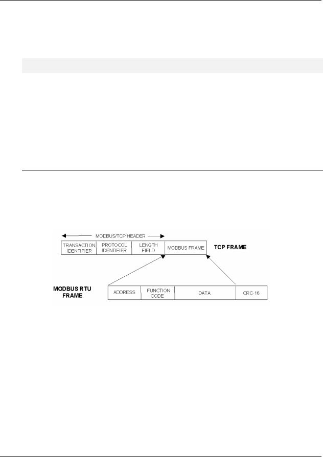
Introduction
Modbus/TCP Interface
The controller’s Ethernet 10/100Base-T Host port is used for the Modbus/TCP connection. Ethernet TCP allows multiple concurrent connections to hosts for data interchange. The HC900 (C30/C50) supports 5 concurrent host connections using Modbus/TCP protocol messaging via this port; HC900 (C70/C70R) supports 10.
Interface Preparation
ATTENTION
To access the controller you must have a current Hybrid Control Designer configuration file available. Some data is referenced relative to number, such as Signal Tags and Variables.
Other principal blocks, such as PID blocks, have offsets for parameter access dependent on the order in which the blocks were placed on the Function Block Diagram.
It is strongly recommended that you upload the controller configuration using the Hybrid Control Designer configuration tool to assure that you have a current configuration.
The Hybrid Control Designer tool provides a series of reports for use in Modbus Address identification. The «Tag Information» report lists the variables and Signal Tags in numeric order along with their Modbus Addresses.
A «Block Modbus Address» report lists the starting addresses for all principal blocks configured, identifying the offset.
Modbus/TCP Protocol
Modbus/TCP protocol, developed by Groupe Schneider’s Modicon Division, is a popular, open standard for data interchange over Ethernet TCP/IP networks using a Modbus RTU command structure.
It is simply an encapsulation of Modicon’s Modbus RTU protocol within a TCP/IP frame as shown below, which includes header information and the Modbus frame.
Figure 1-1 Modbus RTU Protocol within a TCP/IP Frame
The Open Modbus/TCP Specification is followed with respect to the physical, data link, and network layers. The message structure within the Modbus frame uses standard Modbus RTU function codes.
The Address part of the Modbus frame is not used (set to 00) since there is no sub-addressing intended or required. The controller IP address is the identifying address, set independently at the controller.
The error checking is supported by TCP/IP network protocols and not part of the Modbus frame.
The Transaction Identifiers and Protocol Identifiers in the header are normally all 0’s (4 bytes total) while the Length field identifies the number of bytes in the Modbus frame. The controller will transmit the correct number of bytes for the remainder of the frame. However, the controller does not check this field for messages received.
The standard IEEE 32-bit floating point and 16-bit integer formats are used.
|
2 |
HC900 Hybrid Controller Communications User Guide |
Revision 10 |
|
12/07 |
![]()
Introduction
Modbus/TCP Interface
Parameter Addressing
The definition in Table 6-1 is the fixed map overview listing starting and ending addresses.
Greater detail for parameter addressing relating to a particular function class (e.g, loops, setpoint programmer, signal tags) is in referenced sub-sections. Function Codes 1, 2, 3, 4, 5, 6, 8, 16 (10h), and 17 (11h) are supported (see Table 4-1 Modbus/TCP and Modbus RTU Function Codes Definitions).
Examples for read or write access to parameters supported by the various function codes are provided in Sections 4.3 through 4.11.
Reference
The Open Modbus/TCP Specification can be obtained at the Modicon website:
http://www.modicon.com/openmbus/standards/openmbus.htm
HC900 Ethernet Communications Setup
See the HC900 Hybrid Control (HC) Designer Users Guide, Doc. # 51-52-25-110 or respective HC Designer Help Files for setting up the following network parameters:
IP Address, Subnet Mask (optional), Default Gateway IP Address (optional)
1.Be sure the PC, HMI panel, or other Host device has a Network Interface Card (NIC) with an IP address (fixed or DHCP served) that allows access to controllers on the same or other subnet. Consult your IT department or network administrator for allocating IP addresses to the controllers as required.
2.You will need to set each controller’s IP address prior to network connection since every HC900 controller is shipped with the default IP address of 192.168.1.254. Placing multiple controllers on the same network before they have been given unique IP addresses will cause problems.
3.On the PC, use the Utilities Worksheet in the HC Designer software to set up the serial RS-232 connection to the controller at the desired baud rate. This will require a null modem cable.
4.Select the Set Controller’s Network Parameters button. Using the wizard (bottom radio button), select the PC COM port to be used, then set the controller’s new network parameters including IP address, Subnet Mask (if other than default, 255.255.255.0), and Default Gateway IP address (if required, otherwise leave at default 0.0.0.0). See your IT network administrator for proper entries. (Refer to the on-line help provided with the HC Designer software, Utilities Worksheet, Set Controller’s Network Parameters, for further details on this step).
Note: This setup will require the controller to be placed temporarily in the Program mode. After the new network parameters have been downloaded, the controller will conduct a Cold Start in its transition to RUN. This will cause an initialization if there is a current configuration in the controller.
The fixed IP address of each controller shall be set independently prior to placing on the network. See your IT systems administrator for allocating IP addresses, subnet masks, or default gateway IP address as necessary (network address filtering and routing may be necessary if the controller network access will not to be confined locally within the plant environment).
|
Revision 10 |
HC900 Hybrid Controller Communications User Guide |
3 |
|
12/07 |

Introduction
Modbus/TCP Interface
Ethernet 10/100Base-T Network Connections
Ethernet 10/100Base-T networks operating at 10/100MB/sec. are supported. A typical network arrangement is as shown below.
PC HMI
To other subnets
 Switch
10/100Base-T
10/100Base-T
RS232/RS485
Serial Ports S1 & S2
Ethernet Host Port E1
Ethernet Host Port E2
I/O Port
C70
Run/Pgm
Pgm Run
E1
E2
I/O
IP Address 193.142.165.45
IP Address 193.142.165.46
Figure 1-2 Ethernet 10/100Base-T Network Connections
Setting Up the Modbus/TCP Double Register Format
The HC900 predominantly uses an IEEE floating point format for communicating data to software applications providing Modbus/TCP protocol communications drivers. A floating point value is sent as (2) consecutive 16-bit registers, each register of which consists of two 8-bit bytes. Some software packages require the registers and bytes to be sent in a certain order. The controller can be configured to deliver the data in four different byte orders.
The Hybrid Control Designer software tool allows this order to be selected as follows:
1.Using the Utilities Worksheet in the HC Designer software, access the Set Controller Network Parameters button and make the selection to change the Modbus TCP Double Register Format (middle radio button).
2.With the Port selected for downloading this order (using a COM port or Network port), select the appropriate byte order format if the default (FP B) is not appropriate for the application. See Table 3-1, page 10.
3.Select Next and verify (by the response in the dialog box) that the change has been made in the controller. This order can be changed in the RUN mode.
The Modbus TCP double register transmission format selection, FP LB “Little Endian Byte-Swapped”, would be selected for interface to most third party software packages which use this format as standard. The default, FP B “Big Endian” is used with SpecView32 or Honeywell’s PlantScape/Experion/EBI software and follows the “Honeywell” default format of other control and recording products. It should be noted that most PC software packages offer a register (word) swap selection in their driver package anyway, so there should never be an incompatibility.
|
4 |
HC900 Hybrid Controller Communications User Guide |
Revision 10 |
|
12/07 |

Introduction
Modbus RTU RS232/RS485 Communication Ports
1.3 Modbus RTU RS232/RS485 Communication Ports
This implementation is designed to provide a popular data exchange format connecting the HC900 to both Honeywell and foreign master devices via the RS232 and RS485 communication ports. The Modbus RTU allows the instrument to be a citizen on a data link shared with other devices, which subscribe to the Modicon Modbus Protocol Reference Guide PI-MBUS-300 Rev. G specification.
These instruments DO NOT emulate any MODICON type device. The Modbus RTU specification is respected in the physical and data link layers. The message structure of the Modbus RTU function codes is employed and standard IEEE 32-bit floating point and integer formats are used. Data register mapping is unique to the HC900 and other Honeywell instruments. Section 6 describes the parameter mapping for the HC900.
Modbus RTU Message Format
|
Table 1-1 Modbus RTU Message Formats |
|
|
Coding system |
8 bit binary |
|
Number of data bits per |
10, 11, or 12 Bits |
|
character |
start bits — 1 |
|
data bits — 8 |
|
|
parity bits – 0 or 1 selectable |
|
|
stop bits – 1 or 2 selectable |
|
|
Parity |
None, odd, even selectable |
|
Bit transfer rate |
1200, 2400, 4800, 9600, 19200, 38400, 57600 Selectable |
|
Duplex |
Half duplex Transceiver or TX/RX |
|
Error checking |
CRC (cyclic redundancy check) |
|
Polynomial |
(CRC-16 10100000000001) |
|
Bit transfer order |
LSB first |
|
End of message |
Idle line for 3.5 or more characters (>1.82 msec for 19200). |
Modbus RTU Link Layer
The link layer includes the following properties/behaviors:
•Slave address recognition,
•Start / End of Frame detection,
•CRC-16 generation / checking,
•Transmit / receive message time-out,
•Buffer overflow detection,
•Framing error detection,
•Idle line detection.
Errors detected by the physical layer in messages received by the slave are ignored and the physical layer automatically restarts by initiating a new receive on the next idle line detection.
|
Revision 10 |
HC900 Hybrid Controller Communications User Guide |
5 |
|
12/07 |

Introduction
Modbus RTU RS232/RS485 Communication Ports
General Modbus RTU message format
Query message format
[Slave Address, Function Code, Function code dependent data, CRC 16]
Response message format
[Slave Address, Function Code*, Function code dependent data, CRC 16]
* If an error is detected in a valid message the response function code is modified by adding 80 (hex) and the function code dependent data is replaced by an exception response code as described in 5. Modbus RTU Exception Codes .
Between messages, the RS-485 link is in a high impedance state. During this time receiving devices are more susceptible to noise generated false start of messages. Although noise-generated messages are rejected due to address, framing, and CRC checking, they can cause the loss of a good message when they are included in the message stream. In the slave the transmitting device enables its transmitter line diver and forces an idle line state onto the link for three character time slots prior to transmitting. This forces termination of any noise generated messages and improves message frame synchronization.
Modbus RTU Data Layer
The data layer includes:
•Diagnostic loopback,
•Function code recognition / rejection,
•Busy / repoll,
•Data error code generation
Errors detected by the data layer are rejected and the slave responds to the polling device with a Modbustype status exception error. A summary of the Modbus status exception codes is listed in Section 5. Modbus RTU Exception Codes.
|
6 |
HC900 Hybrid Controller Communications User Guide |
Revision 10 |
|
12/07 |

IEEE 32-bit Floating Point Register Information
IEEE Floating Point Data Format
2. IEEE 32-bit Floating Point Register Information
The Modbus interface supports IEEE 32-bit floating point information for several of the function codes.
2.1 IEEE Floating Point Data Format
The formula for calculating the floating point number is:
mantissa x 2 (exponent -127)
(23 bit signed binary with 8 bit biased binary exponent)
|
byte 4 |
byte 3 |
byte 2 |
byte 1 |
||||
|
3 |
2 |
2 |
1 |
1 |
|||
|
1 |
4 |
3 |
6 |
5 |
8 |
7 |
0 |
|
xxxxxxxx |
x.xxxxxxx |
xxxxxxxx |
xxxxxxx |
mantissa (23 bits)
implied binary point for mantissa
exponent (8 bit unsigned value)
sign of the mantissa 0 = positive, 1 = negative
Figure 2-1 IEEE Floating Point Data format
Mantissa and Sign
The mantissa is defined by a sign bit (31) and a 23-bit binary fraction. This binary fraction is combined with an “implied” value of 1 to create a mantissa value, which is greater than or equal to 1.0 and less than 2.0.
The mantissa is positive if the sign bit is zero (reset), and negative if the sign bit is one (set). For example:
|
DECIMAL |
HEXADECIMAL |
BINARY |
|
100 |
42C80000 |
01000010 11001000 00000000 00000000 |
The sign bit (31) is zero, indicating a positive mantissa. Removing the sign bits and exponent bits, the mantissa becomes:
HEXADECIMAL BINARY
|
480000 |
xxxxxxxx x1001000 00000000 00000000 |
Add an “implied” value of one to the left of the binary point:
BINARY
1.1001000 00000000 00000000
Using positioned notation, this binary number is equal to:
10. +(1×2-1 ) +(0x2-2 ) +(0x2-3 ) +(1×2-4 ) =10. +05. +0.0 +0.0 +0.0625 =15625.
|
Revision 10 |
HC900 Hybrid Controller Communications User Guide |
7 |
|
12/07 |

Exponent
The exponent is defined by an unsigned 8-bit binary value (bits 23 through 30). The value of the exponent is derived by performing a signed subtraction of 127 (decimal) from the 8-bit exponent value.
|
DECIMAL |
HEXADECIMAL |
BINARY |
|
100 |
42C80000 |
01000010 11001000 00000000 00000000 |
Removing the sign and mantissa bits, the exponent becomes:
|
DECIMAL |
HEXADECIMAL |
BINARY |
|
133 |
85 |
x1000010 1xxxxxxx xxxxxxxx xxxxxxxx |
|
or: |
||
|
1×27 +0x26 |
+0x25 +0x24 |
+0x23 +1×22 +0x21 +1×20 |
Subtract a bias of 127 (decimal) from the exponent to determine its value: 133 – 127 = 6.
Mantissa and Exponent Combination
Combining the mantissa and exponent from the two previous examples:
float number = mantissa x 2exponent
float number = 1.5625 x 26 =15625. x 64 = 100.0
Below is a list of sample float values in IEEE format:
|
DECIMAL |
HEXADECIMAL |
|
100.0 |
42C80000 |
|
-100.0 |
C2C80000 |
|
0.5 |
3F000000 |
|
-1.75 |
BFE00000 |
|
0.0625 |
3D800000 |
|
1 |
3F800000 |
|
0 |
00000000 |
|
8 |
HC900 Hybrid Controller Communications User Guide |
Revision 10 |
|
12/07 |

IEEE 32-bit Floating Point Register Information
IEEE Floating Point Data Format
Reserved Operands
Per the Standard certain exceptional forms of floating point operands are excluded from the numbering system. These are as follows:
|
EXCEPTION |
EXPONENT |
MANTISSA |
|
+/- Infinity |
All 1’s |
All 0’s |
|
Not-a-Number (NAN) |
All 1’s |
Other than 0’s |
|
Denormalized Number |
All 0’s |
Other than 0’s |
|
Zero |
All 0’s |
All 0’s |
|
Revision 10 |
HC900 Hybrid Controller Communications User Guide |
9 |
|
12/07 |

3. Modbus Double Register Format
Data that is 32 bits requires 2 sequential registers (4 bytes) to transfer its data. Data of this type includes IEEE 32bit floating point, 32-bit signed integer and 32-bit unsigned integer. The stuffing order of the bytes into the two registers differs among Modbus/TCP hosts. To provide compatibility, the double register format for the HC900 controller is configurable.
To set the controller’s double register byte order, go to the “Set Controller Network Parameters ” wizard in the «Controller Utilities Function» section of the Utilities Tab on the Hybrid Control Designer and configure “Modbus Double Register Format”. This can be done in the RUN mode.
The selections are:
Table 3-1 Modbus Double Register Format Selections
|
Selection |
Description |
Byte order |
Notes |
|
(See Figure |
|||
|
2-1) |
|||
|
FP B |
Floating Point Big Endian Format |
4, 3, 2, 1 |
HC900 default |
|
FP BB |
Floating Point Big Endian with |
3, 4, 1, 2 |
|
|
byte-swapped |
|||
|
FP L |
Floating Point Little Endian Format |
1, 2, 3, 4 |
|
|
FP LB |
Floating Point Little Endian with |
2, 1, 4, 3 |
Modicon and |
|
byte-swapped |
Wonderware |
||
|
standard |
|||
See IEEE Formats on page IEEE Floating Point Formats on page 11 and 32-bit integer formats on page 13.
NOTE: Byte Swapping only applies to Function Codes 3, 4, and 16.
|
10 |
HC900 Hybrid Controller Communications User Guide |
Revision 10 |
|
12/07 |

Modbus Double Register Format
IEEE Floating Point Formats
3.1 IEEE Floating Point Formats
|
FP B — Floating Point Big Endian Format: |
||||
|
Bit 31 |
Bit 0 |
|||
|
E0 M22 M21M20 M19 M18 M17 M16 |
M7 M6 M5 M4 M3 M2 M1 M0 |
|||
|
S E7 E6 E5 E4 E3 E2 E1 |
M15 M14 M13 M12 M11 M10 M9 M8 |
|||
|
High |
Low |
High |
Low |
|
|
REGISTER N |
REGISTER N+1 |
|||
|
(High) |
(Low) |
|||
|
S=Sign |
E=Exponent |
M=Mantissa |
FP BB — Floating Point Big Endian with Byte Swapped Format:
|
Bit 31 |
Bit 24 |
Bit 15 |
Bit 8 |
||||||||||||||
|
S E7 E6 E5 E4 E3 E2 E1 |
M15 M14 M13 M12 M11 M10 M9 M8 |
||||||||||||||||
|
Bit 23 |
Bit 16 |
Bit 7 |
Bit 0 |
||||||||||||||
|
E0 M22 M21M20 M19 M18 M17 M16 |
M7 M6 M5 M4 M3 M2 M1 M0 |
|
High |
Low |
High |
Low |
|||
|
REGISTER N |
REGISTER N+1 |
|||||
|
(High) |
(Low) |
|||||
|
S=Sign E=Exponent |
M=Mantissa |
continued next page
|
Revision 10 |
HC900 Hybrid Controller Communications User Guide |
11 |
|
12/07 |
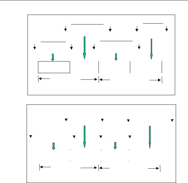
|
FP L — Floating Point Little Endian Format: |
||||
|
Bit 15 |
Bit 8 |
Bit 31 |
Bit 24 |
|
|
M15 M14 M13 M12 M11 M10 M9 M8 |
S E7 E6 E5 E4 E3 E2 E1 |
|||
|
Bit 7 |
Bit 0 |
Bit 23 |
Bit 16 |
|
|
M7 M6 M5 M4 M3 M2 M1 M0 |
E0 M22 M21M20 M19 M18 M17 M16 |
|||
|
High |
Low |
High |
Low |
|
|
REGISTER N |
REGISTER N+1 |
|||
|
(High) |
(Low) |
|||
|
S=Sign |
E=Exponent M=Mantissa |
FP LB — Floating Point Little Endian with Byte Swapped Format:
|
Bit 7 |
Bit 0 |
Bit 23 |
Bit 16 |
|||||||||||||
|
M7 M6 M5 M4 M3 M2 M1 M0 |
E0 M22 M21M20 M19 M18 M17 M16 |
|||||||||||||||
|
Bit 15 |
Bit 8 |
Bit 31 |
Bit 24 |
|||||||||||||
|
M15 M14 M13 M12 M11 M10 M9 M8 |
S E7 E6 E5 E4 E3 E2 E1 |
|
High |
Low |
High |
Low |
||
|
REGISTER N |
REGISTER N+1 |
||||
|
(High) |
(Low) |
S=Sign E=Exponent M=Mantissa
Figure 3-1 IEEE Floating Point Formats
Table 3-2 IEEE Floating Point Number Examples in FP B Format
|
Value |
IEEE FP B |
Register N |
Register N+1 |
||||||||
|
(decimal) |
MSB LSB |
high |
low |
high |
low |
||||||
|
100.0 |
42C80000h |
42h |
C8h |
00h |
00h |
||||||
|
55.32 |
425D47AEh |
42h |
5Dh |
47h |
AEh |
||||||
|
2.0 |
40000000h |
40h |
00h |
00h |
00h |
||||||
|
1.0 |
3F800000h |
3Fh |
80h |
00h |
00h |
||||||
|
-1.0 |
BF800000h |
BFh |
80h |
00h |
00h |
||||||
|
12 |
HC900 Hybrid Controller Communications User Guide |
Revision 10 |
|||||||||
|
12/07 |
![]()
Modbus Double Register Format
Unsigned/signed 32-bit Register Formats
3.2 Unsigned/signed 32-bit Register Formats
The formats descriptions below use the value 12345678 Hex as an example. Where the binary representation is:
|
Byte 4 = 12 Hex |
Byte 3 = 34 Hex |
Byte 2 = 56 Hex |
Byte 1 = 78 Hex |
|||||||||||||||||||||||||||||||
|
Bits |
31 |
30 |
29 |
28 |
27 |
26 |
25 |
24 |
23 |
22 |
21 |
20 |
19 |
18 |
17 |
16 |
15 |
14 |
13 |
12 |
11 |
10 |
9 |
8 |
7 |
6 |
5 |
4 |
3 |
2 |
1 |
0 |
||
|
0 |
0 |
0 |
1 |
0 |
0 |
1 |
0 |
0 |
0 |
1 |
1 |
0 |
1 |
0 |
0 |
0 |
1 |
0 |
1 |
0 |
1 |
1 |
0 |
0 |
1 |
1 |
1 |
1 |
0 |
0 |
0 |
|||
FP B – Big Endian Format
The value 12345678 Hex will be represented as follows:
|
Bit 31 |
Bit 0 |
||||
|
Byte 4 |
Byte 3 |
Byte 2 |
Byte 1 |
||
|
12 Hex |
34 Hex |
56 Hex |
78 Hex |
|
REGISTER N |
REGISTER N+1 |
||||
|
(High) |
(Low) |
||||
|
Revision 10 |
HC900 Hybrid Controller Communications User Guide |
13 |
|
12/07 |
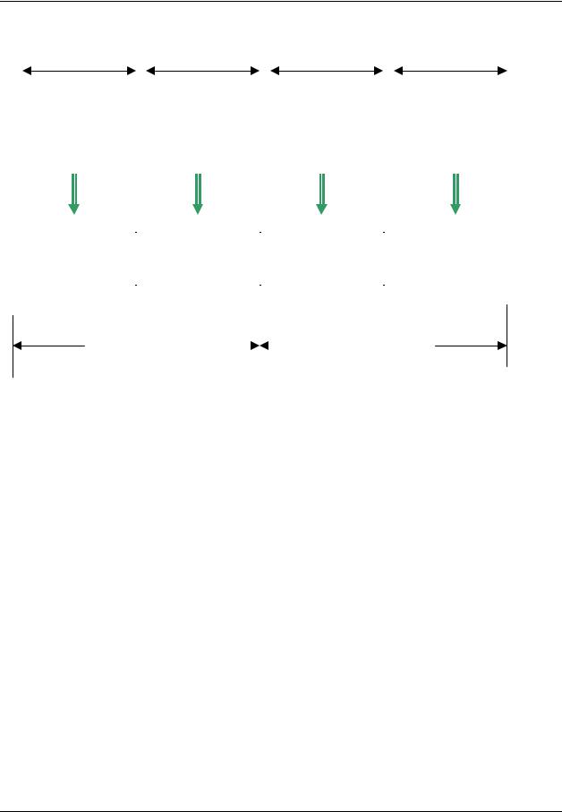
FP BB – Big Endian Byte Swapped Format
The value 12345678 Hex will be represented as follows:
Bit 23 Bit 16 Bit 31 Bit 24 Bit 7 Bit 0 Bit 15 Bit 8
|
Byte 3 |
Byte 4 |
Byte 1 |
Byte 2 |
|
34 Hex |
12 Hex |
78 Hex |
56 Hex |
|
REGISTER N |
REGISTER N+1 |
||||
|
(High) |
(Low) |
||||
|
14 |
HC900 Hybrid Controller Communications User Guide |
Revision 10 |
|
12/07 |

Modbus Double Register Format
Unsigned/signed 32-bit Register Formats
FP L – Little Endian Format
The value 12345678 Hex will be represented as follows:
|
Bit 7 |
Bit 0 Bit 15 |
Bit 8 Bit 23 |
Bit 16 |
Bit 31 |
Bit 24 |
|
Byte 1 |
Byte 2 |
Byte 3 |
Byte 4 |
||
|
78 Hex |
56 Hex |
34 Hex |
12 Hex |
|
REGISTER N |
REGISTER N+1 |
||||
|
(High) |
(Low) |
||||
|
Revision 10 |
HC900 Hybrid Controller Communications User Guide |
15 |
|
12/07 |
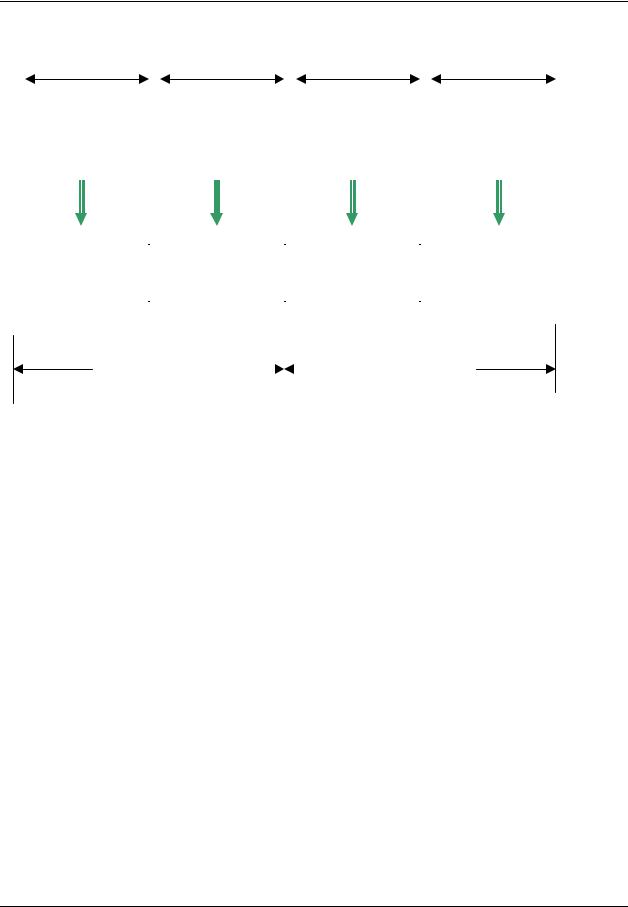
FP LB – Little Endian Byte Swap Format
The value 12345678 Hex will be represented as follows:
|
Bit 15 |
Bit 8 Bit 7 |
Bit 0 Bit 31 |
Bit 24 |
Bit 23 |
Bit 16 |
|
Byte 2 |
Byte 1 |
Byte 4 |
Byte 3 |
||
|
56 Hex |
78 Hex |
12 Hex |
34 Hex |
|
REGISTER N |
REGISTER N+1 |
||||
|
(High) |
(Low) |
||||
|
16 |
HC900 Hybrid Controller Communications User Guide |
Revision 10 |
|
12/07 |

Modbus/TCP & Modbus RTU Function Codes
Function code definitions
4.Modbus/TCP & Modbus RTU Function Codes
4.1Function code definitions
The HC900 Modbus protocol uses a subset of the standard Modbus function codes to provide access to processrelated information. These standard function codes provide basic support for IEEE 32-bit floating point numbers, 32-bit unsigned/signed integer and 16-bit integer register representation of instrument’s process data.
Repolling of data is not supported by this instrument.
Table 4-1 Modbus/TCP and Modbus RTU Function Codes Definitions
|
Function Code |
Name |
Usage |
|
01 |
Read Coil Status |
Read the state of a digital output |
|
02 |
Read Input Status |
Read the state of a digital input |
|
03 |
Read Holding Registers |
Read data in 16-bit Register Format (high/low). Used to read |
|
integer or floating point process data. Registers are |
||
|
consecutive and are imaged from the instrument to the host. |
||
|
04 |
Read Input Registers |
Provides Read access to any Analog Input Channel |
|
positioned in any Rack or Slot. |
||
|
05 |
Force Single Coil |
Write data to force a digital output ON/OFF |
|
Values of FF 00 forces digital output ON |
||
|
Values of 00 00 forces digital output OFF |
||
|
Values of FF FF releases the force of the digital output |
||
|
All other values are illegal and will not effect the digital output. |
||
|
06 |
Preset Single Register |
Write Data in 16-bit Integer Format (high/low) ONLY. |
|
08 |
Loopback Test |
Used for diagnostic testing of the communications port. |
|
16 (10h) |
Preset Multiple Registers |
Write Data in 16-bit Format (high/low). Used to write integer |
|
and floating point override data. Registers are consecutive |
||
|
and are imaged from the host to the instrument. |
||
|
17 (11h) |
Report Device ID |
Read instrument ID and connection information, ROM version, |
|
etc. |
||
|
Revision 10 |
HC900 Hybrid Controller Communications User Guide |
17 |
|
12/07 |

4.2 Fixed Modbus Map
Table 4-2 and Table 4-3 list the the maximum number of Object Addresses and maximum number of registers allowed per request. Also shown are differences between firmware versions 2.3 and 2.4.
Note 1: In versions 4.0 and higher these maximums apply to fixed map but not to the custom map. Note 2: In versions 4.0 and higher function code 03 is not available for analog inputs.
Table 4-2 Maximum Number of Objects (fixed map only)
Note: objects marked with * have multiple parameters and therefore occupy multiple registers. For example, a PID loop has over 40 parameters that can be accessed.
|
Object Name |
Max. No. of Objects |
Function Code |
|||||
|
C30 |
C50/C70/C70R |
||||||
|
Analog Inputs |
96/12 slots v2.3 |
640 v2.3 |
3: can only access first 8 |
||||
|
192/12 slots v2.4 |
1280 v2.4 |
slots of rack 1. Not available |
|||||
|
in version 4.0 or higher. |
|||||||
|
4: can access all slots and |
|||||||
|
racks |
|||||||
|
Discrete Input |
192/12 slots v2.3 |
1280 v2.3 |
2 |
||||
|
384/12 slots v2.4 |
2560 v2.4 |
||||||
|
Discrete Output/Coil |
192/12 slots v2.3 |
1280 v2.3 |
1: read |
||||
|
384/12 slots v2.4 |
2560 v2.4 |
5: force |
|||||
|
Loop* |
8 |
32 |
3 |
||||
|
Variable Value |
600 |
600 |
3 |
||||
|
Set Point Programmer Value* |
8 |
8 |
3 |
||||
|
Segments per Set Point |
50 |
50 |
3 |
||||
|
Programmer* |
|||||||
|
Signal tags |
2000 |
2000 (C50) |
3 |
||||
|
5000 (C70/C70R) |
|||||||
|
Scheduler Value* |
2 |
2 |
3 |
||||
|
Segments per Schedule* |
50 |
50 |
3 |
||||
|
Sequencer* |
4 |
4 |
3 |
||||
|
Stage* |
8 |
8 |
3 |
||||
|
Ramp* |
8 |
8 |
3 |
||||
|
Hand-Off-Auto* |
16 |
16 |
3 |
||||
|
Alternator* |
6 |
6 |
3 |
||||
|
Device Control* |
16 |
16 |
3 |
||||
|
User Defined Registers |
1024 |
1024 |
3 |
|
18 |
HC900 Hybrid Controller Communications User Guide |
Revision 10 |
|
12/07 |

Modbus/TCP & Modbus RTU Function Codes
Fixed Modbus Map
Table 4-3 Maximum Number of Registers Allowable per Request
|
Function |
Max. No. of |
|
|
Code |
Registers |
|
|
1, 2 |
2040 bits |
|
|
3, 4 |
127 Registers |
|
|
63 Floats |
||
|
5 |
1 |
Coil |
|
6 |
1 |
Register |
|
10h |
127 Registers |
|
|
63 Floats |
||
|
Revision 10 |
HC900 Hybrid Controller Communications User Guide |
19 |
|
12/07 |

4.3 Function Code 01 – Read Digital Output Status
Description
Function code 01 (0X references) is used to read a digital output’s ON/OFF status of the HC900 using 16 bit addressing for DO access and data is returned in a binary format mapped into bytes.
The Modbus Comm Digital I/O Channel-to-address mapping is shown starting on page 26. Broadcast is not supported.
Query
The query message specifies the starting Digital Output (DO) and the quantity of DOs to read. The DO address in the message is based on the rack slot and channel number of the digital output being read.
Example Query: Read DO channels 1 to 16, located in Rack #1, Slot #1; from the controller with slave address 1.
Query message format for function code 01
|
Slave |
Function |
Starting |
Starting |
Number |
Number |
CRC |
CRC |
||
|
Address |
Code |
Address |
Address |
DO |
DO |
(RTU) |
(RTU) |
||
|
(00 for TCP) |
High |
Low |
High |
Low |
|||||
|
TCP Example |
00 |
01 |
00 |
00 |
00 |
10 |
|||
|
RTU Example |
01 |
01 |
00 |
00 |
00 |
10 |
CRC |
CRC |
|
Response
The DO status in the response message is packed as one DO per bit of the data field. Status is indicated as: 1 = ON; 0 = OFF. The LSB of the first data byte contains the DO addressed in the query. The other DOs follow toward the high order end of this byte, and from low order to high order in subsequent bytes.
If the returned DO quantity is not a multiple of eight, the remaining bits in the final data byte will be padded with zeros (toward the high order end of the byte). The byte count field specifies the quantity of data bytes returned.
Example Response: DO channels 2 and 6 located in Rack #1, Slot #1 are on; all others are off.
Response message format for function code 01
|
Slave |
Function |
Byte |
Data |
Data |
CRC |
CRC |
|
|
Address |
Code |
Count |
(RTU) |
(RTU) |
|||
|
(00 for TCP) |
|||||||
|
TCP Example |
00 |
01 |
02 |
22 |
00 |
||
|
RTU Example |
01 |
01 |
02 |
22 |
00 |
CRC |
CRC |
In the response the status of DOs 1 — 8 is shown as the byte value 22 hex, or 0010 0010 binary. DO 8 is the MSB of this byte, and DO 1 is the LSB. Left to right, the status of DO 8 through 1 is: OFF-OFF-ON-OFF- OFF-OFF-ON-OFF. The status of DOs 9 — 16 are shown a 00hex, or 0000 0000 with the same bit ordering.
|
20 |
HC900 Hybrid Controller Communications User Guide |
Revision 10 |
|
12/07 |

Modbus/TCP & Modbus RTU Function Codes
Function Code 01 – Read Digital Output Status
Digital I/O Channel to Address Mapping
If you have any 32-channel DI/DO modules or if you have firmware version 2.4 or higher you must use the newer maps in Table 4-4 and Table 4-5. However, use the older maps in Table 4-6 and Table 4-7 if:
•Your controller is firmware version 2.3 or earlier or
•You have already mapped out 16-channel DI/DO, have no 32-channel DI/DO modules, and don’t want to change to the newer map.
Note: Up to 16 slots are accommodated in the protocol even though the largest rack available supports 12 slots.
Each DI/DO consumes 1 Modbus bit address.
Decimal addressing is typically non-zero based for DI/DO access (1-based), applicable to coil or register address.
Table 4-4 DI/DO Address Map (v2.4 and higher, up to 32-channel)
|
Rack |
Channels |
Coil number/register number |
Modbus Hex |
|||
|
Address Range |
||||||
|
1* |
1 — 512 |
2001 |
– 2512 |
7D0 |
– 9CF |
|
|
2 |
513 – 1024 |
2513 |
– 3024 |
9D0 |
– BCF |
|
|
3 |
1025 |
– 1536 |
3025 |
– 3536 |
BD0 – DCF |
|
|
4 |
1537 |
— 2048 |
3537 |
– 4048 |
DD0 – FCF |
|
|
5 |
2049 |
— 2560 |
4049 |
— 4560 |
FD0 – 11CF |
|
|
*See Table 4-5 for detailed map of Rack |
#1 |
|||||
The coil (register) number for a DI/DO is based on the DI/DO’s position in the card cage. It is determined from the formula:
Coil (register) Number = [(Rack-1)*512] + [(Slot-1)*32] + channel in module + 2000
Example: To monitor a coil (register) located in the 2nd channel of slot 10 of rack 3, the Modbus coil (register) number is:
[(3-1)*512] + [(10-1)*32] + 2 + 2000 = 3314
Some third party software packages will require the 1-based coil/register number to be used for the address while others will require the 0-based hex address.
|
Revision 10 |
HC900 Hybrid Controller Communications User Guide |
21 |
|
12/07 |

Table 4-5 Rack #1 DI/DO Address map (version 2.4 and higher, up to 32-channel)
|
Slot 1 |
Slot 2 |
Slot 3 |
Slot 4 |
|||||||||||
|
CH# |
Coil/ |
Addr. |
CH# |
Coil/ |
Addr. |
CH# |
Coil/ |
Addr. |
CH# |
Coil/ |
Addr. |
|||
|
register |
Hex |
register |
Hex |
register |
Hex |
register |
Hex |
|||||||
|
32 |
2032 |
7EF |
32 |
2064 |
80F |
32 |
2096 |
82F |
32 |
2128 |
84F |
|||
|
31 |
2031 |
7EE |
31 |
2063 |
80E |
31 |
2095 |
82E |
31 |
2127 |
84E |
|||
|
30 |
2030 |
7ED |
30 |
2062 |
80D |
30 |
2094 |
82D |
30 |
2126 |
84D |
|||
|
29 |
2029 |
7EC |
29 |
2061 |
80C |
29 |
2093 |
82C |
29 |
2125 |
84C |
|||
|
28 |
2028 |
7EB |
28 |
2060 |
80B |
28 |
2092 |
82B |
28 |
2124 |
84B |
|||
|
27 |
2027 |
7EA |
27 |
2059 |
80A |
27 |
2091 |
82A |
27 |
2123 |
84A |
|||
|
26 |
2026 |
7E9 |
26 |
2058 |
809 |
26 |
2090 |
829 |
26 |
2122 |
849 |
|||
|
25 |
2025 |
7E8 |
25 |
2057 |
808 |
25 |
2089 |
828 |
25 |
2121 |
848 |
|||
|
24 |
2024 |
7E7 |
24 |
2056 |
807 |
24 |
2088 |
827 |
24 |
2120 |
847 |
|||
|
23 |
2023 |
7E6 |
23 |
2055 |
806 |
23 |
2087 |
826 |
23 |
2119 |
846 |
|||
|
22 |
2022 |
7E5 |
22 |
2054 |
805 |
22 |
2086 |
825 |
22 |
2118 |
845 |
|||
|
21 |
2021 |
7E4 |
21 |
2053 |
804 |
21 |
2085 |
824 |
21 |
2117 |
844 |
|||
|
20 |
2020 |
7E3 |
20 |
2052 |
803 |
20 |
2084 |
823 |
20 |
2116 |
843 |
|||
|
19 |
2019 |
7E2 |
19 |
2051 |
802 |
19 |
2083 |
822 |
19 |
2115 |
842 |
|||
|
18 |
2018 |
7E1 |
18 |
2050 |
801 |
18 |
2082 |
821 |
18 |
2114 |
841 |
|||
|
17 |
2017 |
7E0 |
17 |
2049 |
800 |
17 |
2081 |
820 |
17 |
2113 |
840 |
|||
|
16 |
2016 |
7DF |
16 |
2048 |
7FF |
16 |
2080 |
81F |
16 |
2112 |
83F |
|||
|
15 |
2015 |
7DE |
15 |
2047 |
7FE |
15 |
2079 |
81E |
15 |
2111 |
83E |
|||
|
14 |
2014 |
7DD |
14 |
2046 |
7FD |
14 |
2078 |
81D |
14 |
2110 |
83D |
|||
|
13 |
2013 |
7DC |
13 |
2045 |
7FC |
13 |
2077 |
81C |
13 |
2109 |
83C |
|||
|
12 |
2012 |
7DB |
12 |
2044 |
7FB |
12 |
2076 |
81B |
12 |
2108 |
83B |
|||
|
11 |
2011 |
7DA |
11 |
2043 |
7FA |
11 |
2075 |
81A |
11 |
2107 |
83A |
|||
|
10 |
2010 |
7D9 |
10 |
2042 |
7F9 |
10 |
2074 |
819 |
10 |
2106 |
839 |
|||
|
9 |
2009 |
7D8 |
9 |
2041 |
7F8 |
9 |
2073 |
818 |
9 |
2105 |
838 |
|||
|
8 |
2008 |
7D7 |
8 |
2040 |
7F7 |
8 |
2072 |
817 |
8 |
2104 |
837 |
|||
|
7 |
2007 |
7D6 |
7 |
2039 |
7F6 |
7 |
2071 |
816 |
7 |
2103 |
836 |
|||
|
6 |
2006 |
7D5 |
6 |
2038 |
7F5 |
6 |
2070 |
815 |
6 |
2102 |
835 |
|||
|
5 |
2005 |
7D4 |
5 |
2037 |
7F4 |
5 |
2069 |
814 |
5 |
2101 |
834 |
|||
|
4 |
2004 |
7D3 |
4 |
2036 |
7F3 |
4 |
2068 |
813 |
4 |
2100 |
833 |
|||
|
3 |
2003 |
7D2 |
3 |
2035 |
7F2 |
3 |
2067 |
812 |
3 |
2099 |
832 |
|||
|
2 |
2002 |
7D1 |
2 |
2034 |
7F1 |
2 |
2066 |
811 |
2 |
2098 |
831 |
|||
|
1 |
2001 |
7D0 |
1 |
2033 |
7F0 |
1 |
2065 |
810 |
1 |
2097 |
830 |
|
22 |
HC900 Hybrid Controller Communications User Guide |
Revision 10 |
|
12/07 |
![]()
Modbus/TCP & Modbus RTU Function Codes
Function Code 01 – Read Digital Output Status
|
Slot 5 |
Slot 6 |
Slot 7 |
Slot 8 |
|||||||||||
|
CH# |
Coil/ |
Addr. |
CH# |
Coil/ |
Addr. |
CH# |
Coil/ |
Addr. |
CH# |
Coil/ |
Addr. |
|||
|
register |
Hex |
register |
Hex |
register |
Hex |
register |
Hex |
|||||||
|
32 |
2160 |
86F |
32 |
2192 |
88F |
32 |
2224 |
8AF |
32 |
2256 |
8D0 |
|||
|
31 |
2159 |
86E |
31 |
2191 |
88E |
31 |
2223 |
8AE |
31 |
2255 |
8CE |
|||
|
30 |
2158 |
86D |
30 |
2190 |
88D |
30 |
2222 |
8AD |
30 |
2254 |
8CD |
|||
|
29 |
2157 |
86C |
29 |
2189 |
88C |
29 |
2221 |
8AC |
29 |
2253 |
8CC |
|||
|
28 |
2156 |
86B |
28 |
2188 |
88B |
28 |
2220 |
8AB |
28 |
2252 |
8CB |
|||
|
27 |
2155 |
86A |
27 |
2187 |
88A |
27 |
2219 |
8AA |
27 |
2251 |
8CA |
|||
|
26 |
2154 |
869 |
26 |
2186 |
889 |
26 |
2218 |
8A9 |
26 |
2250 |
8C9 |
|||
|
25 |
2153 |
868 |
25 |
2185 |
888 |
25 |
2217 |
8A8 |
25 |
2249 |
8C8 |
|||
|
24 |
2152 |
867 |
24 |
2184 |
887 |
24 |
2216 |
8A7 |
24 |
2248 |
8C7 |
|||
|
23 |
2151 |
866 |
23 |
2183 |
886 |
23 |
2215 |
8A6 |
23 |
2247 |
8C6 |
|||
|
22 |
2150 |
865 |
22 |
2182 |
885 |
22 |
2214 |
8A5 |
22 |
2246 |
8C5 |
|||
|
21 |
2149 |
864 |
21 |
2181 |
884 |
21 |
2213 |
8A4 |
21 |
2245 |
8C4 |
|||
|
20 |
2148 |
863 |
20 |
2180 |
883 |
20 |
2212 |
8A3 |
20 |
2244 |
8C3 |
|||
|
19 |
2147 |
862 |
19 |
2179 |
882 |
19 |
2211 |
8A2 |
19 |
2243 |
8C2 |
|||
|
18 |
2146 |
861 |
18 |
2178 |
881 |
18 |
2210 |
8A1 |
18 |
2242 |
8C1 |
|||
|
17 |
2145 |
860 |
17 |
2177 |
880 |
17 |
2209 |
8A0 |
17 |
2241 |
8C0 |
|||
|
16 |
2144 |
85F |
16 |
2176 |
87F |
16 |
2208 |
89F |
16 |
2240 |
8BF |
|||
|
15 |
2143 |
85E |
15 |
2175 |
87E |
15 |
2207 |
89E |
15 |
2239 |
8BE |
|||
|
14 |
2142 |
85D |
14 |
2174 |
87D |
14 |
2206 |
89D |
14 |
2238 |
8BD |
|||
|
13 |
2141 |
85C |
13 |
2173 |
87C |
13 |
2205 |
89C |
13 |
2237 |
8BC |
|||
|
12 |
2140 |
85B |
12 |
2172 |
87B |
12 |
2204 |
89B |
12 |
2236 |
8BB |
|||
|
11 |
2139 |
85A |
11 |
2171 |
87A |
11 |
2203 |
89A |
11 |
2235 |
8BA |
|||
|
10 |
2138 |
859 |
10 |
2170 |
879 |
10 |
2202 |
899 |
10 |
2234 |
8B9 |
|||
|
9 |
2137 |
858 |
9 |
2169 |
878 |
9 |
2201 |
898 |
9 |
2233 |
8B8 |
|||
|
8 |
2136 |
857 |
8 |
2168 |
877 |
8 |
2200 |
897 |
8 |
2232 |
8B7 |
|||
|
7 |
2135 |
856 |
7 |
2167 |
876 |
7 |
2199 |
896 |
7 |
2231 |
8B6 |
|||
|
6 |
2134 |
855 |
6 |
2166 |
875 |
6 |
2198 |
895 |
6 |
2230 |
8B5 |
|||
|
5 |
2133 |
854 |
5 |
2165 |
874 |
5 |
2197 |
894 |
5 |
2229 |
8B4 |
|||
|
4 |
2132 |
853 |
4 |
2164 |
873 |
4 |
2196 |
893 |
4 |
2228 |
8B3 |
|||
|
3 |
2131 |
852 |
3 |
2163 |
872 |
3 |
2195 |
892 |
3 |
2227 |
8B2 |
|||
|
2 |
2130 |
851 |
2 |
2162 |
871 |
2 |
2194 |
891 |
2 |
2226 |
8B1 |
|||
|
1 |
2129 |
850 |
1 |
2161 |
870 |
1 |
2193 |
890 |
1 |
2225 |
8B0 |
|
Revision 10 |
HC900 Hybrid Controller Communications User Guide |
23 |
|
12/07 |

|
Slot 9 |
Slot 10 |
Slot 11 |
Slot 12 |
|||||||||||
|
CH# |
Coil/ |
Addr. |
CH# |
Coil/ |
Addr. |
CH# |
Coil/ |
Addr. |
CH# |
Coil/ |
Addr. |
|||
|
register |
Hex |
register |
Hex |
register |
Hex |
register |
Hex |
|||||||
|
32 |
2288 |
8EF |
32 |
2320 |
90F |
32 |
2352 |
92F |
32 |
2384 |
94F |
|||
|
31 |
2287 |
8EE |
31 |
2319 |
90E |
31 |
2351 |
92E |
31 |
2383 |
94E |
|||
|
30 |
2286 |
8ED |
30 |
2318 |
90D |
30 |
2350 |
92D |
30 |
2382 |
94D |
|||
|
29 |
2285 |
8EC |
29 |
2317 |
90C |
29 |
2349 |
92C |
29 |
2381 |
94C |
|||
|
28 |
2284 |
8EB |
28 |
2316 |
90B |
28 |
2348 |
92B |
28 |
2380 |
94B |
|||
|
27 |
2283 |
8EA |
27 |
2315 |
90A |
27 |
2347 |
92A |
27 |
2379 |
94A |
|||
|
26 |
2282 |
8E9 |
26 |
2314 |
909 |
26 |
2346 |
929 |
26 |
2378 |
949 |
|||
|
25 |
2281 |
8E8 |
25 |
2313 |
908 |
25 |
2345 |
928 |
25 |
2377 |
948 |
|||
|
24 |
2280 |
8E7 |
24 |
2312 |
907 |
24 |
2344 |
927 |
24 |
2376 |
947 |
|||
|
23 |
2279 |
8E6 |
23 |
2311 |
906 |
23 |
2343 |
926 |
23 |
2375 |
946 |
|||
|
22 |
2278 |
8E5 |
22 |
2310 |
905 |
22 |
2342 |
925 |
22 |
2374 |
945 |
|||
|
21 |
2277 |
8E4 |
21 |
2309 |
904 |
21 |
2341 |
924 |
21 |
2373 |
944 |
|||
|
20 |
2276 |
8E3 |
20 |
2308 |
903 |
20 |
2340 |
923 |
20 |
2372 |
943 |
|||
|
19 |
2275 |
8E2 |
19 |
2307 |
902 |
19 |
2339 |
922 |
19 |
2371 |
942 |
|||
|
18 |
2274 |
8E1 |
18 |
2306 |
901 |
18 |
2338 |
921 |
18 |
2370 |
941 |
|||
|
17 |
2273 |
8E0 |
17 |
2305 |
900 |
17 |
2337 |
920 |
17 |
2369 |
940 |
|||
|
16 |
2272 |
8DF |
16 |
2304 |
8FF |
16 |
2336 |
91F |
16 |
2368 |
93F |
|||
|
15 |
2271 |
8DE |
15 |
2303 |
8FE |
15 |
2335 |
91E |
15 |
2367 |
93E |
|||
|
14 |
2270 |
8DD |
14 |
2302 |
8FD |
14 |
2334 |
91D |
14 |
2366 |
93D |
|||
|
13 |
2269 |
8DC |
13 |
2301 |
8FC |
13 |
2333 |
91C |
13 |
2365 |
93C |
|||
|
12 |
2268 |
8DB |
12 |
2300 |
8FB |
12 |
2332 |
91B |
12 |
2364 |
93B |
|||
|
11 |
2267 |
8DA |
11 |
2299 |
8FA |
11 |
2331 |
91A |
11 |
2363 |
93A |
|||
|
10 |
2266 |
8D9 |
10 |
2298 |
8F9 |
10 |
2330 |
919 |
10 |
2362 |
939 |
|||
|
9 |
2265 |
8D8 |
9 |
2297 |
8F8 |
9 |
2329 |
918 |
9 |
2361 |
938 |
|||
|
8 |
2264 |
8D7 |
8 |
2296 |
8F7 |
8 |
2328 |
917 |
8 |
2360 |
937 |
|||
|
7 |
2263 |
8D6 |
7 |
2295 |
8F6 |
7 |
2327 |
916 |
7 |
2359 |
936 |
|||
|
6 |
2262 |
8D5 |
6 |
2294 |
8F5 |
6 |
2326 |
915 |
6 |
2358 |
935 |
|||
|
5 |
2261 |
8D4 |
5 |
2293 |
8F4 |
5 |
2325 |
914 |
5 |
2357 |
934 |
|||
|
4 |
2260 |
8D3 |
4 |
2292 |
8F3 |
4 |
2324 |
913 |
4 |
2356 |
933 |
|||
|
3 |
2259 |
8D2 |
3 |
2291 |
8F2 |
3 |
2323 |
912 |
3 |
2355 |
932 |
|||
|
2 |
2258 |
8D1 |
2 |
2290 |
8F1 |
2 |
2322 |
911 |
2 |
2354 |
931 |
|||
|
1 |
2257 |
8D0 |
1 |
2289 |
8F0 |
1 |
2321 |
910 |
1 |
2353 |
930 |
|||
|
24 |
HC900 Hybrid Controller Communications User Guide |
Revision 10 |
|
12/07 |

Modbus/TCP & Modbus RTU Function Codes
Function Code 01 – Read Digital Output Status
|
Slot 13 |
Slot 14 |
Slot 15 |
Slot 16 |
|||||||||||
|
CH# |
Coil/ |
Addr. |
CH# |
Coil/ |
Addr. |
CH# |
Coil/ |
Addr. |
CH# |
Coil/ |
Addr. |
|||
|
register |
Hex |
register |
Hex |
register |
Hex |
register |
Hex |
|||||||
|
32 |
2416 |
96F |
32 |
2448 |
98F |
32 |
2480 |
9AF |
32 |
2512 |
9CF |
|||
|
31 |
2415 |
96E |
31 |
2447 |
98E |
31 |
2479 |
9AE |
31 |
2511 |
9CE |
|||
|
30 |
2414 |
96D |
30 |
2446 |
98D |
30 |
2478 |
9AD |
30 |
2510 |
9CD |
|||
|
29 |
2413 |
96C |
29 |
2445 |
98C |
29 |
2477 |
9AC |
29 |
2509 |
9CC |
|||
|
28 |
2412 |
96B |
28 |
2444 |
98B |
28 |
2476 |
9AB |
28 |
2508 |
9CB |
|||
|
27 |
2411 |
96A |
27 |
2443 |
98A |
27 |
2475 |
9AA |
27 |
2507 |
9CA |
|||
|
26 |
2410 |
969 |
26 |
2442 |
989 |
26 |
2474 |
9A9 |
26 |
2506 |
9C9 |
|||
|
25 |
2409 |
968 |
25 |
2441 |
988 |
25 |
2473 |
9A8 |
25 |
2505 |
9C8 |
|||
|
24 |
2408 |
967 |
24 |
2440 |
987 |
24 |
2472 |
9A7 |
24 |
2504 |
9C7 |
|||
|
23 |
2407 |
966 |
23 |
2439 |
986 |
23 |
2471 |
9A6 |
23 |
2503 |
9C6 |
|||
|
22 |
2406 |
965 |
22 |
2438 |
985 |
22 |
2470 |
9A5 |
22 |
2502 |
9C5 |
|||
|
21 |
2405 |
964 |
21 |
2437 |
984 |
21 |
2469 |
9A4 |
21 |
2501 |
9C4 |
|||
|
20 |
2404 |
963 |
20 |
2436 |
983 |
20 |
2468 |
9A3 |
20 |
2500 |
9C3 |
|||
|
19 |
2403 |
962 |
19 |
2435 |
982 |
19 |
2467 |
9A2 |
19 |
2499 |
9C2 |
|||
|
18 |
2402 |
961 |
18 |
2434 |
981 |
18 |
2466 |
9A1 |
18 |
2498 |
9C1 |
|||
|
17 |
2401 |
960 |
17 |
2433 |
980 |
17 |
2465 |
9A0 |
17 |
2497 |
9C0 |
|||
|
16 |
2400 |
95F |
16 |
2432 |
97F |
16 |
2464 |
99F |
16 |
2496 |
9BF |
|||
|
15 |
2399 |
95E |
15 |
2431 |
97E |
15 |
2463 |
99E |
15 |
2495 |
9BE |
|||
|
14 |
2398 |
95D |
14 |
2430 |
97D |
14 |
2462 |
99D |
14 |
2494 |
9BD |
|||
|
13 |
2397 |
95C |
13 |
2429 |
97C |
13 |
2461 |
99C |
13 |
2493 |
9BC |
|||
|
12 |
2396 |
95B |
12 |
2428 |
97B |
12 |
2460 |
99B |
12 |
2492 |
9BB |
|||
|
11 |
2395 |
95A |
11 |
2427 |
97A |
11 |
2459 |
99A |
11 |
2491 |
9BA |
|||
|
10 |
2394 |
959 |
10 |
2426 |
979 |
10 |
2458 |
999 |
10 |
2490 |
9B9 |
|||
|
9 |
2393 |
958 |
9 |
2425 |
978 |
9 |
2457 |
998 |
9 |
2489 |
9B8 |
|||
|
8 |
2392 |
957 |
8 |
2424 |
977 |
8 |
2456 |
997 |
8 |
2488 |
9B7 |
|||
|
7 |
2391 |
956 |
7 |
2423 |
976 |
7 |
2455 |
996 |
7 |
2487 |
9B6 |
|||
|
6 |
2390 |
955 |
6 |
2422 |
975 |
6 |
2454 |
995 |
6 |
2486 |
9B5 |
|||
|
5 |
2389 |
954 |
5 |
2421 |
974 |
5 |
2453 |
994 |
5 |
2485 |
9B4 |
|||
|
4 |
2388 |
953 |
4 |
2420 |
973 |
4 |
2452 |
993 |
4 |
2484 |
9B3 |
|||
|
3 |
2387 |
952 |
3 |
2419 |
972 |
3 |
2451 |
992 |
3 |
2483 |
9B2 |
|||
|
2 |
2386 |
951 |
2 |
2418 |
971 |
2 |
2450 |
991 |
2 |
2482 |
9B1 |
|||
|
1 |
2385 |
950 |
1 |
2417 |
970 |
1 |
2449 |
990 |
1 |
2481 |
9B0 |
|
Revision 10 |
HC900 Hybrid Controller Communications User Guide |
25 |
|
12/07 |

Table 4-6 DI/DO Address Map (Firmware version 2.3 and earlier, 16 channels max)
|
Rack |
Channels |
Coil number/ |
Modbus Hex |
|
|
Register number |
Address Range |
|||
|
1* |
1 — 256 |
1 – 256 |
0 — FF |
|
|
2 |
257 |
— 512 |
257 — 512 |
100 — 1FF |
|
3 |
513 |
— 768 |
513 – 768 |
200 — 2FF |
|
4 |
769 — 1024 |
769 – 1024 |
300 — 3FF |
|
|
5 |
1025 |
— 1280 |
1025 — 1280 |
400 — 4FF |
*See Table 4-7 for detailed addresses of Rack #1
The coil (register) number for a digital I/O is based on the DI/DO’s position in the card cage. It is determined from the formula:
Coil (register) Number = [(Rack-1)*256] + [(Slot-1)*16] + channel in module
Example: To monitor a coil (register) located in the 2nd channel of slot 10 of rack 3, the Modbus coil (register) number is:
[(3-1)*256] + [(10-1)*16] + 2 = 658
Some third party software packages will require the 1-based coil/register number to be used for the address while others will require the 0-based hex address.
Table 4-7 Rack #1 DI/DO address map (v2.3 and earlier, up to 16-channel)
|
Slot 1 |
Slot 2 |
Slot 3 |
Slot 4 |
|||||||||||
|
CH# |
Coil/ |
Addr. |
CH# |
Coil/ |
Addr. |
CH# |
Coil/ |
Addr. |
CH# |
Coil/ |
Addr. |
|||
|
register |
Hex |
register |
Hex |
register |
Hex |
register |
Hex |
|||||||
|
16 |
16 |
0F |
16 |
32 |
1F |
16 |
48 |
2F |
16 |
64 |
3F |
|||
|
15 |
15 |
0E |
15 |
31 |
1E |
15 |
47 |
2E |
15 |
63 |
3E |
|||
|
14 |
14 |
0D |
14 |
30 |
1D |
14 |
46 |
2D |
14 |
62 |
3D |
|||
|
13 |
13 |
0C |
13 |
29 |
1C |
13 |
45 |
2C |
13 |
61 |
3C |
|||
|
12 |
12 |
0B |
12 |
28 |
1B |
12 |
44 |
2B |
12 |
60 |
3B |
|||
|
11 |
11 |
0A |
11 |
27 |
1A |
11 |
43 |
2A |
11 |
59 |
3A |
|||
|
10 |
10 |
9 |
10 |
26 |
19 |
10 |
42 |
29 |
10 |
58 |
39 |
|||
|
9 |
9 |
8 |
9 |
25 |
18 |
9 |
41 |
28 |
9 |
57 |
38 |
|||
|
8 |
8 |
7 |
8 |
24 |
17 |
8 |
40 |
27 |
8 |
56 |
37 |
|||
|
7 |
7 |
6 |
7 |
23 |
16 |
7 |
39 |
26 |
7 |
55 |
36 |
|||
|
6 |
6 |
5 |
6 |
22 |
15 |
6 |
38 |
25 |
6 |
54 |
35 |
|||
|
5 |
5 |
4 |
5 |
21 |
14 |
5 |
37 |
24 |
5 |
53 |
34 |
|||
|
4 |
4 |
3 |
4 |
20 |
13 |
4 |
36 |
23 |
4 |
52 |
33 |
|||
|
3 |
3 |
2 |
3 |
19 |
12 |
3 |
35 |
22 |
3 |
51 |
32 |
|||
|
2 |
2 |
1 |
2 |
18 |
11 |
2 |
34 |
21 |
2 |
50 |
31 |
|||
|
1 |
1 |
0 |
1 |
17 |
10 |
1 |
33 |
20 |
1 |
49 |
30 |
|||
|
26 |
HC900 Hybrid Controller Communications User Guide |
Revision 10 |
|
12/07 |

Modbus/TCP & Modbus RTU Function Codes
Function Code 01 – Read Digital Output Status
|
Slot 5 |
Slot 6 |
Slot 7 |
Slot 8 |
|||||||||||
|
CH# |
Coil/ |
Addr. |
CH# |
Coil/ |
Addr. |
CH# |
Coil/ |
Addr. |
CH# |
Coil/ |
Addr. |
|||
|
register |
Hex |
register |
Hex |
register |
Hex |
register |
Hex |
|||||||
|
16 |
80 |
4F |
16 |
96 |
5F |
16 |
112 |
6F |
16 |
128 |
7F |
|||
|
15 |
79 |
4E |
15 |
95 |
5E |
15 |
111 |
6E |
15 |
127 |
7E |
|||
|
14 |
78 |
4D |
14 |
94 |
5D |
14 |
110 |
6D |
14 |
126 |
7D |
|||
|
13 |
77 |
4C |
13 |
93 |
5C |
13 |
109 |
6C |
13 |
125 |
7C |
|||
|
12 |
76 |
4B |
12 |
92 |
5B |
12 |
108 |
6B |
12 |
124 |
7B |
|||
|
11 |
75 |
4A |
11 |
91 |
5A |
11 |
107 |
6A |
11 |
123 |
7A |
|||
|
10 |
74 |
49 |
10 |
90 |
59 |
10 |
106 |
69 |
10 |
122 |
79 |
|||
|
9 |
73 |
48 |
9 |
89 |
58 |
9 |
105 |
68 |
9 |
121 |
78 |
|||
|
8 |
72 |
47 |
8 |
88 |
57 |
8 |
104 |
67 |
8 |
120 |
77 |
|||
|
7 |
71 |
46 |
7 |
87 |
56 |
7 |
103 |
66 |
7 |
119 |
76 |
|||
|
6 |
70 |
45 |
6 |
86 |
55 |
6 |
102 |
65 |
6 |
118 |
75 |
|||
|
5 |
69 |
44 |
5 |
85 |
54 |
5 |
101 |
64 |
5 |
117 |
74 |
|||
|
4 |
68 |
43 |
4 |
84 |
53 |
4 |
100 |
63 |
4 |
116 |
73 |
|||
|
3 |
67 |
42 |
3 |
83 |
52 |
3 |
99 |
62 |
3 |
115 |
72 |
|||
|
2 |
66 |
41 |
2 |
82 |
51 |
2 |
98 |
61 |
2 |
114 |
71 |
|||
|
1 |
65 |
40 |
1 |
81 |
50 |
1 |
97 |
60 |
1 |
113 |
70 |
|||
|
Slot 9 |
Slot 10 |
Slot 11 |
Slot 12 |
|||||||||||||||||
|
CH# |
Coil/ |
Addr. |
CH# |
Coil/ |
Addr. |
CH# |
Coil/ |
Addr. |
CH# |
Coil/ |
Addr. |
|||||||||
|
register |
Hex |
register |
Hex |
register |
Hex |
register |
Hex |
|||||||||||||
|
16 |
144 |
8F |
16 |
160 |
9F |
16 |
176 |
AF |
16 |
192 |
BF |
|||||||||
|
15 |
143 |
8E |
15 |
159 |
9E |
15 |
175 |
AE |
15 |
191 |
BE |
|||||||||
|
14 |
142 |
8D |
14 |
158 |
9D |
14 |
174 |
AD |
14 |
190 |
BD |
|||||||||
|
13 |
141 |
8C |
13 |
157 |
9C |
13 |
173 |
AC |
13 |
189 |
BC |
|||||||||
|
12 |
140 |
8B |
12 |
156 |
9B |
12 |
172 |
AB |
12 |
188 |
BB |
|||||||||
|
11 |
139 |
8A |
11 |
155 |
9A |
11 |
171 |
AA |
11 |
187 |
BA |
|||||||||
|
10 |
138 |
89 |
10 |
154 |
99 |
10 |
170 |
A9 |
10 |
186 |
B9 |
|||||||||
|
9 |
137 |
88 |
9 |
153 |
98 |
9 |
169 |
A8 |
9 |
185 |
B8 |
|||||||||
|
8 |
136 |
87 |
8 |
152 |
97 |
8 |
168 |
A7 |
8 |
184 |
B7 |
|||||||||
|
7 |
135 |
86 |
7 |
151 |
96 |
7 |
167 |
A6 |
7 |
183 |
B6 |
|||||||||
|
6 |
134 |
85 |
6 |
150 |
95 |
6 |
166 |
A5 |
6 |
182 |
B5 |
|||||||||
|
5 |
133 |
84 |
5 |
149 |
94 |
5 |
165 |
A4 |
5 |
181 |
B4 |
|||||||||
|
4 |
132 |
83 |
4 |
148 |
93 |
4 |
164 |
A3 |
4 |
180 |
B3 |
|||||||||
|
3 |
131 |
82 |
3 |
147 |
92 |
3 |
163 |
A2 |
3 |
179 |
B2 |
|||||||||
|
2 |
130 |
81 |
2 |
146 |
91 |
2 |
162 |
A1 |
2 |
178 |
B1 |
|||||||||
|
1 |
129 |
80 |
1 |
145 |
90 |
1 |
161 |
A0 |
1 |
177 |
B0 |
|||||||||
|
Revision 10 |
HC900 Hybrid Controller Communications User Guide |
27 |
|
12/07 |
 Loading…