
Под заказ
Наши менеджеры обязательно свяжутся с вами и уточнят условия заказа
Цена действительна только для интернет-магазина и может отличаться от цен в розничных магазинах
- Описание
- Как купить
- Оплата
- Доставка
- Отзывы
- Задать вопрос
-
Дополнительно
Описание
Серия HLP-A100 — это новое поколение универсальных векторных приводов Holip с высокой надежностью, высокой адаптивностью к окружающей среде, превосходным удобством для пользователя и отличными характеристиками управления.
Он может широко применяться во многих отраслях промышленности, таких как пластмасса, текстиль, станки, пищевая упаковка, химикаты, полиграфия, строительные материалы, камень, волочение проволоки, стекло, шаровые мельницы, экология, перегрузка вентиляторов и т.д.
Особенности продукта
Высокая надежность
- Длинный жизненный цикл
- Скорость вентилятора регулируется
- Строгая конструкция и тестирование производственной системы
Удобство для пользователя
- Простота в эксплуатации
- Настройка платы IO
- Небольшой размер
- Режим множественной установки
Высокая экологичность
- Независимая конструкция ветрового пути
- Покрытие PCBA 100%
- Радиатор с широким шагом зуба
- Легкая очистка и замена вентилятора
- Предусматривает опции IP5X
- Широкий диапазон напряжения
- Высокая адаптивность, характеристики EMC
- RFI переключатель
- ≥37 кВт в модели встроенного дросселя постоянного тока
- Интеллектуальная система управления отоплением
Технические характеристики
| Характеристика | Спецификация | |
| Источник питания | Напряжение питания | Однофазный / трехфазный 200 ~ 240 В -20% ~ + 10%; |
| Трехфазный 380 ~ 480В -20% ~ + 10%; | ||
| частота | 48-62Hz; | |
| Макс. несбалансированность | 3%; | |
| Мощность двигателя | Выходное напряжение | Три фазы 0-100% от напряжения питания |
| Выходная частота | V / F: 0-400 Гц, VVC +: 0-200 Гц; | |
| IO | вход | 6 цифровых входов (1 поддерживает импульсный вход, диапазон импульсов: 1 Гц ~ 100 кГц); |
| Питание | 2 аналоговых входа, оба могут принимать сигналы напряжения или тока. | |
| Контроль | ||
| Клеммы | Вывод | 2 цифровых выхода (1 поддерживает импульсный выход, диапазон импульсов: 1 Гц ~ 100 кГц); |
| 2 релейных выхода; | ||
| 2 аналоговых входа (1 можно выбрать в качестве выхода тока или напряжения через перемычку). | ||
| Источник питания | 1 + 10 В, максимальный выходной ток 10 мА; | |
| 1 24 В, максимальный выходной ток 200 мА; | ||
| связь | RS +, RS-, максимальная скорость передачи 115200 бит / с; | |
| Дисплей | 8 сегментов, 5 цифровых дисплеев | Частота отображения, предупреждения, статус и т. Д .; |
| Индикатор | Светлые FWD, REV, HZ, A, RPM отображают различные состояния привода; | |
| Считывание данных | Настройка частоты, выходной частоты, значения обратной связи, выходного тока, напряжения звена постоянного тока, выходного напряжения, выходной мощности, состояния входных клемм, состояния выходных клемм, аналогового входа, аналогового выхода, 1-10 записей о сбоях и накопленного рабочего времени и т. Д .; | |
| Окружающая среда | Ограждение | IP20; |
| Температура окружающей среды | 10 ℃ ~ 50 ℃, снижение использования при превышении 40 ℃; | |
| Влажность | 5% -85% (95% без конденсации); | |
| Вибрационный тест | ≤75 кВт: 1,14 г; | |
| ≥90 кВт: 0,7 г; | ||
| Максимум. высота над уровнем моря | 1000 м, снижение характеристик при использовании более 1000 м; | |
| Длина кабеля двигателя | Экран кабеля: 50 метров; Откидной кабель: 100 метров; | |
| Другие | Дроссель постоянного тока | ≥37 кВт встроенный |
| Тормозной блок | ≤22 кВт встроенный |
Функции продукта
| Основные функции управления | Режим управления | V / F, VVC +; |
| Пусковой момент | 0,5 Гц 150%; | |
| Перегрузочная способность | 150% 60 с, 200% 1 с; | |
| Частота переключения ШИМ | 2k ~ 16 кГц; | |
| Разрешение установки скорости | Цифровой: 0,001 Гц; | |
| Аналогия: 0,5 ‰ от макс. рабочая частота ; | ||
| Точность контроля скорости без обратной связи | 30 ~ 4000 об / мин: допуск ± 8 об / мин; | |
| Источник управляющей команды | LCP, цифровой терминал, локальная шина; | |
| Источник настройки частоты | LCP, аналоговая, импульсная, локальная шина; | |
| Управление рампой | Выбираемые 4-ступенчатые ступени: время увеличения и уменьшения 0,05–3600,00 с; | |
| Основные функции | Контроль скорости без обратной связи; Управление процессом с обратной связью; Управление моментом без обратной связи; Функция AMA; Намагничивание двигателя; Компенсация скольжения; Компенсация крутящего момента; Автоматическое регулирование напряжения; Управление V / F, Тормоз постоянного тока; Тормоз переменного тока; Ограничение скорости; Текущий предел; Быстрый старт; Функция сброса; Счетчик; Таймер; | |
| Функции приложения | Функция колебания; Многоскоростное управление через цифровой вход; SLC (включая контроль заказов и параллельное управление); Механическое торможение; ВВЕРХ ВНИЗ ; Относительное масштабирование | |
| Защита | Отсутствие защиты фазы двигателя; Низковольтная защита; Защита от перенапряжения; Защита от сверхтока; Защита от потери выходной фазы; Защита от короткого замыкания на выходе; Защита от замыкания на выходе; Тепловая защита двигателя; Функция тайм-аута в реальном времени; AMA Fails; Сбой процессора; Ошибки EEPROM; Кнопка замораживания; Повторяющиеся ошибки; LCP Invalid; LCP несовместимый; Параметр только для чтения; Ссылка вне диапазона; Неверно во время работы и т. д. | |
| Функции |
Характеристики по моделям
| Модель | Входное напряжение | Вход. ток | Вых. ток | Ном. мощность | Сила рассеивания | Расход воздуха | Нетто |
| (А) | (А) | (КВт) | (Вт) | (М3 / ч) |
(кг) | ||
| HLP-A1000D3721 | 1×200-240V | 7 | 2,5 | 0,37 | 17,7 | 51 | 1,3 |
| HLP-A1000D7521 | 1×200-240V | 13,9 | 5 | 0,75 | 33,3 | 51 | 1,3 |
| HLP-A10001D521 | 1×200-240V | 20,6 | 7,5 | 1,5 | 53,8 | 51 | 1,3 |
| HLP-A10002D221 | 1×200-240V | 30,4 | 11 | 2,2 | 75 | 51 | 1,3 |
| HLP-A10003D721 | 1×200-240V | 49,7 | 17 | 3,7 | 115,7 | 51 | 2 |
| HLP-A10005D521 | 1×200-240V | 62,4 | 25 | 5,5 | 160 | 124 | 5,6 |
| HLP-A10007D521 | 1×200-240V | 84 | 32 | 7,5 | 225 | 230 | 7,8 |
| HLP-A1000D3723 | 3×200-240V | 4 | 2,5 | 0,37 | 16,8 | 51 | 1,3 |
| HLP-A1000D7523 | 3×200-240V | 8,0 | 5 | 0,75 | 31,5 | 51 | 1,3 |
| HLP-A10001D523 | 3×200-240V | 12 | 7,5 | 1,5 | 51 | 51 | 1,3 |
| HLP-A10002D223 | 3×200-240V | 17,7 | 11 | 2,2 | 73,7 | 51 | 1,3 |
| HLP-A10003D723 | 3×200-240V | 27,2 | 17 | 3,7 | 110,9 | 51 | 2,0 |
| HLP-A10005D523 | 3×200-240V | 35,1 | 25 | 5,5 | 155 | 124 | 5,6 |
| HLP-A10007D523 | 3×200-240V | 43,4 | 32 | 7,5 | 210 | 124 | 5,6 |
| HLP-A100001123 | 3×200-240V | 61 | 45 | 11 | 323 | 272 | 7,8 |
| HLP-A100001523 | 3×200-240V | 73 | 61 | 15 | 447 | 300 | 18,5 |
| HLP-A1000D7543 | 3 × 380-440V |
3,7 | 2,3 | 0,75 | 38,5 | 51 | 1,3 |
| 3 × 440-480V | 3,2 | 2,1 | |||||
| HLP-A10001D543 | 3 × 380-440V |
6,4 | 4 | 1,5 | 49,0 | 51 | 1,3 |
| 3 × 440-480V | 5,5 | 3,6 | |||||
| HLP-A10002D243 | 3 × 380-440V |
8,9 | 5,6 | 2,2 | 65,2 | 51 | 1,3 |
| 3 × 440-480V | 7,7 | 5,1 | |||||
| HLP-A10004D043 | 3 × 380-440V |
+15,8 | 9,9 | 4,0 | 122,9 | 51 | 2,0 |
| 3 × 440-480V | 13,6 | 9 | |||||
| HLP-A10005D543 | 3 × 380-440V |
21,3 | 13,3 | 5,5 | 139,4 | 51 | 2,0 |
| 3 × 440-480V | 18,4 | 12,1 | |||||
| HLP-A10007D543 | 3 × 380-440V |
28,3 | 17,7 | 7,5 | 211,6 | 68 | 2.5 |
| 3 × 440-480V | 24,4 | 16,1 | |||||
| HLP-A100001143 | 3 × 380-440V |
35,9 | 25 | 11 | 262,4 | 124 | 5,8 |
| 3 × 440-480V | 31,4 | 22,7 | |||||
| HLP-A100001543 | 3 × 380-440V |
43,4 | 32 | 15 | 339,3 | 170 | 5,8 |
| 3 × 440-480V | 38,8 | 29,1 | |||||
| HLP-A10018D543 | 3 × 380-440V |
51,5 | 38 | 18,5 | 418,0 | 230 | 8 |
| 3 × 440-480V | 46,1 | 34,5 | |||||
| HLP-A100002243 | 3 × 380-440V |
61,0 | 45 | 22 | 468,2 | 272 | 8 |
| 3 × 440-480V | 54,5 | 40,9 | |||||
| HLP-A100003043 | 3 × 380-440V |
73 | 61 | 30 | 676,3 | 303 | 19 |
| 3 × 440-480V | 64 | 52 | |||||
| HLP-A100003743 | 3 × 380-440V |
72 | 75 | 37 | 795 | 374 | 22 |
| 3 × 440-480V | 65 | 68 | |||||
| HLP-A100004543 | 3 × 380-440V |
86 | 91 | 45 | 974,8 | 408 | 26 |
| 3 × 440-480V | 80 | 82 | |||||
| HLP-A100005543 | 3 × 380-440V |
110 | 112 | 55 | 1246 | 476 | 26 |
| 3 × 440-480V | 108 | 110 | |||||
| HLP-A100007543 | 3 × 380-440V |
148 | 150 | 75 | 1635 | 595 | 37 |
| 3 × 440-480V | 135 | 140 | |||||
| HLP-A100009043 | 3 × 380-440V |
175 | 180 | 90 | 2204 | 646 | 60 |
| 3 × 440-480V | 154 | 160 | |||||
| HLP-A100011043 | 3 × 380-440V |
206 | 215 | 110 | 2600 | 714 | 60 |
| 3 × 440-480V | 183 | 190 | |||||
| HLP-A100013243 | 3 × 380-440V |
251 | 260 | 132 | 3178 | 850 | 60 |
| 3 × 440-480V | 231 | 240 | |||||
| HLP-A100016043 | 3 × 380-440V |
304 | 315 | 160 | 3689 | 1029 | 99 |
| 3 × 440-480V | 291 | 302 | |||||
| HLP-A100018543 | 3 × 380-440V |
350 | 365 | 185 | 4268 | 1190 | 99 |
| 3 × 440-480V | 320 | 335 | |||||
| HLP-A100020043 | 3 × 380-440V |
381 | 395 | 200 | 4627 | 1292 | 99 |
| 3 × 440-480V | 348 | 361 | |||||
| HLP-A100022043 | 3 × 380-440V |
420 | 435 | 220 | 4935 | 1411 | 99 |
| 3 × 440-480V | 383 | 398 | |||||
| HLP-A100025043 | 3 × 380-440V |
472 | 480 | 250 | 5323 | 1564 | 250 |
| 3 × 440-480V | 436 | 443 | |||||
| HLP-A100028043 | 3 × 380-440V |
525 | 540 | 280 | 6543 | 1700 | 250 |
| 3 × 440-480V | 475 | 490 | |||||
| HLP-A100031543 | 3 × 380-440V |
590 | 605 | 315 | 7251 | 1870 | 250 |
| 3 × 440-480V | 531 | 540 | |||||
| HLP-A100035543 | 3 × 380-440V |
647 | 660 | 355 | 7497 | 2125 | 250 |
| 3 × 440-480V | 580 | 590 | |||||
| HLP-A100041543 | 3 × 380-440V |
718 | 745 | 415 | 8284 | 2380 | 250 |
| 3 × 440-480V | 653 | 678 |
Размеры установки

| Корпус | Напряжение и питание | Размеры(mm) | ||||||||
| 1×200-240V | 3×200-240V | 3×380-480V | W | H | D | W1 | H1 | W2 | d | |
| A0 | 0.37-1.5kW | 0.37-1.5kW | 0.75-2.2kW | 125 | 210 | 152 | 104 | 194 | — | 4.5 |
| A1 | 2.2-3.7kW | 2.2-3.7kW | 4.0-5.5kW | 145 | 250 | 167 | 124 | 230 | — | 4.5 |
| A2 | — | — | 7.5kW | 155 | 263 | 177 | 133 | 243 | — | 4.5 |
| A3 | 5.5kW | 5.5-7.5kW | 11-15kW | 192 | 365 | 189 | 150 | 340 | — | 6.5 |
| A4 | 7.5kW | 11kW | 18.5-22kW | 216 | 420 | 194 | 150 | 395 | — | 6.5 |
| A5-1 | — | 15kW | 30-37kW | 292 | 517 | 229 | 240 | 492 | — | 9 |
| A5-2 | — | — | 45-55kW | 292 | 562 | 249 | 240 | 537 | — | 9 |
| A6 | — | — | 75kW | 292 | 665 | 277 | 240 | 640 | — | 9 |
| A7 | — | — | 90-132kW | 350 | 799 | 375 | 220 | 765 | 280 | 10.5 |
| A8 | — | — | 160-220kW | 486 | 900 | 390 | 345 | 863 | 410 | 10.5 |
| A9 | — | — | 250-415kW | 600 | 1568 | 509 | 424 | 304 | — | 15 |
Так же возможна поставки Аналогов Siemens
6SЕ7018-0ТА61
6SЕ7018-0ЕА61
6SЕ7021-0ТА61
6SЕ7021-0ЕА61
6SЕ7021-3ТВ61
6SЕ7021-3ЕВ61
6SЕ7021-8ТВ61
6SЕ7021-8ЕВ61
6SЕ7022-6ТС61
6SЕ7022-6ЕС61
6SЕ7023-4ТС61
6SЕ7023-4ЕС61
6SЕ7023-8ТD61
6SЕ7023-8ЕD61
6SЕ7024-7ЕD61
6SЕ7024-7ТD61
6SЕ7026-0ТD61
6SЕ7026-0ЕD61
6SЕ7027-2ТD61
6SЕ7027-2ЕD61
6SЕ7027-2ТD71
6SЕ7016-1ТА61
6SЕ7016-1ЕА61
6SЕ7016-1ТА51
6SЕ7032-1ТG50
6SЕ7032-1ТG60
6SЕ7032-1ТG70
6SЕ7032-6ТG50
6SЕ7032-6ТG60
6SЕ7032-6ТG70
6SЕ7033-7ЕG50
6SЕ7033-7ЕG60
6SЕ7033-7ЕG70
6SЕ7033-2ТG50
6SЕ7033-2ТG60
6SЕ7033-2ТG70
6SЕ7033-7ТG50
6SЕ7033-7ТG60
6SЕ7033-7ТG70
6SЕ7032-1ЕG50
6SЕ7032-1ЕG60
6SЕ7032-1ЕG70
6SЕ7032-6ЕG50
6SЕ7032-6ЕG60
6SЕ7032-6ЕG70
6SЕ7033-2ЕG50
6SЕ7033-2ЕG60
6SЕ7033-2ЕG70
6SL3224-0ВЕ25-5UА0 5.5
6SL3224-0ВЕ27-5UА0 7.5
6SL3224-0ВЕ31-1UА0 11
6SL3224-0ВЕ31-5UА0 15
6SL3224-0ВЕ32-2UА0 22
6SL3224-0ВЕ31-8UА0 18.5
6SL3224-0ВЕ33-0UА0 30
6SL3224-0ВЕ33-7UА0 37
6SL3224-0ВЕ34-5UА0 45
6SL3224-0ВЕ35-5UА0 55
6SL3224-0ВЕ37-5UА0 75
6SL3224-0ВЕ38-8UА0 90
6SL3224-0ВЕ41-1UА0 110
6SL3224-0ВЕ34-5АА0 45
6SL3224-0ВЕ35-5АА0 55
6SL3224-0ВЕ37-5АА0 75
6SL3224-0ВЕ32-2АА0 22
6SL3224-0ВЕ33-0АА0 30
6SL3224-0ВЕ33-7АА0 37
6SL3224-0ВЕ25-5АА0 55
6SL3224-0ВЕ27-5АА0 7.5
6SL3224-0ВЕ31-1АА0 11
6SL3224-0ВЕ31-5АА0 15
6SL3224-0ВЕ31-8АА0 18.5
6SL3224-0ВЕ38-8АА0 90
6SL3224-0ХЕ41-3UА0
6SL3224-0ХЕ41-6UА0
6SL3224-0ХЕ42-0UА0
6SL3224-0ВЕ22-2UА0 2.2
6SL3224-0ВЕ22-2АА0 2.2
6SL3224-0ВЕ23-0АА0 3
6SL3224-0ВЕ24-0АА0 4
6SL3210-1SЕ16-0UА0 2.2
6SL3210-1SЕ17-7UА0 3
6SL3210-1SЕ21-0UА0 4
6SL3210-1SЕ21-8UА0 7.5
6SL3210-1SЕ22-5UА0 11
6SL3210-1SЕ23-8UА0 18.5
6SL3210-1SЕ23-2UА0 15
6SL3210-1SЕ24-5UА0 22
6SL3210-1SЕ26-0UА0 30
6SL3210-1SЕ27-5UА0 37
6SL3210-1SЕ31-0UА0 45
6SL3210-1SЕ31-1UА0 55
6SL3210-1SЕ31-5UА0 75
6SL3210-1SЕ31-1АА0
6SL3210-1SЕ31-5АА0
6SL3210-1SЕ31-8UА0 90
6SL3210-1SЕ26-0АА0 30
6SL3210-1SЕ27-5АА0 37
6SL3210-1SЕ31-0АА0 45
6SL3210-1SЕ22-5АА0 11
6SL3210-1SЕ21-8АА0 7.5
6SL3210-1SЕ23-8АА0 18.5
6SL3210-1SЕ24-5АА0 22
6SL3210-1SЕ16-0АА0 2.2
6SL3210-1SЕ17-7АА0 3
6SL3210-1SЕ21-0АА0 4
6SL3210-1SЕ23-2АА0 15
6SL3210-1SЕ31-8АА0 90
6SL3225-0ВЕ31-5UА0 15
6SL3225-0ВЕ31-8UА0 18
6SL3225-0ВЕ32-2UА0 22
6SL3225-0ВЕ33-0UА0 30
6SL3225-0ВЕ33-7UА0 37
6SL3225-0ВЕ34-5UА0 45
6SL3225-0ВЕ35-5UА0 55
6SL3225-0ВЕ37-5UА0 75
6SL3225-0ВЕ31-8АА0 18
6SL3225-0ВЕ31-5АА0 15
6SL3225-0ВЕ32-2АА0 22
6SL3225-0ВЕ33-0АА0 30
6SL3225-0ВЕ33-7АА0 37
6SL3225-0ВЕ34-5АА0 45
6SL3225-0ВЕ35-5АА0 55
6SL3225-0ВЕ37-5АА0 75
6SL3244-0ВА20-1РА0
6SL3244-0ВВ12-1ВА1
6SL3244-0ВА20-1ВА0
6SЕ7011-5ЕР50/60/70
6SЕ7012-0ТР50/60/70
6SЕ7013-0ЕР50/60/70
6SЕ7015-0ЕР50/60/70
6SЕ7016-0ТР50/60/70
6SЕ7014-0ТР50/60/70
6SЕ7018-0ЕР50/60/70
6SЕ7021-0ТР50/60/70
6SЕ7021-0ЕР50/60/70
6SЕ7021-3ТР50/60/70
6SЕ7021-8ТР50/60/70
6SЕ7022-6ТР50/60/70
6SЕ7021-4ЕР50/60/70
6SЕ7022-1ЕР50/60/70
6SЕ7023-4ТР50/60/70
6SЕ7023-8ТР50/60/70
6SЕ7031-0ТЕ60
6SЕ7031-2ТF60
6SЕ7031-5ТF60
6SЕ7031-8ТF60
6SЕ7031-0ЕЕ60
6SЕ7031-2ЕF60
6SЕ7031-5ЕF60
6SЕ7031-8ЕF60
6SЕ7023-4ЕР50
6SЕ7022-7ЕР50
6SL7038-6GL84-1ВG2
6SL7038-6GL84-1JА1
6SЕ7038-6ЕК84-1GF0
6SЕ7038-2ЕН85-0АА0
6SL7038-6GL84-1НJ1
6SL7038-6GL84-1JВ0
6SЕ7038-6ЕК84-1GG0
6SЕ7090-0ХХ84-0ВD1
6SЕ7090-0ХХ84-0FЕ0
6SЕ7090-0ХХ84-0АВ0
6SЕ7090-0ХХ84-1СJ1
6SЕ7090-0ХХ84-0ВJ0
6SЕ7090-0ХХ84-4НА0
6SЕ7090-0ХХ84-0КА0
6SЕ7090-0ХХ84-0FJ0
6SЕ7090-0ХХ84-0FЕ0
6SЕ7090-0ХХ84-0FF5
6SЕ7090-0ХХ85-1DА0
6SЕ7090-0ХХ84-2FК0
6SЕ7090-0ХХ84-1СН0
6SЕ7090-0ХР87-3СR0
6SЕ7090-0ХХ84-0КВ0
6SЕ7033-2ЕG84-1JF1
6SЕ7033-2ЕG84-1FJ1
6SЕ7033-7ЕН84-1GG0
6SЕ7033-5НН84-1НН0
6SЕ7033-8ЕЕ85-0АА0
6SЕ7041-2WL84-1JС1
6SЕ7041-8НК85-1НА0
6SЕ7041-8ЕК85-1НА0
6SЕ7041-8GК85-0LА0
6SЕ7041-8GК85-0НА0
6SЕ7041-2UL84-1GG0
6SЕ7031-7НН84-1НJ0
6SЕ7031-7НG84-1JА1
6SЕ7031-2НF84-1ВG0
6SЕ7031-6ЕВ87-2DА1
6SЕ7031-2ЕР85-0АА0
6SL7032-7ЕВ87-2DА1
6SЕ7032-3ЕР85-0АА0
6SЕ7036-0ЕF85-0ЕА0
6SЕ7036-0ТК84-1ВН0
6SЕ7021-6ЕS87-2DА1
6SЕ7024-1ЕР85-0АА1
6SЕ7024-1ЕР85-0АА1
6SЕ7023-2ЕS87-2DА1
6SЕ7028-0ЕS87-2DА1
6SЕ7016-1ТА84-1НF3
6SЕ7027-2ТD84-1НF5
А5Е00454036
6DD1606-0АD0
6DD1606-0АD1
6DD1606-0АD1
6DD1606-0АD0
6DD1842-0АА1
6SY7000-0АD85
6RА7031-6DV62-0
6RА7075-6DV62-0
1FК7040-5АК71-1РА3
6SN1114-0АА01-0АА0
6SL3120-1ТЕ13-0АА3
6SL3120-1ТЕ13-0АА4
6SL3120-1ТЕ15-0АА3
6SL3120-1ТЕ15-0АD0
6SL3120-1ТЕ15-0АА4
6SL3120-1ТЕ21-0АА3
6SL3120-1ТЕ21-0АА4
6SL3120-1ТЕ21-8АА3
6SL3120-1ТЕ21-8АА4
6SL3120-1ТЕ21-8АС0
6SL3120-1ТЕ21-0АD0
6SL3120-1ТЕ23-0АА3
6SL3120-1ТЕ23-0АА4
6SL3120-1ТЕ24-5АА3
6SL3120-1ТЕ24-5АС0
6SL3120-1ТЕ26-0АА3
6SL3120-1ТЕ28-5АА3
6SL3120-1ТЕ31-3АА3
6SL3120-1ТЕ31-0АА3
6SL3120-1ТЕ32-0АА3
6SL3120-1ТЕ32-0АА4
6SL3120-2ТЕ13-0АА3
6SL3120-2ТЕ13-0АА4
6SL3120-2ТЕ15-0АА3
6SL3120-2ТЕ15-0АА4
6SL3120-2ТЕ15-0АD0
6SL3120-2ТЕ21-0АА3
6SL3120-2ТЕ21-0АА4
6SL3120-2ТЕ21-8АА3
6SL3120-2ТЕ21-0АD0
6SL3120-2ТЕ21-8АС0
6SL3130-1ТЕ22-0АА0
6SL3130-1ТЕ24-0АА0
6SL3130-2ТЕ15-0АD0
6SL3130-2ТЕ21-0АD0
6SL3130-6ТЕ21-6АА3
6SL3130-6ТЕ21-6АА4
6SL3130-6ТЕ23-6АА3
6SL3130-6ТЕ25-5АА3
6SL3130-7ТЕ21-6АА3
6SL3130-7ТЕ23-6АА3
6SL3130-7ТЕ25-5АА3
6SL3130-7ТЕ28-0АА3
6SL3130-7ТЕ28-8АА3
6SL3130-7ТЕ31-2АА3
6SL3130-6АЕ15-0АВ0
6SL3130-6АЕ15-0АВ1
6SL3130-6АЕ21-0АВ1
6SL3130-6АЕ21-0АВ0
6SL3130-0ВЕ28-0АВ0
6SL3054-0ЕН00-1ВА0
6SL3054-0DЕ01-1ВА0
6SL3054-0СG00-1АА0
6SL3040-0МА00-0АА0
6SL3040-1МА00-0АА0
6SL3040-0LА00-0АА1
6SL3040-1LА00-0АА0
6SL3040-1LА01-0АА0
6SL3040-1МА00-0АА0
6SL3310-1ТЕ32-1АА3
6SL3100-1VЕ00-0АА0
6SL3100-0ВЕ31-2АВ0
6SL3055-0АА00-2ТА0
6SL3420-2ТЕ11-7АА1
6АU1435-2АА00-0АА00
6АU1425-2АА00-0АА0
6АU1435-0АА00-0АА1
6АU1445-2АА00-0АА0
6АU1410-2АА00-0АА0
6SL3995-6LХ00-0АА0
6SЕ7024-7ТD61-Z
6SL3210-1SЕ27-5АА0
7МЕ6310-4РВ13-1НF1-Z
7МЕ6310-5DВ13-1АА1-Z
7МЕ6920-1АА30-1АА0
7МЕ6310-5RВ13-1АА1-Z
7МЕ6920-1АА30-1АА0
7МЕ6310-5КВ13-1АА1-Z
Как купить
Оформить заказ на нашем сайте легко. Просто добавьте выбранные товары в корзину, а затем перейдите на страницу Корзина, проверьте правильность заказанных позиций и нажмите кнопку «Оформить заказ» или «Быстрый заказ».
Быстрый заказ
Функция «Быстрый заказ» позволяет покупателю не проходить всю процедуру оформления заказа самостоятельно. Вы заполняете форму, и через короткое время вам перезвонит менеджер магазина. Он уточнит все условия заказа, ответит на вопросы, касающиеся качества товара, его особенностей. А также подскажет о вариантах оплаты и доставки.
По результатам звонка, пользователь либо, получив уточнения, самостоятельно оформляет заказ, укомплектовав его необходимыми позициями, либо соглашается на оформление в том виде, в котором есть сейчас. Получает подтверждение на почту или на мобильный телефон и ждёт доставки.
Оформление заказа в стандартном режиме
Если вы уверены в выборе, то можете самостоятельно оформить заказ, заполнив по этапам всю форму.
Заполнение адреса
Выберите из списка название вашего региона и населённого пункта. Если вы не нашли свой населённый пункт в списке, выберите значение «Другое местоположение» и впишите название своего населённого пункта в графу «Город». Введите правильный индекс.
Доставка
В зависимости от места жительства вам предложат варианты доставки. Выберите любой удобный способ.
Оплата
Выберите оптимальный способ оплаты.
Покупатель
Введите данные о себе: ФИО, адрес доставки, номер телефона. В поле «Комментарии к заказу» введите сведения, которые могут пригодиться курьеру, например: подъезды в доме считаются справа налево.
Оформление заказа
Проверьте правильность ввода информации: позиции заказа, выбор местоположения, данные о покупателе. Нажмите кнопку «Оформить заказ».
Наш сервис запоминает данные о пользователе, информацию о заказе и в следующий раз предложит вам повторить к вводу данные предыдущего заказа. Если условия вам не подходят, выбирайте другие варианты.
Оплата
Вы можете выбрать один из трёх вариантов оплаты:
Оплата наличными
При выборе варианта оплаты наличными, вы дожидаетесь приезда курьера и передаёте ему сумму за товар в рублях. Курьер предоставляет товар, который можно осмотреть на предмет повреждений, соответствие указанным условиям. Покупатель подписывает товаросопроводительные документы, вносит денежные средства и получает чек.
Также оплата наличными доступна при самовывозе из магазина, оплаты по почте или использовании постамата.
Безналичный расчёт
При оформлении заказа в корзине вы можете выбрать вариант безналичной оплаты. Мы принимаем карты Visa и Master Card. Чтобы оплатить покупку, вас перенаправит на сервер системы ASSIST, где вы должны ввести номер карты, срок действия, имя держателя.
Вам могут отказать от авторизации в случае:
- если ваш банк не поддерживает технологию 3D-Secure;
- на карте недостаточно средств для покупки;
- банк не поддерживает услугу платежей в интернете;
- истекло время ожидания ввода данных;
- в данных была допущена ошибка.
В этом случае вы можете повторить авторизацию через 20 минут, воспользоваться другой картой или обратиться в свой банк для решения вопроса.
Безналичным расчётом можно воспользоваться при курьерской доставке, использовании постамата или самовывоза из магазина.
Электронные системы
Для оплаты вы можете воспользоваться одной из электронных платёжных систем:
- PayPal;
- WebMoney;
- Яндекс.Деньги.
Вас перенаправит на страницу платежного сервиса, следуя инструкциям, заполните правильную форму.
Доставка
Наш интернет-магазин предлагает несколько вариантов доставки:
- курьерская;
- самовывоз из магазина;
- постаматы;
- почта России.
Курьерская доставка*
Вы можете заказать доставку товара с помощью курьера, который прибудет по указанному адресу в будние дни и субботу с 9.00 до 19.00. Курьерская служба, после поступления товара на склад, свяжется с вами и предложит выбрать удобное время доставки. Уточнит адрес.
Вы вскрываете упаковку при курьере, осматриваете на целостность и соответствие указанной комплектации. Если речь идёт об одежде, допустима примерка. Время осмотра и примерки ограничено 15 минутами. После вы можете отказаться частично или полностью от покупки.
Доставка бесплатна при заказе от 3000 рублей.
*Действует ли в вашем городе курьерская служба, уточняйте у менеджера магазина.
Самовывоз из магазина
Вы можете забрать товар в одном из магазинов, сотрудничающих с нами. Список торговых точек, которые принимают заказы от нашей компании появится у вас в корзине. Когда заказ поступит в ваш город, вам придёт уведомление. Вы просто идёте в этот магазин, обращаетесь к сотруднику в кассовой зоне и называете номер заказа. Забрать покупку может ваш друг или родственник, который знает номер и имя, на кого он оформлен.
Постамат
Постамат – это терминал с автоматизированной системой для хранения заказанных товаров. Удобство в том, что человек может забрать заказ в любое удобное время.
Как работать с постаматом:
- в момент оформления заказа на сайте, вы выбираете удобный для себя постамат, если такая система работает в вашем городе;
- на ваш телефон или e-mail придет уникальный код, это значит, что товар доставлен в постамат;
- вы приходите к постамату, вводите полученный код и следует инструкциям автомата;
- оплачиваете заказ в терминале постамата;
- забираете товар.
Срок хранения в постамате 3 дня, но можно продлить ещё на аналогичный срок. Чтобы уточнить информацию и продлить время хранения зайдите на сайт нашего партнера, введите номер заказа и телефон и следуйте подсказкам на сайте.
Почтовая доставка
Если в вашем городе не действует курьерская служба и постаматы, то вы можете заказать доставку через почту России. Сразу по прибытии товара, на ваш адрес придет извещение о посылке.
Перед оплатой вы можете оценить состояние коробки (не вскрывая): вес, целостность. Если вам кажется, что заказ не соответствует параметрам или коробка повреждена, попросите сотрудника почты составить акт о вскрытии. Вскрывать коробку самостоятельно вы можете только после того, как оплатили заказ.
Один заказ может содержать не больше 10 позиций и его стоимость не должна превышать 100 тысяч рублей.
Отзывы
Оставить отзыв
У данного товара нет отзывов. Станьте первым, кто оставил отзыв об этом товаре!
Задать вопрос
Вы можете задать любой интересующий вас вопрос по товару или работе магазина.
Наши квалифицированные специалисты обязательно вам помогут.
Задать вопрос
Дополнительно
Дополнительная вкладка, для размещения информации о магазине, доставке или любого другого важного контента. Поможет вам ответить на интересующие покупателя вопросы и развеять его сомнения в покупке. Используйте её по своему усмотрению.
Вы можете убрать её или вернуть обратно, изменив одну галочку в настройках компонента. Очень удобно.
-
Запасные части к станкам
-

Запчасти к станку 16К20 -
Запчасти к станку 1Б240, 1Б265 -
Запчасти к станку 1Н65, 1М65, ДИП 500 -
Запчасти к станку ДИП300/1М63/1М63Н -
Запчасти к станку 1Н983/СА901/1М983,1А983 (СА983), СА984, СТС630 (9М14), РТ783 -
Запчасти к станку 1512, 1516, 1525 -
Запчасти к станку 2М55, 2А554, 2А576, 2М57, 2М58, 2А587 -
Запчасти к вертикально-фрезерным станкам 6Р12, 6Р13, 6Р82, 6Р83, 6М83, ВМ-127, 6Т83, 6Т13 -
Запасные части к станкам 16В20 1В62Г 1В625 -
Запчасти к станку ИЖ250, ИТВМ, 1И611 -
Запчасти к станку 1К62, 1К62Д, 1К625 -
Запчасти к станкам 3Б722,3Д722,3Л722 -
Запчасти для колесотокарных станков КЗТС -
Запчасти к станку 2Н125, 2С132, 2Н135 -
Запчасти к станку 2К52 и 2Е52 -
Запчасти к станку 2А450 2Е450 2Д450 -
Запчасти к станку 3Г71, 3Г71М, 3Е711, 3Д711 -
Коробки передач автоматические -
Запчасти к станку 16М30 -
Запчасти к станку 1П756ДФ3 -
Запчасти к станку 16А20 -
Запчасти к станку 2620В и 2620 -
Запчасти к станку ИР-500, ИС-500 -
Запчасти к станку CU 500 (СУ-500) -
Запчасти к станкам 3М151, 3М152, 3М162, 3М163 -
Запасные части к станку ГС526У
-
-
Оснастка и комплектующие
-
Гидравлическое оборудование
-
Гидронасосы -
Гидравлические станции -
Насосы- Насосы пластинчатые регулируемые НПлР и Г12-54АМ, Г12-55АМ
- Насосы и агрегаты шестеренные Г11, АГ11, ДБГ, БГ11, ВГ11
- Насосы радиально-поршневые НП и НПР
- Насосы для подачи СОЖ
- Насосы пластинчатые для смазки С12-4М и С12-5М
- Насосы пластинчатые нерегулируемые Г12 БГ12
- Насосы пластинчатые нерегулируемые НПл
- Насосы шестеренные НШ
-
Клапаны -
Гидромоторы -
Дроссели -
Гидрозамки -
Регуляторы расхода -
Реле давления -
Пневмогидроаккумуляторы -
Гидрораспределители- Гидрораспределители золотниковые
- Гидрораспределители крановые Г71
- Гидрораспределители секционные РР, РМ, РС(Э,Г,Р,М)
- Дросселирующие гидрораспределители
-
Пневмораспределители
-
-
Запчасти части к КПО
-
Крановое оборудование
-
Электротехническое оборудование
-
Импортное оборудование
-
Металлорежущий инструмент
-
Резинотехнические изделия
-
Подшипники
-
Подшипники SKF и SLF
-
-
Запчасти к термопластавтоматам


Будьте всегда в курсе!
Узнавайте о скидках и акциях первым
| Document Information: | Share in Social: |
|---|---|
Holip HLP-A100 Series Operating manual (187 pages)
|


| Document Information: | Share in Social: |
|---|---|
Holip HLP-A100 Series Operating manual (187 pages)
|


HLP-A100 Series Operating Manual


HLP-A100 Series
HLP-A100 Series Operating Manual
IndexIntroduction 1Chapter 1 Safty Precautions 1
1.1 Before power-up 11.2 During the power-up 31.3 During the operation 31.4 After the power-off 4
Chapter 2 Standards and Specifications 52.1 Label Description 52.2 Particular Specifications 62.3 Technical Specifications 7
Chapter 3 Installation and wiring 113.1 Checks before Installation 113.2 Installation Dimensions 11
3.2.1 Dimensions of LCP 113.2.2 Dimensions of the inverter 12
3.3 Installation and Wiring 133.3.1 Electrical Installation in General 133.3.2 Fuse and Main Circuit Terminals Specifications 133.3.3 Installation and Direction 143.3.4 Wiring terminal 153.3.5 Wiring 19
Chapter 4 Operation and Display Interface 214.1 LCP Digital Operator 214.2 Quick to set parameters 21
4.2.1 Preset reference by LCP 214.2.2 FWD/REV Status 224.2.3 Data read-outs 234.2.4 View alarm record 254.2.5 View state parameter 264.2.6 LED Display 27
Chapter 5 Parameter Overview 28Chapter 6 Parameter Description 54
6.1 Parameter Group 00: Operation/Display 546.2 Parameter Group 01: Load and Motor 596.3 Parameter Group 02: Brakes 696.4 Parameter Group 03: Reference/Ramps 726.5 Parameter Group 04: Limits/warnings 816.6 Parameter Group 05: Digital Input/Output 86

HLP-A100 Series Operating Manual
HLP-A100 Series
6.7 Parameter Group 06: Analog In/Out 956.8 Parameter Group 07: Controller 1036.9 Parameter Group 08: Comm. and Options 1066.10 Parameter Group 13: Simple PLC 1106.11 Parameter Group 14: Special Functions 1186.12 Parameter Group 15: Drive Information 1236.13 Parameter Group 16: Data Readouts 1276.14 Parameter Group 25: App. Functions Cascade 1366.15 Parameter Group 30: App. Functions Wobble 145
Chapter 7 Quick Application Guide 1507.1 Motor Parameter Adaption 1507.2 Using LCP to control the drive [HAND] 1507.3 Using digital in terminals to control the drive [AUTO] 151 7.4 Set-up selection 1517.5 Potentiometer reference 1527.6 Connect two-wire transductor to terminal AI 1527.7 Reference for pulse input 1537.8 Multi-speed 1537.9 Speed up/down 1547.10 Pulse start/stop 1557.11 Digital speed up/down 1557.12 Configuration Mode 1567.13 Simple PLC 158
7.13.1 Order Execution 1587.13.2 Parallel Execution 160
Chapter 8 Accessory Specification 1618.1 Braking Resistor 1618.2 Remote Mounting Kit 162
Chapter 9 EMC 1639.1 EMC–Correct Installation 163
Chapter 10 Warnings/Alarms and Fault Handling 16410.1 Fault List 16410.2 Fault Indication and Trouble Shooting 168
Chapter 11 Maintenance 17011.1 Note 17011.2 Storage and Transport 170
Chapter 12 Communication protocol 17112.1 Format specification 17112.2 Coil addressing 17112.3 Read Coil Status 17312.4 Read Holding Registers 17412.5 Force Single Coil 175

HLP-A100 Series
HLP-A100 Series Operating Manual — 5 —
12.6 Preset Single Register 17512.7 Force Multiple Coils 17612.8 Preset Multiple Regs 17712.9 Read/Write array 17812.10 Exception code 179

HLP-A100 Series Operating Manual
HLP-A100 Series
— 6 —

HLP-A100 Series
HLP-A100 Series Operating Manual — 1 —
Caution
● Check to be sure that the voltage of the main circuit AC power supply matches the input voltage of the inverter.
● Install the inverter in a safe location, avoiding high temperature, direct sunlight, humid air or water.
● The inverter can only be used at the places accredited by our company. Any unauthorized working environment may have the risks of fire, gas explosion, electric shock and other incidents.
● If more than one drive installed on the same control cabinet, make additional cooling fan, so that the inside temperature is lower than 40℃,in order to prevent overheating or fire occurs.
● It will affect the service life of the inverter if a contactor is
IntroductionThank you for purchasing and using the general-purpose vector
inverter of HLP-A100 series.Please read caref ully the operation manual before putting the inverter
to use so as to correctly install and operate the inverter, give f ull play to its f unctions and ensure the safety. Please keep the operation manual handy for f uture reference, maintenance, inspection and repair.
Due to the inverter of a kind of power electronics product it must be installed, tested and adjusted with specialized electrical engineering workers.
The marks of (Danger) 、 (Caution) and other symbols in the manual remind you of the safety and prevention cautions during the handling, installation, running and inspection. Please follow these instructions to make sure the safe use of the inverter. In case of any doubt please contact our local agent for consultation. Our professional persons are willing and ready to serve you.
The manual is subject to change without notice.
Chapter 1 Safety Precautions
1.1 Before power-up
Caution Indicates misuse may damage the inverter or mechanical system .
Danger Misuse may result in casualty.

HLP-A100 Series Operating Manual
HLP-A100 Series
— 2 —
Danger
● Be sure to turn off the power supply before wiring.● Mount the drive in the metal and other non-combustible materials
to avoid the risk of fire.● Don’t install the drive in a space with explosive gas, otherwise,
they lead to explosion.● R, S, T terminals are power input terminals, never mixed with
U.V.W terminals. Be sure that the wiring of the main circuit is
installed on the input side to control the start and stop. Generally it is required to control it through terminal commands. Special attention should be paid to its use in the case of the start and stop more frequently places.
● Do not install any switch component like circuit breaker or contactor at the output of the inverter. If any of such components must be installed due process and other needs, it must be ensured that the inverter has no output when the switch acts. In addition, it is forbidden to install any capacitor for improvement of power factor or any varistor against thunder at the output. Otherwise it will cause malfunctions, tripping protection and damages of components of the inverter.
● Please use an independent power supply for the inverter. Do avoid using the common power supply with an electrical welder and other equipment with strong disturbance. Otherwise it will cause the drive to protect or even damage the drive.
● Motor overload protection is not included in the default settings. If this function is desired, set C01.09 (motor thermal protection) to date value ETR trip or date value ETR warning.
● Do not make any high voltage test with any component inside the inverter. These semi-conductor parts are subject to the damage of high voltage.
● The IC board of the inverter are susceptible to the effect and damage of static electricity. Don’t touch the main circuit board.
● Installation, commissioning and maintenance must be performed by qualified professional personnel.
● Don’t carry the front cover of the inverter directly when handling. It should be handled with the base to prevent the front cover off and avoid the dropping of the inverter, which may possibly cause the injuries to people and the damages to the inverter.

HLP-A100 Series
HLP-A100 Series Operating Manual — 3 —
correct. Otherwise it will cause damages of the inverter when the power is applied to it.
● The terminal of must be grounded separately and never connected to N-line. Otherwise it will easily cause the protection or errors of the inverter.
● Do not dissemble or modify any internal connecting cord, wiring or component of the inverter by yourself.
● Never remodel it or exchange control boards and components by yourself. It may expose you to an electrical shock or explosion, etc.
● Keep the inver ter from the reach of children or persons not concerned.
Caution
● Do not measure the signals on circuit boards while the inverter is running to avoid danger.
● The drive has been optimized before sold. Please make proper adjustments according to the desired functions.
● Do consider the vibration, noise and the speed limit of the motor bearings and the mechanical devices.
Danger
● Do not plug the connectors of the inverter during the power up to avoid any surge into the main control board due to plugging, which might cause the damage of the inverter.
● Always have the protective cover in place before the power up to avoid electrical shock injury.
Danger
● Never connect or disconnect the motor set while the inverter is in running. Otherwise it will cause over-current trip and even burn up the main circuit of the inverter.
1.2 During the power-up
1.3 During the operation

HLP-A100 Series Operating Manual
HLP-A100 Series
— 4 —
Caution
● Even in the case of the main power, the other voltage inputs and the share load (linkage of DC intermediate circuit) all have been disconnected from the mains, the internal of the drive still have residual energy. Before touching any potentially live parts of the inverter, please wait at least 4 minutes for the drives of less than 22KW (including 22KW), and wait at least 15 minutes for the drives of more than 30kW (including 30kW). Otherwise, it will expose you to a risk of electrical shock.
The user must strictly follow the instruction to operate and make wire connection. Otherwise HOLIP will not responsible for the damages due to wrong operation. The user will responsible for the damages themselves.
● Never remove the front cover of the inverter while the inverter is powered up to avoid any injury of electric shock.
● Do not come close to the machine when the Reset Function is used to avoid anything unexpected. The motor may automatically recover from fault.
1.4 After the power-off

HLP-A100 Series
HLP-A100 Series Operating Manual — 5 —
Chapter 2 Standards and Specifications
2.1 Label Description
Significance of the type code:
1-8 HLP-A100 Indicate Product Series9-12 0075 Indicate 75KW 13-14 21 Indicate 1-Phase AC 220V 23 Indicate 3-Phase AC 220V 43 Indicate 3-Phase AC 380V 15-17 P20 IP rating is 2018 X Without AC choke A With AC choke19 X Without Brake unit B With Brake unit20 X Without DC choke D With DC choke21 1 Control panel with LED display and potentiometer22 C With coating on PCB 23 X Reserved24 0 Domestic sale 1 Overseas sale25-27 XX Reserved 28-31 VXXX Indicate sof tware version number, such as V235 means the version number is 2.35 .

HLP-A100 Series Operating Manual
HLP-A100 Series
— 6 —
2.2 Particular Specifications
Model Input voltageInput
current/A
Output current/
A
Rated power/
KW
Suitable motor/
KW
Net weight/
KG
HLP-A1000011433×380-440V50/60Hz 35.9 25
11 11 5.83×440-480V50/60Hz 31.4 22.7
HLP-A1000015433×380-440V50/60Hz 43.4 32
15 15 5.83×440-480V50/60Hz 38.8 29.1
HLP-A10018D5433×380-440V50/60Hz 51.5 38
18.5 18.5 83×440-480V50/60Hz 46.1 34.5
HLP-A1000022433×380-440V50/60Hz 61.0 45
22 22 83×440-480V50/60Hz 54.5 40.9
HLP-A1000030433×380-440V50/60Hz 57 61
30 30 25.43×440-480V50/60Hz 46 52
HLP-A1000037433×380-440V50/60Hz 70 73
37 37 25.43×440-480V50/60Hz 57 65
HLP-A1000045433×380-440V50/60Hz 84 90
45 45 503×440-480V50/60Hz 68 80
HLP-A1000055433×380-440V50/60Hz 103 106
55 55 503×440-480V50/60Hz 83 105
HLP-A1000075433×380-440V50/60Hz 140 147
75 75 503×440-480V50/60Hz 113 130
HLP-A1000090433×380-440V50/60Hz 175 180
90 90 603×440-480V50/60Hz 154 160
HLP-A1000110433×380-440V50/60Hz 206 215
110 110 603×440-480V50/60Hz 183 190
HLP-A1000132433×380-440V50/60Hz 251 260
132 132 603×440-480V50/60Hz 231 240
HLP-A1000160433×380-440V50/60Hz 304 315
160 160 993×440-480V50/60Hz 291 302
HLP-A1000185433×380-440V50/60Hz 350 365
185 185 993×440-480V50/60Hz 320 335
HLP-A1000200433×380-440V50/60Hz 381 395
200 200 993×440-480V50/60Hz 348 361
HLP-A1000220433×380-440V50/60Hz 420 435
220 220 993×440-480V50/60Hz 383 398

HLP-A100 Series
HLP-A100 Series Operating Manual — 7 —
2.3 Technical Specifications
Item Specif ication
Power supply
Supply voltage three phase 380-480V -20%-+10%;Frequency 48-62Hz;
Max. imbalance 3%;
Motor output
Output voltage three phase 0-100% of supply voltage;
Output f requency V/F : 0-400Hz , VVC+: 0-200Hz;
Main control
f unctions
Control mode V/F, VVC+;Start torque 1Hz 150%;
Overload capacity 150% rated output current (60s), 200% rated output current(1s);
PWM switch f requency 2K-16KHz;
Speed setting resolution
Digital: 0.001Hz; analogy: 0.5‰ of the max. operating f requency ;
Speed open-loop control accuracy 30 — 4000 rpm: tolerance±8 rpm;
Speed closed-loop control accuracy 0 — 6000 rpm: tolerance±0.15 rpm;
Control command source LCP , digital terminal, local bus;
Frequency setting source LCP , analog, pulse, local bus;
Ramp control Selectable 4-speed steps ramp up and down times 0.05-3600.00s;
Basic Functions
AMA Function; Motor Magnetisation; Slip Compensation; Torque compensation; Automatic Voltage Regulation; V/F Control, DC Brake; AC brake; Speed Limit; Cur rent Limit; Flying Start; Reset Function; Counter; Timer; PI Controller.
Application Functions
Speed Open-loop Control; Process Closed-loop Control; Wobble Function; Cascade controller; Winder; Jogging ; Multi-speed Cont rol via Digital input; Multi-speed Control via Reference; SLC ( including Order Control 、 Parallel Control ) ; Mechanical Braking;UP/DOWN;Catch up /Slow down; Relative Scaling Reference etc.

HLP-A100 Series Operating Manual
HLP-A100 Series
— 8 —
Item Specif ication
Protection Functions
Missing Motor Phase Protection; Low-voltage Protection; Over-voltage Protection; Over-current Protection; Output Phase Loss Protection; Output Short Circuit Protection; Out put Grounding Fault Protection; Motor Ther mal Protection; Live Zero Timeout Function; AMA Fails; CPU Fault; EEPROM Faults; But ton f reeze; Duplicate Fails; LCP Invalid; LCP Incompatible; Parameter Read-only; Reference Out of Range; Invalid While Running; Password Error etc.
Control Terminals
Digital input
Number 6 digital inputs.Scanning
time 1ms;
Analog input
Number of input
2 analog inputs ( VI 、 AI ) , both can receive voltage or current signals.
Input accuracy Max.error: 0.5% of f ull scale
Resolution 11bit; Scanning
time 1ms;
Pulse input
Input number
1 pulse input ( DI4 ) , pulse range:1Hz-100KHz;
Input accuracy Max.error:0.5% of f ull scale;
Resolution 11bit;Scanning
time 16ms;
Digital output
Output number 2 digital outputs ( DO1 、 DO2 )
Relay output
2 relay outputs ( KA-KB 、 FA-FB-FC ) ;
Scanning time 1ms;

HLP-A100 Series
HLP-A100 Series Operating Manual — 9 —
Item Specif ication
Control Terminals
Analog output
Output number
2 analog outputs ( VO 、 AO ) , VO can be selected to the current output or voltage output via jumper switch in the control board. AO can only be selected as current output . Up to 11 dif ferent features can be selected;
Output accuracy Max. error: 4‰ of f ull scale;
Resolution 11bit; Scanning
time 16ms;
Pulse output
Output number
1 pulse output (DO1), range: 1Hz-2KHz (range f rom 1Hz-100KHz is optional);
Output accuracy Max.error: 0.5% of f ull scale;
Resolution 11bit;Scanning
time 16ms;
Power supply
VDD 24VDC power supply;+10V 10VDC power supply;
RS485 serial
commu-nication
Terminal number 1, RS+(TX+,RX+), RS- (TX-, RX-);
Ground for RS485 GND;
Display
8 segments, 5 numeric displays
Display f requency, warnings, status and so on;
IndicatorLight FWD 、 REV 、 HZ 、 A 、 R/MIN display various status of the inverter;
Data read-outs
Frequency setting, output f requency, feedback value, output current, DC link voltage, output voltage, output power, input terminals state, output terminals state, analogue input , analogue output, 1-10 fault records and accumulated working time etc.;
Accessory
Remote mounting kit
Available when the control panel for external use;
Copy card Copy parameters f rom one inverter to another ;

HLP-A100 Series Operating Manual
HLP-A100 Series
— 10 —
Item Specif ication
Environment
Enclosure IP20;Ambient
temperature -10℃ — 40℃ ;
Humidity 5%-85% ( 95% without condensation);Vibration test ≤75KW:1.14g;90-220KW:0.7g;
Max. altitude above sea level
1000m, derating use when more than 1000 meters;
Motor cable length Shield cable: 50 meters, unshield cable: 100 meters;
OthersDC Choke ≥30kW with DC choke;Brake Unit ≤22KW with Brake Unit;
Attention: Inverter under special environment (derating) :● Derating for ambient temperature: If the f requency converter is
operated over 40℃ ambient temperature, the continuous output current should be decreased. The f requency converter has been designed for operation at max 50℃ ambient temperation with one motor size smaller than normal. Continuous operation at f ull load at 50℃ ambient temperation will reduce the lifetime of the f requency converter.
● Derating for low air pressure: The cooling capability of air is decreased at low air pressure. Below 1000m altitude no de-rating is necessary but above 1000m the ambient temperature or the maximum output current should be decreased. Dcrease the output by 1% per 100m altitude above 1000m or reduce the max. ambient temperature by 1 degree per 200m.

HLP-A100 Series
HLP-A100 Series Operating Manual — 11 —
Chapter 3 Installation and wiring
3.1 Checks before Installation
3.2 Installation Dimensions
3.2.1 Dimensions of LCP
The inver ter has been st rictly and well packed bef ore sold. In consideration of various factors during the transportation special attention should be paid to the following points before installation. If there is anything abnormal please notif y the dealer or the relevant people of our company.
● Check if the inverter has got any damage or deformation during the transportation and handling;
● Check if there is one piece of HLP-A100 series inverter and one copy of the instruction manual available when unpacking it;
● Check the information on the label to see if the specifications meet your order (Operating voltage and KW value);
● Check if the optional components you ordered are contained;● Check if there is a certificate of qualification and a warranty card.
Dimensions of the LCP are shown below (unit: mm):

HLP-A100 Series Operating Manual
HLP-A100 Series
— 12 —
3.2.2 Dimensions of the inverter
Item Model Frame size and Installation Dimension
A3
HLP-A100001143
HLP-A100001543
A4
HLP-A10018D543
HLP-A100002243
A5HLP-A100003043
HLP-A100003743
A6
HLP-A100004543
HLP-A100005543
HLP-A100007543
A7
HLP-A100009043
HLP-A100011043
HLP-A100013243
A8 HLP-A100016043
HLP-A100018543
HLP-A100020043

HLP-A100 Series
HLP-A100 Series Operating Manual — 13 —
Installation dimensions of the inverter:
Details of terminal tightening torques:
3.3 Installation and Wiring
3.3.1 Electrical Installation in General
Caution
● All cabling must comply with national and local regulations on cable cross-sections and ambient temperature. Copper conductors required.
Power (KW) and Voltage levels Torque (Nm)
1×200-240V
3×200-240V
3×380-480V Line Motor DC connection/
BrakeControl
terminals Relay
11-22 1.2 1.2 1.2 0.15-0.4 0.430-75 8 8 8 0.15-0.4 0.4
90-220 16 16 16 0.15-0.4 0.4
ItemDimension(mm)
A(mm) B(mm) C(mm) D(mm) E(mm) F(mm) G(mm)A3 148 192 340 365 189 6.5 -A4 150 214 395 420 194 6.5 -A5 250 292 530 563 216.5 10 200A6 280 330 680 720 308 10.5 215A7 220 350 765 799 375 10.5 280A8 345 486 863 900 390 10.5 410
3.3.2 Fuse and Main Circuit Terminals Specifications
Model Fuse(Rated current/A) Main Circuit Terminals
HLP-A100001143 63 M4
HLP-A100001543 80 M4
HLP-A10018D543 80 M5
HLP-A100002243 100 M5
HLP-A100003043 100 M8

HLP-A100 Series Operating Manual
HLP-A100 Series
— 14 —
3.3.3 Installation and Direction
Single InstallationThe inver ter must be installed vertically with smooth ventilation. Enough space must be lef t around the inverter to ensure good cooling, as shown below:
Min:100 mm
Min:100 mm
Side by Side InstallationHLP-A100 series inver ter can be mounted side by side, a minimum space must be reserved above and below the enclosure, as shown below:
Fig.1 Single installation Fig.2 Side by side installation
Model Fuse(Rated current/A) Main Circuit Terminals
HLP-A100003743 125 M8
HLP-A100004543 160 M8
HLP-A100005543 160 M8
HLP-A100007543 224 M8
HLP-A100009043 300 M10
HLP-A100011043 350 M10
HLP-A100013243 400 M10
HLP-A100016043 500 M12*1 (M10*2)
HLP-A100018543 630 M12*1 (M10*2)
HLP-A100020043 630 M12*1 (M10*2)
HLP-A100022043 800 M12*1 (M10*2)

HLP-A100 Series
HLP-A100 Series Operating Manual — 15 —
Fig. 3 Upper and Lower installation
Upper and Lower InstallationIf several inver ters need to be installed together in one cabinet, upper and lower installation can be adopted. Enough space must be reserved to ensure effective cooling, as shown right:
Note: Install the unit and make sure that it is f ree f rom high moisture 、 high temperature 、 heavy dust 、 metal f ragments and high oil mist.
3.3.4 Wiring terminal
Min:100mm
Min:100mm
3.3.4.1 Main Circuit Terminals
Terminals of the main circuit:
11-22kW:
30-220KW:
R S T VU W-UDC +UDC
-UDC +UDC/+BR
TS U-BR R V W

HLP-A100 Series Operating Manual
HLP-A100 Series
— 16 —
3.3.4.2 I/O Control Terminals
Description of main circuit terminals:
30-75kW Control and Relay Terminals:
Symbol Function
R 、 S 、 T Power input
U 、 V 、 W Power output, connect to the motor
-BR 、 +BR Connect the brake resistor, make sure to set C02.10 、 C02.11 etc.
+UDC 、 -UDC DC bus Ground terminal
11-22kW & 90-220kW Control and Relay Terminals:
RS+ RS- FORCOM VDDREV VI AI+10V
DI2 DI3 GNDDI4 DO2DO1 VO AODCM
GND
DI1
FA FB KA FC KB
RS+ RS- AIVI REVFOR VDD DO1DI1
AO +10V DI2GND DI4DI3 DCM COMCOM
DO2
VO
KA KB
FB FCFA

HLP-A100 Series
HLP-A100 Series Operating Manual — 17 —
Description of I/O control terminals:
Symbol Description Specification
VDD 24Vpower supply
Max.load 200mA, with over load and short circuit protection f unctions;
+10V 10V power supply
Max.load 10 mA, with over load and short circuit protection f unctions;
Digital input (FOR、 REV、
DI1、 DI2、 DI3、 DI4)
Digital control terminals
1 、 Logic:PNP <DC5V logic ‘0’; >DC10V logic ‘1’;NPN >DC19V logic ‘0’; <DC14V logic ‘1’;2 、 Voltage: DC 0-24V;3 、 Input resistance: 5KΩ;4 、 Input voltage rang: max ±28V; 5 、 Switch PNP and NPN model by Jumper switch.
Analog input (VI、 AI)
Analog setting/Feedback
Set by the related parameter, analog input channel can be configurated to 0-20mA or 0-10V:Voltage input:1 、 Input impedance: about 10 KΩ;2 、 Maximum withstand voltage is 20V, duration of 2 seconds, the maximum reverse voltage is -15V , duration of 2seconds.Current input:1 、 Input impedence≤500Ω;2 、 Maximum withstand current is 29 mA duration of 2 seconds.
Analog、communication
(GND)
Analog、communication
ground
Isolated f rom internal digital ground(COM)
Pulse input DI4 Pulse setting/Feedback
1 、 Pulse input: 0.001-100.000KHz;2 、 Voltage range: 24V ± 20%;3 、 Input duty ratio: 40%-60%;

HLP-A100 Series Operating Manual
HLP-A100 Series
— 18 —
Symbol Description Specification
Digital output (DO1 、 DO2) Digital output
1 、 Open collector output;2 、 Output current range: 0-50mA;3 、 Max voltage 30V;4、 Two different way to connect relay:
V D D
D O 1
D O 2
D C M
C O M
R e la y1 R e la y2
Note: DCM and COM must be connected.
V D D
D O 1
D O 2
D C M
C O M
+ +S u p p ly
R e la y1 R e la y2
Digital output common terminal(DCM)
Digital output common terminal
Connect COM as Digital output reference ground while use.
Analog output (VO 、 AO) Analog output
VO can be selected to the current output or voltage output via jumper switch in the control board. AO can only be selected as current output:1 、 Output mode: 0-20mA or 0-10V;2 、 Voltage output: Load larger than 500Ω;3 、 Current output: Load larger than 500Ω;
Pulse output DO1 Pulse output
DO1 can also be configured as pulse output channels:1 、 Pulse output range: 0.001-5.000KHz (range f rom 0.001-100.000KHz is optional);2 、 Voltage range: 0-24V;3 、 Duty ratio: 40%-60%;4 、 Resistive load >1kΩ, capacitive load < 10nF;

HLP-A100 Series
HLP-A100 Series Operating Manual — 19 —
3.3.5 Wiring
Basic Connection Diagram of HLP-A100 series inverter:
Symbol Description SpecificationCOM Digital ground Isolated f rom internal GND;
Relay output (KA-KB, FA-
FB-FC)Relay output
1 、 Resistive load: 250VAC 3A/30VDC 3A;2 、 Inductive load: 250VAC 0.2A/24VDC 0.1A(cosφ=0.4);
RS+、 RS- RS485 comm-unication Max baud rate: 115200bit/s;
10V D C10M a
24V D C200M a
24V +N p N +0V +p N p +
24V +N p N +0V +p N p +
24V +N p N +0V +p N p +
24V +N p N +0V +p N p +
24V +N p N +0V +p N p +
24V +N p N +0V +p N p +
R S 485IN te Rfa Ce
p e
R
t
Sp Ow e RIN p u t
uV
w
p e
+10V
V I
a I
G N D
V D D
f O R
R e V
D I1
D O 2
D I3
D I2
D I4
C O M
+u D C
+u D C ++B R
+B R
f a
f B
f C
K a
K B
R S +
R S +
G N D
0+10V D C+4+20M a
0+10V D C+4+20M a
0+10V D C+4+20M a
D C B u S
B Ra K eR e S IS tOR
R S 485C OM M u N ICa tION
R e la y1
R e la y2
M OtOR
21
3 J u M p e RS w ItCh
R f I
R f IS w ItCh
D C M
V OltaGe O u p u t V O
a O4+20M a
D O 1
D IG Ita lIN p u t
D IG Ita lO u tp u t
t e RM IN a l R e S IS tOR
S w ItCh M OD ep Ow e R S u p p ly
C u RRe N t O u p u t
J u M p e R S w ItCh

HLP-A100 Series Operating Manual
HLP-A100 Series
— 20 —
Precautions for the main circuit wiring:● Note: The drives of more than 30kW (including 30kW) do not have +BR
and –BR terminals.● While wiring the sizes and specifications of wires should be selected
and the wiring should be executed according to the electrical engineering regulations to ensure the safety.
● It is better to use shielded wire or wire conduit for power cord and ground the shielded layer or two ends of wire conduit.
● Be sure to install a circuit Breaker between the power supply and the input terminals (R.S.T). (If using RCD, please choose B type)
● Phase-shif ting capacitors, LC, RC noise f ilters etc, can never be connected to the output terminals of the inverter.
● Please lower the inverter switching f requency when there is a longer distance between the inverter and the motor.
● Drive earth leakage current is greater more than 3.5 mA. According to the requirments of IEC 61800-5-1 , must use the following ways to enhance the protection of ground: minimum 10mm2 cross sectional area of copper, or additional PE line, its cross sectional area and the main power cable should be the same, must be separate grounded.
● Make sure reliable ground of the inverter in accordance with IEC 61800-5-1.
● Please refer to 9.2 for the use of RFI SWITCH.

HLP-A100 Series
HLP-A100 Series Operating Manual — 21 —
Key-press LCP Display Action Description
C00.04Press key to display the first
basic C00.03
C03.00Turn clockwise to select
parameter group C03
C03.00Press key to shif t to f ractional
part
C03.10 Turn clockwise to select parameter C03.10
Chapter 4 Operation and Display Interface
4.1 LCP Digital Operator
4.2 Quick to set parameters
4.2.1 Preset reference by LCP
Example: Set C03.10[0] to 20.5:

HLP-A100 Series Operating Manual
HLP-A100 Series
— 22 —
Key-press LCP Display Action Description
[0] Press key show the first option of C03.10
0000 Press key to show the value of the first option of parameter C03.10
000.5 Turn clockwise to change the f ractional part to 5
000.5Press key to shif t to integral
part
020.5 Press key to change the integral part to 20
END Press key to accept the change and save it as 20.5
4.2.2 FWD/REV StatusConfirm the direction of the motor according to the set value, as shown
in the following table:
Reference Running status Indicator Display
≥0 STOP
<0 STOP
≥0 FWD

HLP-A100 Series
HLP-A100 Series Operating Manual — 23 —
Reference Running status Indicator Display
≥0 REV
<0 FWD
<0 REV
Note: A flash light denotes the status coming, Light on indicates the current state, and light off means not in this state.
Example 1: The f irst line of the table indicates the drive is stop and the reference is greater than or equal to 0, means the dirve at some time in the f uture will run forward.
Example 2: The fourth line of the table represents the current drive is reverse running, and the reference setting is greater than or equal to 0, it means the drive at some time in the f uture will run forward.
4.2.3 Data Read-outs
Display Items Key-press LCP Display Action Description
Output Frequency
Initial interface
Show the output f requency (C16.13) is 50.0Hz, display accuracy : 0.1
Reference (%)
Show the preset reference (C16.01) is 50%, display accuracy: 0.001
Motor Current
Show the motor current (C16.14) is 9.00A, display accuracy: 0.01

HLP-A100 Series Operating Manual
HLP-A100 Series
— 24 —
Display Items Key-press LCP Display Action Description
Motor Voltage
Show the motor voltage (C16.12) is 380.0V, display accuracy: 0.1
Motor SpeedShow the motor speed (C16.05) is 1440rpm, display accuracy:1
DC Voltage
Show the DC voltage(C16.30) is 540.0V, display accuracy: 0.1
Inverter temperature
Show the inverter temperature (parC16.34) is 45℃, display accuracy:1
Feedback Value
Show the feedback value(C16.52) is 28.000, display accuracy: 0.001
Counter AShow value of counter A is (C16.72) 65535, display accuracy : 1
Counter BShow counter B(C16.72) is 65535, diaplay accuracy : 1
Analog in VIShow analog in VI (C16.62) is 10.00V, display accuracy: 0.01

HLP-A100 Series
HLP-A100 Series Operating Manual — 25 —
Key-press LCP Display Action Description
C00.04Press key to display the first
basic C00.03.
C15.00 Turn clockwise to select par. group No. C15.
C15.00Press to select parameter
number.
C15.30 Turn clockwise to select C15.30
Display Items Key-press LCP Display Action Description
Analog in AIShow Analog in AI (C16.63) is 20.00mA, display accuracy: 0.01
Pulse InputShow pulse input (C16.68) is 50000Hz, display accuracy:1
Pulse OutputShow pulse output (C16.69) is 50000Hz, display accuracy: 1
Note: Press key to change the display items on control panel, however,
C00.33 must be activated (see C00.33).
4.2.4 View alarm record
If the drive trips, fault code will be showed to illustrate the reason, all the trip record will be saved.

HLP-A100 Series Operating Manual
HLP-A100 Series
— 26 —
Key-press LCP Display Action Description
[0] Press to show the first option of C15.30
** Press to show the first fault record.
[1]Press to show the second fault record, it can display up to ten recent
fault records in turn.
Key-press LCP Display Action Description
C00.03Press to display the first basic
parameter C00.03.
C16.00 Turn clockwise to select Par. group No. C16
C16.00 Press to select parameter No.
C16.01 Press select C16.01
0 Turn clockwise to finish browse value of C16.01.
4.2.5 View state parameter
View the status of input terminal, reference, feedback value, output f requency, output current, output voltage, and the power etc.

HLP-A100 Series
HLP-A100 Series Operating Manual — 27 —
Key-press LCP Display Action Description
C16.60 Press to select C16.60.
0000Press to view the value in C16.60, 0100 indicates status of FOR 、
DI1 、 DI2 is 0, and status of REV is 1.
4.2.6 LED Display

HLP-A100 Series Operating Manual
HLP-A100 Series
— 28 —
Chapter 5 Parameter Overview
Item Parameter No.
Function Description Setting range Unit Default
settingPage No.
Parameter G
roup 00: Operation/D
isplay
*C00.03 Regional Settings 0: 50 Hz; 1: 60 Hz; 0 54
C00.04Operating State at Power-up
0: Resume;1: Forced stop reference=old; 2: Forced stop reference=0;
1 54
*C00.06 Grid Type 0-132 * 55
C00.10 Active Set-up 1: Set-up1; 2: Set-up2; 9: Multi set-up; 1 55
C00.11 Edit Set-up 1: Set-up1; 2: Set-up2; 1 56
*C00.12 Link Set-up 0: Not linked; 20: Linked; 20 56
C00.31Custom Readout Min Value
0.00-9999.00 0.00 56
C00.32Custom Readout Max Value
0.00-9999.00 100.00 57
C00.33 LCP Display Option 0-2047 0 57
C00.40 [HAND ON] key on LCP
0: Disabled;1: Enabled; 1 57
C00.41 [OFF/RESET] key on LCP
0: Disable All; 1: Enable All; 2: Enable Reset Only;
1 58
C00.42 [AUTO] key on LCP
0: Disabled; 1: Enabled; 1 58
*C00.51 Set-up Copy
0: No copy; 1: Copy f rom set-up1; 2: Copy f rom set-up2; 9: Copy f rom factory set-up;
0 58
C00.60 Menu Password
0: Disabled; 1: Enabled; 0 58
C01.00 Configuration Mode
0: Speed open loop; 3: Process closed loop;4: Torque Open loop;
0 59

HLP-A100 Series
HLP-A100 Series Operating Manual — 29 —
Item Parameter No.
Function Description Setting range Unit Default
settingPage No.
Parameter G
roup01: Load/motor
*C01.01 Motor Control Principle 0: U/F; 1: VCC+; 1 59
*C01.03 Torque Characteristics
0: Constant torque; 1: Mutative; 3: Energy optim;
0 59
*C01.07Application Configuration Mode
0: No Function; 1: Wobble Function; 2: Cascade Control; 3: Winder Function;
0 60
*C01.20 Motor Power [kW][HP] Dep.on motor data kW * 60
*C01.22 Motor Voltage(Um.n) 50~1000 V * 60
*C01.23Motor Frequency(f m.n)
20~400 Hz * 61
*C01.24 Motor Current(Im.n) Dep.on motor data A * 61
*C01.25Motor Nominal Speed(nm.n)
100~9999 rpm * 61
*C01.29
Automatic Motor Adaptation(AMA)
0: Off; 1: Enabled Complete AMA; 2: Enable Reduced AMA;
0 61
*C01.30Stator Resistance(Rs)
Dep.on motor data Ω * 62
*C01.33
Stator Leakage Reactance(XI)
Dep.on motor data Ω * 62
*C01.35Main Reactance(Xh)
Dep.on motor data Ω * 62
*C01.39 Motor poles 2~100 P 4 62
*C01.42 Motor Cable Length 0~150 m 50 62

HLP-A100 Series Operating Manual
HLP-A100 Series
— 30 —
Item Parameter No.
Function Description Setting range Unit Default
settingPage No.
Parameter G
roup01: Load/motor
C01.50Motor Magnetisation at Zero Speed
0~300 % 100 63
C01.52
Min Speed Normal Magnetising [Hz]
0.0~10.0 Hz 0.0 63
C01.55 U/F Characte-ristic-U 0~999 V 63
C01.56 U/F Characte-ristic-F 0~400 Hz 64
C01.60Low Speed Load Compensation
0~199 % 100 64
C01.61High Speed Load Compensation
0~199 % 100 65
C01.62 Slip Compensation -400~399 % 100 65
C01.63
Slip Compensation Time Constant
0.05~5.00 s 0.10 66
C01.64 Resonance Dampening 0~500 % 50 66
C01.65
Resonance Dampening Time Constant
0.005~0.050 s 0.005 66
C01.71 Start Delay 0.0~10.0 s 0.0 66
C01.72 Start Function0: DC hold/delay time; 2: Coast/Delay time;
2 66
*C01.73 Flying start 0: Disabled; 1: Enabled; 0 67
C01.80 Function at Stop 0: Coast; 1: DC Hold; 0 67

HLP-A100 Series
HLP-A100 Series Operating Manual — 31 —
Item Parameter No.
Function Description Setting range Unit Default
settingPage No.
C01.82Min Speed for Function at Stop [Hz]
0.0~20.0 Hz 0.0 68
C01.90Motor Thermal Protection
0: No Protection; 1: Thermister Warning; 2: Termister Trip; 3: ETR warning; 4: ETR trip;
0 68
*C01.93 Thermister Resource
0: None; 1: Analog input VI; 6: Digital input DI4;
0 68
Parameter G
roup 02: Brake Function
C02.00 DC Hold Current 0~150 % 50 69
C02.01 DC Brake Current 0~150 % 50 69
C02.02 DC Braking Time 0.0~60.0 s 10.0 70
C02.04 DC Brake Cut In Frequency 0.0~400.0 Hz 0.0 70
C02.08 Demagnatizing Rate 0~100 % 100
C02.10 Brake Function
0: Off; 1: Resistor brake; 2: AC brake; 0 70
C02.11 Brake Resistor (ohm) Dep.on motor data Ω * 70
C02.16 AC Brake, Max current 0~150 % 100 70
C02.17 Over-voltage Control
0: Disabled; 2: Enabled; 0 71
C02.20 Release Brake Current 0.00~100.00 A 0.00 71
C02.22Activate Brake Speed [Hz]
0.0~400.0 Hz 0.0 71
C03.00 Reference Range
0: Min-Max; 1: -Max-+Max; 0 72
C03.02 Minimum Reference -4999.000~4999.000 0.000 72

HLP-A100 Series Operating Manual
HLP-A100 Series
— 32 —
Item Parameter No.
Function Description Setting range Unit Default
settingPage No.
Parameter G
roup 03: Reference/Ram
ps
C03.03 Maximum Reference -4999.000~4999.000 50.000 72
C03.07Main reference calculation
0: Preset reference + Reference source 1,21: Preset reference priority
0
C03.10 Preset Reference -100.00~100.00 % 0.00 73
C03.11 Jog Speed [Hz] 0.0~400.0 Hz 5.0 74
C03.12 Catch up/slow Down Value 0.00~100.00 % 0.00 74
C03.13 SpeedUp/Down Value 0.01~50.00 Hz 0.10 74
C03.14Preset Relative Reference
-100.00~100.00 % 0.00 75
C03.15 Reference Resource 1
0: No f unction; 1: Analog input VI; 2: Analog Input AI; 8: Pulse input; 11: Local bus ref; 21: LCP potentiometer;
1 75
C03.16 Reference Resource 2 2 75
C03.17 Reference Resource 3 11 75
C03.18
Relative Scaling Reference Resource
0 76
C03.19Save Speed Up/Down Value
0: No f unction; 1: Stopsave; 2: Power down save;
0 76
C03.40 Ramp 1 Type 0: Linear; 2: Sine2 ramp; 0 76
C03.41 Ramp 1 Ramp up Time 0.05~3600.00 s * 77
C03.42 Ramp 1 Ramp Down Time 0.05~3600.00 s * 78
C03.50 Ramp 2 Type 0: Linear; 2: Sine2 ramp; 0 78

HLP-A100 Series
HLP-A100 Series Operating Manual — 33 —
Item Parameter No.
Function Description Setting range Unit Default
settingPage No.
Parameter G
roup 03: Reference/Ram
ps
C03.51 Ramp 2 Ramp up Time 0.05~3600.00 s * 78
C03.52Ramp 2 Ramp down Time
0.05~3600.00 s * 79
C03.60 Ramp 3 Type 0: Linear; 2: Sine2 ramp; 0 79
C03.61 Ramp 3 Ramp up Time 0.05~3600.00 s * 79
C03.62 Ramp 3 Ramp down Time 0.05~3600.00 s * 79
C03.70 Ramp 4 Type 0: Linear; 2: Sine2 ramp; 0 80
C03.71 Ramp 4 Ramp up Time 0.05~3600.00 s * 80
C03.72Ramp 4 Ramp down Time
0.05~3600.00 s * 80
C03.80 Jog Ramp Time 0.05~3600.00 s * 80
C03.81 Quick Stop Ramp Time 0.05~3600.00 s * 80
Parameter G
roup 04: Limits/W
arnings
*C04.10 Motor Speed Direction
0: Clockwise;1: Counterclockwise; 2: Both;
2 81
*C04.12Motor Speed Low Limit [Hz]
0.0~400.0 Hz 0.0 81
*C04.14Motor Speed High Limit [Hz]
0.0~400.0 Hz 65.0 81
C04.18 Current Limit 0~300 % 150 81
*C04.19 Max. Output Frenquency 0.0~400.0 Hz 65.0 82
C04.21Max Output Frequency Resource
0~21 1

HLP-A100 Series Operating Manual
HLP-A100 Series
— 34 —
Item Parameter No.
Function Description Setting range Unit Default
settingPage No.
Parameter G
roup 04: Limits/W
arnings
C04.30Motor Feedback Loss f unction
0: No f unction; 1: Freeze output; 3: Jog; 4: Max. Speed; 5: Stop and trip; 11: Switch to open loop;
4 82
C04.31Motor Feedback Speed Error
0~600 rpm 300 82
C04.32Motor Feedback Loss Timeout
0.00~60.00 s 0.05 82
C04.50 Warning Current Low 0.00~Imax A 0.00 83
C04.51 Warning Current High 0.00~Imax A 83
C04.52 Warning Speed Low 0.0~400.0 Hz 0.0 83
C04.53 Warning Speed High 0.1~400.0 Hz 65.0 83
C04.54Warning Reference Low
-4999.000~4999.000 0.000 83
C04.55Warning Reference High
-4999.000~4999.000 50.000 84
C04.56 Warning Feedback Low -4999.000~4999.000 0.000 84
C04.57Warning Feedback High
-4999.000~4999.000 50.000 84
*C04.58Missing Motor Phase Function
0: Off; 1: On; 1 84
C04.61 Bypass Speed From [Hz] 0.0~400.0 Hz 0.0 84
C04.63 Bypass Speed To [HZ] 0.0~400.0 Hz 0.0 85

HLP-A100 Series
HLP-A100 Series Operating Manual — 35 —
Item Parameter No.
Function Description Setting range Unit Default
settingPage No.
*C05.02 Digital Output DO Mode 0: PNP; 1: NPN; 0 86
C05.10 Terminal FOR Digital Input
0: No operation; 1: Reset; 2: Coast inverse; 3: Coast and reset inverse; 4: Quick stop inverse; 5: DC-brake inverse; 6: Stop inverse; 8: Start; 9: Latched start; 10: Reversing; 11: Start reversing; 12: Enable start forward; 13: Enable start reverse; 14: Jog; 15: Preset ref bit0; 16: Preset ref bit1; 17: Preset ref bit2; 18: Preset ref bit3; 19: Freeze reference; 20: Freeze output; 21: Speed up; 22: Speed down; 23: Set-up select; 28: Catch up; 29: Slow down; 32: Pulse input (only available with terminal DI4 digital input) ; 34: Ramp bit0; 35: Ramp bit1; 60: CounterA (up); 62: Reset counterA; 63: CounterB (up); 65: Reset counterB; 70: Wobble start command; 71: Wobble reset; 72: Wobble initialization; 90: Low water level; 91: High water level;
8 86
C05.11Terminal REV Digital Input
10 86
C05.12 Terminal DI1 Dgital Input 15 86
C05.13 Terminal DI2 Digital Input 16 86
C05.14 Terminal DI3 Digital Input 17 86

HLP-A100 Series Operating Manual
HLP-A100 Series
— 36 —
Item Parameter No.
Function Description Setting range Unit Default
settingPage No.
C05.15Terminal DI4 Digital or Pulse Input
92: Scarcity water level; 93: Over run water level;
18 86
Parameter G
roup 05: Digital In/O
ut
C05.30Terminal DO1 Digital Output
0: No operation; 1: Control ready; 2: Drive ready; 3: Drive ready/Remote control; 4: Enable / No warning; 5: Drive running; 6: Running /No warning; 7: Run in rang/No warning; 8: Run on ref /No warning; 9: Alarm; 10: Alarm or Warning; 12: Out of current rang; 13: Below current, low; 14: Above current,high; 15: Out of f requency rang; 16: Below f requency, low; 17: Above f requency, high; 18: Out of feedback rang; 19: Below feed back, low; 20: Above feedback, high; 21: Thermal warning; 22: Ready, no thermal warning; 23: Remote ready, no thermal warning;24: Ready, voltage ok; 25: Reverse; 26: Bus ok; 28: Brake, no brake warning; 29: Brake ready, no fault; 30: Brake fault (IGBT); 32: Mech brake control;
0 88
C05.31Terminal DO2 Digital Output
0 88

HLP-A100 Series
HLP-A100 Series Operating Manual — 37 —
Item Parameter No.
Function Description Setting range Unit Default
settingPage No.
Parameter G
roup 05: Digital In/O
utC05.40
Relay Function (KA-KB,FA-FB 、 FB-FC)
36: Control word bit 11; 37: Control word bit12; 40: Out of reference rang; 41: Below ref, low; 42: Above ref, high; 51: Local ref, active; 52: Remote ref, active; 53: No alarm; 54: Start command active; 55: Running reverse; 56: Drive in hand mode; 57: Drive in auto mode; 60-63: Comparator 0-3; 70~73: Logic rule 0-3; 80: SLC digital output 1; 81: SLC digital output2; 82: SLC relay 1; 83: SLC relay 2; 84: SLC digital output 3; 85: SLC digital output 4; 90: Upto wobble limit; 91: Upto wobble ref.; 100: Start pump1; 101: Start pump2; 102: Below water level, low; 103: Above water level, high;104: Low water warning; 105: High water warning; 106: Low voltage warning; 107: Over voltage warning; 108: sleep;
5,9 88

HLP-A100 Series Operating Manual
HLP-A100 Series
— 38 —
Item Parameter No.
Function Description Setting range Unit Default
settingPage No.
Parameter G
roup 05: Digital In/O
ut
C05.55Terminal DI4 Low Frequency
0.020~49.999 KHz 0.020 91
C05.56Terminal DI4 High Frequency
0.021~50.000 KHz 50.000 91
C05.57Terminal DI4 Low Ref./Feedb. Value
-4999.000~4999.000 0.000 91
C05.58Terminal DI4 High Ref./Feedb.Value
-4999.000~4999.000 50.000 92
C05.59Terminal DI4 Filter Time Constant
1~1000 ms 100 92
C05.60Terminal DO1 Pulse Output Variable
0: Dgital output; 10: Output f requency; 11: Reference;12: Feedback; 13: Motor current; 16: Power; 17: Speed; 18: Motor voltage; 20: Bus control; 21: Pulse input; 22: Terminal VI input; 23: Terminal AI input;
0 92
C05.61 Pulse Output Min Freq 0.020~49.999 KHz 0.020 93
C05.62 Pulse Output Max Freq 0.021~50.000 KHz 50.000 93
C05.63 Pulse Output Min Scale 0.00~200.00 % 0.00 93
C05.64 Pulse Output Max Scale 0.00~200.00 % 100.00 93
C06.00 Live Zero Timeout Time 1~99 s 10 94

HLP-A100 Series
HLP-A100 Series Operating Manual — 39 —
Item Parameter No.
Function Description Setting range Unit Default
settingPage No.
Parameter G
roup 05: Digital In/O
ut
C06.01Live Zero Timeout Function
0: Off; 1: Freeze output; 2: Stop; 3: Jogging; 4: Max.speed; 5: Stop and Trip;
0 94
C06.10 Terminal VI Low Voltage 0.00~9.99 V 0.07 95
C06.11 Terminal VI High Voltage 0.10~10.00 V 10.00 95
C06.12 Terminal VI Low Current 0.00~19.99 mA 0.14 95
C06.13 Terminal VI High current 0.01~20.00 mA 20.00 95
C06.14Terminal VI Low Ref./Feedb.Value
-4999.000~4999.000 0.000 95
C06.15Terminal VI High Ref./Feedb.Value
-4999.000~4999.000 50.000 96
C06.16Terminal VI Filter Time Constant
0.01~10.00 s 0.01 96
C06.18Terminal VI Zero dead band
0.00~20.00 V/mA 0.00 96
C06.19 Terminal VI Mode
0: Votage mode; 1: Current mode; 0 97
C06.20 Terminal AI Low Voltage 0.00~9.99 V 0.07 97
C06.21 Terminal AI High voltage 0.01~10.00 V 10.00 97
C06.22 Terminal AI Low Current 0.00~19.99 mA 0.14 97
C06.23 Terminal AI High Current 0.01~20.00 mA 20.00 98
C06.24Terminal AI Low Ref./Feedb.Value
-4999.000~4999.000 0.000 98

HLP-A100 Series Operating Manual
HLP-A100 Series
— 40 —
Item Parameter No.
Function Description Setting range Unit Default
settingPage No.
Parameter G
roup 05: Digital In/O
ut
C06.25Terminal AI High Ref./Feedb.Value
-4999.000~4999.000 50.000 98
C06.26Terminal AI Filter Constant
0.01~10.00 s 0.01 98
C06.28Terminal AI Zero dead band
0.00~20.00 V/mA 0.00 98
C06.29 Terminal AI Mode
0: Voltage mode;1: Current mode; 1 99
C06.70 Terminal VO Mode
0: 0-20mA; 1: 4-20mA; 3: 0-10V; 3 99
C06.71Terminal VOAnalog Output
0: No operation; 10: Output f requency; 11: Reference; 12: Feedback;13: Motor current; 16: Power; 17: Speed; 18: Motor voltage; 20: Bus control; 21: Pulse input; 22: Terminal VI; 23: Terminal AI;
0 99
C06.73Terminal VO Output Min Scale
0.00~200.00 % 0.00 100
C06.74Terminal VO Output Max Scale
0.00~200.00 % 100.00 100
C06.81 LCP Potmeter Low Ref. -4999.000~4999.000 0.000 100
C06.82 LCP Potmeter High Ref. -4999.000~4999.000 50.000 101
C06.90 Terminal AO Mode
0: 0~20mA; 1: 4~20mA; 0 101
C06.91Terminal AO Analog output
See also C06.71. 0 101

HLP-A100 Series
HLP-A100 Series Operating Manual — 41 —
Item Parameter No.
Function Description Setting range Unit Default
settingPage No.
C06.93Terminal AO Output Min Scale
0.00~200.00 % 0.00 101
C06.94 Termianl AO Max Scale 0.00~200.00 % 100.00 102
Parameter G
roup07: Controllers
C07.12Torque PI Proportional Gain
0~500 % 100
C07.13Torque PI Integration Time
0.002~2 S 0.02
C07.20Process CL Feedback Resource
0: No Function; 1: Analog in VI; 2: Analog in AI; 8: Pulse input; 11: Local bus;
0 103
C07.30
Process PI Normal/Inverse Control
0: Normal; 1: Inverse 0 103
C07.31 Process PI Anti Windup
0: Disabled; 1: Enabled; 1 104
C07.32 Process PI Start Speed 0.0~200.0 Hz 0.0 104
C07.33Process PI Proportional Gain
0.0~10.00 0.01 105
C07.34 Process PI Integral time 0.10~9999.00 s 9999.00 105
C07.38Process PI Feed Forward Factor
0~400 % 0 105
C07.39 On Reference Bandwidth 0~200 % 5 105
C07.41 Process PI Output Low -100-100 % 0 105
C07.42 Process PI Output High -100-100 % 100 106

HLP-A100 Series Operating Manual
HLP-A100 Series
— 42 —
Item Parameter No.
Function Description Setting range Unit Default
settingPage No.
Parameter G
roup 08: FC Port Settings
C08.01 Control Site
0: Digital and ctrl.word; 1: Digital only; 2: Control Word only;
0 106
C08.02 Control Word Source 0: None; 1: FC RS485; 1 106
C08.03 Control Word Timeout Time 0.1~6500.0 s 1.0 106
C08.04Control Word Timeout Function
0: Off; 1: Freeze output; 2: Stop; 3: Jogging; 4: Max. speed; 5: Stop and trip;
0 106
C08.06Reset Control Word Timeout
0: No Function; 1: Do Reset; 0 107
C08.30 Protocol0: FC; 2: MODBUS RTU; 6: MODBUS ASCII;
0 107
C08.31 Address FC (1~126); MODBUS RTU (1~247); 1 107
C08.32 FC Port Baud Rate
0: 2400; 1: 4800; 2: 9600; 3: 19200; 4: 38400; 5: Reserved; 6: Reserved; 7: Reserved; 8: Reserved; 9: Reserved;
2 107
C08.33 FC Port Parity
0: Even Parity,1Stop bit; 1: Odd Parity,1stop bit; 2: No Parity,1Stop bit; 3: No Parity,2 Stop bits;
0 108
C08.35Minimum Response Delay
0.001~0.500 s 0.010 108
C08.36Max. Response Delay
0.010~10.000 s 5.000 108

HLP-A100 Series
HLP-A100 Series Operating Manual — 43 —
Item Parameter No.
Function Description Setting range Unit Default
settingPage No.
Parameter G
roup 08: FC Port Settings
C08.50 Coasting Select
0: Digital input; 1: Bus; 2: Logic AND; 3: Logic OR;
3 108
C08.51 Quick Stop Select
0: Digital input; 1: Bus; 2: Logic AND; 3: Logic OR;
3 108
C08.52 DC Brake Select
0: Digital input; 1: Bus; 2: Logic AND; 3: Logic OR;
3 109
C08.53 Start Select0: Digital input; 1: Bus; 2: Logic AND; 3: Logic OR;
3 109
C08.54 Reversing Select
0: Digital input; 1: Bus; 2: Logic AND; 3: Logic OR;
3 109
C08.55 Set-up Select0: Digital input; 1: Bus; 2: Logic AND; 3: Logic OR;
3 109
C08.56Preset Reference Select
0: Digital input; 1: Bus; 2: Logic AND; 3: Logic OR;
3 110
C08.94 Bus Feedback 1 -32768~32767 0 110
Parameter G
roup 13: Simple PLC
C13.00 Sample PLC Mode
0: Off; 1: Order execution; 2: Parallel execution;
0 110
C13.01 Start Event 0~54 39 111C13.02 Stop Event 0~54 40 112
C13.03 Reset Sample PLC
0: Do not reset; 1: Reset Sample PLC; 0 112
C13.10 Comparator Operand 0~31 0 113
C13.11 Comparator Operator 0~2 1 113
C13.12 Comparator Value -9999.0~9999.0 0.0 114
C13.20 SL Controller Timer 0.0~3600 s 0.0 114

HLP-A100 Series Operating Manual
HLP-A100 Series
— 44 —
Item Parameter No.
Function Description Setting range Unit Default
settingPage No.
Parameter G
roup 13: Simple PLC
C13.40 Logic Rule Boolean 1 0~64 0.0 114
C13.41 Logic Rule Operator 1 0~8 0 114
C13.42 Logic Rule Boolean 2 Same to C13.40 0 115
C13.43 Logic Rule Operator 2 0~8 0 115
C13.44 Logic Rule Boolean 3 Same to C13.40 0 116
C13.51 SL Controller Event Same to C13.40 0 116
C13.52 SL Controller Action 0~69 0 116
Parameter G
roup 14: Special Functions
C14.01 Switching Frequency
2~6: 2kHz~6kHz; 7: 8kHz; 8: 10 kHz; 9: 12kHz; 10: 16kHz;
4 118
*C14.03 Over modulation 0: Off; 1: On; 1 118
C14.08 Damping Gain Factor 0~200 % 96 118
C14.12Function at Mains Imbalance
0: Trip; 1: Warning; 2: Disabled; 0 119
C14.16 Low Voltage Mode
0: Disabled; 1: Enable; 0
C14.20 Reset Mode
0: Manual reset; 1~10: Automatic reset x 1~10; 11: Automatic reset x 15; 12: Automatic reset x 20; 13: Infinite auto reset;
0 119
C14.21 Automatic Restart Time 0~600 s 10 119
C14.22 Operation Mode
0: Normal Operation;2: Initialisation;3: Backup user settings;4: Recover user settings;
0 119

HLP-A100 Series
HLP-A100 Series Operating Manual — 45 —
Item Parameter No.
Function Description Setting range Unit Default
settingPage No.
Parameter G
roup 14: Special Functions
C14.23 Trip Lock
0: Disable, Trip lock fault reset do not need power off; 1: enable, Trip lock fault reset need power off;
1
C14.27 Action At Inverter Fault 0: Trip; 1: Warning; 0 120
C14.30
Current Limit Control, Proportional Gain
0~500 100
C14.31
Current Limit Control, Integration Time
0~2 0.02
C14.32Current Limit Control, Filter Time
1~100 1
*C14.40 VT Level 40-90 % 90 120
*C14.41AEO Minimum Magnetisation
40~75 % 66 120
C14.50 RFI Filter Switch
0: Off 1:On 2:Reserved 1
*C14.51DC-Link Voltage Compensation
0: Off; 1: On; 1 120
C14.52 Fan Control0: Auto; 4:Run in low temperature;5-8: Reserved;
0
*C14.55 Output Filter0: Off; 1: Sine-Wave Filter; 3: Sine-Wave Filter with feedback;
0 121
*C14.63 Min Switch Frequency
2~6: 2kHz~6kHz; 7: 8kHz; 8: 10 kHz; 9: 12kHz; 10: 16kHz;
2 121

HLP-A100 Series Operating Manual
HLP-A100 Series
— 46 —
Item Parameter No.
Function Description Setting range Unit Default
settingPage No.
Parameter G
roup 15: Drive Inform
ation
C15.00 Operating Days 0~9999 d 121
C15.01 Running Hours 0~60000 h 121
C15.02 KWh Counter 0~65535 121C15.03 Power up’s 0~2147483647 122C15.04 Over Temp’s 0~65535 122C15.05 Over Volt’s 0~65535 122
C15.06 Reset KWh Counter
0: Do not reset; 1: Reset Counter; 122
C15.07
Reset Running Hours Counter
0: Do not reset; 1: Reset Counter; 122
C15.30 Fault Log: Error Code 0~255 122
C15.31 Internal Fault Reason -32767~32767 123
C15.40 FC Type View FC type 123
C15.41 Power Section View power size of the drive 123
C15.42 Voltage View Mains Voltage of the drive 123
C15.43 Sof tware Version
View the sof tware version 123
C15.44 Ordered Type Code
View the ordered type code of the drive
123
C15.46Frequency converter ordering NO.
View f requency converter ordering NO.
123
C15.47 Power Card Ordering NO.
View power card ordering No. of the drive
124
C15.48 LCP ID NO. View LCP ID NO. 124
C15.49 Sof tware ID Control Card
View sof tware ID control card 124

HLP-A100 Series
HLP-A100 Series Operating Manual — 47 —
Item Parameter No.
Function Description Setting range Unit Default
settingPage No.
C15.50 Sof tware ID Power Card
View sof tware ID Power card 124
C15.51
Frequency Converter Serial Number
View f requency converter No. 124
C15.53 Power Card Serial number
View power card serial number 124
C15.92 Parameter List
View parameter list of the drive 124
Parameter G
roup 16: Data Readouts
C16.00 Control Word 0~65535 125
C16.01 Reference [Unit] -4999.000~4999.000 125
C16.02 Reference % -200.0~200.0 % 126C16.03 Status Word 0~65535 126C16.04 Active Set-up 0~2 126
C16.05 Motor Speed [RPM] 0~9999 Hz 127
C16.09 Custom Readout 0.00~9999.00 127
C16.10 Power[KW] 0.000~1000.000 kW 127C16.11 Power[hp] 0.000~1000.000 Hp 127C16.12 Motor Voltage 0.0~65535 V 127C16.13 Frequency 0.0~400.0 Hz 127
C16.14 Motor Current 0.00~655.35 A 127
C16.15 Frequency(%) 0.0~200.0 % 128
C16.18 Motor Thermal 0~100 % 128
C16.30 DC Link Voltage 0~65535 V 128
C16.34 Heat sink Temp. 0~255 ℃ 128
C16.35 Inverter Thermal 0~255 % 128
C16.36 Inv. Nom. Current 0.00~655.35 A 128

HLP-A100 Series Operating Manual
HLP-A100 Series
— 48 —
Item Parameter No.
Function Description Setting range Unit Default
settingPage No.
Parameter G
roup 16: Data Readouts
C16.37 Inv. Max. Current 0.00~655.35 A 128
C16.38SLC Controller State
0~255 128
C16.40 Wobble Length 0.000~60.000 Km 129
C16.50 External Reference -200.0~200.0 % 129
C16.51 Pulse Reference -200.0~200.0 % 129
C16.52 Feedback # [Unit] -4999.000~4999.000 129
C16.60 Digital Input 0~65535 129
C16.61 Terminal VI Setting 0: 0-10V; 1: 0-20mA; 130
C16.62 Analog Input VI 0.000-20.000 V/
mA 130
C16.63 Terminal AI Setting 0: 0-10V; 1: 0-20mA; 130
C16.64 Analog Input AI 0.000~20.000 V/
mA 130
C16.65 Analog Output AO 0.000~20.000 V/
mA 130
C16.66 Digital Output DO 0~255 130
C16.67 Encoder Input -9999.000~9999.000 KHz 131
C16.68 Pulse Input DI4 0.020~50.000 KHz 131
C16.69 Pulse Output DO 0.020~50.000 KHz 131
C16.71 Relay Output [bin] 0~65535 131
C16.72 Counter A 0~2147483647 131C16.73 Counter B 0~2147483647 131
C16.78 Analog Output AO 0.00~20.00 mA 131
C16.86 FC Port REF -32768~32767 132

HLP-A100 Series
HLP-A100 Series Operating Manual — 49 —
Item Parameter No.
Function Description Setting range Unit Default
settingPage No.
C16.90 Alarm Word 0~0xFFFFFFFFUL 132
C16.91 Alarm Word 2 0~0xFFFFFFFFUL 133
C16.92 Warning Word 0~0x7FFFFFFFUL 133
C16.93 Warning Word 2 0~0x7FFFFFFFUL 134
Parameter G
roup 25: App. functions Cascade
C25.00 Cascade Mode 0: Normal cascade; 1: Water level control; 0 134
C25.03Fixed Speed Pump Number
0~2 0 134
C25.10 Multi Pressure Selection 0: Disable; 1: Enable; 0 134
C25.11 Present Time 0.00~23.59 h 0.00 134
C25.12 Multi Pressure Time 0.00~23.59 h 0.00 135
C25.20 Cascade Low Frequency 0.000~400.000 Hz 20.000 135
C25.21Low Frequency Delay Time
0.0~3600.0 s 20.0 135
C25.25 Cascade High Frequency 0.000~400.000 Hz 50.000 136
C25.26High Frequency Delay Time
0.0~3600.0 s 20.0 136
C25.30Low Pressure Warning Level
0.000~99.999 kg 3.000 136
C25.31Low Pressure Warning Delay Time
0.0~3600.0 s 10.0 136
C25.32Recovery Low Pressure Level
0.000~99.999 kg 4.000 136

HLP-A100 Series Operating Manual
HLP-A100 Series
— 50 —
Item Parameter No.
Function Description Setting range Unit Default
settingPage No.
Parameter G
roup 25: App. functions Cascade
C25.33
Recovery Low Pressure Level Delay Time
0.0~3600.0 s 10.0 137
C25.34Over Pressure Warning Level
0.000~99.999 kg 7.000 137
C25.35
Over Pressure Warning Level Delay Time
0.0~3600.0 s 10.0 137
C25.36Recovery High Pressure Level
0.000~99.999 kg 5.000 137
C25.37
Recovery High Pressure Level Delay Time
0.0~3600.0 s 10.0 137
C25.40Pump Interlock Time
0.0~3600.0 s 5.0 138
C25.41Pump Continuous Run Time
0.0~3600.0 h 12.0 138
C25.50 Sleep Time 0: Disable; 1: Enable; 1 138
C25.51 Sleep Pressure Level 0~150.0 % 95 138
C25.52 Sleep Pressure Delay Time 0.0~300.0 s 20.0 139
C25.53 Sleep Frequency 0.0~400.0 Hz 20.0 139
C25.54Sleep Frequency Delay Time
0.0~300.0 s 20.0 139
C25.57 Awake Level 0.0~150.0 % 80 139
C25.60 Pump Type Selection
0: Feed pump; 1: Drain pump; 0 140

HLP-A100 Series
HLP-A100 Series Operating Manual — 51 —
Item Parameter No.
Function Description Setting range Unit Default
settingPage No.
Parameter G
roup 25: App. functions Cascade
C25.61 Water Level Signal Source
0: Digital input; 1: Analog input VI; 2: Analog input AI; 8: Pulse input;
0 140
C25.62 Scarcity Water Level 0~100 % 0 141
C25.63 Low Water Level 0~100 % 0 141
C25.64 High Water Level 0~100 % 0 141
C25.65 Overrun Water Level 0~100 % 0 141
C25.66 Standby Pressure 1 0.000~99.999 kg 3.000 141
C25.67 Standby Pressure 2 0.000~99.999 kg 7.000 141
C25.68 Water Level Dead Band 0~100 % 5 142
C25.69Water Level DI Delay Time
0~3600.0 s 20.0 142
C25.80 Alarm Handle Selection
0: Stop all; 1: Lag pump 1 running; 2: Lag pump 2 running; 3: Lag pump 1 、 2 running;
0 142
C30.00 Wobble Start Mode 0: Auto; 1: Manual; 0 143
C30.01 Dwell Frequency 0.000~200.000 Hz 0.000 144
C30.02 Dwell Time 0.0~3600.0 s 0.0 144
C30.10Centre Frequency Rate
0.000~30.000 Hz/ s 0.500 144
C30.11Centre Frequency Low Limit
0.000~200.000 Hz 10.000 144

HLP-A100 Series Operating Manual
HLP-A100 Series
— 52 —
Item Parameter No.
Function Description Setting range Unit Default
settingPage No.
Parameter G
roup 30: Wobble Function
C30.12Centre Frequency Mode
0: Fixed; 1: Auto Decrease; 0 144
C30.13Delta Frequency Mode
0: Relative to Speed High; 1: Relative to Centre Frequency;
0 145
C30.14Delta Frequency Percentage
0~100 % 0 145
C30.15Jump Frequency Percentage
0~100 % 0 145
C30.16 Wobble Up Time 1.0~1000.0 s 10 145
C30.17 Wobble Jump Time 1~50 ms 1 145
C30.18 Wobble Down Time 1.0~1000.0 s 10 145
C30.20Random Function Mode
0: Disable; 1: Enable; 0 146
C30.21 Max.Random Ratio -20~20 % 10 146
C30.22 Min Random Ratio -20~20 % -10 146
C30.30Wobble Length Source
0: Digital input; 7: Encoder input;8: Pulse input;
0 146
C30.31 Count Per Meter 0.01~600.00 1.00 146
C30.32 Setting Length 0.000~60.000 Km 10.000 147
C30.33 Length Reach Mode 0: No action; 1: Stop; 0 147
C30.38 Wobble Restore Mode
0: Operate at centre f requency; 1: Operate at preset f requency;
0 147

HLP-A100 Series
HLP-A100 Series Operating Manual — 53 —
Note: Reference signed with “*”in parameter No. column means this parameter can’t be modified when the motor is running. In factory setting column, “*” means the default setting for this parameter is determined by the drive type.
Item Parameter No.
Function Description Setting range Unit Default
settingPage No.
C30.39 Wobble Stage Store
0: No f unction; 1: To store in stop and power off condition; 2:To store in power off condition; 3: To store in stop condition;
0 147

HLP-A100 Series Operating Manual
HLP-A100 Series
— 54 —
Chapter 6 Parameter Description
6.1 Parameter Group 00: Operation/Display
C00.0* Basic Settings
*C00.03 Function Description Range Unit Default Setting
Regional Settings 0~1 1
Option: [0] 50Hz, Motor frequency default value is 50 Hz, see C01.23; [1] 60Hz, Motor frequency default value is 60 Hz, see C01.23;
Function: This parameter is used to select motor frequency default value according to different regions;
Attention: This parameter can not be adjusted when motor is running. At the same time changing this parameter may result in changes in the value of the following parameters: C01.23、C01.25、C01.39、C01.56、C01.30、C01.33、C01.35.
C00.04 Functon Description Range Unit Default Setting
Operation State at Power-up(Hand) 0~2 1
Option: [0] Resume, local reference is stored and used after power up;[1] Forced stop, ref=old, local reference is stored and used after power up; [2] Forced stop, ref=0, local reference is set to 0;
Function: This parameter is used to control whether or not the frequency converter should automatic running the motor when powering up after a power down in Hand mode.
Description of choice: When select “[0]”, frequency converter starts in same Hand mode roof state as when powered off; When select“[1]”, frequency converter powers up in off state meaning that motor is stopped af ter power up; When select“[2]”, frequency converter powers up in off state meaning that motor is stopped after power up. Local reference is set to 0. Thus motor will not start running before local reference has been increased.
Attention: If LCP with potentiometer is mounted, reference is set according to actual potentiometer value.

HLP-A100 Series
HLP-A100 Series Operating Manual — 55 —
*C00.06 Function Description Range Unit Default Setting
Grid Type 0~132 *
Option: [0] 200-240V/50Hz/IT-Grid;[1] 200-240V/50Hz/IT-Delta;[2] 200-240V/50Hz;[10] 380-440V/50Hz/IT-Grid;[11] 380-440V/50Hz/IT-Delta;[12] 380-440V/50Hz;[20] 440-480V/50Hz/IT-Grid;[21] 440-480V/50Hz/IT-Delta;[22] 440-480V/50Hz;[30] 525-600V/50Hz/IT-Grid;[31] 525-600V/50Hz/IT-Delta;[32] 525-600V/50Hz;[100] 200-240V/60Hz/IT-Grid;[101] 200-240V/60Hz/IT-Delta;[102] 200-240V/60Hz;[110] 380-440V/60Hz/IT-Grid;[111] 380-440V/60Hz/IT-Delta;[112] 380-440V/60Hz;[120] 440-480V/60Hz/IT-Grid;[121] 440-480V/60Hz/IT-Delta;[122] 440-480V/60Hz;[130] 525-600V/60Hz/IT-Grid;[131] 525-600V/60Hz/IT-Delta;[132] 525-600V/60Hz;
Function:A correct type of Grid can optimize the output voltage/frequency.
C00.10 Function Description Range Unit Default Setting
Active Set-up 1~9 1
Option: [1] Set-up 1;[2] Set –up 2;[9] Multi set-up;
Description of choice: HLP-B series inverter contains 2 set-ups: set-up1 and set-up 2, which can be switched via digital inputs or serial communication commands. Binary code of the digital input terminals correspond with set-ups as follows:
C00.1* Set-up Operations

HLP-A100 Series Operating Manual
HLP-A100 Series
— 56 —
Binary bit0 Set-up No.
Terminal State0 11 2
Attention: The set-up can be switched between linked set-ups (See C00.12) or when the motor is stop.
C00.11 Function Description Range Unit Default Setting
Edit Set-up 1~2 1
Option: [1] Set-up 1;[2] Set-up 2;
Function: This parameter can be edited via LCP or serial communication port.
*C00.12 Function Description Range Unit Default Setting
Link Set-ups 1~20 20
Option: [0] not linked, parameters between two set-ups can not change each other while the motor is running;[20] Linked, the link ensures synchronizing of the parameters that can not be changed, while the motor is running. When this is done, it is possible to shift from one set-up to the active set-up selected.
Description of the choice: This parameter should be used in conjunction with the active set-up. When C00.12 = 20, synchronize the “not changeable during operation” parameters of the two set-ups. When C00.10 = 9, the motor is running and switching the active set-up is needed, if C00.12 = 20, switching can be achieved while the motor is running; if C00.12 =0, set-ups can’t be switched until the motor is stopped.
C00.31 Function Description Range Unit Default Setting
Custom Readout Min Value 0~9999.00 0.00
Function: This parameter occurs at 0 Speed.Description of the choice: This parameter allows the choice of the min.
value of the custom defined readout.
C00.3* LCP Readout

HLP-A100 Series
HLP-A100 Series Operating Manual — 57 —
C00.33 Function Description Range Unit Default Setting
LCP Display Option 0~2047 0
Description of the choice: LCP will be f ixed to display the output frequency、reference and motor current. This parameter is used to show 11 basic operating states of the inverter, each parameter corresponds to a binary code: “1” means display the item, “0” means does not display the item. For example, if you want to display the states of the temperature and the terminal VI on LCP. Transform the binary code to decimal digit, C00.33=1×23+1×27=136.
C00.32 Function Description Range Unit Default Setting
Custom Readout Max Value 0~9999.00 100.00
Function: This parameter corresponds to settings in par. C04.14.Description of the choice: This parameter sets the max value to be
shown when the speed of the motor has reached the set value for C04.14.
Attention: C00.31 and C00.32 can adjust display of the custom readout value, such as speed.
C00.40 Function Description Range Unit Default Setting
[HAND ON] Key on LCP 0~1 1
Option: [0] Disabled: Hand-on key has no function;[1] Enabled: Hand-on key is functional;
Description of the choice: The frequency converter can operate in the following three mode: HAND、OFF/RESET and AUTO. When running in Hand-on mode, the frequency converter is locally operated and does not allow any remote control. By activating hand a start signal is given.
C00.4* LCP Keypad
Pulse output
Pulse Input
AI
VI
Counter
Counter
Feedback Value
Temperature
DC-voltage
Motor Speed
Motor Voltage
0 0 0 1 0 0 0 1 0 0 0

HLP-A100 Series Operating Manual
HLP-A100 Series
— 58 —
C00.41 Function Description Range Unit Default Setting
[OFF/RESET] Key on LCP 0~2 1
Option: [0] Disabled, OFF/RESET key has no function;[1] Enabled, OFF/RESET key stop signal and reset of any fault;[2] Enabled reset only, reset only (fault), stop (off) function is disabled;
Description of the choice: When OFF/RESET key is chosen, the frequency converter stops with a normal stop ramp; it can only be started by pressing either hand or auto key on the LCP.
C00.42 Function Description Range Unit Default Setting
[AUTO] Key on LCP 0~1 1
Option: [0] Disabled, Auto-on key has no function;[1] Enabled, Auto-on key is functional;
Description of the choice: In auto-mode, the frequency can be remote controlled (bus/digital).
*C00.51 Function Description Range Unit Default Setting
Set-up Copy 1~9 0
Option: [0] No copy;[1] Copy from set-up 1;[2] Copy from set-up 2;[9] Copy from factory setting;
Function: Copy parameters settings from selected set-up to edited set-up (C0.11).
Attention: When selected set-up is same to the edited set-up, copy function doesn’t work; both control panel and parameter database are locked while copying.
C00.5* Copy/Save
C00.60 Function Description Range Unit Default Setting
Menu Password 0~1
Option: [0] Disabled;[1]Enabled, none of parameter can be changed except this;
Function: This feature used to prevent non-commissioning person to
C00.6* Protection

HLP-A100 Series
HLP-A100 Series Operating Manual — 59 —
*C01.00 Function Description Range Unit Default Setting
Configuration Mode 0~3 0
Option: [0] Speed open loop,for general applications;[3] Process closed loop,feedback signal is a process unit, such as: pressure、temperature etc. When process closed loop is selected, the motor can only run clockwise. For detailed parameter settings, please refer to C07.3*.[4] Torque Open loop, this mode is only effective in VVC+. For detailed parameter settings, please refer to C07.1*.
Attention: If configuration mode is changed, C03.00, C03.02, C03.03 will be restored to factory setting.
*C01.01 Function Description Range Unit Default Setting
Control Principle 0~1 1
Option: [0] V/F, used for parallel connected motors or special motors, V/F settings are set in C01.55 and C01.56 separately;[1] VVC+, used on applications that needs torque compensation at low frequency or higher requirements on control performance.
Description of choice: Before V/F or VVC+ control, perform AMA first to get correct motor data.
Attention: When V/F control mode is selected, slip compensation and load compensation are invalid; When VVC+ control mode is selected,it includes slip compensation and load compensation itself.
*C01.03 Function Description Range Unit Default Setting
Torque Characteristics 0~3 0
Option: [0] Constant torque, used for constant torque load;[1] Variable torque, used for variable torque load, such as fan applications、centrifugal pump etc;[3]Auto Energy optimization, see C14.41 AEO minimum magnetisation.
C01.0* General Settings
change the parameter settings.Attention: Main Menu Password function is only valid to LCP, not active
to local bus.
6.2 Parameter Group 01: Load and Motor

HLP-A100 Series Operating Manual
HLP-A100 Series
— 60 —
Function: Choose suitable torque characteristics, it is possible to run low energy consuming, as well as high torque applications.
*C01.07 Function Description Range Unit Default Setting
Application configuration Mode 0~3 0
Option: [0] No function;[1] Wobble function,see parameter group C30.*;[2] Cascade control,see parameter group C25.*;[3] Winder function (reserved);
Function: This parameter enables a choice of a configuration setting that fits different applications. Wobble function is only valid under speed open loop, in other control mode, wobble function will be automatically shut down. If wobble function is selected, parameterC03.00 will be set to “0”.
*C01.20 Function Description Range Unit Default Setting
Motor Power Dep. Motor date KW *
Function: Select the KW value that corresponds to the rated power of the motor.
Description of choice: Factory settings depend on the inverter size, there is one or two undersize or one oversize in comparison with factory setting.
Attention: Changing the value of this parameter affects the setting of C01.22-C01.25 and C01.30-C01.35.
*C01.22 Function Description Range Unit Default Setting
Motor Voltage 50~1000 V *
Function: Select a value that equals the nameplate data on the motor.Description of choice: Default setting depends on the inverter size.
In this parameter group, enter correct motor nameplate data (power, voltage, frequency, current and speed). And then run AMA to obtain the best motor data which will be stored in C01.3*.
Attention: Data of Parameter group C01.2* can not be changed when motor is running.
C01.2* Motor Date

HLP-A100 Series
HLP-A100 Series Operating Manual — 61 —
*C01.23 Function Description Range Unit Default Setting
Motor Frequency 20~400 Hz *
Function: Enter the rated motor frequency from the nameplate data.Description of the choice: Default setting depends on the inverter size.Attention: Changing this parameter affects motor nominal speed set in
C01.25.
*C01.24 Function Description Range Unit Default Setting
Motor Current Dep. motor data A *
Function: Enter motor current value from nameplate data. Description of the choice: Factory settings depend on the unit size.
*C01.25 Function Description Range Unit Default Setting
Motor Norminal Speed 100~9999 RPM *
Function: Enter the motor nominal speed value from the nameplate data. Description of the choice: Factory setting depends on the unit size.Attention: If motor frequency has been changed in C01.23, Nominal
Motor Speed will be affected.
*C01.29 Function Description Range Unit Default Setting
Automatic Motor Adaption (AMA) 0~2 0
Option: [0] Disabled;[1] Enable complete AMA, run complete AMA which will take up a longer time;[2] Enable reduced AMA, if LC filter is used between the motor and the frequency converter;
Description of the choice: AMA can be used to obtain accurate motor parameters, optimizing control performance.
Attention: If LC filter is connected between motor and the frequency converter, only reduced AMA can be carried out, and can’t test the symmetry of the motor and whether there are phase losses in the drive. For the best possible adaptation of the frequency converter, it is recommended to run AMA on a cold motor. This function is disabled when the motor is running.

HLP-A100 Series Operating Manual
HLP-A100 Series
— 62 —
*C01.35 Function Description Range Unit Default SettingMain Reactance(Hh) Dep.motor data Ω *
*C01.30 Function Description Range Unit Default Setting
Stator resistance(RS) Dep.motor data Ω *
Function: Set stator resistance value. Enter the value from a motor data sheet or perform an AMA on a cold motor.
Description of the choice: Depending on motor data.
*C01.39 Function Description Range Unit Default Setting
Motor Poles 2~100 P 4
Function: Enter the motor poles from the nameplate data. Description of the choice: Depending on motor data.
*C01.42 Function Description Range Unit Default Setting
Motor Cable Length 0~150 m 50
Function: Enter the motor cable length connected between the motor and the frequency converter.
Description of the choice: Set correct cable length can suppress noises resulted from the motor.
*C01.33 Function Description Range Unit Default Setting
Stator leakage reactance Dep.motor data Ω *
Function: Set stator leakage reactance value. Enter the value from a motor data sheet or perform an AMA on a cold motor. The default setting is calculated by the drive from motor nameplate data.
Description of the choice: Depending on motor data.
Function: Set the main reactance value. Enter the value from a motor data sheet or perform an AMA on a cold motor. The default setting is calculated by the drive from motor nameplate data.
Description of the choice: Depending on motor data.
This parameter can not be changed while motor is running.
C01.3* Adv.Motor Data
C01.4* Motor Cable Length

HLP-A100 Series
HLP-A100 Series Operating Manual — 63 —
C01.55 Function Description Range Unit Default Setting
V/F Characteristic-V 0~999.9 V 0/Vn
Function: This parameter is an array parameter [0-5], used for setting voltage [V0-V5] at each frequency point to manually form a V/F characteristic matching motor. Frequency points are defined in par. C01.56, V/F characteristics — F.
Description of choice: This parameter is only functional when par. C01.01, Motor Control Principle is set to V/F [0].
Attention: V0 factory setting is set to 0V, and U1-U5 factory setting is set to Un (motor rated voltage) .
C01.50 Function Description Range Unit Default Setting
Motor Magnetisation at zero speed 0~300 % 100
Function: Enter a percentage value of the rated magnetizing current. Description of the choice: Use this par. with par. 1-52 to obtain a different
thermal load on the motor when running at low speed. Attention: If the setting is too low; the torque on the motor may be
reduced.
C01.52 Function Description Range Unit Default Setting
Min Speed Normal Magnetizing 0.0~10.0 Hz 100
Function: Set the required frequency for normal magnetising current. Use this par. along with par. 1-50.
Attention: If the frequency is set lower than the motor slip frequency, par. C01.50 is inactive.
C01.5* Load Indep.Setting

HLP-A100 Series Operating Manual
HLP-A100 Series
— 64 —
C01.56 Function Description Range Unit Default Setting
V/F Characteristic-F 0~400 Hz 0/Fn
Function: This parameter is an array parameter [0-5], used for setting frequency points [F0-F5] to manually form a V/F characteristic matching motor. Voltage at each point is defined in par. C01.55, V/F Characteristic — V.
Description of choice: This parameter is only functional when par. C01.01 Motor Control Principle is set to V/F [0].
Attention: F0 factory setting is set to 0Hz, and F1-F5 factory setting is set to Fn (Motor rated frequency); for par. C01.56 the following applies F0=0 and F1≤F2≤F3≤F4≤F5.
Simplify V/F characteristic by merging 2 or more points (voltages and frequencies), which respectively are set equal.
The slope (ratio of V/F) after point (F5,V5) must be equal to the slope between point (F5, V5) and the previous point.
Fig. 6.1 V/F characteristic diagram
C01.6* Load Depen.Setting
C01.60 Function Description Range Unit Default Setting
Low Speed Load Compensation 0~199 % 100
Function: Use this parameter to compensate voltage in relation to load when motor runs at low speed.
Description of choice: Enter a percentage value to compensate voltage when motor needs running at low speed. Change-over point is automatically calculated based on motor size.

HLP-A100 Series
HLP-A100 Series Operating Manual — 65 —
C01.62 Function Description Range Unit Default Setting
Slip Compensation -400~399 % 100
Function: Dynamically adjust the output frequency of the motor, maintain the motor approaching a constant speed, and doesn’t vary with load changes.
Description of Choice: This function is only active when par. C01.00, Configuration Mode, is set to Speed Open Loop [0], and when par. C01.01, Motor Control Principle, is set to VVC+ [1]. Slip compensation is calculated automatically based on rated motor speed, nM,N.
C01.61 Function Description Range Unit Default Setting
High Speed Load Compensation 0~199 % 100
Function: Use this parameter to compensate voltage in relation to load when motor runs at high speed.
Description of Choice: Enter a percentage value to compensate voltage when motor needs running at low speed. Change-over point is automatically calculated based on motor size.

HLP-A100 Series Operating Manual
HLP-A100 Series
— 66 —
C01.63 Function Description Range Unit Default Setting
Slip Compensation Time Constant 0.05~5.00 S 0.10
Function: Enter the slip compensation reaction speed. A high value results in slow reaction, and a low value results in quick reaction. If low-frequency resonance problems arise, use a longer time setting.
C01.64 Function Description Range Unit Default SettingResonance Dampening 0~500 % 50
Function: High-frequency resonance problems between motor and the frequency converter can be eliminated by setting this parameter.
C01.65 Function Description Range Unit Default Setting
Resonance Dampening Time constant 0.005~0.050 S 0.005
Description of choice: Choose a time constant that provides the best dampening.
C01.7* Start Adjustments
C01.71 Function Description Range Unit Default Setting
Start Delay 0.0~10.0 S 0.0
Function: This parameter enables a delay of the starting time. The frequency converter begins with the start function selected in par. 1-72. Set the start delay time until acceleration is to begin.
Attention: Setting start delay to 0.0 sec. disables Start Function, [C01.72], when start command is given.
C01.72 Function Description Range Unit Default Setting
Start Function 0~2 2
Option: [0] DC Hold/delay time;[2] Coast/delay time;
Function: Select [0], Motor is energized with DC holding current (par. C02.00) during start delay time; Select [2], Motor is coasted during start delay time (inverter off).

HLP-A100 Series
HLP-A100 Series Operating Manual — 67 —
C01.8* Stop Adjustments
C01.80 Function Description Range Unit Default Setting
Function at Stop 0~1 0
Option: [0] Coast, the inverter is off;[1] DC Hold, the motor is energized with a DC current. See par. C02.00 DC Hold Current for more information.
Function: Here it is possible to select the stop function according to different applications.
*C01.73 Function Description Range Unit Default Setting
Flying Start 0~1 0
Option: [0] Disabled;[1] Enabled;
Description of Choice: This function applies for the inertia load to restart due to mains drop-out; If Clockwise[0] is selected(C04.10), and no rotating motor is found, It is possible to use DC-brake command to ramp down the motor speed to 0 rpm, and then start the motor in the normal way; If Both directions [2](C04.10) is selected, and no rotating motor is found, the drive will assume the motor is stationary or in low-speed rotation, and then start the motor in the normal way. When Flying start is enabled, C01.71 (Start delay) and C01.72 (Start function) is invalid.
Warning: This function is not suitable for hoisting applications.

HLP-A100 Series Operating Manual
HLP-A100 Series
— 68 —
Description of Choice: This f unction is active in the following situations: Stop command is given and output speed is ramped down to Min. Speed for activating Functions at Stop; Start command is removed (standby), and output speed is ramped down to Min. Speed for activating Functions at Stop; DC-brake command is given, and lasts out of DC-brake delay time.
C01.82 Function Description Range Unit Default Setting
Min Speed for Function at Stop [Hz] 0.0~20.0 Hz 0.0
Function: Set the output frequency at which to activate par. C01.80 Function at stop.
C01.90 Function Description Range Unit Default Setting
Motor Thermal Protection 0~4 0
Option: [0] No protection;[1] Thermistor warning, A thermistor connected to either digital or analog input gives a warning if upper limit of motor temperature range is exceeded, (see par. C01.93, Thermistor Resource). [2] Thermistor trip, A thermistor connected to either digital or analog input gives an alarm and makes the frequency converter trip if upper limit of motor temperature range is exceeded, (see par. C01.93, Thermistor Resource).[3] ETR warning, If calculated upper limit of motor temperature range is exceeded, a warning occurs.[4] ETR trip, If calculated upper limit of motor temperature range is exceeded, an alarm occurs and frequency converter trips.
Function: Running ETR (Electronic Terminal Relay) function, motor temperature is calculated based on frequency, speed and time. Holip recommends performing the ETR function, if a thermistor is not present.
C01.9* Motor Temperature
*C01.93 Function Description Range Unit Default Setting
Thermistor Resource 0~6 0
Option: [0] None;[1] Analog input VI, Connect thermistor to analog input terminal

HLP-A100 Series
HLP-A100 Series Operating Manual — 69 —
VI;[6] Digital input DI4, Connect thermistor to digital input terminal DI4;
Function: Select the thermistor input terminal.Attention: Analog input can’t be selected for other purpose when selected
as thermistor resource.
Digital input DI4 can’t be selected for other purpose when selected as thermistor resource.
Thermistor specifications:
Input signal type Voltage Supply Termistor thresholdDigital 10V <0.8kΩ , >2.9kΩAnalog 10V <0.8kΩ , >2.9kΩ
C02.00 Function Description Range Unit Default Setting
DC Hold Current 0~150 % 50
Function: This parameter either holds the motor (holding torque) or preheats the motor. This parameter is active if DC Hold has been selected in either C01.72 start function or C01.80 Function at Stop.
Description of Choice: Enter a value for holding current as a percentage of the rated motor current set in par. C01.24 Motor Current. 100% DC holding current corresponds to IM,N.
Attention: Avoid 100% current too long as it may overheat the motor.
C02.01 Function Description Range Unit Default Setting
DC Brake Current 0~150 % 50
Function: This parameter is used for setting the DC brake currents that is set as a percentage value of the rated motor current IM, N set in C01.24.
Description of Choice: Parameters related to the DC brake current are as follows:DC-brake command, see C05.1* choice (5);DC brake cut in speed, see C02.04;
C02.0* DC -Brake
6.3 Parameter Group 02: Brakes

HLP-A100 Series Operating Manual
HLP-A100 Series
— 70 —
C02.02 Function Description Range Unit Default Setting
DC Braking Time 0.0~60.0 S 10.0
Function: This parameter defines DC brake current (C02.01) time during which DC-brake current is applied to the motor.
Function: This parameter is for setting the DC brake cut in speed at which the DC braking current (par.02.01) is to be actived, in connection with a stop command. When set to 0 the function is off.
Function: Set motor demagnatizing rate.
C02.04 Function Description Range Unit Default Setting
DC Brake Cut in Speed 0.0~400.0 Hz 0.0
C02.08 Function Description Range Unit Default Setting
Demagnatizing Rate 0~100 % 100
C02.10 Function Description Range Unit Default Setting
Brake Function 0~2 0
Option: [0] off;[1] Resistor brake, use the resistor brake to consume surplus energy resulting from motor braking, and prevent the frequency converter to trip due to over-voltage in the intermediate circuit; [2] AC brake, dissipate surplus energy in the motor core, and prevent the energy back into frequency converter causing trips. It is important to keep in mind that frequent use of this function will cause a sharp increase in motor temperature.
Attention: Resistor brake is only functional when the frequency converter build-in braking unit or external braking unit must be installed.
C02.11 Function Description Range Unit Default Setting
Brake Resistor (ohm) 5~65535 Ω *
Function: Set brake resistor value.
C02.16 Function Description Range Unit Default Setting
AC Brake, Max Current 0~150 % 100
C02.1* Brake Energy Funct.

HLP-A100 Series
HLP-A100 Series Operating Manual — 71 —
Function: Enter the maximum permissible current when using AC brake to avoid overheating of motor windings. 100% equals motor current set in C01.24.
C02.17 Function Description Range Unit Default Setting
Over-voltage Control 0~2 0
Option: [0] Disabled, The OVC is not active/required; [2] Enabled, OVC is running;
Function: OVC is used to consume surplus energy by increasing the output frequency. Select whether to enable OVC, which reduces the risk of drive trip due to over voltage on the DC link caused by generative power from load.
Attention: The OVC is not active/required if resistor brake has been chosen in C02.01 (Brake Function).
C02.20 Function Description Range Unit Default Setting
Release Brake Current 0.00~100.0 A 0.00
Function: Set motor current at which mechanical brake is released. The relay acts when motor speed is greater than settings in this parameter.
Attention: If start delay time has passed, and motor current is below Release brake current, frequency converter trips.
C02.22 Function Description Range Unit Default Setting
Activate Brake Speed 0.0~400.0 Hz 0.0
Function: The mechanical brake is activated when motor speed is less than Activate Brake Speed.
Description of Choice: This feature occurs in the following situations:● A start command is removed; ● A stop command is activated; ● Quick-stop is activated (Q-stop function is used);
C02.2* Mechanical Brake
For hoisting applications an electro-magnetic brake is required, brake signal can be sent via the relay. The brake activates if f requency converter trips or a coast command is given. Furthermore, it activates when the motor speed is ramped down below the speed set in C02.22, Activate Brake Speed.

HLP-A100 Series Operating Manual
HLP-A100 Series
— 72 —
6.4 Parameter Group 03: Reference/Ramps
C03.0* Reference Limits
C03.00 Function Description Range Unit Default Setting
Reference Range 0~1 0
Option: [0] Min-Max, Reference set point ranges can have positive values only.[1] -Max~+Max, Ranges can have both positive and negative values.
Function: Select the range of reference, only positive values are allowed when configuration mode (C01.00) is set to Speed Closed Loop [1] or Process Closed Loop [3].
C03.02 Function Description Range Unit Default Setting
Minmum Reference -4999.000~4999.000 0.000
Function: Enter value for Minimum Reference. Description of Choice: The sum of all internal and external references is
clamped (limited) to the minimum reference value.
C03.03 Function Description Range Unit Default Setting
Maximum Reference -4999.000~4999.000 50.000
Function: Enter value for Maximum Reference. Description of Choice: The sum of all internal and external references is
clamped (limited) to the maximum reference value.Attention: The maximum reference can not be less than C03.02 (Minimum
Reference).

HLP-A100 Series
HLP-A100 Series Operating Manual — 73 —
C03.07 Function Description Range Unit Default Setting
Actual reference calculation 0~1 0
Option: [0] Preset reference + Reference source 1,2,3 [1] Preset reference priority
Description of Choice: [0], Actual reference = Preset reference + Reference source 1,2,3[1], When using preset reference 1-N, actual reference = preset reference [1-N], else actual reference = preset reference [0] + reference source 1,2
C03.10 Function Description Range Unit Default Setting
Preset Reference -100.00~100.00[16] % 0.00
C03.1** References
Function: This parameter is an array-16 to be used for presetting different references.
Description of Choice: When C03.00 select “1”(-Min~Max), 100%= value set in C03.03; When C03.00 select “0”(Min~Max), for example, If C03.02 is set to “20” and C03.03 is set to 50, 0%=0 and 100%=50; If C03.02 is set to “-70”, and C03.03 is set to 50, 0%=0 and 100%=70.
Each parameter set-up contains 16 preset references which are selectable via digital terminals or local bus. See C05.1*.
Selection of preset reference indicates with a four-digital binary code. If the f requency converter detects the corresponding terminals connected, then the bit is “1”, otherwise, the bit is “0”. Digital input terminal、 binary code and the corresponding relationship between pre-set values as follows:

HLP-A100 Series Operating Manual
HLP-A100 Series
— 74 —
C03.11 Function Description Range Unit Default Setting
Jog Speed 0.0~400.0 Hz 5.0
Function: Jog frequency is a fixed frequency that the drive supplies to the motor after the jog function is actived. Please refer to C05.1*, select [14].
Description of Choice: The frequency converter with the highest priority will operate at jog speed when a variety of run command activates. Removing the jog signal makes the f requency converter run according to the selected configuration, this parameter is set limited by C04.14.
C03.12 Function Description Range Unit Default Setting
Catch up/Slow down Value 0.00~100.00 % 0.00
Function: This parameter enables the entry of a percentage value (relative) which will to be either added to or deducted from the actual reference.
Description of Choice: The Catch up/Slow down function is activated by a digital input terminal (See C05.1*, choose [28]/ [29] ). If this function is active, the catch up/slow down value will be added
Binary system bit3 bit2 bit1 bit0 Preset Reference
Terminals State
0 0 0 0 00 0 0 1 10 0 1 0 20 0 1 1 30 1 0 0 40 1 0 1 50 1 1 0 60 1 1 1 71 0 0 0 81 0 0 1 91 0 1 0 101 0 1 1 111 1 0 0 121 1 0 1 131 1 1 0 141 1 1 1 15

HLP-A100 Series
HLP-A100 Series Operating Manual — 75 —
C03.13 Function Description Range Unit Default Setting
Speed Up/Down Value 0.01~50.00 Hz 0.10
Function: Enter the Speed Up/Down value.
to the actual reference constituting new setting at which the frequency converter is going to run, calculated as follows:
Total reference= reference ±reference × (Catch up/Slowdown value)
If this function is inactive, the reference returns to its original value (the actual reference).
For example: Set C05.12=28, C05.13=29, C03.12=30, assuming the actual reference value is 20 Hz, when only DI1 is on, the output frequency is 26 Hz, when only DI2 is connected, the output frequency is14Hz, when both DI1 and DI2 are on, the output frequency is 20Hz.
C03.14 Function Description Range Unit Default Setting
Preset Relative Reference -100.00~100.00 % 0.00
Function: Define an adjustable Preset Relative Reference which is to be added to the total reference as a percentage value of the actual reference .
Total Reference=Actual Reference+Actual Reference * Preset Relative Reference + Actual reference * Relative Scaling Reference
Example:
Min Reference/
C03.02
Preset Relative
Reference/C03.14
Relative Scaling
Reference VI/C03.18=1
Preset Reference/
C03.10
Max Reference/
C03.03
Output Frequency
(Hz)
0 0% 10V 20% 50 10+0+10=200 10% 8V 20% 50 10+1+8=190 20% 5V 20% 50 10+2+5=170 30% 3V 20% 50 10+3+3=160 40% 0V 20% 50 10+4+0=14

HLP-A100 Series Operating Manual
HLP-A100 Series
— 76 —
C03.15 Function Description Range Unit Default Setting
Reference Resource1 0~21 1
C03.16 Function Description Range Unit Default Setting
Reference Resource2 0~21 2
C03.17 Function Description Range Unit Default Setting
Reference Resource3 0~21 11
Option: [0] No f unction, no reference resource is defined;[1] Analog in VI, use signals f rom Analog input VI as reference resource, see C06.1*; [2] Analog in AI, use signals f rom Analog input AI as reference resource, see C06.2*; [8] Pulse input, use signals f rom Pulse input (DI4) as reference resource, see C05.5*;[11] Local bus reference, use signals f rom Local bus reference as reference resource, see C08.9;[21] LCP potentiometer, use signals f rom LCP potentiometer as reference resource, see C06.8*;
Function: C03.15、 C03.16 and C03.17 def ine up to three dif ferent reference signals, the sum of which defines is the actual reference.
C03.18 Function Description Range Unit Default Setting
Relative Scaling Ref. 0~21 0
Option: [0] No f unction: No relative scaling ref. resource is defined;[1] Analog input VI, select analog input VI as relative scaling ref. source, see C06.1*;[2] Analog input AI, select analog input AI as relative scaling ref. source, see par. C06.2*;[8] Pulse input, select pulse input (DI4) as relative scaling ref. source, see par. C05.5*;[11] Local bus reference, select local bus reference as relative scaling ref. source, see par. C08.9*;[21] LCP potentiometer, select LCP potentiometer as relative scaling ref. source, see par. C06.8*;
Function: The Relative Scaling Ref. Resource can be set via Analog input terminals、 Local bus reference and LCP potentiometer.

HLP-A100 Series
HLP-A100 Series Operating Manual — 77 —
C03.19 Function Description Range Unit Default Setting
Save Speed Up/Down Value 0~2 0
Option: [0] No Function;[1] Stop Save;[2] Power Down Save;
Function: This parameter is used for setting whether to save the data changed in the Up/Down f unction if the f requency stops or af ter it power down.
C03.40 Function Description Range Unit Default Setting
Ramp 1 Type 0~2 0
Option: [0] Linear: Motor ramp up to the preset f requency with constant acceleration.
[2] S ramp: Motor ramp to the preset f requency with non-linear acceleration.
Description of Choice: If Linear [1] is selected, the f requency may exceed the preset setting during the acceleration; If S ramp [2] is selected, due to smoother S curve, it will automatically adjust acceleration when approaching to the preset f requency to avoid exceeding it.
C03.4* Ramp1
Ramp type and Ramp time
Attention: It is possible to switch acceleration and deceleration via digital input terminals, see parameterC05.1* choice. The state of the digital input terminal is shown in binary code; If the drive detects the corresponding digital input terminals connected, then the bit is”1”, on the contrary is”0”. The corresponding relationship between state of the digital input terminals、binary code and the selected ramp type are as follows:

HLP-A100 Series Operating Manual
HLP-A100 Series
— 78 —
C03.41 Function Description Range Unit Default Setting
Ramp1Ramp up Time 0.05~3600.00 S *
Function: Enter the ramp-up time f rom 0 Hz to rated Motor speed in C01.25. Attention: Choose a rame-up time such that the output current does not
exceed the current limit in C04.18.
Binary system bit1 bit0 Ramp Group
Terminal State
0 0 10 1 21 0 31 1 4
C03.42 Function Description Range Unit Default SettingRamp1 Ramp Down Time 0.05~3600.00 S *
Function: Enter the deceleration time f rom the rated motor speed in C01.25 to 0Hz.
Attention: Choose a ramp-down time such that no over-voltage arises in the inverter due to regenerative operation of motor and such that the generated current does not exceed the current limit set in C04.18.
C03.50 Function Description Range Unit Default Setting
Ramp2 Type 0~2 0
Option: [0] Linear: Motor ramp up to the preset f requency with a constant acceleration; [2] S-ramp: Motor ramp to the preset f requency with non-linear acceleration..
C03.5* Ramp2

HLP-A100 Series
HLP-A100 Series Operating Manual — 79 —
C03.51 Function Description Range Unit Default Setting
Ramp2 Ramp up Time 0.05~3600.00 S *
Function: Enter the ramp-up time f rom 0Hz to rated Motor speed in C01.25.Attention: Choose a ramp-up time such that the output current does not
exceed the current limit set in C04.18.
C03.62 Function Description Range Unit Default Setting
Ramp3 Ramp Down Time 0.05~3600.00 S *
C03.52 Function Description Range Unit Default Setting
Ramp2 Ramp down Time 0.05~3600.00 S *
Function: Enter the deceleration time f rom the rated motor speed in C01.25 to 0Hz.
Attention: Choose a ramp-down time such that no over-voltage arises in the inverter due to regenerative operation of motor and such that the generated current does not exceed the current limit set in C04.18.
C03.60 Function Description Range Unit Default Setting
Ramp3 Type 0~2 0
Option: [0] Linear: Motor ramp up to the preset f requency with a constant acceleration;
[2] S-ramp: Motor ramp to the preset f requency with non-linear acceleration.
C03.61 Function Description Range Unit Default Setting
Ramp3 Ramp up Time 0.05~3600.00 S *
Function: Enter the acceleration time f rom 0Hz to rated Motor speed in C01.25.
Attention: Choose a ramp-up time such that the output current does not exceed the current limit set in C04.18.
Function: Enter the deceleration time f rom the rated motor speed in C01.25 to 0Hz.
Attention: Choose a ramp-down time such that no over-voltage arises in the inverter due to regenerative operation of motor and such that the generated current does not exceed the current limit set in C04.18.
C03.6* Ramp3

HLP-A100 Series Operating Manual
HLP-A100 Series
— 80 —
C03.72 Function Description Range Unit Default Setting
Ramp4 Ramp Down Time 0.05~3600.00 S *
C03.70 Function Description Range Unit Default Setting
Ramp4 Type 0~2 0
Option: [0] Linear: Motor ramp up to the preset f requency with a constant acceleration; [2] S-ramp: Motor ramp to the preset f requency with non-linear acceleration.
C03.71 Function Description Range Unit Default Setting
Ramp4 Ramp up Time 0.05~3600.00 S *
Function: Enter acceleration time f rom 0Hz to rated Motor speed in C01.25.Attention: Choose a ramp-up time such that the output current does not
exceed the current limit set in C04.18.
Function: Enter the deceleration time f rom the rated motor speed in C01.25 to 0Hz.
Attention: Choose a ramp-down time such that no over-voltage arises in the inverter due to regenerative operation of motor and such that the generated current does not exceed the current limit set in C04.18.
C03.7* Ramp4
C03.80 Function Description Range Unit Default Setting
Jog Ramp Time 0.05~3600.00 S *
Function: Enter the time required motor speed f rom 0Hz up to rated motor speed (C01.25) or f rom the rated motor speed (C01.25) down to 0Hz.
Description of Choice: Jog ramp time starts upon activation of a jog signal via a selected digital input or serial communication port. See C05.1, choose [14].
C03.81 Function Description Range Unit Default Setting
Quick Stop Ramp Time 0.05~3600.00 S *
Function: Enter the Quick Stop Ramp Time f rom the rated motor speed (C01.25) to 0Hz.
C03.8* Other Ramps

HLP-A100 Series
HLP-A100 Series Operating Manual — 81 —
Description of Choice: Quick Stop Ramp Down Time is applicable when Quick Stop Ramp Time is activated, see C05.1*, choose [4].
6.5 Parameter Group 04: Limits/warnings
C04.1* Motor Limits
*C04.10 Function Description Range Unit Default Setting
Motor Speed Direction 0~2 2
Option: [0] Clockwise, the motor shaft rotates in clockwise direction; this setting prevents the motor from running in counter clockwise direction. [1] Counter clockwise, motor shaft rotates in counter clockwise direction, this setting prevents the motor from running in clockwise direction. [2] Both Directions, with this setting, the motor can run in both directions.
*C04.12 Function Description Range Unit Default Setting
Motor Speed Low Limit 0.0~400.0 Hz 0.0
Function: Set the minimum limit for Motor Speed, the motor speed low limit can be set to correspond to the minimum output frequency of the motor shaft . The motor speed low limit must not exceed the Motor Speed High Limit in C04.14.
*C04.14 Function Description Range Unit Default Setting
Motor Speed High Limit 0.0~400.0 Hz 65.0
Function: Enter the maximum limit for Motor Speed , the motor speed high limit can be set to correspond to the maximum manufacture’s rated motor speed. The motor speed high limit must exceed the Motor Speed Low Limit in C04.19.
C04.18 Function Description Range Unit Default Setting
Current Limit 0~300 % 150
Function: Set the output current high limit. Attention: If a setting in C01.20 to C01.25 is changed, this parameter is
not automatically reset to default setting.

HLP-A100 Series Operating Manual
HLP-A100 Series
— 82 —
C04.30 Function Description Range Unit Default Setting
Motor Feedback Loss Function 0~11 1 4
C04.21 Function Description Range Unit Default Setting
Max Output Frequency Resource 0~21 0 1
*C04.19 Function Description Range Unit Default Setting
Max Output Frequency 0.0~400.0 Hz 65
Function: Enter value of the maximum output frequency.
Option: [0] No operation;[1] Freeze output;[3] Jog;[4] Operating at the max.output f requency;[5] Stop and warning;[11] Open loop running;
Function: Select which reaction the f requency converter should take if a feedback fault is detected.
Attention: When in HAND mode, and Speed-closed loop is selected, options [1]、 [3] 、 [4] are invalid.
Option: [0] No f unction, no reference resource is defined;[1] Analog in VI, use signals f rom Analog input VI as reference resource, see C06.1*; [2] Analog in AI, use signals f rom Analog input AI as reference resource, see C06.2*; [8] Pulse input, use signals f rom Pulse input (DI4) as reference resource, see C05.5*;[11] Local bus reference, use signals f rom Local bus reference as reference resource, see C08.9;[21] LCP potentiometer, use signals f rom LCP potentiometer as reference resource, see C06.8*; Function: Use an analog input to calibrate max output f requency (C04.19) f rom 0 to 100%, like in analog input calibration parameter (C06.1*). This parameter only be enable when C01.00 = 4.
C04.3* Motor Feedback Monitor

HLP-A100 Series
HLP-A100 Series Operating Manual — 83 —
C04.31 Function Description Range Unit Default Setting
Motor Feedback Speed Error 1~600 Rpm 300
Function: Select the max allowed tracking error in speed f rom calculated and the actual mechanical motor shaf t output speed.
C04.32 Function Description Range Unit Default Setting
Motor Feedback Loss Timeout 0.00~60.00 S 0.05
Function: Set the timeout value allowing the speed error set in C04.31 Motor Feedback Speed Error to be exceeded. If the motor feedback signal interrupts within this timeout value, the timer resets.
C04.5* Adj. Warnings
This parameter group is used to adjust warning limits for current、 speed、 reference and feedback . Warnings that are shown on the display can be programmed as an output or sent via serial bus.
C04.50 Function Description Range Unit Default Setting
Warning Current Low 0.00~Imax A 0.00
Function: Enter the Ilow value, when the motor current falls below this limit, the display reads current low. Setting range depends on the motor size.
Attention: This setting must be within normal motor current range, otherwise, it may produce an error warning.
C04.51 Function Description Range Unit Default Setting
Warning Current High 0.00~Imax A
Function: Enter the Ihigh value, when the motor current exceeds this limit, the display reads current high. Setting range and default setting depend on the motor size.
Attention: This setting must be within normal motor current range, otherwise, it may trigger an error warning.
C04.52 Function Description Range Unit Default Setting
Warning Speed Low 0.0~400.0 Hz 0.0
Function: Enter the nlow value, when the motor speed falls below this limit, the display reads Speed Low.
Attention: This setting must be within normal motor f requency range, otherwise, it may trigger an error warning.

HLP-A100 Series Operating Manual
HLP-A100 Series
— 84 —
C04.55 Function Description Range Unit Default Setting
Warning Reference High -4999.000~4999.000 50.000
Function: Enter the upper reference limit, when the actual reference exceeds this limit, the display reads Ref High.
C04.56 Function Description Range Unit Default Setting
Warning Feedback Low -4999.000~4999.000 0.000
Function: Enter the lower feedback limit, when the feedback falls below this limit, the display reads Feedb Low.
C04.57 Function Description Range Unit Default Setting
Warning Feedback High -4999.000~4999.000 50.000
Function: Enter the upper feedback limit, when the feedback exceeds this limit, the display reads Feedb High.
Option: [0] Off, f unctoin is disabled;[1] On, f unction is enabled;
Attention: Missing motor phase causes motor torque to decrease. This f unction
*C04.58 Function Description Range Unit Default SettingMissing Motor Phase Function 0~1 1
C04.53 Function Description Range Unit Default Setting
Warning Speed High 0.1~400.0 Hz 65.0
Function: Enter the nhigh value, when the motor speed exceeds this limit, the display reads Speed High.
Attention: This setting must be within normal motor f requency range, otherwise, it may trigger an error warning.
C04.54 Function Description Range Unit Default Setting
Warning Reference Low -4999.000~4999.000 0.000
Function: Enter the lower reference limit, when the actual reference falls below this limit, the display indicates Ref Low.

HLP-A100 Series
HLP-A100 Series Operating Manual — 85 —
C04.6* Speed Bypass
C04.61 Function Description Range Unit Default Setting
Bypass Speed From 0.0~400.0 Hz 0.0
Array: [3]Function: This parameter is a dyadic Array, [0] is used to set the bypass speed
f rom of bypass speed range 1, [1] is used to set the bypass speed f rom of bypass speed range 2,and [2] is used to set that of bypass speed range3.
Description of Choice: Some systems call for avoiding some certain output speed due to resonance problems in system. The drive will pass quickly when it approaching to the Bypass Speed area.
C04.63 Function Description Range Unit Default Setting
Bypass Speed to 0.0~400.0 Hz 0.0
Array: [3];Function: This parameter is a dyadic array, [0] is used to set the bypass speed
to of bypass speed range 1, [1] is used to set the bypass speed to of bypass speed range 2,and [2] is set as that of bypass speed range3.
may be disabled for special purpose (e.g. small motor running pure U/f mode). However, choosing [0] Off, f unction disabled, may lead to overheating, Holip strongly recommends to make an active setting to avoid motor damage.

HLP-A100 Series Operating Manual
HLP-A100 Series
— 86 —
C05.10 Function Description Range Unit Default Setting
Terminal FOR Digital Input 0~93 8
*C05.02 Function Description Range Unit Default Setting
Digital Output DO Mode 0~1 0
Option: [0] PNP, action on positive directional pulse;[1] NPN, action on negative directional pulse;
Function: Select the desired digital output mode.
C05.1* Digital Input
C05.11 Function Description Range Unit Default Setting
Terminal REV Digital Input 0~93 10
C05.12 Function Description Range Unit Default Setting
Terminal DI1Digital Input 0~93 15
C05.13 Function Description Range Unit Default Setting
Terminal DI2Digital Input 0~93 16
C05.14 Function Description Range Unit Default Setting
Terminal DI3Digital Input 0~93 17
C05.15 Function Description Range Unit Default Setting
Terminal DI4 Digital Input 0~93 18
Option: [0] No operation, the f requency converter will not to react to signals transmitted to the terminal;
C05.0* Digital I/O Mode
6.6 Parameter Group 05: Digital Input/Output

HLP-A100 Series
HLP-A100 Series Operating Manual — 87 —
[1] Reset, reset the f requency converter af ter a Trip/Alarm;[2] Coast Inverse, no output, leaving the motor coasting to stop;[3] Coast and reset Inverse, the f requency converter resets leaving the motor coasting to stop. [4] Quick stop Inverse, generates a stop in accordance with the quick-stop ramp time set in C03.81;[5] DC-brake Inverse, see C02.01, this f unction is only active when value in C02.02 and C02.04 are different f rom 0.[6] Stop Inverse, the drive is stopped according to selected ramp time;[8] Start, 1=start, 0=stop; [9] Pulse start, motor starts if a pulse signal (pulse with of not less 4ms) is received.[10] Reversing, change direction of motor shaf t rotation, reversing signal only changes direction of rotation, it does not activate start f unction, C04.10 must choose [2] Both directions; [11] Start reversing, used for start/stop and for reversing at the same time;[12] Enable start forward only, the motor can only run clockwise direction; [13] Enable start reverse only, motor can only run counter clockwise direction; [14] Jog, used for activating jog speed, see C03.11; [15] Preset ref. bit0, Preset ref.bit0、 bit1、 bit2、 bit3 is used for the choice of the preset reference, see parC03.10; [16] Preset ref. bit1, same as[15];[17] Preset ref. bit2, same as [15];[18] Preset ref. bit3, same as [15];[19] Freeze reference, the f rozen reference is the start point of up/down when Speed up and Speed down to be used. If Speed up/down is used, speed change always follows ramp 2 in the range par. C03.02 Minimum Reference — par. C03.03 Maximum Reference. If f reezing reference is active, stop the f requency converter via a terminal programmed for to [2] Coast Inverse or [3] Coast and reset , inverse ;[20] Freeze output, the f rozen reference is the start point of up/down when Speed up and Speed down to be used. If Speed up/down is used, the speed change always follows ramp 2 in the range 0 — Motor rated f requency;[21] Speed up, Activate this f unction by selecting either Freeze reference or Freeze output. When Speed up is activated for less than 400 ms. the resulting reference will be increased by 0.1%. If Speed up is activated for more than 400 ms. the resulting reference will ramp according to ramp 2 ;

HLP-A100 Series Operating Manual
HLP-A100 Series
— 88 —
C05.30 Function Description Range Unit Default Setting
Terminal DO1 Digital Ouput 0~108 0
C05.3* Digital Output
Attention: Because the DO1 also can be used as pulse output, so select [0]digital output in C05.60 to make this parameter active;
C05.31 Function Description Range Unit Default Setting
Terminal DO2 Digital output 0~108 0
C05.40 Function Description Range Unit Default Setting
Relay Function 0~108 5, 9
C05.4* Relay
[22] Speed down, same as speed up [21] ;[23] Set-up select, see C00.10 (Active Set-up) ;[26] Precise stop inverse ,the f unction is available for C05.15/DI4 only;[27] Start-Precise stop, same as [26], but including start;[28] Catch up, select catch up to increase the resulting reference value by the percentage set in par. C03.12; [29] Slow down, select slow down to reduce the resulting reference value by the percentage set in par. C03.12; [32] Pulse input, Select Pulse input when using a pulse sequence as either reference or feedback. Scaling is done in par. group C05.5*, the f unction is available for C05.15/DI4 only;[34] Ramp bit0、 bit0、 bit1 used for select acceleration or deceleration;[35] Ramp bit1 , same as [34] ;[60] Counter A (up) ;[62] Reset counter A, to clear counter A to “0”;[63] Counter B (up) ;[65] Reset counter B, to clear Counter B to “0”;[70] Wobble start command, see parameter group C30*;[71] Wobble reset, see parameter group C30*;[72] Wobble initialization, see parameter group C30*;[90] Low water level, see parameter group C25*;[91] High water level, see parameter group C25*;[92] Scarcity water level, see parameter group C25*;[93] Over run water level, see parameter group C25*;

HLP-A100 Series
HLP-A100 Series Operating Manual — 89 —
Array: [0]-[1] Array[0] indicates relay1, array[1] indicates relay2.Option: [0] No operation;
[1] Control ready, inverter control card have received supply voltage;[2] Drive ready, Frequency converter is ready for operation and applies supply signal on control card; [3] Drive ready, remote, Frequency converter is ready for operation and is in Auto-on mode; [4] Enable/No warning, Frequency converter is ready for operation. No start or stop command is given. No warning is present;[5] Drive running, Motor is running; [6] Running/No warning, Motor runs and no warnings are present;[7] Run in range/No warning. Motor runs within programmed current ranges, see C04.50 and C04.51. No warnings are present;[8] Run on reference/No warning. Inverter runs at reference speed without warnings;[9] Alarm. Frequency converter alarms;[10] Alarm or warning. An alarm or warning occurs;[12] Out of current range. Output current exceeds the current range set in C04.50 and C04.51;[13] Below current, low. Output current is lower than set in C04.50;[14] Above current, high. Output current is higher than set in C04.51;[15] Beyond f requency range. Output f requency beyond range set in C04.52 and C04.53; [16] Below f requency, low. Output f requency is lower than value set in C04.52;[17] Above f requency,high. Output f requency is higher than value set in C04.53;[18] Beyond the scope of the feedback. The feedback received f rom the inverter exceeds the setting range in C04.56 and C04.57;[19] Below feedback,low. The feedback received f rom inverter is lower than settings in C04.56;[20] Above feedback, high. The feedback received f rom inverter is higher than settings in C04.57;[21] Thermal warning. A thermal warning occurs;[22] Ready, no Thermal warning. Frequency converter is ready for operation and no over-temperature warning is present;[23] Remote ready, no Thermal Warning. Frequency converter is ready for operation in remote control, and no over-temperature warning is present;[24] Ready-Voltage OK. Frequency converter is ready for operation, main voltage is within specified voltage range;[25] Reverse. Motor runs in counter clockwise;

HLP-A100 Series Operating Manual
HLP-A100 Series
— 90 —
[26] Bus OK. Local bus communication is normal; [28] Brake-No warning. Brake is active, and no warnings are present;[29] Brake ready/No fault. Brake is ready for operation, and no fault is present; [30] Brake fault (IGBT) . Brake IGBT module fault is present; [32] Mech. Brake Control. Enter mechanical brake control signal, see C02.2*;[36] Control word bit11, bit11 in control word controls relay; [37] Control word bit12, bit12 in control word controls relay;[40] Exceeding reference range. Reference outside the setting range in C04.54 and C04.55 ;[41] Below reference, low. Reference is lower than parameter settings in C04.54; [42] Above reference, high. Reference is higher than the parameter settings in C04.55;[51] Local ref. active; [52] Remote ref. active;[53] No alarm. Frequency converter is running normally, no alarm;[54] Start command active;[55] Running reverse. Drive runs in counter clockwise;[56] Frequency converter in HAND mode;[57] Frequency converter in AUTO mode;[60] Comparator 0. Using a simple PLC, the results of comparator 0; [61] Comparator 1, Using a simple PLC, the results of comparator 1;[62] Comparator 2, Using a simple PLC, the results of comparator 2;[63] Comparator 3, Using a simple PLC, the results of comparator 3;[70] Logic Rule 0, Using a simple PLC, the results of logic rule 0;[71] Logic Rule 1, Using a simple PLC, the results of logic rule 1;[72] Logic Rule 2, Using a simple PLC, the results of logic rule 2;[73] Logic Rule 3, Using a simple PLC, the results of logic rule 3;[80] Sample PLC Digital Output 1. Only active for DO1/C05.30;[81] Sample PLC Digital Output. Only active for DO2/C05.31;[82] Sample PLC Relay 1. Only active for Relay 1/C05.40 [0];[83] Sample PLC Relay 2. Only active for Relay 2/C05.40 [1];[84] Sample PLC Digital Output 3, only active for DO3/C05.32;[85] Sample PLC Digital Output 4, Only active for DO4/C05.33;[90] Up to Wobble Limit, see C30*;[91] Up to Wobble ref., see par. C30*;[100] Start Pump 1, see C25*;[101] Start Pump 2, see C25*;[102] Below water level, low. See par. C25*;[103] Above water level, high. See par. C25*;

HLP-A100 Series
HLP-A100 Series Operating Manual — 91 —
[104] Low water warning. See par. C25*;[105] High water warning. See par. C25*;[106] Low voltage warning. See par. C25*;[107] Over-voltage warning. See par. C25*;[108] Sleep, see par. C25*;

HLP-A100 Series Operating Manual
HLP-A100 Series
— 92 —
C05.57 Function Description Range Unit Default Setting
Terminal DI4 Low Ref./feedback 4999.000~4999.000 0.000
C05.55 Function Description Range Unit Default Setting
Terminal DI4 Low Frequency 0.020~49.999 KHz 0.020
C05.5* Pulse Input
Function: Enter low f requency corresponding to low motor shaf t speed in C05.57 Terminal DI4 Low Ref./feedback Value;
C05.56 Function Description Range Unit Default Setting
Terminal DI4 High Frequency 0.021~50.000 KHz 50.000
Function: Enter the high f requency corresponding to the high motor shaf t speed in C05.58 Terminal DI4 High Ref./feedback Value.
Function: Enter low f requency /feedback corresponding to value in C05.55.
Description of Choice: Set C05.15 to 32 (pulse input), digital input terminals DI4 receives the pulse signal. Low f requency corresponds to reference/feedback in C05.57.

HLP-A100 Series
HLP-A100 Series Operating Manual — 93 —
C05.58 Function Description Range Unit Default Setting
Terminal DI4 High Ref. /feedback 4999.000~4999.000 50.000
Function: Enter high ref./feedback corresponding to value in C05.56.
C05.59 Function Description Range Unit Default Setting
Terminal DI4 Filter Time Constant 1~1000 ms 100
Function: Enter the pulse filter time constant, the low pass filter reduces the influence on and dampends the oscillations on the feedback signal f rom the control. This parameter can’t be changed when motor is running.
C05.60 Function Description Range Unit Default Setting
DO1 Pulse Output 0~23 0
Option: [0] Digital Output, see C05.30;[10] Output f requency, 0.020-50.000KHz Corresponding to 0-200Hz;[11] Reference, C03.00 select“0” [Min – Max] , 0% = 0.020KHz, 100% = 50.000KHz; C03.00 select“1” [-Max – Max] , -100% = 0.020KHz, 100% = 50.000KHz;[12] Feedback, 0.020-50.000KHz corresponding to -200% ~ 200%;[13] Motor current, 0.020-50.000KHz corresponding to 0-Max. motor current, see par. C16.37;[16] Power, 0.020-50.000KHz corresponding to 0-Motor current, see C01.20;[17] Speed, 0.020-50.000KHz corresponding to 0-Motor speed, see C01.25;[18] Motor voltage, 0.020-50.000KHz corresponding to 0-Motor voltage, see C01.22;[20] Bus control: 0.020-50.000KHz corresponding to 0.0% — 100.0%, 100% equals to settings in C03.03;[21] Pulse input, 0.020-50.000KHz corresponding to reference in C05.55-C05.56 entered via DI4;[22] Values on analog input VI, 0.020-50.000KHz corresponding to references in C06.10、 C06.12 and C06.11、 C06.13;[23] Values on analog input AI, 0.020-50.000KHz corresponding to
C05.6* Pulse Output

HLP-A100 Series Operating Manual
HLP-A100 Series
— 94 —
Function: Define the mnimum possible f requency for pulse output.
C05.61 Function Description Range Unit Default Setting
Pulse Output Min. Freq. 0.020~49.999 KHz 0.020
Function: Enter Max. f requency for pulse output.
C05.62 Function Description Range Unit Default Setting
Pulse Output Max. Freq. 0.021~50.000 KHz 50.000
Function: Enter pulse output min. scale, set as a percentage value of max. signal .
C05.63 Function Description Range Unit Default Setting
Pulse Output Min. Scale 0.00~200.00 % 0.00
Function: Enter pulse output max. scale, set as a percentage value of max. signal .
C05.64 Function Description Range Unit Default Setting
Pulse Output Max. Scale 0.00~200.00 % 100.00
reference in C06.20、 C06.22 and C06.21、 C06.23;Description of Choice: Parameters for conf iguring the scaling and output
f unctions of pulse output. The pulse output corresponding to one reference between Min. f requency(C05.61) to Max. f requency (C05.62). The scaling can be set in C05.6 and C05.64.

HLP-A100 Series
HLP-A100 Series Operating Manual — 95 —
C05.7* Encoder Input
*C05.70 Function Description Range Unit Default Setting
Encoder per Revolution 256~4096 1024
Function: Encoder resolution (pulses for each revolution of the motor shaf t, see C05.70) is determined by the maximum f requency of receiving pulses of the PG card (up to 205KHZ). According to the encoder resolution and speed (rpm), in accordance with the following formula F= C05.70×RPM/60 , the output f requency can be calculated.
*C05.71 Function Description Range Unit Default Setting
Encoder Direction 0~1 0
Function: Select [0] clockwise, or select [1] counter clockwise. Change the detected encoder rotation without changing the wire to the encoder. This parameter can not be changed while the motor is running.
Function: Enter the live Zero Time-out Time period, Live Zero Time-out Time is active for analog inputs. If the analog signal interrupts for the time period longer than the time set in this parameter, the f unction selected in C06.01Live Zero Timeout Function will be activated.
Description of Choice: If the analog input signal is back to normal within the delay time, then, reset the timer.
C06.0* Analog I/O Mode
C06.00 Function Description Range Unit Default Setting
Live Zero Timeout Time 1~99 S 10
Option: [0] Off;[1] Freeze output, f rozen at the present value;[2] Stop, overruled to stop;[3] Jogging, overruled to jog speed;[4] Max. speed, overruled to Max.speed;[5] Stop and trip, overruled to stop with subsequent trip.
C06.01 Function Description Range Unit Default Setting
Live Zero Timeout Func. 1~5 0
6.7 Parameter Group 06: Analog In/Out

HLP-A100 Series Operating Manual
HLP-A100 Series
— 96 —
Function: Enter VI Low Voltage corresponding to Min. reference/feedback set in C06.14.
C06.1* Analoge Input 1
C06.10 Function Description Range Unit Default Setting
Terminal VI Low Voltage 0.00~9.99 V 0.07
Function: Enter VI High Voltage corresponding to Max. reference/feedback set in C06.15.
C06.11 Function Description Range Unit Default Setting
Terminal VI High voltage 0.10~10.00 V 10.00
Function: Enter VI Low Current corresponding to Min. reference/feedback set in C06.14.
C06.12 Function Description Range Unit Default Setting
Terminal VI Low Current 0.00~19.99 mA 0.14
Function: Enter VI High Current corresponding to Max. reference/feedback set in C06.15.
C06.13 Function Description Range Unit Default Setting
Terminal VI High Current 0.01~20.00 mA 20.00
Function: Enter VI Low Ref./Feedb. Corresponding to Min. voltage or min. current set in C06.10 or C06.12.
C06.14 Function Description Range Unit Default Setting
Terminal VI Low Ref. /Feedb. -4999.000~4999.000 0.000
Description of Choice: To active the Live Zero Timeout Function, if voltage input is selected, then the low input voltage (C06.10, C06.20) settings must be greater than 1V; if current input is selected, the low input current (C06.12, C06.22) settings must be greater than 2mA or more. If the analog input signal is lower than 50% of the settings of parameters of C06.10, C06.12, C06.20, C06.2, and lasts longer than the settings of the parameters of C06.00, this feature take effect.

HLP-A100 Series
HLP-A100 Series Operating Manual — 97 —
Function: Enter VI High Ref./Feedb. Corresponding to max voltage or max current set in C06.11 or C06.13.
C06.15 Function Description Range Unit Default Setting
Terminal VI High Ref. /Feedb. -4999.000~4999.000 50.000
C06.16 Function Description Range Unit Default Setting
Terminal Filter Time Constant 0.01~10.00 s 0.01
Function: Enter the time constant, this is a first-order digital low pass filter time constant for suppressing electrical noise in analog input VI. A high time constant value improves dampening but also increases the time delay through the filter. This parameter can’t be adjusted while the motor is running.
C06.18 Function Description Range Unit Default Setting
Terminal VI Zero Dead Band 0.00~20.00 V/mA 0.00
Function: Set the dead-band of VI at 0 speed. When analog input VI ref. low and ref. high have opposite signs, there must be a set point that corresponding to an analogue value equals 0. In order to prevent the set point jitter at zero point due to analog interference, this parameter should be set properly.

HLP-A100 Series Operating Manual
HLP-A100 Series
— 98 —
Description of Choice: Point A as shown in the figure is the analog value that corresponds to a setpoint that equals 0. It is calculated via analog low、high values and low、 high references. UAB=UAC=C06.18/2
Option: [0] Voltage mode;[1] Current mode;
Function: Select the input to be present on analog input VI.
C06.19 Function Description Range Unit Default Setting
Terminal VI Mode 0~1 0
Function: This reference signal should correspond to minmum reference/feedback value set in C06.24.
C06.2* Analog Input 2
C06.20 Function Description Range Unit Default Setting
Terminal AI Low Voltage 0.00~9.99 V 0.07
Function: This reference signal should correspond to max. reference/feedback value set in C06.25.
C06.21 Function Description Range Unit Default Setting
Terminal AI High Voltage 0.01~10.00 V 10.00
Function: This reference signal should correspond to min. reference /feedback value set in C06.24.
C06.22 Function Description Range Unit Default Setting
Terminal AI Low Current 0.00~19.99 mA 0.14

HLP-A100 Series
HLP-A100 Series Operating Manual — 99 —
C06.26 Function Description Range Unit Default Setting
Terminal AI Filter Time Constant 0.01~10.00 S 0.01
Function: This reference signal should correspond to max. reference/feedback value set in C06.25.
C06.23 Function Description Range Unit Default Setting
Terminal AI High Current 0.01~20.00 mA 20.00
Function: Enter the time constant, this is a first-order digital low pass filter time constant for suppressing electrical noise in analog input AI. A high time constant value improves dampening but also increases the time delay through the filter. This parameter can’t be adjusted while the motor is running.
C06.28 Function Description Range Unit Default Setting
Terminal AI Zero Dead Band 0.00~20.00 0.00
Function: Set the dead band for terminal AI at zero, see C06.18.
Function: Enter the reference or feedback value corresponding to min voltage or min current set in C06.20 or C06.22, see drawing in C06.15.
C06.24 Function Description Range Unit Default Setting
Terminal AI Low Ref. /Feedb. Value -4999.000~4999.000 0.000
Function: Enter the reference or feedback value corresponding to max voltage or max current set in C06.21 or C06.23.
C06.25 Function Description Range Unit Default Setting
Terminal AI High Ref./Feedb. Value -4999.000~4999.000 50.000

HLP-A100 Series Operating Manual
HLP-A100 Series
— 100 —
Option: [0] Voltage mode;[1] Current mode;
Function: Select the input to be present on analog input AI.
C06.29 Function Description Range Unit Default Setting
Terminal AI Mode 0~1 0
Option: [0] 0-20mA;[1] 4-20mA;[3] 0-10V;
Function: Select output to be present on analog output VO.Attention: This parameter is in relation with the jumper switch, if voltage
output is selected, leg1、 2 should be asserted on; if current output is selected, leg2、 3 should be asserted on.
C06.7* Analog Output VO
C06.70 Function Description Range Unit Default Setting
Terminal VO Mode 0~3 3
Option: [0] No operation;[10] Output f requency, (0-10V) or (0/4-20mA) corresponding to 0-200Hz;[11] Reference: C03.00 choose“0” [Min. – Max.] , 0% = 0 mA, 100% = 20mA. C03.00 choose [1] [-Max. – Max.] , -100% = 0 mA, 0% = 10mA, +100% = 20 mA;[12] Feedback, (0-10V) or (0/4-20mA) corresponding to -200% ~ 200%;[13] Motor current, (0-10V) or (0/4-20mA) corresponding to 0-Max motor current, see C16.37;[16] Power, (0-10V) or (0/4-20mA) cor responding to 0-motor f requency, see C01.20;[17] Motor speed, (0-10V) or (0/4-20mA) corresponding to 0-motor speed, see C1.25;[18] Output voltage, (0-10V) or (0/4-20mA) corresponding to 0-motor voltage, see C1.22;[20] Bus control (0-10V) or (0/4-20mA) corresponding to 0.0% — 100.0%, 100% equals to reference in C03.03;[21] Pulse input (0-10V) or (0/4-20mA) corresponding to reference f rom C05.55 to C5.56 transmitted via terminal DI4;
C06.71 Function Description Range Unit Default Setting
Terminal VO Analog Output 0~23 0

HLP-A100 Series
HLP-A100 Series Operating Manual — 101 —
C06.81 Function Description Range Unit Default Setting
LCP Potmeter Low Ref. -4999.000~4999.000 0.000
[22] Value on analog input VI, (0-10V) or (0/4-20mA) corresponding to references f rom C06.10、 C06.12 to C06.11、 C06.13;[23] Value on analog input AI, (0-10V) or (0/4-20mA) corresponding to references f rom C06.20、 C06.22 to C06.21、 C06.23;
Function: Select choices of the analog output VO.
C06.73 Function Description Range Unit Default Setting
Terminal VO Output Min Scale 0.00~200.00 % 0.00
Function: Scale minmum output of selected ananlog signal at terminal VO as percentage of maximum signal value. See fig. below:
C06.74 Function Description Range Unit Default Setting
Terminal VO Output Max Scale 0.00~200.00 % 100.00
Function: Scale maximum output of selected analog signal at terminal VO as percentage of maximum signal value.
C06.8* LCP Potmeter
The LCP potmeter can be select either as reference resource or relative reference resource.
Function: This reference value corresponding to potentiometer turned f ully counterwise .

HLP-A100 Series Operating Manual
HLP-A100 Series
— 102 —
C06.82 Function Description Range Unit Default Setting
LCP Potmeter High Ref. -4999.000~4999.000 50.000
Function: This reference value corresponding to potentiometer turned f ully clockwise.
Option: [0] 0-20mA;[1] 4-20mA;
Function: Select the current output signal type of analog output terminal AO.
C06.9* Analog Output AO
C06.90 Function Description Range Unit Default Setting
Terminal AO Mode 0~2 0
Option: See C06.71.Function: Select choices of analog output VO.
C06.91 Function Description Range Unit Default SettingTerminal AO Analog Output 0~23 0
Function: Scale minmum output of selected analog signal at terminal AO as percentage of maximum signal value. See fig. below:
C06.93 Function Description Range Unit Default SettingTerminal AO Output Min. Scale 0.00~200.00 0.00

HLP-A100 Series
HLP-A100 Series Operating Manual — 103 —
Function: Scale maximum output of selected analog signal at terminal AO as percentage of maximum signal value.
Function: Torque PI Proportional Gain, choose a higher value causes the controller response more quickly, but too high will cause the controller unstable.
Function: Torque PI Integration Time, the lower the value setting, the more rapid reaction of the torque limit controller, but too low setting will cause the control not stable.
C06.94 Function Description Range Unit Default SettingTerminal AO Output Max. Scale 0.00~200.00 100.00
C07.12 Function Description Range Unit Default SettingTorque PI Proportional Gain 0~500 100
C07.13 Function Description Range Unit Default SettingTorque PI Integration Time 0.002~2 S 0.02
C07.1* Torque PI Control
6.8 Parameter Group 07: Controller
Configure torque open loop control PI parameter.
Option: [0] No Function;[1] Analog in VI(0-10 V、 0-20 mA、 4-20 mA);[2] Analog in AI(0-10 V、 0-20 mA、 4-20 mA);[8] Pulse input DI4 (0.020 – 50.000 KHz);[11] Local Bus (0 ~ ± 200%);
Function: Select resource of feedback signal.
C07.2* Process Ctrl. Feedb
C07.20 Function Description Range Unit Default Setting
Process CL Feedback 1 0~11 0
C07.3* Process PI Ctrl.
This parameter is active in closed loop process control mode.

HLP-A100 Series Operating Manual
HLP-A100 Series
— 104 —
C07.30 Function Description Range Unit Default SettingProcess PI Normal/Inverse Control 0~1 0
Option: [0] Normal, f requency converter is to reduce/increase the output f requency if the feedback signal is larger/lower than reference;
[1] Inverse, f requency converter is to reduce/increase the output f requency if the feedback signal is larger/lower than reference;
C07.31 Function Description Range Unit Default SettingProcess PI Anti Windup 0~1 1
Option: [0] Disable, continue regulation of a given error even when the output f requency can’t be increased/decreased.
[1] Enable, ceases regulation of a given error when the output f requency can’t be increased/decreased.
Function: This f unction ensures the output f requency reaches to f requency limit. PI-controller will be initialized to the current f requency when the output f requency can not be changed. This can prevent the integrator continue to integrate on an error when the PI-controller can’t adjust output f requency.
C07.32 Function Description Range Unit Default SettingProcess PI Start Speed 0.0~200.0 Hz 0.0
Function: Enter the motor speed to be at tained as a star t signal for commencement of PID control . When the power is switched on, the f requency converter will commence ramping and then operate under speed open loop control. Thereaf ter, when the Process PI Start Speed is reached, the f requency converter will change over to Process PI Control.

HLP-A100 Series
HLP-A100 Series Operating Manual — 105 —
C07.41 Function Description Range Unit Default SettingProcess PI Output Low -100-100 % 0
Function: The proportional Gain indicates the number of times the error between the set point and the feedback signal is to be applied. Quick control is obtained by a high gain, but if the gain is too high, the process may become unstable.
Attention: This f unction is disabled when it is set to “0”.
C07.33 Function Description Range Unit Default Setting
Process PI Proportional Gain 0.0~10.00 0.01
Function: The integral time is the time needed by the integrator to reach the same gain as the porortional gain. Quick control is obtained at a short integral time, however, this time may become too short, which can make the process unstable.
C07.34 Function Description Range Unit Default Setting
Process PI Integral Time 0.10~9999.00 s 9999.00
Function: Feed Forward Factor acts an antidampening role to the PI action, setting this parameter to optimize the PI controller.
C07.38 Function Description Range Unit Default Setting
Process PI Feed Forward Factor 0~400 % 0
Description of Choice: The PI control error occurs according to the deviation between the setpoint and the feedback , when the deviation is less than set value in this parameter, On reference Band Width f unction is active.
Function: Process PI controller output low limit, 100% corresponds to C04.19.
C07.39 Function Description Range Unit Default Setting
On reference Band Width 0~200 % 5

HLP-A100 Series Operating Manual
HLP-A100 Series
— 106 —
C08.03 Function Description Range Unit Default Setting
Control Word Time Out Time 0.1~6500.0 s 1.0
C07.42 Function Description Range Unit Default SettingProcess PI Output High -100-100 % 100
Function: Process PI controller output High limit, 100% corresponds to C04.19.
C08.01 Function Description Range Unit Default SettingControl mode 0~2 0
Option: [0] Digital and control word , use both digital input and control word as control;
[1] Digital only, use digital input as control;[2] Control word only, use control word only as control;
C08.02 Function Description Range Unit Default SettingControl Word Source 0~1 1
Option: [0] None, control word is inactive;[1] FC RS485 , select local bus as control word source.
Function: This f unction is disabled, when the reference is set to 0. If the reference is not set to 0, the control word timeout time is not exceeded, and the serial communication is still innormal, action set in C08.04 will be carried out.
C08.04 Function Description Range Unit Default Setting
Contol Word Time Out Time 0~5 0
Option: [0] Off, No f unction;[1] Freeze output, Freeze output until communication resumes.[2] Stop, Stop with auto restart when communication resumes;[3] Jogging, Run motor at jog f requency until communication resumes;[4] Max. speed, Run motor at max.f requency until communication
C08.0* Comm. General Settings
6.9 Parameter Group 08: Comm. and Options

HLP-A100 Series
HLP-A100 Series Operating Manual — 107 —
C08.06 Function Description Range Unit Default Setting
Reset Control Word Time Out 0~1 0
Option: [0] No f unction Control word timeout is not reset;[1] Do reset Control word timeout is reset;
Function: Resetting control word timeout will remove any timeout f unction;
C08.30 Function Description Range Unit Default SettingProtocol 0~6 0
Option: [0] FC;[2] MODBUS RTU;[6]MODBUS ASCII;
Function: Select the protocol to be used.
C08.31 Function Description Range Unit Default SettingAddress 0~247 1
Function: Select the address for the bus. FC-bus range is 1-126, and MODBUS RTU range is 1-247.
C08.32 Function Description Range Unit Default SettingFC Port Baud Rate 0~9 bit/s 2
Option: [0] 2400;[1] 4800;[2] 9600;[3] 19200;[4] 38400;[5]Reserved;[6]Reserved;[7]Reserved;[8]Reserved;[9]Reserved;
Function: Select baud rate for FC Port.
C08.3* FC Port Setting
resumes;[5] Stop and trip, Stop motor and restart f requency in order to restart via either LCP or Digital input .
Function: Select action to be taken in case of timeout.

HLP-A100 Series Operating Manual
HLP-A100 Series
— 108 —
C08.33 Function Description Range Unit Default SettingFC Port Parity 0~3 2
Option: [0] Even parity (1 stop bit);[1] Odd parity (1 stop bit);[2] No parity (1 stop bit);[3] No parity (2 stop bit);
Function: This parameter only ef fective for MODBUS RTU and FC bus always has even parity.
C08.35 Function Description Range Unit Default SettingMin. Response Delay 0.001~0.50 s 0.010
Function: Def ine the minmum delay time f rom receiving a request to transmitting the respond out.
C08.36 Function Description Range Unit Default SettingMax. Response Delay 0.010~10.000 s 5.000
Function: Specif y maximum permissible delay time between transmitting a request and receiving a respond. Exceeding this time delay will cause word timeout.
C08.50 Function Description Range Unit Default SettingCoasting Select 0~3 3
Option: [0] Digital input, Activate via a digital input;[1] Bus, Activate via serial communication port;[2] Logic and, Activate via serial communication port and a digital input;[3] Logic or Activate via serial communication port or a digital input;
Function: Select control of coasting f unction via digital input or bus.
C08.51 Function Description Range Unit Default SettingQuick Stop Select 0~3 3
Option: [0] Digital input, Aciviate via a digital input;[1] Bus, Activate via serial communication port;
C08.5* Digital/Bus
This parameter only active only when C08.01 (control site) is set to (0) digital and control word.

HLP-A100 Series
HLP-A100 Series Operating Manual — 109 —
C08.52 Function Description Range Unit Default SettingDC Brake Select 0~3 3
Option: [0] Digital input, Aciviate via a digital input;[1] Bus, Activate via serial communication port;[2] Logic and, Activate via serial communication port and a digital input;[3] Logic or, Activate via serial communication port or a digital input;
Function: Select control of DC Brake f unction via digital input or bus.
C08.53 Function Description Range Unit Default SettingStart Select 0~3 3
Option: [0] Digital input, Aciviate via a digital input;[1] Bus, Activate via serial communication port;[2] Logic and, Activate via serial communication port and a digital input;[3] Logic or, Activate via serial communication port or a digital input;
Function: Select control of Start Select f unction via digital input or bus.
C08.54 Function Description Range Unit Default SettingReversing Select 0~3 3
Option: [0] Digital input, Activate via a digital input;[1] Bus, Activate via serial communication port;[2] Logic and, Activate via serial communication port and a digital input;[3] Logic or, Activate via serial communication port or a digital input;
Function: Select control of Reversing Select f unction via digital input or bus.
C08.55 Function Description Range Unit Default SettingSet-up Select 0~3 3
Option: [0] Digital input, Aciviate via a digital input;[1] Bus, Activate via serial communication port;[2] Logic and, Activate via serial communication port and a digital input;
[2] Logic and, Activate via serial communication port and a digital input;[3] Logic or, Activate via serial communication port or a digital input;
Function: Select control of quick stop f unction via digital input or bus.

HLP-A100 Series Operating Manual
HLP-A100 Series
— 110 —
[3] Logic or, Activate via serial communication port or a digital input;Function: Select control of Set-up Select f unction via digital input or bus.
C08.56 Function Description Range Unit Default SettingPreset Reference Select 0~3 3
Option: [0] Digital input, Aciviate via a digital input;[1] Bus, Activate via serial communication port;[2] Logic and, Activate via serial communication port and a digital input;[3] Logic or, Activate via serial communication port or a digital input;
Function: Select control of Preset Reference Select f unction via digital input or bus.
C08.94 Function Description Range Unit Default SettingBus Feedback 1 -32768~32767 0
Function: Enter the value to be used as bus-feedback. Hex-value 4000H corresponds to 100% feedback/range is +/-200%.
C08.9* Bus Jog/Feedback
C13.00 Function Description Range Unit Default SettingSample PLC Mode 0~2 0
Option: [0] *Disabled;
C13.0* Simple PLC Settings
6.10 Parameter Group 13: Simple PLC
Simple PLC is a user-def ined sequence of operation (C13.52[x]). When the associated user-defined envents (C13.51[x]) is set to true, Sample PLC will perform these operations.
Events and related operations are paired, that is , once an event is “true”, will execute its associated action. You can set up to 30 events and operations.
Start and stop simple PLC: Selected by C13.00 order or parallel control, when start event (par.13.01) is “true”, start simple PLC, when stop event (C13.02) is “true”, Simple PLC will be stopped. In addition, you can also choose off [0] (C13.00) to stop the simple PLC.
Attention: Simple PLC f unction is only valid in auto mode.
Use the Sample PLC settings to active、 disable or reset simple PLC.

HLP-A100 Series
HLP-A100 Series Operating Manual — 111 —
C13.01 Function Description Range Unit Default SettingStart Event 0~54 39
Option: [0] False, Enter “false” in logic rule;[1] True, Enter “true” in logic rule;[2] Running, for detailed information, please refer to C05.4*[5];[3] In range-No warning, for detailed information, please refer to C05.4*[7];[4] On reference-No warning, for detailed information, please refer to C05.4*[8];[7] Out of current range, for detailed information, please refer to C05.4*[12];[8] Below I Low, for detailed information, please refer to C05.4*[13];[9] Above I High, for detailed information, please refer to C05.4*[14];[10] Out of speed range, for detailed information, please refer to C05.4*[15];[11] Below speed low, for detailed information, please refer to C05.4*[16];[12] Above speed high, for detailed information, please refer to C05.4*[17];[13] Out of feedback range, for detailed information, please refer to C05.4*[18];[14] Below feedback low, for detailed information, please refer to C05.4*[19];[15] Above feedback high, for detailed information, please refer to C05.4*[20];[16] Thermal warning, for detailed information, please refer to C05.4*[21];[17] Mains out of range, Main power supply voltage exceed specified voltage range;[18] Reversing, for detailed information, please refer to C05.4*[25];[19] Warning, if the inverter issues a warning, this event is true;[20] Alarm (trip) , if the drive alarms and trip is actived, this event is true;[21] Alarm (trip lock), the drive alarms and trip lock is actived;[22] Comparator 0, output of comparator 0 is used in logic rules;[23] Comparator 1, output of comparator 1 is used in logic rules;[24] Comparator 2, output of comparator 2 is used in logic rules;
[1] Order Execution;[2] Parallel Execution;
Function: Select desired simple PLC control mode.

HLP-A100 Series Operating Manual
HLP-A100 Series
— 112 —
[25] Comparator 3, output of comparator 3 is used in logic rules;[26] Logic rule 0, result of logic rule 0 is used in logic rules;[27] Logic rule 1, result of logic rule 1 is used in logic rules;[28] Logic rule 2, result of logic rule 2 is used in logic rules;[29] Logic rule 3, result of logic rule 3 is used in logic rules;[30] Simple PLC Time-out 0, result of timer 0 is used in logic rules;[31] Simple PLC Time-out 1, result of timer 1 is used in logic rules;[32] Simple PLC Time-out 2, result of timer 2 is used in logic rules;[33] Digital input FOR, input value entered via digital input FOR is used in logic rules;[34] Digital input REV, input value entered via digital input REV is used in logic rules;[35] Digital input DI1, input value entered via digital input DI1 is used in logic rules;[36] Digital input DI2, input value entered via digital input DI2 is used in logic rules;[37] Digital input DI3, input value entered via digital input DI3 is used in logic rules;[38] Digital input DI4, input value entered via digital input DI4 is used in logic rules;[39] Start command, if the drive starts in any way, this event is “true”;[40] Drive stopped, if the drive stops in any way, this event is “true”;[50] Simple PLC Time-out 3, result of timer 3 is used in logic rules;[51] Simple PLC Time-out 4, result of timer 4 is used in logic rules;[52] Simple PLC Time-out 5, result of timer 5 is used in logic rules;[53] Simple PLC Time-out 6, result of timer 6 is used in logic rules;[54] Simple PLC Time-out 7, result of timer 7 is used in logic rules;Function: Start Simple PLC.
C13.02 Function Description Range Unit Default SettingStop Event 0~54 40
Option: Same to C13.01.Function: Stop Simple PLC.
C13.03 Function Description Range Unit Default SettingReset simple PLC 0~1 0
Option: [0] Do not reset, Simple PLC doesn’t reset;[1] Reset Simple PLC, reset Simple PLC, references in parameter group C13 will all be restored to factory setting;

HLP-A100 Series
HLP-A100 Series Operating Manual — 113 —
C13.10 Function Description Range Unit Default SettingComparator Operand 0~31 0
Array: [4] ;Option: [0] Disabled;
[1] Reference [Hz] ;[2] Feedback [%], feedback signal (0-10V) or (0/4-20mA) corresponds to -200% ~ 200%;[3] Motor speed [Hz] ;[4] Motor current [A] ;[6] Motor power [kW] ;[7]Motor Voltage [V];[12] Analog in VI [%], 100% corresponds to 10V/20mA (depending on your choice is current input or voltage input);[13] Analog in AI [%], 100% corresponds to 10v/20mA (depending on your choice is current input or voltage input);[20] Alarm number;[30] Counter A;[31] Counter B;
For example: Motor current is 25A, C13.10 [0] =4, C13.12 [0] =23, C13.11 [0] =2, then the output of comparator 0 is true.
C13.11 Function Description Range Unit Default SettingComparator Operator 0~2 1
Array: [4] ;Option: [0] Less than, if the variable selected in C13.10 is less than the set value
in C13.12, the comparator output is true, or, false;[1] Approx. Equal, if the variable selected in C13.10 equals the set value in parC13.12, the comparator output is true;[2] Greater than, opposite with option [0];
Function: Select the operator to be used in the comparison.
C13.1* Comparators
Comparators are used for comparing continuous variables (e.g. output f requency、 output current、 analog input etc.) with f ixed preset values. In addition, there are some constant value in conjunction with the preset value for comparison, please refer to options in C13.10. In each of the scanning integral the comparator will be evaluated once. And directly use the results (true or false). Parameters in this group are all array-type parameter with index 0-4 . Select 0 to programme Comparator 0, select index 1 to programme Comparator 1, and so on.

HLP-A100 Series Operating Manual
HLP-A100 Series
— 114 —
C13.12 Function Description Range Unit Default SettingComparator Value -9999.0~9999.0 0.0
C13.20 Function Description Range Unit Default SettingSimple PLC Timer 0.00~3600.00 s 0.00
Array: [8];Function: Enter the value to define the duration of the FALSE output f rom
the programmed timer. A timer is only TRUE if it is started by an action and till the timer value has exceeded the set time.
C13.2* Timers
Use the timer output to define an event (see C13.51) or acts as Boolean inputs of the logic rules (see C13.40、 C13.42 or C13.44).
C13.40 Function Description Range Unit Default SettingLogic Rule Boolean 1 0~64 0
Array: [4];Option: Please refer to C13.01;Function: Select the first boolean(true or false) input for the selected logic
rule.
C13.41 Function Description Range Unit Default SettingLogic Rule Operator 1 0~8 0
Array: [4] ;Option: [0] Disabled, ignoring C13.40 and C13.42 ;
[1] And, evaluates the expression [C13.40] AND [C13.42];[2] Or, evaluates the expression [C13.40] OR [C13.42];
C13.4* Logic Rules
Combine up to three boolean inputs (TRUEor FALSE inputs) f rom timers、 comparators、 digital inputs、 status bits and events using the logical operators AND、 OR and NOT. C13.40、 C13.42 and C13.44 are used to select logic rule Booleans, and C13.41、 C13.43 is for selecting logic rule operators.
Caculation order: First, select three Boolean inputs f rom C13.40、 C13.41 and C13.42 for the selected logic rule, and then the result (“TRUE or FALSE”) as a logic boolean value, together with other two boolean inputs got f rom C13.43 and C13.44 to obtain the f inal result of the calculation (“TRUE or FALSE”).

HLP-A100 Series
HLP-A100 Series Operating Manual — 115 —
C13.42 Function Description Range Unit Default SettingLogic Rule Boolean 2 0~64 0
Array: [4];Option: Please refer to C13.01;Function: Select the second Boolean (“TRUE or FALSE”) input for the
selected logic rule.
C13.43 Function Description Range Unit Default SettingLogic Rule Operator 2 0~8 0
Array: [4];Option: [0] Disabled, ignoring C13.44;
[1] AND, evaluates the expression [C13.40/C13.42] AND [C13.44];[2] OR, evaluates the expression [C13.40/C13.42] OR [C13.44];[3] AND NOT, evaluates the expression [C13.40/C13.42] AND NOT [C13.44];[4] OR NOT, evaluates the expression [C13.40/C13.42] OR NOT [C13.44];[5] NOT AND, evaluates the expression NOT [C13.40/C13.42] AND [C13.44];[6] NOT OR, evaluates the expression NOT [C13.40/C13.42] OR [C13.44];[7] NOT AND NOT, evaluates the expression NOT [C13.40/C13.42]AND NOT [C13.44];[8] NOT OR NOT, evaluates the expression NOT [C13.40/C13.42] OR NOT [C13.44];
Function: Select the second logic operator to be used on the boolean input calculated in C13.40 Logic Rule Boolean 1、 C13.42 Logic Rule Operator 1 and C13.43 Logic Rule Boolean 2 and the boolean input coming f rom C13.44 Logic Rule Boolean 3.
[3] And NOT, evaluates the expression [C13.40] AND NOT[C13.42];[4] OR NOT, evaluates the expression [C13.40] OR NOT [C13.42];[5] NOT AND, evaluates the expression NOT [C13.40] AND [C13.42];[6] NOT OR, evaluates the expression NOT [C13.40] OR [C13.42];[7] NOT AND NOT, evaluates the expressionNOT [C13.40] AND NOT [C13.42];[8] NOT OR NOT, evaluates the expression NOT [C13.40] OR NOT [C13.42];
Function: Select the first logic operator to be used on the boolean inputs f rom C13.40 Logic Rule Boolean 1and C13.42 Logic Rule Boolean 2.

HLP-A100 Series Operating Manual
HLP-A100 Series
— 116 —
C13.44 Function Description Range Unit Default SettingLogic Rule Boolean 3 0~64 0
Array: [4];Option: Please refer to C13.01;Function: Select the third boolean (“TRUE or FALSE”) input for the selected
logic rule.
C13.51 Function Description Range Unit Default SettingSimple PLC Event 0~64 0
Array: [30];Option: Please refer to C13.01;Function: Select the boolean input to define the Simple PLC event.
C13.52 Function Description Range Unit Default SettingSimple PLC Action 0~69 0
Array: [30];Option: [0] Disabled, f unction is disabled;
[1] No action, no action is operated;[2] Select set-up 1, select set-up 1- changes the active set-up to “1”;[3] Select set-up 2, select set-up 2 — changes the active set-up to “2”;[10] Select preset ref 0;[11] Select preset ref 1;[12] Select preset ref 2;[13] Select preset ref 3;[14] Select preset ref 4;[15] Select preset ref 5;[16] Select preset ref 6;[17] Select preset ref 7;[18] Select ramp 1;[19] Select ramp 2;[20] Select ramp 3;[21] Select ramp 4;[22] Run, issues a start command to the f requency converter;[23] Run reverse, issues a start reverse command to the f requency converter;
C13.5* States
This group of parameter is used for setting evens or actions for Simple PLC.

HLP-A100 Series
HLP-A100 Series Operating Manual — 117 —
[24] Stop, issues a stop command to the f requency converter;[25] Qstop, issues a quick stop command to the f requency converter;[26] Dcstop, issues a DC stop command to the f requency converter;[27] Coast, the f requency converter coasts immediately, all stop commands including the coast command stop the f requency converter;[28] Freeze output, f reezes the output f requency of the f requency converter;[29] Start timer 0;[30] Start timer 1;[31] Start timer 2;[32] Set digital out DO1 low;[33] Set digital out DO2 low;[34] Set relay 1 low;[35] Set relay 2 low;[36] Set digital out DO3 low;[37] Set digital out DO4 low;[38] Set digital out DO1 high;[39] Set digital out DO2 high; [40] Set relay 1 high; [41] Set relay 2 high; [42] Set digital out DO3 high;[43] Set digital out DO4 high; [50] Select preset ref 8;[51] Select preset ref 9;[52] Select preset ref 10;[53] Select preset ref 11;[54] Select preset ref 12;[55] Select preset ref 13;[56] Select preset ref 14;[57] Select preset ref 15;[60] Reset counter A, reset counter A to “0”;[61] Reset counter B, reset counter B to “0”;[65] Start timer 3;[66] Start timer 4;[67] Start timer 5;[68] Start timer 6;[69] Start timer 7;
Function: Select the action corresponding to the Simple PLC events (C13.51). Actions are executed when the corresponding event is evaluated as true.

HLP-A100 Series Operating Manual
HLP-A100 Series
— 118 —
C14.01 Function Description Range Unit Default SettingSwitching Frequency 0~10 4
Option: [2] — [6] 2-6kHz;[7] 8kHz;[8] 10kHz;[9] 12kHz;[10] 16kHz;
Description of choice: Switching f requency of the f requency converter has a signif icant inf luence to the inverter and the motor. Select appropriate switch f requency can help to adjust acoustic noise f rom the motor、 power consumption and the inverter ef ficiency. When switching f requency increases, the consumption and the noise of the motor are reduced, but the drive’s temperature will increase, and motor leakage and the interference to the external device will increase; the contrary the opposite.
*C14.03 Function Description Range Unit Default SettingOvermodulation 0~1 1
Option: [0] Off, Disable the overmodulation f unction to avoid torque ripple on the motor shaf t;
[1] On, Connects the overmodulation f unction to obtain an output voltage up to 15% greater than mains voltage;
Function: This feature allows more accurate speed control near and over normal speed (50/60HZ). Another advantage with overmodulation is the ability of staying at a constant speed even though mains fault occurs.
C14.08 Function Description Range Unit Default SettingDamping Gain Factor 0~200 % 96
Function: Damping gain factor can help to improve the response speed of the DC link of the f requency converter making the DC loop signal more smooth.
6.11 Parameter Group 14: Special Functions

HLP-A100 Series
HLP-A100 Series Operating Manual — 119 —
C14.12 Function Description Range Unit Default SettingFunction at Mains Imbanlance 0~3 0
C14.16 Function Description Range Unit Default SettingLow Voltage Mode 0~1 0
Option: [0] Trip, f requency converter trips;[1] Warning, f requency converter issues a warning (but continues to run);[2] Disabled, no action is taken;
Function: Select actions when a severe mains imbalance is detected.
Option: [0] Disable;[1] Enable;
Function: When the power input voltage is low, enable low voltage mode can improve load capacity. When the voltage is 15% lower, enable low voltage mode can make the inverter long-term f ull load; When the voltage is 20% lower, the inverter needs to drop load work; When the voltage is normal, do not enable the low voltage mode, otherwise it will reduce the machine usef ul life.
C14.1* Mains On/Off
C14.21 Function Description Range Unit Default SettingAutomatic Restart Time 0~600 s 10
C14.20 Function Description Range Unit Default SettingReset Mode 0~13 0
Option: [0] Manual reset, perform reset via [reset]-button or digital inputs; [1] — [10] Auto reset 1-10, can perform 1-10 automatic resets af ter trips;[11] Auto reset11, can perform 15 automatic resets af ter trips;[12] Auto reset12, can perform 20 automatic resets af ter trips;[13] Infinite auto reset, can perform an infinite number of automatic resets af ter tripping;
Function: Select reset f unction af ter tripping. Once auto reset is selected, the f requency converter will be restarted af ter an alarm. If reset have been done and the running signal is active, f requency converter will restart automatically.
Attention: If the auto reset mode is selected, the f requency converter may possibly restart automatically af ter the alarm disappear.
C14.2* Trip Reset

HLP-A100 Series Operating Manual
HLP-A100 Series
— 120 —
C14.27 Function Description Range Unit Default SettingAction At Inverter Fault 0~1 0
Option: [0] Trip, inverter trips if it detects an inverter fault;[1] Warning, inverter issues an alarm if it detects an inverter fault;
Function: Select how the inverter should react at inerter fault (output short circuit, over-current, earth fault or over-voltage).
Description of choice: If [0] is selected, the inverter issues an warning and trips immediately if it detects an inverter fault; If [1] is selected, when an inverter fault occurs, the inverter issues an warning and stops the PWM outputs, and repeatlly try to open the normal PWM, if the fault still can’t be removed, the inverter issues an warning and trips.
C14.3* Current Limit Control
Function: Enter time interval f rom trip to start of automatic reset f unction af ter a warning/alarm.
Description of Choice: This parameter is active when C14.20, Auto Reset, is set to Automatic reset [1]-[13].
C14.22 Function Description Range Unit Default SettingOperation Mode 0~4 0
C14.23 Function Description Range Unit Default SettingTrip lock 0~1 0
Option: [0] Normal operation;[2] Initialization, initialise all the parameters except information
about the inverter itself and the recorded parameters.[3] Backup user settings;[4] Recover user settings;
Function: Af ter modif ying the inverter parameters based on the f unctional requirements, OEM manufacturers can set C14.22 = 3 to backup settings. If the end user modif y parameters and can not be self-recovery, it can be recovered by setting C14.22 = 4 or pressing «OFF» key on LCP 5 seconds.
Option: [0] Disable, Trip lock fault reset do not need power off[1] Enable, Trip lock fault reset need power off
The driver contains a current limit controller. The controller will be enabled when the current is over C04.18 current limit.

HLP-A100 Series
HLP-A100 Series Operating Manual — 121 —
*C14.40 Function Description Range Unit Default SettingVT Level 40~90 % 90
Function: Selection of a proper value reduces energy loss in the motor.
*C14.41 Function Description Range Unit Default SettingAEO Min. Magnetisation 40~75 % 66
Function: Enter the minimum allowable magnetization for AEO, selection of a low value reduces energy loss in the motor, but can also reduce resistance to sudden load changes, and the output power increases.
C14.4* Energy Optimising
C14.30 Function Description Range Unit Default SettingCurrent Controller Proportional Gain 0~500 % 100
C14.31 Function Description Range Unit Default SettingCurrent Controller Integration Time 0~2 S 0.02
C14.32 Function Description Range Unit Default SettingCurrent Controller Proportional Gain 0~100 ms 1
Function: Current Controller Proportional Gain, choose a higher value causes the controller response more quickly, but too high will cause the controller unstable.
Function: Current Controller Integration Time, the lower the value setting, the more rapid reaction of the torque limit controller, but too low setting will cause the control not stable.
When the current limit is reached during motor or generator work, the inverter will try to reduce current below limit as soon as possible while not losing the control of the motor.
When the controller is enabled, the inverter can only be stopped by setting a digital input to coast or coast and reset (inverse). Unless the inverter is no longer near the current limit, otherwise any signal on C05.10-C05.15 terminal will be invalid.
When use digital terminal which is set to coast or coast and reset (inverse) f unction, the motor will not stop according to ramp time. so if need quick stop, please use external electro-mechanical braking system.

HLP-A100 Series Operating Manual
HLP-A100 Series
— 122 —
*C14.55 Function Description Range Unit Default SettingOutput Filter 0~3 0
Option: [0] Off;[1] Sine-wave filter;[3] Sine-wave filter with feedback;
Function: Select desired output filter.
*C14.50 Function Description Range Unit Default Setting
RFI Filter Switch 0~2 1
*C14.51 Function Description Range Unit Default Setting
DC-LinkVoltage Compensation 0~1 1
*C14.52 Function Description Range Unit Default Setting
Fan Control 0~8 0
Option: [0] Off, Only the power supply is IT mains system can select [0] Off. In this mode, the linkage can be reduced.;[1] On, To ensure the inverter meets EMC standards, select [1] On; [2] Reserved;
Option: [0] Disable;[1] Enable;
Function: This f unction ensures the output voltage is independent of any voltage f luctuations in the DC link . Low torque ripple. In some cases, this dynamic compensation may cause resonance problems in DC link circuit and then this f unction should be disabled.
Option: [0] Auto run. The f an will r un normally when the internal temperature is between 40℃ and 55℃; The fan will run in
low speed below 40℃; The fan will run in f ull speed above 55℃;[4] Run in low temperature, the inverter will not report low
temperature alarm in this mode; [5-8] Reserved;
C14.5* DC Voltage Compensation

HLP-A100 Series
HLP-A100 Series Operating Manual — 123 —
*C14.63 Function Description Range Unit Default SettingMin. Switching Frequency 2~10 KHz 2
Option: [2] — [6] 2-6kHz;[7] 8kHz;[8] 10kHz;[9] 12 kHz;[10] 16 kHz;
Function: Enter the minimum switching f requency.
C14.6* Min. Switching Frequency
C15.00 Function Description Range Unit Default SettingOperating Days 0~9999 d
Function: View how many days the drive has run. The value is saved automatically at power off and can’t be reset.
C15.01 Function Description Range Unit Default SettingRunning Hours 0~60000 h
Function: View how many hours the motor has run. Reset the counter in C15.07 Reset Kwh Counter.
C15.02 Function Description Range Unit Default SettingKWh Counter (kW) 0~65535 KW
Function: View the power consumption f rom mains in Kwh as a mean value over one hour. Reset the counter in C15.06.
C15.0* Operating Data
6.12 Parameter Group 15: Drive Information
C15.03 Function Description Range Unit Default SettingPower Up’s 0~2147483647
Function: View the number of times the drive has been powered up. This parameter can’t be reset.
C15.04 Function Description Range Unit Default SettingOver Temperatures 0~65535

HLP-A100 Series Operating Manual
HLP-A100 Series
— 124 —
C15.05 Function Description Range Unit Default SettingOver Voltages 0~65535
Function: view the number of drive overvoltages that have occurred. This parameter can’t be reset.
C15.06 Function Description Range Unit Default SettingReset Kwh Counter 0~1
Option: [0] Do not reset;[1] Reset counter, Counter is reset;
Attention: This parameter can’t be set via local bus.
C15.07 Function Description Range Unit Default Setting
Reset Running Hours Counter 0~1
Option: [0] Do not reset;[1] Reset conuter Counter is reset;
Attention: This parameter can not be set via local bus.
C15.30 Function Description Range Unit Default SettingFault Log:Error Code 0~255
Function: View the error code, and look up its meaning in chapter 10. This parameter group contains a fault log showing reasons for the ten latest trips.
C15.3* Fault Log
C15.31 Function Description Range Unit Default SettingInternal Fault Reason -32767~32767
Function: This parameter contains internal fault reasons, mostly used in combination with alarm 38.
C15.4*、 C15.5*Drive Identification
This parameter contains read only information about the hardware and sof tware configuration of the f requency converter.
Function: View the number of the drive temperature f aults that have occurred. This parameter can’t be reset.

HLP-A100 Series
HLP-A100 Series Operating Manual — 125 —
C15.40 Function Description Range Unit Default SettingFC Type 0~255
Description of Choice: View FC Type.
C15.41 Function Description Range Unit Default SettingPower Section 0~255
Description of Choice: View the power size of the f requency converter.
C15.42 Function Description Range Unit Default SettingVoltage 0~255
Description of Choice: View the voltage level corresponding to different type of drives.
C15.43 Function Description Range Unit Default SettingSoftware version 0~255
Description of Choice: View the sof tware version of the drive.
C15.44 Function Description Range Unit Default SettingOrdered Type Code 0~255
Description of Choice: View the ordered type code of the drive.
C15.46 Function Description Range Unit Default SettingFC ordering No. 0~255
C15.47 Function Description Range Unit Default SettingPower Card Ordering No.
Description of Choice: View ordering number of the power card.
C15.48 Function Description Range Unit Default SettingLCP IDNo.
Description of Choice: View LCP ID number.
C15.49 Function Description Range Unit Default SettingSoftware ID Control Card

HLP-A100 Series Operating Manual
HLP-A100 Series
— 126 —
C15.50 Function Description Range Unit Default SettingSoftware ID Power Card
Description of Choice: View the power card ID number.
C15.51 Function Description Range Unit Default SettingFC Serial Number
Description of Choice: View the drives serial number.
C15.53 Function Description Range Unit Default SettingPower Card Serial Number
Description of Choice: View power card serial number.
C15.92 Function Description Range Unit Default SettingParameter List 0~255
Function: View drive parameters that has been defined.
C15.5* Defined parameters
Description of Choice: View the control card ID number.

HLP-A100 Series
HLP-A100 Series Operating Manual — 127 —
C16.01 Function Description Range Unit Default Setting
Reference -4999.000~4999.000 d
C16.00 Function Description Range Unit Default SettingControl Word 0~65535 d
Function: View latest valid control word that sent to f requency converter via local bus. Turn it into 16-bit binary code, the following table shows the meaning of corresponding bits:
Function: View the total remote reference, the total reference is sum of pulse, analog, preset, LCP Potmeter, local bus and f reeze reference.
C16.0* General Status
6.13 Parameter Group 16: Data ReadoutsThis parameter group is read-only.
Communication Control Wordbit 0 1
bit00 Preset Reference bit0 Preset Reference bit0bit01 Preset Reference bit1 Preset Reference bit1bit02 DC Brake Rampbit03 Coasting Not Coastingbit04 Quick-Stop Rampbit05 Freeze Output Rampbit06 Stop Startbit07 No Function Resetbit08 No f unction Joggingbit09 Ramp 0 Ramp 0bit10 Data is invalid Data is validbit11 Relay 01 is on Relay 01 actsbit12 Relay 02 is on Relay 02 actsbit13 Set-up selection bit0 Set-up selection bit0bit14 Undefined Definebit15 No Function Reversing

HLP-A100 Series Operating Manual
HLP-A100 Series
— 128 —
C16.02 Function Description Range Unit Default SettingReference (%) -200.0~200.0 %
Function: View total remote reference in percentage, the total reference is sum of pulse, analog, preset, LCP Potmeter, local bus and f reeze reference.
C16.03 Function Description Range Unit Default SettingStatus Word 0~65535 %
Function: View active status word, the following shows the def inition for each bit.
C16.04 Function Description Range Unit Default SettingActive Set-up 0~2 %
Function: View the drive active set-up. Select 0 indicates set-up 1, Select 1 indicates set-up 2, and select 2 indicates multi-set-up.
Communication Status Wordbit 0 1
bit00 Control not ready Control Readybit01 Drive not ready Drive readybit02 Coasting Enabledbit03 No Error Tripbit04 Error Error without tripbit05 Undefined Undefinedbit06 No Error Tripbit07 No Warning Warningbit08 Not on reference On referencebit09 Local Control Remote Controlbit10 Frequency not in range Frequency in rangebit11 Stop Runningbit12 Brake resistor is normal Brake resistor faultbit13 Voltage limit Out of voltage limitbit14 Undefined Undefinedbit15 No terminal warning Terminal warning

HLP-A100 Series
HLP-A100 Series Operating Manual — 129 —
C16.05 Function Description Range Unit Default SettingMotor Speed [RPM] 0~9999 Hz
Function: View motor speed.
C16.09 Function Description Range Unit Default SettingCustom Readout 0.000~9999.00
Function: View the value of user-def ined readout corrected f rom C00.31、C00.32 and C04.14.
For instance: In order to accurately show the motor speed, you need to adjust C00.32 or C04.14 with the following correspondence: C00.32/C04.14=C01.25/C01.20.
C16.10 Function Description Range Unit Default SettingPower(kW) 0.000~1000.000 kW
Function: View output power in KW.
C16.11 Function Description Range Unit Default SettingPower(Hp) 0.000~1000.00 Hp
Function: View output power in HP, 1HP=0.75KW.
C16.12 Function Description Range Unit Default SettingMotor Voltage 0~65535 V
Function: View motor phase voltage.
C16.13 Function Description Range Unit Default SettingFrequency 0.0~400.0 Hz
Function: View output f requency.
C16.14 Function Description Range Unit Default SettingMotor Current 0.00~655.35 A
Function: View motor phase current.
C16.1* Motor Status

HLP-A100 Series Operating Manual
HLP-A100 Series
— 130 —
C16.15 Function Description Range Unit Default SettingFrequency(%) 0.0~200.0 %
Function: View actual output f requency that is set in percentage.
C16.18 Function Description Range Unit Default SettingMotor Thermal 0~100 %
Function: View calculated thermal motor load which is set as percentage of estimated thermal motor load.
C16.30 Function Description Range Unit Default SettingDC Link Voltage 0~65535 V
Function: View DC-link voltage.
C16.34 Function Description Range Unit Default SettingInverter Temp. 0~255 ℃
Function: View the temperature of drive’s heatsink.
C16.35 Function Description Range Unit Default SettingInverter Thermal 0~255 %
Function: View calculated inverter thermal load, which is set as a percentage of estimated inverter thermal load.
C16.36 Function Description Range Unit Default SettingInv. Nom. Current 0.00~655.35 A
Function: View the inverter nominal Current.
C16.37 Function Description Range Unit Default SettingInv.Max. Current 0.00~655.35 A
Function: View intermittent maximum inverter current.
C16.38 Function Description Range Unit Default SettingSimple PLC State 0~255
Function: View the state of the event under execution by the SL Controller.
C16.3* Drive Status

HLP-A100 Series
HLP-A100 Series Operating Manual — 131 —
C16.52 Function Description Range Unit Default Setting
Feedback -4999.000~4999.000
Function: View sum of all external references in percent.
C16.40 Function Description Range Unit Default SettingWobble Length 0.000~60.000 Km
C16.4* Application Message
C16.50 Function Description Range Unit Default SettingExternal Reference -200.0~200.0 %
Function: View actual pulse input converted to a reference in percent.
C16.51 Function Description Range Unit Default SettingPulse Reference -200.0~200.0 %
Function: View analog or pulse feedback in HZ.
C16.5* Ref./Feedb.
Function: View signal states f rom active digital inputs, which indicates in a 16-bit binary code. If the drive detects digital input terminals connected, the corresponding position is set to “1”, otherwise “0”. Digital input terminal and the corresponding relationship between the binary code are as below:
C16.60 Function Description Range Unit Default SettingDigital Input 0~65535
C16.6*、 C16.7* Inputs and Outputs
Binary Term. No. Binary Term.
No. Binary Term. No. Binary Term. No.
bit0 FOR bit4 DI3 bit8 DI7 bit12 Reservedbit1 REV bit5 DI4 bit9 DI8 bit13 Reservedbit2 DI1 bit6 DI5 bit10 Reserved bit14 Reservedbit3 DI2 bit7 DI6 bit11 Reserved bit15 Reserved

HLP-A100 Series Operating Manual
HLP-A100 Series
— 132 —
Option: [0]: 0-20mA;[1]: 0-10V;
Function: View actual state of analog input VI.
C16.61 Function Description Range Unit Default SettingTerminal VI Setting 0~1
Function: View actual input voltage or current value on analog input VI.
C16.62 Function Description Range Unit Default SettingAnalog Input VI 0.00~20.00 V/mA
Option: [0]: 0-20mA;[1]: 0-10V;
Function: View actual state of analog input AI.
C16.63 Function Description Range Unit Default SettingTerminal AI Setting 0~1
Function: View actual input voltage or current on analog input AI.
C16.64 Function Description Range Unit Default Setting Analog Input AI 0.00~20.00 V/mA
Function: View actual output voltage or current on analog output AO.
C16.65 Function Description Range Unit Default SettingAnalog Output AO 0.00~20.00 V/mA
Function: View actual state of digital output, which indicates in a 4-bit binary code; If the digital output terminal is active, the corresponding position is set to “1”, otherwise “0”. Corresponding relationship between state of the digital output terminals and the binary code are as below:
C16.66 Function Description Range Unit Default SettingDigital Output 0~255 V/mA
Binary bit3 bit2 bit1 bit0Term. No. Reserved DO3 DO2 DO1

HLP-A100 Series
HLP-A100 Series Operating Manual — 133 —
C16.67 Function Description Range Unit Default Setting
Encoder input -9999.000~9999.000 Hz
Function: View input f requency on pulse input terminal DI4
C16.68 Function Description Range Unit Default SettingPulse Input DI4 0.020~50.000 KHz
Function: View output value on pulse output terminal DO1.
C16.69 Function Description Range Unit Default SettingPulse Output DO1 0.020~50.000 KHz
Function: View the output status of the relay, the corresponding bit is set to “1”when the relay output is active, otherwise it will be set to “0”.
C16.71 Function Description Range Unit Default SettingRelay Output 0~65535
Function: View present value of counter A .
C16.72 Function Description Range Unit Default SettingCounter A 0~2147483647
Function: View present value of counter B .
C16.73 Function Description Range Unit Default SettingCounter B 0~2147483647
Function: View output current in analog output AO .
C16.78 Function Description Range Unit Default SettingAnalog Output AO 0.00~20.00 mA
Function: View actual input on Encoder input terminal.
Binary bit1 bit0Item. No. Relay 2 Relay 1

HLP-A100 Series Operating Manual
HLP-A100 Series
— 134 —
Function: View the last received reference f rom the FC port.
C16.86 Function Description Range Unit Default SettingFC Port Reference -32768~32767
C16.8* Field bus/FC Port
Function: View the alarm word sent via the serial communication port in hex code. Convert this parameter to a 32-bit binary code, definition of the bits in alarm word showed in the table below, among which that reserved by manufacturers are undefined bits:
C16.90 Function Description Range Unit Default Setting
Alarm Word 0~0xFFFFFFFFUL
C16.9* Diagnosis Readouts
Binary Alarm Word /C16.90
Alarm Word 2/C16.91
Warning Word/C16.92
Warning Word 2/C16.93
0 Brake detect Undefined Undefined Undefined
1 Power Card over Temp. Undefined Power Card
over Temp. Undefined
2 Earth Fault Trip Earth Fault Undefined3 Reserve Option part Undefined Undefined
4 Control Card Temp Undefined Control Card
Temp Undefined
5 Over Current Undefined Over Current Undefined6 Torque Limit Undefined Undefined Undefined
7 Motor Over Thermal Undefined Motor Over
Thermal Undefined
8 Motor Over ETR Damaged part Motor Over
ETR Damaged part
9 Inverter Overload Undefined Inverter
Overload Undefined
10 DC Under Volt Undefined DC Under Volt Undefined11 DC Over Volt Undefined DC Over Volt Undefined
12 Short Circuit External Interlock Undefined Undefined
13 Undefined Undefined Undefined Undefined14 Mains ph. loss Undefined Mains ph. loss Undefined15 AMA Error Undefined No motor Undefined

HLP-A100 Series
HLP-A100 Series Operating Manual — 135 —
C16.91 Function Description Range Unit Default Setting
Alarm Word 2 0~0xFFFFFFFFUF
Function: View the Alarm Word sent via serial communication port in hex code.
C16.92 Function Description Range Unit Default Setting
Warning Word 1 0~0x7FFFFFFFUF
Function: View the Warning Word 1 sent via serial communication port in hex code.
Binary Alarm Word /C16.90
Alarm Word 2/C16.91
Warning Word/C16.92
Warning Word 2/C16.93
16 Live zero error Undefined Live zero error Undefined17 Internal Fault Undefined Undefined Undefined18 Brake overload Fan Fault Brake overload Fan Fault19 U phase loss Undefined Undefined Undefined20 V phase loss Undefined Undefined Undefined21 W phase loss Undefined Undefined Undefined22 Undefined Undefined Undefined Undefined
23 Control Voltage Fault Undefined Undefined Undefined
24 Undefined Undefined VDD Supply Low Undefined
25 VDD Supply Low Undefined Current Limit Undefined
26 Brake resistor error Undefined Undefined Undefined
27 Brake transistor fault Undefined Undefined Undefined
28 Bake transistor open circuit Undefined Undefined Undefined
29 Drive initialize Feedback error Undefined Feedback error30 Undefined Undefined Overload DO1 Undefined
31 Mech. Brake low Undefined Overload DO2 Undefined

HLP-A100 Series Operating Manual
HLP-A100 Series
— 136 —
C16.93 Function Description Range Unit Default Setting
Warning Word 2 0~0x7FFFFFFFUF
Function: View Warning Word 2 sent via serial communication port in hex code.
C25.00 Function Description Range Unit Default SettingCascade Mode 0~1 0
Option: [0] Normal Cascade, Applicable for general cascade;[1] Water Level Control, Standby pressure will be carried out to use when pool level exceeds the upper or lower water level limit.
C25.03 Function Description Range Unit Default SettingFixed speed Pump Number 0~2 0
Function: In cascade controller, one inverter can control multiple pumps. Through the output switch signal, the auxiliary pump are assigned to start and stop.
C25.0* Cascade Control Mode
C25.10 Function Description Range Unit Default SettingMulti Pressure Selection 0~1 0
Option: [0]Disable;[1] Multi pressure;
Function: In cascade, the pressure reference can be dif ferently at dif ferent time to meet various application requirments. If this parameter is set to “0”, the target pressure is the pressure setting for T0 period.
C25.11 Function Description Range Unit Default SettingPreset Time 0.00~23.59 h 0.00
Option: Choose dif ferent pressure reference at dif ferent times in cascade control systems, the active time need to be set.
Attention: If the FC powers off, this parameter needs setting again.
C25.1* Pressure Setting
6.14 Parameter Group 25: App. Functions Cascade

HLP-A100 Series
HLP-A100 Series Operating Manual — 137 —
C25.20 Function Description Range Unit Default Setting
Cascade Low Frequency 0.000~400.000 Hz 20.000
Function: In cascade control systems, due to less consumption, the inverter output f requency is low, when output f requency is below the “cascade low f requency” and it lasts more than “low f requency delay time”, the corresponding multi-f unction terminals (relay) acts, auxiliary pump is stopped.
C25.21 Function Description Range Unit Default Setting
Low Frequency Delay Time 0.0~3600.0 s 20.0
Function: This parameter used together with “Cascade Low Frequency”.
C25.2* Cascade Frequency
C25.12 Function Description Range Unit Default SettingMulti Pressure Time 0.00~23.59 h 0.00
Function: This is an array parameter, and it can set up to 6 time-integral.T0 Set range: 0.00 – 23.59 Default setting: 0.00T1- T5 Set range: 0.00 – 23.59 Default setting: 23.59
Up to 6 set points corresponding to the 6 time-integral can be set as follows:
Attention: 1、 This rule must be followed: T0≤ T1 ≤ T2≤ T3 ≤ T4 ≤ T5.2、 If Tx = T(x+1) (x = 1, 2, 3, 4, 5), T(x+1) is invalid.3、 If multi-pressure selection(C25.10) is disabled, use the pressure setting set in C03.10[1] , where the current using pressure can be displayed.
Time Set PointT0-T1 C03.10[1]T1-T2 C03.10[2]T2-T3 C03.10[3]T3-T4 C03.10[4]T4-T5 C03.10[5]T5-T0 C03.10[6]

HLP-A100 Series Operating Manual
HLP-A100 Series
— 138 —
C25.25 Function Description Range Unit Default Setting
Cascade High Frequency 0.000~400.000 Hz 50.000
Function: In cascade controller systems, due to larger amount of water consumption, the inverter output f requency is high, when the output f requency is higher than “High Speed Frequency”, and it lasts more than “High Speed Delay Time”, the corresponding multi junction moves, and auxiliary pump running.
C25.26 Function Description Range Unit Default Setting
High Freqency Delay Time 0.0~3600.0 s 20.0
Function: This parameter works together with “Cascade High Frequency”.
C25.30 Function Description Range Unit Default Setting
Low Pressure Warning Level 0.000~99.999 kg 3.000
Function: This parameter used to def ine the low pressure warning level, when the actual pressure is less than “Low Pressure Warning Level” and continues more than “Low Pressure Warning Delay Time”, low pressure occurs, multi-f unction terminals related acts.
C25.31 Function Description Range Unit Default Setting
Low Pressure Warning Delay Time 0.0~3600.0 s 10.0
Function: This parameter used in conjunction with “Low Pressure Warning Level”.
C25.32 Function Description Range Unit Default Setting
Recovery Low Pressure Level 0.000~99.999 kg 4.000
Function: when the actual pressure rise above “Recovery Low Pressure Level” and continue more than “Recovery Low Pressure Delay Time”, Low Pressure Warning is cancelled.
C25.3* Over/Low Pressure Setting

HLP-A100 Series
HLP-A100 Series Operating Manual — 139 —
C25.33 Function Description Range Unit Default SettingRecovery Low Pressure 0.0~3600.0 S 10.0
Function: This parameter used together with “Recovery Low Pressure Level” (C25.32).
C25.34 Function Description Range Unit Default Setting
Over Pressure Warning Level 0.000~99.999 kg 7.000
Function: This parameter used to define over-pressure warning level, when the actual pressure is less than “Over-pressure Warning Level”, and lasts more than “Over Pressure Warning Delay Time”, then, an Over Pressure Warning occurs, multi-f unction conjunction acts, the drive stops.
C25.35 Function Description Range Unit Default Setting
Over Pressure Warning Delay Time 0.0~3600.0 s 10.0
Function: This parameter should be used together with “Over Pressure Warning Level”.
C25.36 Function Description Range Unit Default Setting
Recovery High Pressure Level 0.000~99.999 kg 5.000
Function: When actual pressure rise above” Recovery High Pressure Level”, and it lasts longer than “Recovery High Pressure Delay Time”, then, over pressure warning is cancelled, the inverter starts to run.
C25.37 Function Description Range Unit Default Setting
Recovery High Pressure Delay Time 0.0~3600.0 s 10.0
Function: This parameter used in conjunction with “Recovery High Pressure Level”.

HLP-A100 Series Operating Manual
HLP-A100 Series
— 140 —
C25.41 Function Description Range Unit Default Setting
Pump Continous Run Time 0.0~3600.0 h 12.0
Function: When only one of the two auxiliary pump running, in order to balance the two auxiliary pump run time, when one of the two lag pumps continues run time reach to the” Pump Continous Run Time”, the drive will switch to the other lag pump .
C25.40 Function Description Range Unit Default SettingPump Interlock Time 0.0~3600.0 s 5.0
Function: Set the interlock time of the two auxiliary pumps when they switch to each other.
C25.4* Pump InterLock
C25.50 Function Description Range Unit Default SettingSleep Mode 0~1 1
Option: [0]: Disable;[1]: Enable;
Function: If [0] is selected, the inverter can’t enter sleep mode.
C25.51 Function Description Range Unit Default SettingSleep Pressure Level 0~150.0 % 95.0
Function: Define the sleep pressure level of the main pump. Sleep Pressure = Target Pressure*Sleep Pressure Level.
C25.5* Sleep Mode

HLP-A100 Series
HLP-A100 Series Operating Manual — 141 —
C25.52 Function Description Range Unit Default SettingSleep Pressure Delay 0.0~300.0 s 20.0
Function: Def ine the sleep pressure duration before the main pump enter sleep mode.
C25.53 Function Description Range Unit Default SettingSleep Frequency 0.000~400.000 Hz 20.000
Function: Define the low f requency before the main pump go to sleep mode.
C25.57 Function Description Range Unit Default SettingAwake Level 0.0~150.0 % 80.0
Function: Set the pressure level f rom sleep mode to awake mode. Awake pressure=Set point*Sleep mode awake level.
C25.54 Function Description Range Unit Default Setting
Sleep Frequency Delay Time 0.0~300.0 s 20.0
Function: Set the sleep f requency duration before the main pump go to sleep mode.

HLP-A100 Series Operating Manual
HLP-A100 Series
— 142 —
C25.60 Function Description Range Unit Default SettingPump Type Selection 0~1 0
Option: [0] Feed pump;[1] Draining pump;
Function: There are two kinds of water level control, one is used for feed pump, and the other is used for draining pump. the set point equals to normal set point setting when the water level between “low water level” and “high water level”; the set point equals to “standby pressure 2” when the water level between “scarcity water level” and “low water level”; the set point equals to “standby pressure 1” when the water level between “high water level” and “overrun water level”; the “overrun water level warning” happens when the water level above the “overrun water level”, and the lead pump will be stopped and all lag pumps will be destaged. The “overrun water level warning” will be recovered when the water level below the “low water level” and the cascade controller will be restated.When draining pump is used, the set point equals to normal set point setting when the water level between “low water level” and “high water level”; the set point equals to “standby pressure 1” when the water level between “scarcity water level” and “low water level”; the set point equals to “standby pressure 2” when the water level between “high water level” and “overrun water level”; the” scarcity water level warning” happens when the water level below the “scarcity water level”, and the lead pump will be stopped and all lag pumps will be destaged. The “scarcity water level warning” will be recovered when the water level above the “high water level” and the cascade controller will be restated
C25.61 Function Description Range Unit Default SettingWater Level Signal Source 0~8 0
Option: [0]: Digital input;[1]: VI;[2]: AI;[8]: Pulse input;
Function: Define the source of the water level signal.
C25.6* Water Level Control

HLP-A100 Series
HLP-A100 Series Operating Manual — 143 —
C25.62 Function Description Range Unit Default SettingScarcity Water Level 0~100 % 0
Function: Set the scarcity water level, the setting rang is f rom 0 to low water level. 100% corresponding to the pool water level at10V voltage.
C25.63 Function Description Range Unit Default SettingLow Water Level 0~100 % 0
Function: Set the low water level, the setting rang is f rom the scarcity water level to low water level. 100% corresponding to the water level at 10V voltage.
C25.64 Function Description Range Unit Default SettingHigh Warter Level 0~100 % 0
Function: Set the high water level, the setting rang is f rom low water level to high water level. 100% corresponding to the water level at 10V voltage.
C25.65 Function Description Range Unit Default SettingOverrun Water Level 0~100 % 0
Function: Set the overrun water level, the setting rang is f rom 0 to 100%, 100% corresponding to the water level at 10V voltage.
C25.66 Function Description Range Unit Default SettingStandby Pressure 1 0.000~99.999 kg 3.000
Function: To prevent the outlet pipe speed faster than the inlet pipe, leaving the water level rose too quickly into the pool, and even form over-voltage condition, so the pressure 1 is an alternative requirement to run.
C25.67 Function Description Range Unit Default SettingStandby Pressure 2 0.000~99.999 kg 7.000
Function: To prevent the velocity of the inlet pipe is less than the outlet pipe, leaving the pool water level decreases too fast, and even form under-voltage condition, pressure 2 is an reserved requirement to run.

HLP-A100 Series Operating Manual
HLP-A100 Series
— 144 —
C25.69 Function Description Range Unit Default Setting
Water Level DI Delay Time 0~3600.0 s 20.0
C25.68 Function Description Range Unit Default SettingWater Level Dead Band 0~100 % 5
Function: When the “water level signal source” selects “Analog input” or “Pulse Input”, this parameter is used to prevent set point switch between normal set point and standby pressure too f requently. The deadband must be exit in “low water level” and “high water level”. When water level rises, the actual water level higher than water level(upper level, lower level etc.) plus the water level deadband, switch the running pressure; when the water level falls, the actual water level drops below the set level(upper level, lower level etc.) minus the water level deadband, switch the operating pressure.
Function: When “water level signal source” selects “Digital input”, this parameter is used to prevent set point switch between normal set point and standby pressure too f requently . The set point switches when switch signal lasts water level DI delay time.
C25.80 Function Description Range Unit Default SettingAlarm Handl Selection 0~3 0
Option: [0]: Stop all;[1]: Lag pump 1 Running;[2]: Lag pump 2 Running;[3]: Lag pump 1、 2 Running;
Function: Set action of the auxiliary pump when drive fault occurs.
C25.8* Fault Handle

HLP-A100 Series
HLP-A100 Series Operating Manual — 145 —
Option: [0]Auto;[1]: Manul;
Function: If [0] is selected, dirve must stay at dwell stage for a period of dwell time if no wobble cycle start command, but if wobble cycle start command occurs (lantched input type can be accepted also), dwell stage will end; If [1] is selected, dwell stage will end when wobble cycle start command issued, and if wobble cycle start command
Wobble f unction is generally divided into wobble cycle with f ixed center f requency、 wobble cycle with auto decreased center f requency and wobble random three ways. In any mode, we can set the delta、 jump f requency、 jump time、 wobble start mode、 wobble time、 wobble stage store mode、 dwell f requency and dwell time. In addition, there are two setting modes for delta, one is relative to center f requency, because center f requency can be set to Auto decrease, in this case, the delta is automatically reduced. The other is relative to motor speed high limit.
C30.00 Function Description Range Unit Default SettingWobble Start Mode 0~1 0
C30.0* Wobble Mode
6.15 Parameter Group 30: App. Functions Wobble
Before wobble cycle starts, drive will ramp to center f requency(see C30.12) according to active ramp time if start command issued. During ramping, if dwell f requency (refer to C30.01)reached, ramp up stage will be interrupted and dirve will go to dwell stage. Af ter dwell stage ended, drive will go back to ramp stage and continue to ramp to center f requency. Af ter center f requency reached, drive will go to wobble cycle stage.

HLP-A100 Series Operating Manual
HLP-A100 Series
— 146 —
disappeared, drive will ramp to dwell stage and wait for wobble cycle start command to end dwell stage. In auto mode, there are running on center f requency and running on dwell f requency two ways to select for wobble reset. But in manul mode, only running on center f requency can be achieved .
Function: During dwell stage, the drive will run on this f requency, until when wobble cycle start command issued or dwell time has been used up.
C30.01 Function Description Range Unit Default SettingDwell Frequency 0.000-200.000 Hz 0.000
Function: When wobble start mode selecte Auto[0](C30.00=0), the drive runs on dwell f requency(C30.01=0) in the period of the time set in this parameter.
C30.02 Function Description Range Unit Default SettingDwell Time 0.0~3600.0 s 0.0
C30.10 Function Description Range Unit Default SettingCentre Frequency Rate 0.000~30.000 Hz 0.500
Function: When Center Frequency Mode select Auto Dcrease[1](C30.12=1), this parameter used to set the dcrease rate for center f requency. And the center f requency can be defined via analog input、 preset reference or local bus.
C30.12 Function Description Range Unit Default SettingCentre Frequency Mode 0~1 0
Option: [0]: Fixed, center f requency is unchangable ;[1]: Auto Decrease, center f requency of auto decrement.
Function: If [1] is selected, center f requency will decrease by the “Center
C30.11 Function Description Range Unit Default Setting
Centre Frequency Low Limit 0.000~200.000 Hz 10.000
Function: When Center Frequency Mode select Auto Dcrease[1](C30.12=1), this parameter used to set the low limit of the center f requency.
C30.1* Wobble Cycle

HLP-A100 Series
HLP-A100 Series Operating Manual — 147 —
C30.13 Function Description Range Unit Default Setting Delta Frequency Mode 0~1 0
Option: [0]: Relative to speed high; [1]: Relative to center f requency; delta can change with the center f requency. The relative percentage will be set in C30.14.
Function: If [0] is selected, f delta =Delta Frequency Percentage*Motor Speed High Limit/100; If [1] is selected, f delta =Delta Frequency Percentage*Center Frequency/100.
C30.14 Function Description Range Unit Default SettingDelta Frequency Percentage 0~100 % 0
Function: Enter the value of the Delta Frequency Percentage.
C30.15 Function Description Range Unit Default SettingJump Frequency Percentage 0~100 % 0
Function: Enter value of the Jump Frequency Percentage. The jump f requency f jump =fdelta*Jump Frequency Percentage
C30.16 Function Description Range Unit Default SettingWobble Up Time 1.0~1000.0 s 10.0
Function: During the wobble cycle, this parameter used to set the time within which the drive ramp up to the wobble up (fcenter + fdelta) .
C30.17 Function Description Range Unit Default SettingWobble Jump Time 1~50 ms 1
Function: Set the jump time within which the drive ramp down by Jump Frequency .
C30.18 Function Description Range Unit Default SettingWobble Down Time 1.0~1000.0 s 10.0
Function: During the wobble cycle, this parameter used to set the time within which the drive ramp down to wobble down reference (fcenter — fdelta).
Frequency Decreasing Rate”(C30.10) till “Center Frequency Low Limit reached.When decreasing, there is no transition process, the drive runs directly under the new f requency.

HLP-A100 Series Operating Manual
HLP-A100 Series
— 148 —
C30.20 Function Description Range Unit Default SettingRandom Function Mode 0~1 0
Option: [0] : Disable;[1] : Enable;
Function: If [0] is selected, wobble up time and wobble down time are not randomized.
If [1] is selected, the actual wobble up time(Tup) and wobble down time(Tdown)will be fluctuated by a random value in the way below:
tup = tup + f random * min(tup, tdown ) / 100.tdown = tdown — f random * min(tup, tdown ) / 100.
Frandom is a random value between maximum randomized wobble ratio and minimum randomized wobble ratio.
C30.21 Function Description Range Unit Default SettingMax. Radom Ratio -20~20 % 10
Function: This parameter determines the maxmum wobble ratio which the random f unction is allowed to choose.
C30.22 Function Description Range Unit Default SettingMin. Radom Ratio -20~20 % -10
Function: This parameter determines the minimum wobble ratio which the random f unction is allowed to choose .
C30.2* Wobble Random
C30.30 Function Description Range Unit Default SettingWobble Length Source 0~8 0
Option: [0]: Digital input, counter A is used as count source;[7]: Encoder input, encoder input is used as count source;[8]: Pulse input, pulse input is used as count source;
Function: This parameter is used to select wobble length source.
C30.31 Function Description Range Unit Default SettingCount Per Meter 0.01~600.00 1.00
Function: Wobble Length= (Digital input、 Encoder input or Pulse input)*Count per meter.
C30.3* Wobble Process Control

HLP-A100 Series
HLP-A100 Series Operating Manual — 149 —
C30.32 Function Description Range Unit Default SettingLength Setting 0.000~60.000 km 10.000
Function: When wobble length reaches to the value set in this parameter, Setting Length Reached Action becomes active.
C30.33 Function Description Range Unit Default SettingLength Reach Mode 0~1 0
Option: [0] : No action;[1]: Stop, the drive stops.
Function: If setting length reached, one of the selection in this parameter will be operated.
C30.38 Function Description Range Unit Default SettingWobble Restore Mode 0~1 0
Option: [0]: Dcenter stage; [1]: Dwell stage;
Function: When Auto is selected as Wobble cycle start mode (C30.00=0), if [0] is selected, drive will ramp to centre f requency according to active ramp time if wobble restore command is active; If [1] is selected, drive will ramp to dwell f requency according to active ramp time if wobble restore command is active; When Manuel is selected as Wobble cycle start mode(C30.00=1), if wobble restore command is active, drive will ramp to centre f requency according to active ramp time.
C30.39 Function Description Range Unit Default SettingWobble Stage Store 0~3 0
Option: [0]: Disable;[1]: Power stop save;[2]: Power saves;[3]: Stop saves;
Function: This parameter is used to select in which way the wobble f unction saves the information.

HLP-A100 Series Operating Manual
HLP-A100 Series
— 150 —
Chapter 7 Quick Application Guide
7.1 Motor Parameter Adaption
7.2 Using LCP to control the drive [HAND]
1. Parameter initialization. (C14.22 =2);2. Resboot the drive;3. Enter motor nameplate data to C01.20 to C01.25.4. Choose option [2] of C01.29 to enable AMA.5. Press “HAND” via LCP or apply start signal via “FOR” terminal in
remote control mode to enable AMA, -AT- will be displayed. 6. Wait for the LCP displays “PUSH ENT”, press “ENTER”key, AMA
complet.Description: AMA doesn’t need to rotate motor. Measurements are stored in
C01.30, C01.33, and C01.35.
1. Parameter initialization (C14.22=2);2. Reboot the drive;3. Frequency source: Use potentiometer to set the f requency for LCP
with pot;Use UP/DOWN key ( ) to set the f requency
for LCP without pot;4. Press “HAND” key on LCP to start the f requency converter.5. Press“OFF/RESET”key on LCP to stop the f requency converter;
Note: Control panel potentiometer is used as the only source of the f requency conver ter in HAND mode. (For LCP without potentiometer, use ar row key to set the f requency); Set the lower or upper potentiometer limit via C06.81 and C06.82.

HLP-A100 Series
HLP-A100 Series Operating Manual — 151 —
7.3 Using digital in terminals to control the drive [AUTO]
7.4 Set-up selection
1. Parameter initialization (C14.22=2);2. Press “AUTO” key on LCP (Digital control and communication control
are only active in auto mode);3. Frequency source: Preset C03.10 or select f requency source by C03.15、
C03.16、 C03.17;4. Connect digital input terminal FOR and VDD to operate the f requency
convert;5. Disconnect the digital input terminal FOR and VDD to stop the
f requency converter.
Select the menu with digital input DI1:
Par. Code Reference Parameter DescriptionC00.10 9 Multi Set-upC05.13 23 Set-up select

HLP-A100 Series Operating Manual
HLP-A100 Series
— 152 —
7.5 Potentiometer reference
7.6 Connect two-wire transductor to terminal AI
Par. Code Reference Parameter DescriptionC03.15 1 Reference resource 1C06.14 ** Terminal VI Low ReferenceC06.15 ** Terminal VI High Reference
Note: **indicates this parameter is set according to the actual situation.
Note: **indicates this parameter is set according to the actual situation.
Par. Code Reference Parameter DescriptionC01.00 3 Process closed loop C07.20 2 Select Analog In AIC06.24 ** Terminal AI Low Ref./Feedb. valueC06.25 ** Terminal AI high Ref. / Feedb. value

HLP-A100 Series
HLP-A100 Series Operating Manual — 153 —
7.7 Reference for pulse input
7.8 Multi-speed
Par. Code Reference Parameter DescriptionC03.15 8 Select referenceC07.20 8 Select feedback valueC05.15 32 Reference/feedback resource
Par. Code Reference Parameter DescriptionC05.12 15 Preset reference bit0C05.13 16 Preset reference bit1C05.14 17 Preset reference bit2C05.15 18 Preset reference bit3
COM

HLP-A100 Series Operating Manual
HLP-A100 Series
— 154 —
Correspondence between speed and the binary code as below:
bit3 bit2 bit1 bit0 -Speed0 0 0 0 10 0 0 1 20 0 1 0 30 0 1 1 40 1 0 0 50 1 0 1 60 1 1 0 70 1 1 1 81 0 0 0 91 0 0 1 101 0 1 0 111 0 1 1 121 1 0 0 131 1 0 1 141 1 1 0 151 1 1 1 16
7.9 Speed up/down
Par. Code Reference Parameter DescriptionC05.12 34 Ramp bit0C05.13 35 Ramp bit1

HLP-A100 Series
HLP-A100 Series Operating Manual — 155 —
Corresponding relation between ramp time and the binary code as below:
7.10 Pulse start/stop
7.11 Digital speed up/down
BIT1 BIT0 RAMP0 0 10 1 21 0 31 1 4
Par. Code Reference Parameter DescriptionC05.10 9 Lantched startC05.11 6 Stop inverse

HLP-A100 Series Operating Manual
HLP-A100 Series
— 156 —
Par. Code Reference Parameter DescriptionC05.10 8 StartC05.11 19 Freeze ReferenceC05.12 21 Speed UpC05.13 22 Speed Down
7.12 Configuration Mode
There is a choice of the following configurations:1. Speed control, open loop;2. Process control, closed loop;3. Torque control, open loop;
Par. Code Reference Parameter DescriptionC01.00 1 Configuration ModeC05.70 ** Encoder per RevolutionC04.12 ** Motor Speed Low Limit[HZ]C04.14 ** Motor Speed High LimitC07.02 ** Speed PID Proportional GainC07.03 ** Speed PID Integral TimeC07.04 ** Speed PID Differentiation TimeC07.05 ** Speed PID Diff Gain TimeC07.06 ** Speed PID Low Pass TimeC07.08 ** Speed PID Feed forward Factor

HLP-A100 Series
HLP-A100 Series Operating Manual — 157 —
Parameter Code Reference Parameter DescriptionC01.00 3 ProcessControl, Closed LoopC07.20 Process CL Feedback ResourceC06.22 4mA Terminal AI Low CurrentC06.23 20mA Terminal AI High CurrentC06.24 ** Terminal AI Low Ref./ Feedb. ValueC06.25 ** Terminal AI High Ref./ Feedb. ValueC03.02 ** Minimum ReferenceC03.03 ** Maximum ReferenceC04.12 ** Motor Speed Low LimitC04.14 ** Motor Speed High LimitC07.33 ** Process Proportional GainC07.34 ** Process PI Integral TimeC07.38 ** Process PI Feed forward Factor
Note: **indicates this parameter is set according to the actual situation.
2. Select Process control, closed loop if the feedback signal is process amount such as pressure、 temperature etc. Use the build-in PI controller to keep the system stable state.
Feedback resource of Process closed loop: See C07.20:Example: In a compressor control system, using the potentiometer (0-
10V) to set the desired system pressure. Pressure adjustment range is 0-10KG, and the use of process closed-loop controller to maintain system pressure constant. PI control is positive, the system pressure to raise, the inverter f requency decreases. On the contrary, pressure drops, the drive f requency increases. Use 4-20mA corresponding to 0-10KG Pressure transmitter.
Note: **indicates this parameter is set according to the actual situation.

HLP-A100 Series Operating Manual
HLP-A100 Series
— 158 —
7.13 Simple PLC
7.13.1 Order Execution
The following figure shows order execution mode of four events/actions:
Use order execution to achieve Eight-speed Internal Control Function :
Parameter Ref. Function Parameter Ref. Function
C03.10[0] 20 Preset reference 0 C13.20[0] 5 Timer 0 time
C03.10[1] -40 Preset reference 1 C13.20[1] 10 Timer 1 time
C03.10[2] 50 Preset reference 2 C13.20[2] 8 Timer 2 time
C03.10[3] 100 Preset reference 3 C13.20[3] 12 Timer 3 time
C03.10[4] -100 Preset reference 4 C13.20[4] 15 Timer 4 time
C03.10[5] -20 Preset reference 5 C13.20[5] 7 Timer 5 time

HLP-A100 Series
HLP-A100 Series Operating Manual — 159 —
Parameter Ref. Function Parameter Ref. Function
C03.10[6] 10 Preset reference 6 C13.20[6] 3 Timer 6 time
C03.10[7] 80 Preset reference 7 C13.20[7] 6 Timer 7 time
C03.40 0 Ramp 1 Type C03.50 0 Ramp 2 Type
C03.41 0.5Ramp 1
Ramp up Time
C03.51 3 Ramp 2 Ramp up Time
C03.42 0.5Ramp 1 Ramp
down TimeC03.52 3 Ramp 2 Ramp down
Time
C13.00 1 Order Execution C03.00 1 -Max-+Max
C13.51[0]
39
Start Command C13.52[0] 29 Start Timer 0
C13.51[1] Start Command C13.52[1] 10 Select Preset ref 0
C13.51[2] Start Command C13.52[2] 18 Select Ramp 1
C13.51[3]30
Simple PLC Time-
out 0
C13.52[3] 30 Start Timer 1C13.51[4] C13.52[4] 11 Select Preset ref 1C13.51[5] C13.52[5] 19 Select Ramp 2C13.51[6]
31Simple
PLC Time-out 1
C13.52[6] 31 Start Timer 2C13.51[7] C13.52[7] 12 Select Preset ref 2C13.51[8] C13.52[8] 20 Select Ramp 3C13.51[9]
32Simple
PLC Time-out 2
C13.52[9] 65 Start Timer 3C13.51[10] C13.52[10] 13 Select Preset ref 3C13.51[11] C13.52[11] 21 Select Ramp 4C13.51[12]
50Simple
PLC Time-out 3
C13.52[12] 66 Start Timer 4C13.51[13] C13.52[13] 14 Select Preset ref 4C13.51[14] C13.52[14] 18 Select Ramp 1C13.51[15]
51Simple
PLC Time-out 4
C13.52[15] 67 Start Timer 5C13.51[16] C13.52[16] 15 Select Preset ref 5C13.51[17] C13.52[17] 19 Select Ramp 2C13.51[18]
52Simple
PLC Time-out 5
C13.52[18] 68 Start Timer 6C13.51[19] C13.52[19] 16 Select Preset ref 6C13.51[20] C13.52[20] 20 Select Ramp 3

HLP-A100 Series Operating Manual
HLP-A100 Series
— 160 —
7.13.2 Parallel ExecutionThe following figure shows parallel execution mode of four events/actions:
Example:1. Start eventC13.01 = [33] Enter the start event via digital input terminal FOR;C13.00) = [2] Simple PLC parallel control mode;C13.02= [20] the inverter issues an alarm and trips to stop.2. Event/Action:Event status 2(C13.51 [2]) = [34], entered via terminal REV;Event status 3 (C13.51 [3]) = [40], the drive stops in any way;Action 2(C13.52 [2]) = [22] If the REV input is true, then, start the drive;Action 3(C13.52 [3]) = [40] If the drive has stopped, reset counter A;Note: If event 2 is true, action 2 will be executed; if event 2 is false, but
considering terminals、 local bus excites the inverter to stop, action 3 will be executed.
3. Stop Event:If stop event /C13.02 is true, Simple PLC will be disabled, and C16.38 will
be reset to 0.
Parameter Ref. Function Parameter Ref. FunctionC13.51[21]
53Simple
PLC Time-out 6
C13.52[21] 69 Start Timer 7C13.51[22] C13.52[22] 17 Select Preset ref 7C13.51[23] C13.52[23] 21 Select Ramp 4
C13.51[24] 54Simple
PLC Time-out 7
C13.52[24] 1 No Action
If C13.52 [24] is set to “stop”, the internal control eight-speed will perform only one week, not cycles.

HLP-A100 Series
HLP-A100 Series Operating Manual — 161 —
Chapter 8 Accessory Specification
8.1 Braking ResistorWhen the motor acts as a generator, the braking resistor consumes surplus
energy resulting f rom motor braking to achieve fast stop. And to prevent the intermediate circuit voltage is too high to trip eventually.
Note: The braking resistor will be very hot, and will have a risk of fire, if the transistor in the braking unit is damaged and shorted. The installation length of the braking resistor should be not less than 5 meters.
Brake resistor (option):
ModelBraking Resistor Specification Suitable
Motor(KW)Model
Braking Resistor Specification
Suitable Motor(KW)
HLP-A100001143 40 1.8 11HLP-A100001543 30 2.8 15HLP-A10018D543 25 3.5 18.5HLP-A100002243 20 4 22HLP-A100003043 20 6 30HLP-A100003743 16 9.6 37HLP-A100004543 13.6 9.6 45HLP-A100005543 20 6 55HLP-A100007543 13.6 9.6 75HLP-A100009043 3.8 22 90HLP-A100011043 3.2 27 110HLP-A100013243 2.6 32 132HLP-A100016043 2.1 39 160HLP-A100018543 2.1 39 185HLP-A100020043 1.65 56 200HLP-A100022043 1.65 56 220

HLP-A100 Series Operating Manual
HLP-A100 Series
— 162 —
63
95.7
63
95.7
63
95.7
8.2 LCP Mounting Kit
External LCP Communication Cable is network cable. Length should not exceed 15m. More than five types of shielded cable is recommended for use in the presence of electromagnetic interference environment.
An external LCP mounting kit is provided; users need to open a hole (size as shown below). The installation steps are as follows:
8.2.1 External LCP Communication Cable
8.2.2 Mounting steps
Step1: Open a hole in line with the size of the control panel in the position need to install the LCP, hole size, as shown:
Step 4: Install the external LCP communication cable, insert into RJ45 terminal f rom the bottom of hole.
Step 3: The LCP is installed in the cradle, according to the direction of the arrow.
63
95.7
This cradle is suitable for 1.0-2.0mm thickness sheet metal parts.
Press and hold the snap roots when installation, using buckle deformation install sheet metal.Step2: Install the LCP according tothe direction of the arrow.
Recommended to install vertical mounting position arrow, press with uniform force.

HLP-A100 Series
HLP-A100 Series Operating Manual — 163 —
Chapter 9 EMC
9.1 EMC–Correct InstallationHLP-A100 serials drive implement the latest international standards,
following these guidelines is advised, IEC/EN61800-3: 2004 (Adjustable speed electrical power drive systems part 3: EMC requirements and specif ic test methods). In order to achieve the using requirements of the EMC, must meet the following specifications:
● Using shield motor cables, and connect it to the decoupling device (optional) and the metal motor cabinet;
● To reduce the noise and the leakage current, use the motor cable as short as possible;
● The entire system need to have a good earthling;● RFI Switch screw must be tightened up (≤22kW).

HLP-A100 Series Operating Manual
HLP-A100 Series
— 164 —
The HLP-A100 drive has three different fault types: Warning, alarm and error. When a fault happens, the drive shows a specific code to indicate it.
When a warning happens, it means that the drive is close to its design limits for some reason, but the drive still works. If the drive fault disappear, the warning will also disappear.
An alarm means that the drive has exceeded its design limits for some reason. When this happens, the drive will trip. Af ter an alarm the driver must be reset in order to re-run. When some alarms happen, the drive will lock itself. These alarms are called trip-lock alarm. The Trip-lock alarm offers additional protection, the default setting is that the main power should be cut off before resetting the alarm. But by setting parameters C14.23 = 0, the trip-lock alarm can be reset without cutting the main power off. But there is a risk of accident when choosing this f unction. Before using this f unction, it is important to be familiar with the drive and the whole system in order to be safe when dealing with the drive.
Error means the drive is in a state and unable to carry out an operation.
Chapter 10 Warnings/Alarms and Fault Handling
10.1 Fault List
Warning Alarm Error Fault Description Reason analysis
A.03 E.03 Motor Loss Motor cable connection problems
A.04 E.04* Mains Phase Loss
Missing phase on supply side or too high voltage imbalance. The allowed power imbalance of HLP-C100 serials inverter is 3% of the rated voltage.(IEC Standard)
A.07 E.07 Over Voltage Intermediate circuit voltage exceeds limit.
A.08 E.08 Under VoltageIntermediate circuit voltage drops below “voltage warning low” limit.
A.09 E.09 Inverter Overload
More than 100% overload for too long time.
A.10 E.10 Motor ETR Over Temperature
Motor temperature calculated by ETR exceeds upper limit

HLP-A100 Series
HLP-A100 Series Operating Manual — 165 —
E.11 Motor Over Temperature
Thermistor damage, uncorrectly installed or motor cooling equipment failure.
A.12 E.12* Torque Limit Torque exceeds the max. torque limit.
A.13 E.13* Over Current Inverter peak current limit is exceeded.
A.14 E.14* Earth faultDischarge f rom output phases to ground(22KW and below)
E.16* Short Circuit Short circuit in motor or on motor terminals.
A.17 E.17 Control Word Timeout
Drive communication timeout, this alarm occurrs when C08.04 is set to 0 or 5.
A.24 E.24 Fan Fault Too much dust on the fan or the fan is aging.
E.25* Brake resistor short-circuit
Brake resistor is short circuit, leading the brake f unction invalid.
E.27 Brake transisitor short-circuit
Brake transistor is short circuit leading brake f unction invalid.
E.28 Brake Detect Brake resistor is not connected or working.
E.30* Motor phase U missing
Motor phase U is missing, check the phase.
E.31* Motor phase V missing
Motor phase V is missing, check the phase.
E.32* Motor phase W missing
Motor phase W is missing,check the phase.
E.38* Internal Fault Contact the local distributor or Holip Company.
E.44* Earth FaultDischarge f rom output phases to ground(22KW or more)

HLP-A100 Series Operating Manual
HLP-A100 Series
— 166 —
E.46* Gate drive voltage fault Power card fault
E.47* 24V Power Card Fault
24V voltage power card failure
E.48* VDD Low Voltage VDD Voltage is too low.
E.51 AMA check Unom and Inom
Motor voltage and motor current error setting.
E.52 AMA Low Inom Motor current is too low,check the settings.
E.53 AMA Motor is too large
Motor configuration is too large to perform AMA.
E.54 AMA Motor is too small
Motor configuration is too small , unable to perform AMA.
E.55 AMA Paremeter Error
Motor parameter is out of the range
E.56 AMA Interrupt Interrupted by the user when running AMA.
E.57 AMA Time-out AMA takes too long to run.
A.58 E.58 AMA Internal Error
Contace Local distributor or Holip Company.
A.59 Current Limit Current exceeds value set in C04.18.
E.63Mechenical
Brake Current Low
Actual motor current can not exceeds Release brake current set in C02.20 within start delay time.
A.66 Heat sink low temperature
Temperature may be damaged.
A.69 E.69* Power Card temperature.
Power card is over temperature.
A.74 E.74Rectifier
Temperature Sensor Error
Rectifier Temperature Sensor Error
A.75 E.75Rectifier
Temperature High
Rectifier Temperature High

HLP-A100 Series
HLP-A100 Series Operating Manual — 167 —
A.76 E.76IGBT
Temperature Sensor Error U
IGBT Temperature Sensor Error U
A.77 E.77IGBT
Temperature Sensor Error V
IGBT Temperature Sensor Error V
A.78 E.78IGBT
Temperature Sensor Error W
IGBT Temperature Sensor Error W
A.79 E.79 Undefined fault Contact local distributor or Holip Company.
E.80 Parameter Initialization Make parameter initialized.
A.83 E.83 Power Board Temp High Power Board Temp High
E.88* 24V Power Card Fault 24V Power Card Fault
Er.84LCP Connection with the inverter
failed
No communication between LCP and the inverter.
Er.85 Button is disabled Refer to parameter group C04*
Er.89 Parameter read-only
Try to write read-only parameter.
Er.90 Feedback faultLCP and RS485 connection try to updata parameter at the same time.
Er.91Parameter value is invalid in this
mode
Invalid parameter value to write.
Err UnchangbaleParameter is f reezed or can’t be changed during running.
Note: Trip-lock alarm is with *.

HLP-A100 Series Operating Manual
HLP-A100 Series
— 168 —
10.2 Fault Indication and Trouble ShootingThe inverter of HLP-A100 serials is relatively perfective with protection
f unctions of overload, inter-phase short circuit, earth short circuit, and over-current etc. When a protection f unction occurs, please check reasons of the faults according to the information listed in the table below. The inverter can be restart af ter the disposal. If the fault can’t be disposaled, please contect the distributor or Holip company.
Fault Process Method
1. Motor runs unsteadily
Motor runs unsteadily but no warnings issued, may be motor parameter settings are not correct, please adjust motor parameter settings, if no effect, please contact Holip Company.
2. Motor can’t rotate
Confirm whether the screen display is normal;If screen display is properly, verif y if warning or alarm information displays;If any warning or alarm occurred, please refer to corresponding troubleshooting section;If no warning or alarm occurred, please refer to item 5 below;If there is no screen display, please make sure if the supply voltage is correct;If the supply voltage is correct, please refer to item 4 below.
3. Motor brake f unction can’t be performed.
Please refer to braking f unction section;
4. No fault message or screen display
Confirm whether the input f use meltdown;Verif y whether control card is overload;Suppose control card is overload, and 24V is shorted, please remove the connection of control terminal;Make sure if any fault message is displayed, and if no, please contact Holip Company;

HLP-A100 Series
HLP-A100 Series Operating Manual — 169 —
Fault Process Method
5. Motor can’t rotate and screen display is normal without fault message
Press [Enter] on LCP;Make sure whether the screen is active i.e. the screen display can’t be switched or parameter can’t be edited;Suppose screen is f reeze, please make sure screened cable used and connected correctly;If operation of the display screen is normal, please make sure connection between motor and the f requency converter is correct and then operate the drive in hand mode. Please contact Holip Company if motor can’t rotate.

HLP-A100 Series Operating Manual
HLP-A100 Series
— 170 —
Chapter 11 Maintenance
11.1 Note
11.2 Storage and Transport
Conf irm the main circuit power supply has been turned off, and the display has disappeared before carry out inspection and maintenance. Make sure the system is in dynamic state, please pay attention to the following:
● Check whether the power supply voltage matches to the rated voltage of the inverter;
● Check whether the motor makes unexpected noises or abnormal vibration when running;
● Check whether there are abnormal heating;● Check whether the inverter output voltage, output current, output
f requency, and monitor display is greater than the value commonly used.
● Check whether the cooling fan installed at the lower part of the inverter runs normally;
● Check whether the ambient temperature is too high and whether there is dust, iron filings, corrosive fluid in the inverter;
● Check whether the ambient temperature of the inverter is between -10℃~40℃, and whether the humidity is between 5%-85% (95% is without condensation), phenomenon of water droplets is not allowed;
● The inverter should be discarded as industrial waste. It is forbidden to burn it;
The inverter must be kept in its original package box before installation. Pay attention to the followings when keeping it in storage if the inverter is not used for the time being:
● It must be stored in a dry place without rubbish or dust;● The suitable temperature for storage is between -25℃-65℃ ;● The relative humidity required is 5%-95% without condensation;● There is no corrosive gas or liquid in the storage ambience;● It is better to lay the inverter on a rack and keep it in a proper package;● The ambient temperature for transport is between -25℃-70℃ ;● The relative humidity of transport ambience must be less than 95%
(Ambient temperature is 40℃).Attention: It is better not to store the inverter for long time. Long time
storage of the inverter will lead to the deterioration of electrolytic capacity. If it needs to be stored for a long time make sure to power it up one time within a year and the power-up time should be at least above five hours. When powering up, supply voltage must be increased slowly with a voltage regulator to the rated voltage value.

HLP-A100 Series
HLP-A100 Series Operating Manual — 171 —
Chapter 12 Communication protocol
12.1 Format specification
12.2 Coil addressing
1)Address: 1-2472)Function: HLP-A100 support following f unction code
01: Read Coil Status03: Read Holding Registers05: Force Single Coil06: Preset Single Register15: Force Multiple Coils16: Preset Multiple Regs
3)DATA: N×8bits4)CRC: CRC check
HLP-A100 series inverter follows the standard Modbus RTU protocol.
FC control word
Address Function code Data CRC8 bits 8 bits N*8 bits 16 bits
Coil address R/W Description
0-15 R,W Frequency converter control word (see following table)
16-31 R,W Frequency converter speed or setpoint
32-47 R Frequency converter status word(see following table)
48-63 R Frequency converter output f requency
64 W
Parameter write control0000-Parameter changes are written to the RAM;
FF00- Parameter changes are written to the RAM and EEPROM;
65-65535 Reserved

HLP-A100 Series Operating Manual
HLP-A100 Series
— 172 —
Status word
Coil address 0 1
00 Preset reference bit0
01 Preset reference bit1
02 DC brake No DC brake
03 Coast stop No coast stop
04 Quick-Stop Ramp
05 Freeze f req No f reeze f req
06 Ramp stop Start
07 No reset Reset
08 No jog Jog
09 Ramp 1 Ramp 2
10 Data invalid Data valid
11 Relay1 off Relay1 on
12 Relay2 off Relay2 on
13 Set-up selection bit0
14 Reserved
15 No reversing Reversing
Coil address 0 1
32 Control not ready Control ready
33 Frequency converter not ready Frequency converter ready
34 Coasting stop Satety closed
35 No alarm Alarm
36 Reserved
37 Reserved
38 Reserved
39 No warning Warning
40 Not at reference At reference
41 Hand mode Auto mode
42 Out of f req range In f req range
43 Stopped Running

HLP-A100 Series
HLP-A100 Series Operating Manual — 173 —
44 Reserved
45 No voltage warning Voltage warning
46 Not in current limit Current limit
47 No thermal warning Thermal warning
Register Description
00000-00006 Reserved
00007 The most recent error code f rom FC data interface
00008 Parameter index
00009-00989 Parameter group 00
00999-01989 Parameter group 01
01999-02989 Parameter group 02
… …
15999-16989 Parameter group 16
Field Description
01 FC address
01 Funtion
00 30Coil address (ADDRH ADDRL).0x0030 convert to decimal number is 48. Coil address 49 is f requency converter output f requency.
00 10 Data bits number is 16. 0x 0010 convert to decimal number is 16
3D C9 CRC check
The relationship between register address and parameter number is: register address = parameter number × 10 -1
Example:Detect inverter output f requency Transmit:01 01 00 30 00 10 3D C9(Hexadecimal) Receive:01 01 02 00 20 B8 24(Hexadecimal)
12.3 Read Coil Status

HLP-A100 Series Operating Manual
HLP-A100 Series
— 174 —
Field Description
01 FC address
01 Function
02 The read byte number is 2
00 20Ouput f requency.Swap high and low, the data is 0x2000, so the output f requency is 50% of C03.03. Why does 0x2000 correspond to 50%, please see 12.6.
B8 24 CRC check
Field Description
01 FC address
03 Function
0B D5 Register address(ADDRH ADDRL).The register address of C03.03 is 303*10-1=3029(0x0BD5)
00 02 The number of read registers is 2
D7 D7 CRC check
Field Description
01 FC address
03 Function
04 The byte number of received data
00 00 EA 60 0x0000EA60 convert to decimal number is 60000.So the value of C03.03 is 60000*0.001=60.000
B5 7B CRC check
Receive data
Transmit data
Receive data
Example:Read the value of C03.03 Transmit:01 03 0B D5 00 02 D7 D7 (Hexadecimal) Receive: 01 03 04 00 00 EA 60 B5 7B(Hexadecimal)
12.4 Read Holding Registers

HLP-A100 Series
HLP-A100 Series Operating Manual — 175 —
Field Description
01 FC address
05 Function
00 40 0x0040 convert to decimal number is 64.The register address 64 is parameter write control
FF 000000-Parameter changes are written to the RAM;FF00- Parameter changes are written to the RAM and EEPROM;
8D EE CRC check
Field Description
01 FC address
05 Function
00 40 0x0040 convert to decimal number is 64.The register address 64 is parameter write control
FF 000000-Parameter changes are written to the RAM;FF00- Parameter changes are written to the RAM and EEPROM;
8D EE CRC check
Example:write parameter to RAM and EEPROM Transmit: 01 05 00 40 FF 00 8D EE(Hexadecimal) Receive: 01 05 00 40 FF 00 8D EE(Hexadecimal)
Example: set C01.01 = 1 Transmit: 01 06 03 F1 00 01 19 BD(Hexadecimal) Receive: 01 06 03 F1 00 01 19 BD(Hexadecimal)
Transmit data
Receive data
12.5 Force Single Coil
12.6 Preset Single Register

HLP-A100 Series Operating Manual
HLP-A100 Series
— 176 —
Field Description
01 FC address
06 Function
03 F1 The register address of C01.01 is 101*10-1=1009(0x03F1)
00 01 The parameter value is 1
19 BD CRC check
Field Description
01 FC address
06 Function
03 F1 The register address of C01.01 is 101*10-1=1009(0x03F1)
00 01 The parameter value is 1
19 BD CRC check
Field Description
01 FC address
0F Function
00 00 Register address 0 is f requency converter control word.
00 20 The bit number is 32.
04 The byte number is 4
7C 04
Control word. “7C 04”swap high byte and low byte, the value is 0x047CNote: 0x047C convertes to binary is: 0000 0100 0111 1100 are corresponding to the coil address 0-15
Example: the f requency is 40% of C03.03. Transmit: 01 0F 00 00 00 20 04 7C 04 9A 19 37 B3(Hexadecimal) Receive: 01 0F 00 00 00 20 54 13(Hexadecimal)
Transmit data
Receive data
Transmit data
12.7 Force Multiple Coils

HLP-A100 Series
HLP-A100 Series Operating Manual — 177 —
9A 19Frequency reference.“9A 19” swap high byte and low byte, the value is 0x199A.Frequency is 40% of C03.03(see the following f requency conversion specification).
37 B3 CRC check
Frequency conversion specification: If you want to set the f requency as 20Hz, 20Hz is 40% of the maximum f requency (it determined by the C03.03 parameters, the default is 50Hz). Calculation method: 20/50 * 16384 = 6553.6 converted to hexadecimal 0x199A. So if you want to set the f requency as feq, you can calculate: feq / C03.03 × 16384 then converts into hexadecimal. 16384 converts into hexadecimal is 0x4000. The reason to be multiplied 16384 is for a higher accuracy.
Field Description
01 FC address
0F Function
00 00 Register address 0 is f requency converter control word.
00 20 The bit number is 32.
54 13 CRC check
Field Description
01 FC address
10 Function
0B D5 The register address of C03.03 is 303*10-1=3029(0x0BD5)
00 02 Register number
04 The byte number of data is 4
00 00 EA 60 0x0000EA60 convert to decimal number is 60000. So the value of C03.03 is 60000*0.001=60.000
02 B4 CRC check
Receive data
Receive data
Example: Set C03.03 = 60.000 Transmit: 01 10 0B D5 00 02 04 00 00 EA 60 02 B4(Hexadecimal) Receive: 01 10 0B D5 00 02 52 14(Hexadecimal)
12.8 Preset Multiple Regs

HLP-A100 Series Operating Manual
HLP-A100 Series
— 178 —
Field Description
01 FC address
06 Function
00 08 Register address(ADDRH ADDRL),the register address of parameter index is 0x0008
00 02 The index is 2(0x0002)
89 C9 CRC check
Field Description
01 FC address
06 Function
00 08 Register address(ADDRH ADDRL),the register address of parameter index is 0x0008
00 02 The index is 2(0x0002)
89 C9 CRC check
Field Description
01 FC address
10 Function
0B D5 The register address of C03.03 is 303*10-1=3029(0x0BD5)
00 02 Register number
52 14 CRC check
Transmit data 1
Receive data 1
Receive data
Example: write parameter 310[2](index=2) Transmit: 01 06 00 08 00 02 89 C9 (Hexadecimal) Receive: 01 06 00 08 00 02 89 C9 (Hexadecimal) Transmit: 01 10 0C 1B 00 01 02 00 00 69 BB (Hexadecimal) Receive: 01 10 0C 1B 00 01 72 9E (Hexadecimal)
12.9 Read/Write array

HLP-A100 Series
HLP-A100 Series Operating Manual — 179 —
Field Description
01 FC address
10 Function
0C 1B The register address of C03.10 is 310*10-1=3099(0x0C1B)
00 01 Register number
02 Byte number
00 00 The value of 310[2] is 0
69 BB CRC check
Field Description
01 FC address
10 Function
0C 1B The register address of C03.10 is 310*10-1=3099(0x0C1B)
00 01 The number of register
72 9E CRC check
Exception code Description
0x00 Parameter number does not exist
0x01 Defined parameters can not be written
0x02 The value exceeds the upper limit of the parameter
0x03 Index does not exist
0x04 The parameter is not array type
0x05 Data type exception
Transmit data 2
Receive data 2
12.10 Exception codeWhen a communication exception is happened, the inverter returns data
format as following:
Address Function Exception code CRC check8 bits 8 bits 8 bits 16 bits

HLP-A100 Series Operating Manual
HLP-A100 Series
— 180 —
0x06 Only use for reset
0x07 Cannot be changed
0x0B Not allowed to write
0x11Data cannot be changed in the current mode(some parameter cannot be changed when the inverter is running)
0x12 Other exception
0x40 Invalid data address
0x41 Invalid length
0x42 Invalid length and value
0x43 Invalid parameter
0x82 The parameters has no bus connection
0x83 Factory settings, cannot be changed.
![]()
HLP-C100 Series Operating
Manual
Introduction
Thank you for purchasing and using the minidrive of HLP-C100 series. Please read caref ully the operation manual before putting the drive to use so as to correctly install and operate the drive, give f ull play to its
f unctions and ensure the safety. Please keep the operation manual handy for f uture reference, maintenance, inspection and repair.
Due to the driveof a kind of powerelectronics product it must be installed, tested and adjusted with specialized electrical engineering workers.
The marks of  (Danger),
 (Caution)and other symbols in the manual remind you of the safety and prevention cautions during the handling, installation, running and inspection. Please follow these instructions to make sure the safe use of the drive. In case of any doubt please contact our local agent for consultation. Our professional persons are willing and ready to serve you.
The manual is subject to change without notice.

|
HLP-C100 Series |
||||||||
|
Index |
||||||||
|
Introduction |
I |
|||||||
|
Chapter 1 Safety Precautions |
— 1 — |
|||||||
|
1.1 Before Power-up |
-1 — |
|||||||
|
1.2 During the Power-up |
— 2 — |
|||||||
|
1.3 During the Operation |
— 3 — |
|||||||
|
1.4 |
After the Power-off |
— 3 — |
||||||
|
Chapter 2 Standards and Specifications |
— 4 — |
|||||||
|
2.1 Label Description |
— 4 — |
|||||||
|
2.2 |
Particular Specifications |
— 5 — |
||||||
|
2.3 |
Technical Specifications |
— 5 — |
||||||
|
2.4 |
Derating Specifications |
— 7 — |
||||||
|
2.5 |
Accessories |
— 7 — |
||||||
|
Chapter 3 Mechanical and Electrical Installation |
— 8 — |
|||||||
|
3.1 |
Mechanical Installation |
— 8 — |
||||||
|
3.1.1 Installation Environment Requirements |
— 8 — |
|||||||
|
3.1.2 External and Installation Dimensions |
— 8 — |
|||||||
|
3.1.3 Installation and Direction |
— 9 — |
|||||||
|
3.1.4 Accessories Installation |
— 11 — |
|||||||
|
3.2 |
Peripheral Electrical Devices |
— 14 — |
||||||
|
3.2.1 Selection of MCCB/Fuse/Contactor |
— 15 — |
|||||||
|
3.2.2 Selection of Braking Unit and Braking Resistor |
— 16 — |
|||||||
|
3.2.3 |
Selection of AC Input and Output Reactor |
— 17 — |
||||||
|
3.2.4 Selection of EMC Filter |
— 18 — |
|||||||
|
3.3 Description of Main Circuit |
— 18 — |
|||||||
|
3.3.1 Schematic of Main Circuit Terminals |
— 18 — |
|||||||
|
3.3.2 Main Circuit Terminal Screws and Wiring Recommended |
||||||||
|
Specifications |
— 19 — |
|||||||
|
3.4 |
Description of Control Circuit |
— 19 — |
||||||
|
3.4.1 Schematic of Control Circuit Terminals |
— 19 — |
|||||||
|
3.4.2 Control Terminals’ Screws and Wiring Recommended |
||||||||
|
Specifications |
— 20 — |
|||||||
|
3.4.3 Control Curcuit Wiring |
— 21 — |
|||||||
|
3.4.4 |
Digital Input Terminals Usage Specification |
— 21 — |
||||||
|
3.5 EMC instructions |
— 22 — |
|||||||
|
3.5.1 Introduction to EMC Standard |
— 22 — |
|||||||
|
3.5.2 Noise Abatement |
— 23 — |
|||||||
|
3.5.3 Grounding |
— 23 — |
HLP-C100 Series Operating Manual

|
HLP-C100 Series |
|||||
|
3.5.4 Leakage Current Suppression |
— 23 — |
||||
|
3.5.5 Induction Voltage Suppression |
— 24 — |
||||
|
Chapter 4 Operation and Display Interface |
— 25 — |
||||
|
4.1 |
Local Control Panel |
— 25 — |
|||
|
4.2 |
Parameter Setting |
— 26 — |
|||
|
4.3 |
FWD/REV Status |
— 28 — |
|||
|
4.4 |
Data Read-outs |
— 29 — |
|||
|
4.5 |
View Alarm Record |
— 30 — |
|||
|
4.6 |
View State Parameter |
— 31 — |
|||
|
4.7 |
LED Display |
— 32 — |
|||
|
Chapter 5 Parameter Overview |
— 33 — |
||||
|
Chapter 6 Parameter Description |
— 43 — |
||||
|
6.1 |
Group 00: Operation/Display |
— 43 — |
|||
|
6.2 |
Group 01: Load and Motor |
— 45 — |
|||
|
6.3 |
Group 02: Brakes |
— 51 — |
|||
|
6.4 |
Group 03: Reference/Ramps |
— 53 — |
|||
|
6.5 |
Group 04: Limits/Warnings |
— 58 — |
|||
|
6.6 |
Group 05: Digital In/Out |
— 61 — |
|||
|
6.7 |
Group 06: Analog In/Out |
— 64 — |
|||
|
6.8 |
Group 07: Controllers |
— 67 — |
|||
|
6.9 |
Group 08: Communication |
— 69 — |
|||
|
6.10 |
Group 14: Special Functions |
— 72 — |
|||
|
6.11 |
Group 15: Drive Information |
— 76 — |
|||
|
6.12 Group 16: Data Readouts |
— 78 — |
||||
|
Chapter 7 Quick Application Guide |
— 81 — |
||||
|
7.1 |
Using LCP to Start/Stop the Drive |
— 81 — |
|||
|
7.2 |
Using Digital Input Terminals to Start/Stop the Drive |
— 81 — |
|||
|
7.2.1 Two-line Mode 1 |
— 81 — |
||||
|
7.2.2 Two-line Mode 2 |
— 81 — |
||||
|
7.2.3 Three-line Mode 1 |
— 82 — |
||||
|
7.2.4 Three-line Mode 2 |
— 82 — |
||||
|
7.3 |
Multi-speed |
— 83 — |
|||
|
7.4 |
Analog Input as the Frequency Source |
— 83 — |
|||
|
7.5 |
Speed up/down |
— 84 — |
|||
|
7.6 |
Parameter Initialization |
— 84 — |
|||
|
Chapter 8 Faults and Solutions |
— 85 — |
||||
|
8.1 |
Fault List |
— 85 — |
|||
|
Chapter 9 Maintenance |
— 88 — |
||||
|
9.1 |
Note |
— 88 — |
|||
|
9.2 |
Storage and Transport |
— 88 — |
|||
|
Appendix A Modbus Communication Specification |
— 89 — |
||||
|
Appendix B Copy Card Specification |
— 101 — |
HLP-C100 Series Operating Manual

HLP-C100 Series
Chapter 1 Safety Precautions
Caution Indicates misuse may damage the inverter or mechanical system .
Danger Indicates misuse may result in casualty.
1.1 Before Power-up
 Caution
●Check to be sure that the voltage of the main circuit AC power supply matches the input voltage of the drive.
●Install the drive in a safe location, avoiding high temperature, direct sunlight, humid air or water.
●The drive can only be used at the places accredited by our company. Any unauthorized working environment may have the risks of fire, gas explosion, electric shock and other incidents.
●If more than one drive installed on the same control cabinet, make additional cooling fan, so that the inside temperature is lower than 40, in order to prevent overheating or fire occurs.
●It will affect the service life of the drive if a contactor is installed on the input side to control the start and stop. Generally it is required to control it through terminal commands. Special attention should be paid to its use in the case of the start and stop more frequently places.
●Do not install any switch component like circuit breaker or contactor at the output of the drive. If any of such components must be installed due process and other needs, it must be ensured that the drive has no output when the switch acts. In addition, it is forbidden to install any capacitor for improvement of power factor or any varistor against thunder at the output. Otherwise it will cause malfunctions, tripping protection and damages of components of the drive.
●Please use an independent power supply for the drive. Do avoid using the common power supply with an electrical welder and other equipment with strong disturbance. Otherwise it will cause the drive to protect or even damage the drive.
●Do not make any high voltage test with any component inside the drive. These semi-conductor parts are subject to the damage of
|
HLP-C100 Series Operating Manual |
— 1 — |

HLP-C100 Series
high voltage.
●The IC board of the drive are susceptible to the effect and damage of static electricity. Don’t touch the main circuit board.
●Installation, commissioning and maintenance must be performed by qualified professional personnel.
●Don’t carry the front cover of the drive directly when handling.
It should be handled with the base to prevent the front cover off and avoid the dropping of the drive, which may possibly cause the injuries to people and the damages to the drive.
 Danger
●Be sure to turn off the power supply before wiring.
●Mount the drive in the metal and other non-combustible materials to avoid the risk of fire.
●Don’t install the drive in a space with explosive gas, otherwise, they lead to explosion.
●R, S, T terminals are power input terminals, never mixed with U.V.W terminals. Be sure that the wiring of the main circuit is correct. Otherwise it will cause damages of the drive when the power is applied to it.
●The terminal of must be grounded separately and never connected toN-line. Otherwise it will easily cause the protection or errors of thedrive.
●Do not dissemble or modify any internal connecting cord, wiring or component of the drive by yourself.
●Never remodel it or exchange control boards and components by yourself. It may expose you to an electrical shock or explosion, etc.
●Keep the drivefrom the reach of children or persons not concerned.
1.2 During the Power-up
 Danger
● Do not plug the connectors of the drive duringthe power upto avoid any surge into the main control board due to plugging, which might cause the damage of thedrive.
|
— 2 — |
HLP-C100 Series Operating Manual |

HLP-C100 Series
1.3 During the Operation
 Caution
●Do not measure the signals on circuit boards while the drive is running to avoid danger.
●The drive has been optimized before sold. Please make proper adjustments according to the desired functions.
●Do consider the vibration, noise and the speed limit of the motor bearings and the mechanical devices.
 Danger
●Never connect or disconnect the motor set while thedrive is in running. Otherwise it will cause over-current trip and even burn up the main circuit of the drive.
●Do not come close to the machine when the ResetFunction is used to avoid anything unexpected. The motor may automatically recover from fault.
1.4 After the Power-off
 Caution
●Even in the case of the main power, the other voltage inputs and the share load (linkage of DC intermediate circuit) all have been disconnected from the mains; the internal of the drive may still have residual energy. Before touching any potentially live parts of the drive, please wait at least 4 minutes. Otherwise, it may expose you to a risk of electrical shock.
|
HLP-C100 Series Operating Manual |
— 3 — |
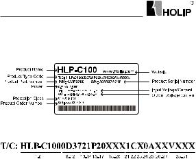
HLP-C100 Series
Chapter 2 Standards and Specifications
2.1 Label Description
Significance of the product type code:
|
1-8 |
HLP-C100 |
Indicate Product Series |
|
|
9-12 |
0D37 |
Indicate0.37KW |
|
|
13-14 |
21 |
Indicate1-Phase |
AC 220V |
|
23 |
Indicate 3-Phase |
AC 220V |
|
|
43 |
Indicate 3-Phase |
AC 380V |
|
|
15-17 |
P20 |
IP rating is 20 |
|
|
18 |
X |
Without AC choke |
|
|
A |
With AC choke |
||
|
19 |
X |
Without Brake unit |
|
|
B |
With Brake unit |
||
|
20 |
X |
Without DC choke |
|
|
B |
With DC choke |
||
|
21 |
1 |
Control panel with LED display and potentiometer |
|
|
22 |
C |
With coating on PCB |
|
|
23 |
X |
Reserved |
|
|
24 |
0 |
Domestic sale |
|
|
1 |
Overseas sale |
||
|
25 |
A |
Without RS485 |
|
|
B |
With RS485 |
||
|
26-27 |
XX |
Reserved |
|
|
28-31 |
VXXX |
Indicate software version number, such as |
|
|
V235means the version number is 2.35. |
Note: Without RS485 is standard configuration, With RS485 is optional, please specif y when ordering.
|
— 4 — |
HLP-C100 Series Operating Manual |

HLP-C100 Series
2.2 Particular Specifications
|
Model |
Input voltage |
Input |
Output |
Rated |
Suitable |
Net |
||
|
current/ |
current/ |
power/ |
motor/ |
weight/ |
||||
|
A |
A |
KW |
KW |
KG |
||||
|
HLP-C1000D3721 |
1×200-240V50/60Hz |
6.1 |
2.2 |
0.37 |
0.37 |
0.84 |
||
|
HLP-C1000D7521 |
1×200-240V50/60Hz |
11.6 |
4.2 |
0.75 |
0.75 |
0.84 |
||
|
HLP-C10001D521 |
1×200-240V50/60Hz |
18.7 |
6.8 |
1.5 |
1.5 |
0.84 |
||
|
HLP-C1000D3723 |
3×200-240V50/60Hz |
3.5 |
2.2 |
0.37 |
0.37 |
0.84 |
||
|
HLP-C1000D7523 |
3×200-240V50/60Hz |
6.7 |
4.2 |
0.75 |
0.75 |
0.84 |
||
|
HLP-C10001D523 |
3×200-240V50/60Hz |
10.9 |
6.8 |
1.5 |
1.5 |
0.84 |
||
|
HLP-C1000D7543 |
3×380-440V50/60Hz |
3.5 |
2.2 |
0.75 |
0.75 |
0.84 |
||
|
3×440-480V50/60Hz |
3.0 |
2.1 |
||||||
|
HLP-C10001D543 |
3×380-440V50/60Hz |
5.9 |
3.7 |
1.5 |
1.5 |
0.84 |
||
|
3×440-480V50/60Hz |
5.1 |
3.4 |
||||||
|
HLP-C10002D243 |
3×380-440V50/60Hz |
8.5 |
5.3 |
2.2 |
2.2 |
0.84 |
||
|
3×440-480V50/60Hz |
7.3 |
4.8 |
||||||
|
2.3 Technical Specifications |
||||||||
|
Item |
Specification |
|||||||
|
Supply voltage |
Single/Three phase200~240V-20%~+10%; |
|||||||
|
Three phase 380~480V -20%~+10%; |
||||||||
|
Power supply |
||||||||
|
Frequency |
48~62Hz; |
|||||||
|
Max. imbalance |
3%; |
|||||||
|
Motor output |
Output voltage |
Three phase 0-100%of supply voltage; |
||||||
|
Output frequency |
0-400Hz; |
|||||||
|
Control mode |
V/F, VVC+; |
|||||||
|
Start torque |
0.5Hz |
150%; |
||||||
|
Overload capacity |
150% 60s; |
|||||||
|
PWM switch frequency |
2~16kHz; |
|||||||
|
Speed setting resolution |
Digital: 0.001Hz; Analogy: 0.5‰ of the |
|||||||
|
Main control |
max. operating frequency ; |
|||||||
|
Speedopen-loop control |
30~4000 rpm:tolerance±8 rpm; |
|||||||
|
functions |
accuracy |
|||||||
|
Cont rol com ma nd |
LCP, digital terminal, local bus; |
|||||||
|
source |
||||||||
|
Freq uency set t i ng |
LCP, analog, pulse, local bus; |
|||||||
|
source |
||||||||
|
Ramp control |
Selectable 8-speed steps ramp up and |
|||||||
|
down times0.05-300.00s; |
||||||||
|
HLP-C100 Series Operating Manual |
— 5 — |

HLP-C100 Series
|
Item |
Specification |
||
|
Basic |
Speed Open-loop Control; Process Closed-loop Control; Slip |
||
|
Compensation;Torquecompensation;Automatic Voltage Regulation; |
|||
|
Functions |
V/F Control, DC Brake; Speed Limit; Current Limit; FlyingStart; |
||
|
Reset Function; |
|||
|
Application |
Jogging; Multi-speed |
Control via Digital input; Mechanical |
|
|
Functions |
Braking; UP/DOWN; Catch up/Slow down; Counter. |
||
|
Missing Motor Phase Protection; Low-voltage Protection; Over- |
|||
|
Protection |
voltage Protection; Over-current Protection; Output Phase Loss |
||
|
Protection; Output Short Circuit Protection; Output Grounding |
|||
|
Functions |
Fault Protection;Live Zero Timeout Function;ButtonFreeze; |
||
|
Duplicate Fails; LCP Invalid; LCP Incompatible; Parameter Read- |
|||
|
only; Reference Out of Range; Invalid While Running etc. |
|||
|
5 digital inputs; |
|||
|
Input |
1analog input, both can receive voltage |
||
|
Control |
or current signals. |
||
|
terminals |
Output |
1 relay output; |
|
|
Power supply |
1+10V,max current output10mA; |
||
|
Communication* |
RS+, RS-, max baud rate 38400bit/s; |
||
|
8 segments, 5 numeric |
Display f requency, warnings, status |
||
|
displays |
and so on; |
||
|
Indicator |
Light FWD, REV, HZ, A, RPM display |
||
|
various status of the drive; |
|||
|
Display |
Frequency setting, output f requency, |
||
|
feedback value, output current, DC |
|||
|
Data read-outs |
link voltage, output voltage, output |
||
|
power, input terminals state, output |
|||
|
terminals state, analogue input , |
|||
|
analogue output, 1-10 fault records and |
|||
|
accumulated working time etc.; |
|||
|
Enclosure |
IP20; |
||
|
Ambient temperature |
-10 ~50 , derating use when over 40 ; |
||
|
Humidity |
5%-85% (95% without condensation); |
||
|
Environment |
Vibration test |
1.14g; |
|
|
Max. altitude above sea |
1000m, derating use when more than |
||
|
level |
1000 meters; |
||
|
Motor cable length |
Shield cable: 5 meters, unshield cable: 50 |
||
|
meters; |
|||
|
others |
DC choke |
None; |
|
|
Braking unit |
≥220/380V1.5kWBuilt-in |
||
|
— 6 — |
HLP-C100 Series Operating Manual |
![]()
HLP-C100 Series
2.4 Derating Specifications
Derating for ambient temperature: If the drive is operated over 40 ambient temperature, the continuous output current should be decreased.The drive has been designed for operation at max 50 ambient temperationwith one motor size smaller than normal.Continuous operation at full load at 50 ambient temperation will reduce the lifetime of the drive.
Derating for low air pressure: The cooling capability of air is decreased at low air pressure. Below 1000m altitude no de-rating is necessary but above 1000m the ambient temperature or the maximum output current should be decreased. Dcrease the output by 1% per 100m altitude above 1000m or reduce the max. ambient temperature by 1degree per 200m.
2.5 Accessories
Cradle-01 LCP-02 
Network Cable
CopyCard-01 LCP-03 
|
Model |
Specification |
Remark |
|
|
T h e s t a n d a r d le n g t h of |
|||
|
LCP-02 |
extension cable is 15 meters |
Optional, please specif y |
|
|
when mounting LCP on control |
when ordering |
||
|
cabinet. |
|||
|
LCP-03 has the same installation |
Optional, please specif y |
||
|
LCP-03 |
dimensions with HLP-A control |
||
|
panel (OP-AB01). |
when ordering |
||
|
Cradle-01 |
For LCP-02 installation. |
Optional, please specif y |
|
|
when ordering |
|||
|
CopyCard-01 |
Copy Card can copy parameters |
Optional, please specif y |
|
|
f rom one drive to another. |
when ordering |
||
|
Network |
Connect LCP to the drive when |
Do not offer, self |
|
|
mou nting LCP on cont rol |
|||
|
Cable |
cabinet. |
procurement |
|
|
HLP-C100 Series Operating Manual |
— 7 — |
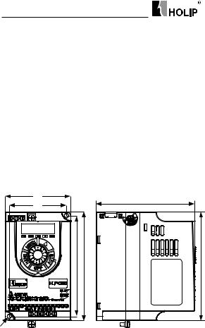
HLP-C100 Series
Chapter 3 Mechanical and Electrical Installation
3.1Mechanical Installation
3.1.1Installation Environment Requirements
1 Ambient temperature in the range of -10 ~ 50 ;
2 Drive should be installed on surface of flame retardant object, with adequate surroundingspace for heat dissipation;
3 Installation should be performed where vibration is less than 1.14g; 4 Avoid from moisture and direct sunlight;
5 Do not expose to an atmosphere with flammable gases, corrosive gases, explosive gasesor other harmful gases;
6 Protect the cooling fan by avoiding oil, dust and metal particles;
7 Prevent drilling residues, wire ends and screws falling into drive;
3.1.2 External and Installation Dimensions
Single/three phase 220V 0.37~1.5kW and three phase 380V 0.75~2.2kW
|
— 8 — |
HLP-C100 Series Operating Manual |

HLP-C100 Series
External and installation dimensions(unit:mm)
|
Model |
A |
B |
C |
D |
E |
F |
|
HLP-C1000D3721 |
||||||
|
HLP-C1000D7521 |
||||||
|
HLP-C10001D521 |
||||||
|
HLP-C1000D3723 |
||||||
|
HLP-C1000D7523 |
74 |
85 |
130 |
140 |
127 |
5 |
|
HLP-C10001D523 |
||||||
|
HLP-C1000D7543 |
||||||
|
HLP-C10001D543 |
||||||
|
HLP-C10002D243 |
3.1.3 Installation and Direction
1. Single Installation
The drive must be installed vertically with smooth ventilation. Enough space must be left around the drive to ensure good cooling, as shown below (unit: mm):
|
HLP-C100 Series Operating Manual |
— 9 — |
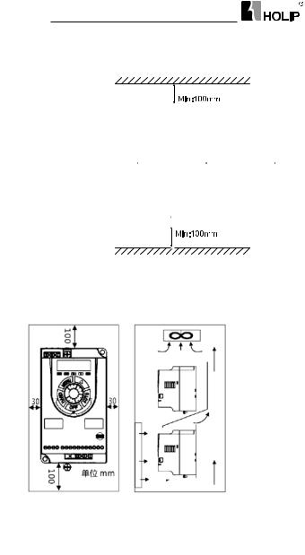
HLP-C100 Series
2. Side by Side Installation
The drive can be mounted side by side, a minimum space must be reserved above and below the enclosure, as shown below:
3.Upper and Lower Installation
If several drives need to be installed together in one cabinet, upper and lower installation can be adopted. Enough space must be reserved to ensure effective cooling, as shown below:
|
— 10 — |
HLP-C100 Series Operating Manual |
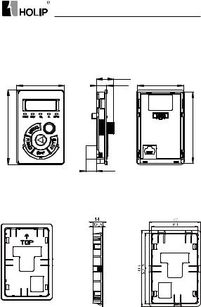
HLP-C100 Series
3.1.4 Accessories Installation
1. LCP-02 Installation
The external dimensions of LCP-02 are shown below (unit: mm):
|
21.7 |
57.1 |
|
|
59.5 |
12.8 |
|
| <![if ! IE]>
<![endif]>92.6 |
<![if ! IE]>
<![endif]>89.2 |
|
|
13.3 |
When installing LCP-02 outside, a cradle is needed. The external dimensions of the cradle are shown below (unit: mm):
|
HLP-C100 Series Operating Manual |
— 11 — |
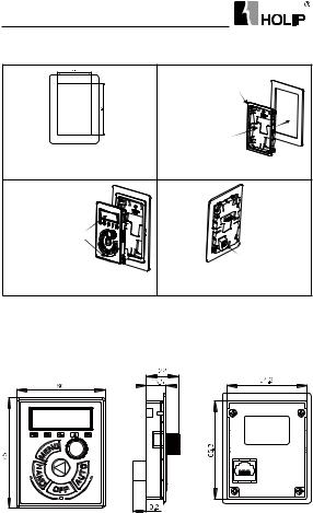
HLP-C100 Series
The installation steps of LCP-02 are shown below:
|
This cradle is suitable for 1.0-2.0mm |
|
|
t hick ness sheet |
|
|
metal parts |
|
|
Press and hold |
|
|
the snap roots when |
|
|
installation, using |
|
|
buckle deformation |
|
|
Step1: Open a hole in line with the size of |
install sheet metal. |
|
the control panel in the position need to |
Step2:Install the LCP according to |
|
install the LCP, holesize,asshown: |
the direction of the arrow. |
|
Recommended |
|
|
to install vertical |
|
|
mounting position |
|
|
arrow, press with |
|
|
uniform force. |
|
|
Step 3:The LCP is installed in the cradle, |
Step4:Install theexternal LCPcommunication |
|
cable,insertintoRJ45terminalfrom thebottom |
|
|
according to the direction of the arrow. |
of hole. |
2. LCP-03 Installation
The external dimensions of LCP-03 are shown below (unit: mm):
|
— 12 — |
HLP-C100 Series Operating Manual |
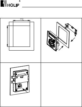
HLP-C100 Series
The installation steps of LCP-03 are shown below:
Step 1: Open a hole in the control panel where it is needed to install LCP-01 or LCP-02, the hole size is as shown.
Step 3: Install the LCP commun-ication cable, insert into RJ45 terminal from the bottom hole.
|
HLP-C100 Series Operating Manual |
— 13 — |
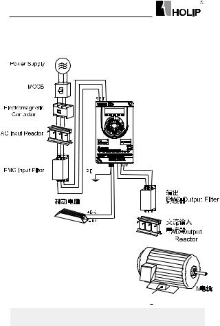
HLP-C100 Series
3.2 Peripheral Electrical Devices
The peripheral electrical devices of the drive are shown below:
|
Part |
Mounting |
Function Description |
|||||||||||
|
Location |
|||||||||||||
|
MCCB |
Power |
Interrupt the power supply when |
|||||||||||
|
receiving side |
overcurrent occurs ondownstream devices. |
||||||||||||
|
Between |
Do not start and stop the drive frequently |
||||||||||||
|
Contactor |
MCCB and |
by switchingthe contactor on and off (less |
|||||||||||
|
drive input |
than twice per minute) noruse it to directly |
||||||||||||
|
side |
start the drive. |
||||||||||||
|
— 14 — |
HLP-C100 Series Operating Manual |

|
HLP-C100 Series |
|||||
|
Part |
Mounting |
Function Description |
|||
|
Location |
|||||
|
Improve the power factor of the input side; |
|||||
|
Eliminate the input current unbalance due |
|||||
|
AC input |
Drive input |
to unbalancebetween the power phases; |
|||
|
Eliminate the higher harmonics of the input |
|||||
|
reactor |
side |
||||
|
sideeffectively; |
|||||
|
prevent other devices from beingdamaged |
|||||
|
due to distortion of the voltage waveform; |
|||||
|
Decrease the conduction interference |
|||||
|
flowing from the power end to the drive and |
|||||
|
EMC input |
Drive input |
improve the antiinterference capacity of the |
|||
|
drive; |
|||||
|
filter |
side |
||||
|
Reduce the external conduction and |
|||||
|
radiation |
|||||
|
interference of the drive; |
|||||
|
Braking |
≥1.5kW |
||||
|
unit |
Braking unit |
Consume the motor feedback energy to |
|||
|
Braking |
is standard |
achieve rapid braking. |
|||
|
resistor |
configuration |
||||
|
EMC |
Drive output |
Reduce the external conduction and |
|||
|
output |
radiation |
||||
|
side |
|||||
|
filter |
interference of the drive. |
||||
|
Between the |
Degrade the motor insulation performance |
||||
|
drive |
and damage the motor in the long run; |
||||
|
AC output |
output side and |
Generate large leakage current and cause |
|||
|
reactor |
the |
frequent ACdrive protection trips; |
|||
|
motor, close to |
If the distance between the drive and the |
||||
|
the |
motor isgreater than 100 m, install an AC |
||||
|
drive |
output reactor; |
3.2.1 Selection of MCCB/Fuse/Contactor
|
Model |
MCCB (A) |
Fuse (A) |
Contactor (A) |
|
HLP-C1000D3721 |
10 |
10 |
10 |
|
HLP-C1000D7521 |
25 |
25 |
16 |
|
HLP-C10001D521 |
32 |
32 |
25 |
|
HLP-C1000D3723 |
10 |
10 |
10 |
|
HLP-C100 Series Operating Manual |
— 15 — |

HLP-C100 Series
|
HLP-C1000D7523 |
16 |
16 |
10 |
|
HLP-C10001D523 |
25 |
25 |
16 |
|
HLP-C1000D7543 |
10 |
10 |
10 |
|
HLP-C10001D543 |
10 |
10 |
10 |
|
HLP-C10002D243 |
16 |
16 |
10 |
3.2.2 Selection of Braking Unit and Braking Resistor
Users can select different braking resistor for different application, it is calculated as follows. But the resistance should not be less than the minimum recommended in the table, otherwise there is a risk of damage caused by the drive, the power of braking resistor can be greater.the greater system inertia, the short deceleration time, the more frequent braking, the greater the power of the braking resistor, the smaller the braking resistor value.
1.Selection of the Braking resistor value
The braking resistor value R = UDH×UDH ÷(KB×PMN)
UDH is the limit of the DC bus, generally it is 700V for 400V model , 400V for 200V model.
PMN is rated motor power
KB is braking torque coefficient, it is between 0.8 to 2.0. For general machine, it is 1.0, for greaterinertia machine, it is 1.5 to 2.
2.Selection of the Braking resistor power
Braking power: Pb = UDH×UDH÷ R
Theoretically braking resistor power and braking power can be the same, But in actual choice, it will be multiplied by a correction factor, braking resistor power
Pr = a Pb
correction factor: a = 0.12~ 0.9
For not frequent acceleration and deceleration application, a can be set as 0.12, for
frequent acceleration and deceleration application, it should be increased.
3.Recommended selection
|
Model |
Braking resistor |
Braking resistor |
|
|
Recommended Power |
Recommended value |
||
|
HLP-C10001D521 |
300W |
50Ω |
|
|
HLP-C10001D523 |
300W |
50Ω |
|
|
HLP-C10001D543 |
250W |
200Ω |
|
|
HLP-C10002D243 |
500W |
100Ω |
|
|
— 16 — |
HLP-C100 Series Operating Manual |
![]()
HLP-C100 Series
For the power less than 0.75kW (including) models, the selection of braking resistor depends on the selection of braking unit.
3.2.3Selection of AC Input and Output Reactor
1.The guide of AC input reactor selection
|
Ratedcurrent |
Maximum |
Inductance (mH) |
|||
|
Model |
continuous |
||||
|
(A) |
& 3% Impedance |
||||
|
current(A) |
|||||
|
HLP-C1000D3721 |
6 |
9 |
11.64 |
||
|
HLP-C1000D7521 |
12 |
18 |
5.74 |
||
|
HLP-C10001D521 |
19 |
28.5 |
2.87 |
||
|
HLP-C1000D3723 |
3.5 |
5.2 |
11.64 |
||
|
HLP-C1000D7523 |
7 |
10.5 |
5.74 |
||
|
HLP-C10001D523 |
11 |
16.5 |
2.87 |
||
|
HLP-C1000D7543 |
3.5 |
5.2 |
16 |
||
|
HLP-C10001D543 |
6 |
9 |
8 |
||
|
HLP-C10002D243 |
8.5 |
13 |
5.5 |
||
|
2. the guide of AC output reactor selection |
|||||
|
Model |
Rated current |
Saturation |
Inductance (mH) |
||
|
(A) |
current (A) |
& 3% Impedance |
|||
|
HLP-C1000D3721 |
2.5 |
5.3 |
9.78 |
||
|
HLP-C1000D7521 |
5 |
10.6 |
4.82 |
||
|
HLP-C10001D521 |
7.5 |
15.9 |
2.41 |
||
|
HLP-C1000D3723 |
2.5 |
5.3 |
9.78 |
||
|
HLP-C1000D7523 |
5 |
10.6 |
4.82 |
||
|
HLP-C10001D523 |
7.5 |
15.9 |
2.41 |
||
|
HLP-C1000D7543 |
2.3 |
4.8 |
14.39 |
||
|
HLP-C10001D543 |
4 |
8.5 |
7.19 |
||
|
HLP-C10002D243 |
5.6 |
11.9 |
4.9 |
|
HLP-C100 Series Operating Manual |
— 17 — |
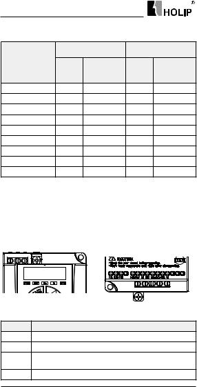
HLP-C100 Series
3.2.4 Selection of EMC Filter
|
EMC Input Filter |
EMC Output Filter |
|||
|
Model |
Rated |
Recommended |
Rated |
Recommended |
|
Current |
Current |
|||
|
(A) |
Model* |
(A) |
Model* |
|
|
HLP-C1000D3721 |
10 |
NFI-010 |
5 |
NFO-005 |
|
HLP-C1000D7521 |
20 |
NFI-020 |
5 |
NFO-005 |
|
HLP-C10001D521 |
20 |
NFI-020 |
10 |
NFO-010 |
|
HLP-C1000D3723 |
5 |
NFI-005 |
5 |
NFO-005 |
|
HLP-C1000D7523 |
10 |
NFI-010 |
5 |
NFO-005 |
|
HLP-C10001D523 |
10 |
NFI-010 |
10 |
NFO-010 |
|
HLP-C1000D7543 |
5 |
NFI-005 |
5 |
NFO-005 |
|
HLP-C10001D543 |
5 |
NFI-005 |
5 |
NFO-005 |
|
HLP-C10002D243 |
10 |
NFI-010 |
10 |
NFO-010 |
* Recommended models is the Shanghai Eagtop Electronic Technology Co., Ltd. products, websitehttp://www.eagtop.com/
3.3Description of Main Circuit
3.3.1Schematic of Main Circuit Terminals
|
Description of main circuit terminals: |
PE |
|
|
Symbol |
Function |
|
|
R, S, T |
Power input, Single phase connected to R, T |
|
|
U, V, W |
Power output, connect to the motor |
|
|
+BR, -BR |
Connect the brake resistor, make sure to set C02.10, C02.11 |
|
|
etc. |
||
|
PE |
Ground terminal |
|
|
— 18 — |
HLP-C100 Series Operating Manual |

HLP-C100 Series
3.3.2 Main Circuit Terminal Screws and Wiring Recommended
Specifications
|
Input |
Output |
Input and |
Input and |
Ground |
Ground |
|
|
Model |
Output |
Output |
||||
|
Cable |
Cable |
Terminals’ |
Terminals’ |
Terminal |
Terminal |
|
|
(mm2) |
(mm2) |
Screw |
Torque |
|||
|
Screws |
Torque |
|||||
|
HLP-C1000D3721 |
1 |
1 |
M3.5 |
0.8-1.0 |
M4 |
1.0-1.2 |
|
HLP-C1000D7521 |
1.5 |
1 |
M3.5 |
0.8-1.0 |
M4 |
1.0-1.2 |
|
HLP-C10001D521 |
1.5 |
1 |
M3.5 |
0.8-1.0 |
M4 |
1.0-1.2 |
|
HLP-C1000D3723 |
1 |
1 |
M3.5 |
0.8-1.0 |
M4 |
1.0-1.2 |
|
HLP-C1000D7523 |
1 |
1 |
M3.5 |
0.8-1.0 |
M4 |
1.0-1.2 |
|
HLP-C10001D523 |
1.5 |
1 |
M3.5 |
0.8-1.0 |
M4 |
1.0-1.2 |
|
HLP-C1000D7543 |
1 |
1 |
M3.5 |
0.8-1.0 |
M4 |
1.0-1.2 |
|
HLP-C10001D543 |
1 |
1 |
M3.5 |
0.8-1.0 |
M4 |
1.0-1.2 |
|
HLP-C10002D243 |
1 |
1 |
M3.5 |
0.8-1.0 |
M4 |
1.0-1.2 |
Note: This specification is under using single-core line VV and 25 , if use other cables or under higher temperature environment, please refer to electrical manual.
3.4 Description of Control Circuit
3.4.1 Schematic of ControlCircuit Terminals
|
J1 |
||||||||||||||||||||
|
FA |
FB |
FC |
FOR |
FEV |
D11 |
D12 |
D13 |
GND |
+10V |
VI |
RS+ |
RS- |
COM |
|||||||
|
Terminals’ specification: |
||||||||||||||||||||
|
Symbol |
Description |
Specification |
||||||||||||||||||
|
1. Resistive Load: 250VAC 3A/30VDC |
||||||||||||||||||||
|
FA-FB-FC |
Relay output |
3A; |
||||||||||||||||||
|
2. |
Inductive |
Load: 250VAC |
||||||||||||||||||
|
0.2A/24VDC 0.1A (cosφ=0.4); |
||||||||||||||||||||
|
FA-FB: NC, FB-FC: NO |
||||||||||||||||||||
|
1. Logic: |
||||||||||||||||||||
|
FOR, REV, |
>DC19V |
Logic:0; |
||||||||||||||||||
|
Digital input |
<DC14V |
Logic:1; |
||||||||||||||||||
|
DI1, DI2, DI3 |
2. Voltage: DC0~24v; |
|||||||||||||||||||
|
3.Input resistance:5kΩ; |
||||||||||||||||||||
|
4. Input voltage Rang:Max ±30v; |
||||||||||||||||||||
|
HLP-C100 Series Operating Manual |
— 19 — |
HLP-C100 Series
|
GND |
Digital/Analog |
Isolated f rom internal COM. |
|||
|
+10V |
10Vpower supply |
Maxload 10mA, with over load and |
|||
|
short circuit protection f unctions. |
|||||
|
VI can be configurated to 0-20mA or |
|||||
|
VI |
Analog input |
0-10Vby paramters: |
|||
|
1.Input Impedance:about10kΩ; |
|||||
|
2.Input Impedence:≤500Ω; |
|||||
|
RS+, RS- |
RS485 |
Max baud rate:38400bit/s; |
|||
|
communication |
|||||
|
COM |
Digital ground |
Isolated from internal GND; |
|||
|
1 |
2 |
3 |
|||||||||
|
RS485 |
ON |
OFF |
|||||||||
|
J1 |
t e r m i n a t i o n |
||||||||||
|
resistor |
jumper Jumper switch 1-2 connected: ON, |
||||||||||
|
switch |
termination resistor connected; |
||||||||||
|
Jumper switch 2-3 connected: OFF, |
|||||||||||
|
termination resistor not connected, |
|||||||||||
|
default state; |
|||||||||||
|
3.4.2 ControlTerminals’Screws and Wiring Recommended |
|||||||||||
|
Specifications |
|||||||||||
|
Cable types |
Cable specifications |
Torque (n∙m) |
|||||||||
|
(mm2) |
|||||||||||
|
Shielded cables |
0.4 |
0.4 |
|||||||||
|
— 20 — |
HLP-C100 Series Operating Manual |

|
HLP-C100 Series |
||||||||
|
3.4.3 ControlCurcuit Wiring |
||||||||
|
Motor |
||||||||
|
Power |
R |
U |
||||||
|
S |
RFI |
V |
||||||
|
Supply |
T |
W |
||||||
|
RFI |
PE |
|||||||
|
Switch |
||||||||
|
PE |
||||||||
|
Switch Mode |
||||||||
|
Power Supply |
+BR |
|||||||
|
10VDC |
24VDC |
|||||||
|
10mA |
200mA |
Braking |
||||||
|
+10V |
-BR |
Resistor |
||||||
|
0-10V |
VI |
FA |
||||||
|
/4-20mA |
||||||||
|
FB |
Relay |
|||||||
|
FC |
||||||||
|
GND |
||||||||
|
FOR |
24V (NPN) |
RS+ |
||||||
|
REV |
24V (NPN) |
RS485 |
Terminal |
RS485 |
||||
|
Digital |
2 |
Resistor |
||||||
|
Interface |
1 |
RS- |
Communication |
|||||
|
Input |
DI1 |
3 |
||||||
|
24V (NPN) |
||||||||
|
Jumper |
||||||||
|
DI2 |
24V (NPN) |
Switch J1 |
COM |
|||||
|
DI3 |
24V (NPN) |
|||||||
|
3.4.4 |
Digital Input Terminals UsageSpecification |
|||||||
|
Open collector NPN mode wiring |
||||||||
|
External |
+24V |
Drive |
||||||
|
Controller |
||||||||
|
+3.3V |
||||||||
|
Opto- |
||||||||
|
Y1 |
DI1 |
isolator |
||||||
|
GND |
||||||||
|
+3.3V |
||||||||
|
Opto- |
||||||||
|
Yn |
DIn |
isolator |
||||||
|
GND |
||||||||
|
GND |
HLP-C100 only supports this mode.
|
HLP-C100 Series Operating Manual |
— 21 — |

HLP-C100 Series
3.5EMC instructions
3.5.1Introduction to EMC Standard
The HLP-C100 series satisfies the requirements of standardIEC/EN61800-3: 2004 (Adjustable speed electricalpower drive systems part 3:EMC requirements and specific test methods).
3.5.2 Noise Abatement
1.When peripheral equipment and the drive share the power supply of one system, noise from the drive may be transmitted to other equipment in this system via power lines and result in misoperation and/or faults. In such a case, the following measures could be taken: a. Mount input noise filter at input terminalof thedrive;
b. Mount power supply filter at power input terminal of affected equipment;
c. Use isolation transformer to isolate the noise transmission path between other equipment and the drive.
2.As the wiring of peripheral equipment and the drive constitutes a circuit, the unavoidable earthing leakage current of drive will cause equipment misoperation and/or faults. Disconnect the grounding connection of equipment may avoid this misoperation and/or faults.
3.Sensitive equipment and signal lines shall be mounted as far away from drive as possible.
4.Signal lines should be provided with shielded layer and reliably grounded. Alternatively, signal cable could be put into metallic conduits between which the distance shall be no less than 20cm, and shall be kept as far away from drive and its peripheral devices, cables as possible. Never make signal lines in parallel with power lines or bundle them up.
5.Signal lines must orthogonally cross power lines if this cross inevitable.
6.Motor cables shall be placed in thick protective screen like more than 2mm-thick pipelines or buried cement groove, also, power lines can be put into metallic conduit and grounded well with shielded cables.
7.Use 4-core motor cables of which one is grounded at close side of the drive and the other side is connected to motor enclosure.
8.Input and output terminals of drive are respectively equipped with radio noise filter and linear noise filter. For example, ferrite common mode choke can restrain radiation noise of power lines.
|
— 22 — |
HLP-C100 Series Operating Manual |

HLP-C100 Series
3.5.3 Grounding
Recommended ground electrode isshown in the figure below:
|
Drive |
Other |
|||||||||||
|
Devices |
||||||||||||
|
PE |
PE |
|||||||||||
1.Use to the fullest extent the maximum standard size of grounding cables to reduce the impedance of grounding system;
2.Grounding wires should be as short as possible;
3.Grounding point shall be as close to the drive as possible;
4.One wire of 4-core motor cables shall be grounded at the drive side and connected to grounding terminal of motor at the other side. Better effect will be achieved if motor and drive are provided with dedicated ground electrodes;
5.When grounding terminals of various parts of system are linked together, leakage current turns into a noise source that may influence other equipment in the system, thus, grounding terminals of the drive and other vulnerable equipment should be separated;
6.Grounding cable shall be kept away from input& output of noisesensitive equipment.
3.5.4 Leakage Current Suppression
Leakage current passes through the line-to-line and ground distributed capacitors at input & output sides of drive, and its size is associated with the capacitance of distributed capacitor and the carrier f requency. Leakage current is classified into ground leakage current and line-to-line leakage current.
1.Ground leakage current not only circulates inside drive system, but may also influence other equipment via ground loop. Such a leakage current may result in malfunction of RCD and other equipment. The higher the carrier frequency of drive is, the bigger the ground leakage current would be. The longer the motor cables and the bigger the parasitic capacitance are, the bigger the ground leakage current would be. Therefore, the most immediate and effective method for suppression of ground leakage current is to reduce carrier frequency
|
HLP-C100 Series Operating Manual |
— 23 — |

HLP-C100 Series
and minimize the length of motor cables.
2.The higher harmonics of line-to-line leakage current that passes through between cables at output side of drive will accel the aging of cables and may bring about malfunction of other equipment. The higher the carrier frequency of drive is, the bigger the line-to-line leakage current would be. The longer the motor cables and the bigger the parasitic capacitance are, the bigger the line-to-line leakage current would be. Therefore, the most immediate and effective method for suppression of ground leakage current is to reduce carrier requency and minimize the length of motor cable. Line-to- line leakage current can also be effectively suppressed by mounting additional output reactors.
3.For the HLP-C100 serials, it can remove RFI screw to cut RFI filter to reduce the leakage current;
3.5.5 Induction VoltageSuppression
The drive outputs pulse voltage which will form induction voltage in the surface of the motor when the drive is not grounded. The induction voltage can be reduced by connecting the drive’s PE terminal to the motor and closing RFI screws .
|
— 24 — |
HLP-C100 Series Operating Manual |
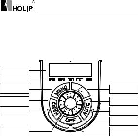
HLP-C100 Series
Chapter 4 Operation and Display Interface
4.1 Local Control Panel
Local Control Panel (LCP)can do the operation of parameters modifications, status monitoring and drive control (start,stop), its appearance isshown blow:
Screen
Functio LED
Menu key
HAND key
HAND LED
Incremental potentiometer
Shift key
AUTO key
AUTO LED
OFF key
OFF LED
1. StateLED
The drive has three operating states: HAND control state, AUTO control state and OFF state. The operating states are indicated by HAND, AUTO and
OFF Led.
HAND LED:The drive is in the HAND control state when it is on. The f requency can be changed by turning the incremental potentiometer. Push
“HAND” key toset the drive in the HANDstate.
OFF Led:The drive is in the OFF state when it is on. Push “OFF” key to set the drive in the HANDstate.
AUTOLED:The drive is in the AUTO state when it is on. In the AUTO state, the drive is controlled by control terminals or communication. Push “AUTO” key to set the drive in the AUTO state.
2. FunctionLed
FWD, REVLed:Indicates that the drive runs forwards or reverse.
Hz, A, RPM Led:Indicates the meaning of data displayed on the screen.
Local remote running lights running lights, OFF LEDs, three LED lights indicate.
|
HLP-C100 Series Operating Manual |
— 25 — |
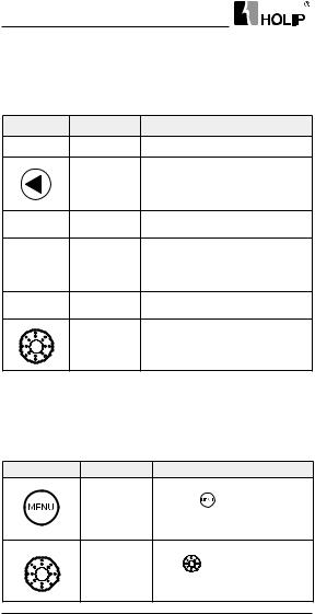
HLP-C100 Series
3. Screen
There are 5 LED which can display reference, output frequency, monitoring data and warning/alarm code.
4. Keys
|
Symbol |
Name |
Function |
|
|
MENU |
Programming |
Enter or exit menu. |
|
|
Select the displayed parameters in |
|||
|
Shift |
turn in the stop or running state; |
||
|
Select the digit to be modified when |
|||
|
modifying parameters. |
|||
|
HAND |
Hand |
Push it to set the drive in the HAND |
|
|
control state. |
|||
|
Stop the drive when it is in the |
|||
|
OFF |
Off/Reset |
running state and perform thereset |
|
|
operation when it is in the fault |
|||
|
state. |
|||
|
AUTO |
Auto |
Push it to set the drive in the AUTO |
|
|
control state. |
|||
|
Push the incremental potentiometer. |
|||
|
Confirm |
Enter the menu or confirm the |
||
|
parameter setting. |
5. Incremental Potentiometer
Increase/decrease data or parameter, clockwise to increase, counterclockwise to decrease.
4.2 ParameterSetting
Example:Set C03.10[0]to 20.5:
|
Key-press |
LCP Display |
Action Description |
|
|
C00.03 |
Presskey |
to display the first |
|
|
basic C00.03 |
|||
|
C03.00 |
Turn |
clockwise to select |
|
|
parameter groupC03 |
|||
|
— 26 — |
HLP-C100 Series Operating Manual |
![]()
|
HLP-C100 Series |
|||
|
C03.00 |
Press |
key to shift to fractional |
|
|
part |
|||
|
C03.10 |
Turn |
clockwise to select |
|
|
parameterC03.10 |
|||
|
[0] |
Press |
key show the first |
|
|
option of C03.10 |
|||
Press key to show the value
0000 of the first option of parameter
C03.10
|
000.5 |
Turn |
clockwise to change the |
|
|
fractional part to 5 |
|||
000.5Press key to shift to integral part
|
020.5 |
Press |
key to change the |
|
|
integral part to 20 |
|||
|
END |
Press |
key to accept the |
|
|
change and save it as 20.5 |
|||
|
HLP-C100 Series Operating Manual |
— 27 — |

HLP-C100 Series
4.3 FWD/REV Status
Confirm the direction of the motor according to the set value, as shown in the following table:
|
Reference: |
Running status |
Indicator Display |
||||
|
≥0 |
STOP |
|||||
|
0 |
STOP |
|||||
|
≥0 |
FWD |
|||||
|
≥0 |
REV |
||||
|
0 |
FWD |
||||
|
0 |
REV |
||||
Note: A flash light denotes the status coming, Light on indicates the current state, and light off means not in this state.
Example 1:The f irst line of the table indicates the drive is stop and the reference is greater than or equal to 0, means the dirve at some time in the f uture will run forward.
Example 2:The fourth line of the table represents the current drive is reverse running, and the reference setting is greater than or equal to 0, it means
|
the drive at some time in the f uture will run forward. |
|
|
— 28 — |
HLP-C100 Series Operating Manual |
 Loading…