
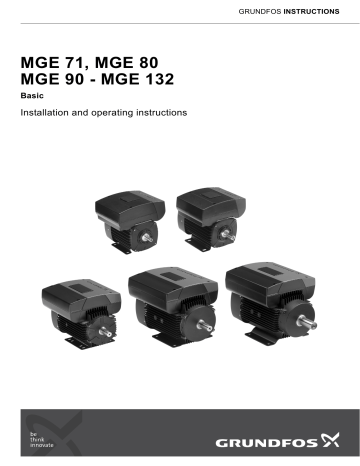
GRUNDFOS INSTRUCTIONS MGE 71, MGE 80 MGE 90 - MGE 132 Basic Installation and operating instructions 1. Symbols used in this document Original installation and operating instructions. CONTENTS Warning Page 1. Symbols used in this document 2 2. General description 2 3. 3.1 Identification Type key 2 3 4. 4.1 4.2 4.3 4.4 4.5 4.6 Installation Handling Motor cooling Outdoor installation Drain holes Cable entries Terminal box position 3 3 3 3 3 3 3 5. 5.1 5.2 5.3 5.4 5.5 5.6 5.7 5.8 Electrical connection - single-phase motors Mains switch Protection against electric shock - indirect contact Additional protection Motor protection Protection against mains voltage transients Supply voltage Start/stop of motor Other connections 4 4 4 4 4 4 4 4 5 6. 6.1 6.2 6.3 6.4 6.5 6.6 6.7 6.8 6.9 Electrical connection - three-phase motors Mains switch Protection against electric shock - indirect contact Additional protection Motor protection Protection against mains voltage transients Protection against phase unbalance Supply voltage Start/stop of motor Other connections 5 5 5 6 6 6 6 6 6 7 7. Signal cables 7 8. 8.1 8.2 Motor control Motor speed control Start/stop input 7 7 7 9. Indicator lights and signal relay 8 10. Megging 9 11. 11.1 11.2 11.3 Technical data - single-phase motors Supply voltage Leakage current Inputs/output 9 9 9 9 12. 12.1 12.2 12.3 Technical data - three-phase motors Supply voltage Leakage current Inputs/output 9 9 9 9 13. Other technical data 13.1 Sound pressure level 10 10 14. 10 Disposal Warning Prior to installation, read these installation and operating instructions. Installation and operation must comply with local regulations and accepted codes of good practice. 2 If these safety instructions are not observed, it may result in personal injury. Caution Note If these safety instructions are not observed, it may result in malfunction or damage to the equipment. Notes or instructions that make the job easier and ensure safe operation. 2. General description Grundfos MGE 71, MGE 80, MGE 90, MGE 100, MGE 112 and MGE 132 are fan-cooled, asynchronous, squirrel-cage motors designed according to current IEC, DIN and VDE guidelines and standards. A frequency converter is integrated in the terminal box. The motors can be used for an open-loop system in which the setpoint signal is used as a control signal. The motor speed and thus the motor output can be remote-controlled by means of an external 0-10 V signal or by a potentiometer. The motors incorporate • inputs for external potential-free contacts for start/stop and an external setpoint signal • an output for a potential-free signal. The motors are only intended for machines with a square torque characteristic, e.g. ventilators or centrifugal pumps. 3. Identification The motor can be identified by means of the nameplate on the terminal box. TM03 0001 3704 English (GB) English (GB) Installation and operating instructions Fig. 1 Nameplate Example MG E 80 - B 2 -19 FT 100 -C 1 Motor Grundfos Electronic control Frame size (centre line height of motor shaft in mm, foot-mounted motor) When the motor is installed in moist surroundings, the bottom drain hole should be open. The enclosure class of the motor is then changed from IP55 to IP44. The function of the drain holes is to drain off water which has entered the stator housing, e.g. condensed water. MGE 71 and MGE 80 The motor has a plugged drain hole on the drive side. The flange can be turned 90 ° to both sides or 180 °. Size of foot: S (small) M (medium) L (large) B14 B5 TM02 9037 1604 B3 Length of stator core: A B C Number of poles: 2 4 6 Fig. 3 Drain holes MGE 90 to MGE 132 B3 mounting Shaft end diameter [mm] The motor has two plugged drain holes on the drive side. The flange can be turned 180 °. Flange version: [ ] (B3) FF (free holes, B5) FT (tapped holes, B14) B14 and B5 mounting The motor has three plugged drain holes on the drive side. The flange can be turned 180 °. Pitch circle diameter [mm] Model designation B3 B14 B5 TM02 9050 1604 Efficiency class: 1 = IE2 motor 3 = IE3 motor [ ] = No efficiency defined (single phase motors) 4. Installation The motor must be secured to a solid foundation by bolts through the holes in the flange or the base plate. Note In order to maintain the UL/cURus approval, additional installation procedures must be followed. See page 11. Fig. 4 Drain holes 4.5 Cable entries MGE 71 and MGE 80 • 2 M16/8 screwed cable entries, cable diameter ∅4 to ∅10. 4.1 Handling • 1 M20/10 screwed cable entry, cable diameter ∅10 to ∅14. Always use the eyebolts fitted in the bores when lifting the motor. MGE 90 to MGE 132 Caution Never lift the motor in the terminal box. 4.2 Motor cooling • 2 M16/8 screwed cable entries, cable diameter ∅4 to ∅10. • 1 M25/6 screwed cable entry, cable diameter ∅9 to ∅17. 4.6 Terminal box position • Place the motor in such a way that sufficient cooling is ensured. • The temperature of the cooling air must not exceed 40 °C. • Cooling fins and fan blades must be kept clean. TM02 9343 2404 To ensure sufficient cooling of motor and electronics, the following must be observed: 4.3 Outdoor installation Fig. 5 Permissible terminal box positions TM00 8622 0101 - TM02 8514 0304 When installed outdoors, the motor must be provided with a suitable cover to avoid condensation on the electronic components. See fig. 2. Fig. 2 Examples of covers 3 English (GB) 4.4 Drain holes 3.1 Type key Caution The user or the installer is responsible for the installation of the correct earthing and protection according to valid national and local standards. All operations must be carried out by a qualified electrician. Warning All electric supply circuits must be interrupted before working in the motor terminal box. Warning Never make any connections in the motor terminal box unless the power supply has been switched off for at least 5 minutes. 5.6 Supply voltage • 1 x 230-240 V - 10 %/+ 10 %, 50/60 Hz, PE • 1 x 200-220 V - 10 %/+ 10 %, 50/60 Hz, PE • 1 x 220-240 V - 10 %/+ 10 %, 50/60 Hz, PE (MGFlex) • 110-415 VDC, PE (MGFlex). The supply voltage and frequency are marked on the motor nameplate. Please make sure that the motor is suitable for the power supply on which it will be used. The wires in the motor terminal box must be as short as possible. Excepted from this is the protective earth conductor which must be so long that it is the last one to be disconnected in case the cable is inadvertently pulled out of the cable entry. For maximum backup fuse, see section 11.1 Supply voltage. MGE 71 and MGE 80 The motor must be connected to an external all-pole mains switch with a contact separation of at least 3 mm in each pole according to IEC 364. 5.2 Protection against electric shock - indirect contact N PE L L PE Fig. 6 Warning N ELCB The motor must be earthed and protected against indirect contact in accordance with national regulations. TM02 0792 0101 5.1 Mains switch Example of a mains-connected motor with mains switch, back-up fuses and additional protection MGE 71 and MGE 80 Protective earth conductors must always have a yellow/green (PE) or yellow/green/blue (PEN) colour marking. N PE L 5.3 Additional protection If the motor is connected to an electric installation where an earth leakage circuit breaker is used as additional protection, this circuit breaker must be marked with the following symbol: ELCB Note When an earth leakage circuit breaker is selected, the total leakage current of all the electrical equipment in the installation must be taken into account. TM02 0796 1504 English (GB) 5. Electrical connection - single-phase motors The leakage current of the motor can be found in section 11.2 Leakage current. 5.4 Motor protection Fig. 7 The motor requires no external motor protection. The motor incorporates thermal protection against slow overloading and blocking (IEC 34-11: TP 211). Mains connection Warning If the supply cable is damaged, it must be replaced by the manufacturer, the manufacturer's service partner or similarly qualified persons in order to avoid a hazard. 5.5 Protection against mains voltage transients The motor is protected against mains voltage transients in accordance with EN 61800-3. 5.7 Start/stop of motor Caution The number of starts and stops via the mains voltage must not exceed 4 times per hour. When the motor is switched on via the mains, it will start after approx. 5 seconds. If a higher number of starts and stops is desired, the input for external start/stop must be used when starting the motor. When the motor is started via an external on/off switch, it will start immediately. 4 The connection terminals of external potential-free contacts for start/stop, external setpoint signal and relay signal are shown in fig. 8. • • The user or the installer is responsible for the installation of the correct earthing and protection according to valid national and local standards. All operations must be carried out by a qualified electrician. Note If no external on/off switch is connected, short-circuit terminals 2 and 3 using a short wire. As a precaution, the wires to be connected to the following connection groups must be separated from each other by reinforced insulation in their entire lengths: Warning Caution Inputs (external start/stop and setpoint signal, terminals 2-6). Warning All inputs (group 1) are internally separated from the mains-conducting parts by reinforced insulation and galvanically separated from other circuits. All control terminals are supplied by protective extra-low voltage (PELV), thus ensuring protection against electric shock. Never make any connections in the motor terminal box unless the power supply has been switched off for at least 5 minutes. All electric supply circuits must be interrupted before working in the motor terminal box. 6.1 Mains switch Output (signal relay, terminals NC, C, NO). The output (group 2) is galvanically separated from other circuits. Therefore, the supply voltage or protective extra-low voltage can be connected to the output as desired. • Caution The motor must be connected to an external all-pole mains switch with a contact separation of at least 3 mm in each pole according to IEC 364. 6.2 Protection against electric shock - indirect contact Mains supply (terminals N, PE, L). Warning A galvanically safe separation must fulfil the requirements for reinforced insulation including creepage distances and clearances specified in EN 61800-5-1. The motor must be earthed and protected against indirect contact in accordance with national regulations. Protective earth conductors must always have a yellow/green (PE) or yellow/green/blue (PEN) colour marking. MGE 71 and MGE 80 N PE L Group 3 Group 2 NC C NO English (GB) 6. Electrical connection - three-phase motors 5.8 Other connections Caution As the leakage current of 4 kW to 7.5 kW motors is > 3.5 mA, these motors must be connected to especially reliable/sturdy earth connections. The leakage current of the motor can be found in section 12.2 Leakage current. EN 50178 and BS 7671 specify the following: Leakage current > 3.5 mA The motor must be stationary and installed permanently. Furthermore, it must be connected permanently to the power supply. • The earth connection must be carried out as duplicate conductors. Leakage current > 10 mA If the installation includes several mains-connected units and the total leakage may be > 10 mA, the demands on the earth connection are tightened. STOP 10K 4: Setpoint input 6 5 4 3 2 Change of direction of rotation Fig. 8 3: GND (frame) 2: Start/stop Group 1 5: +10 V 0-10 V TM02 0839 1504 6: GND (frame) RUN 0/4-20 mA The motor must be stationary and installed permanently. Furthermore, it must be connected permanently to the power supply. In addition, tightened precautions as regards earth connection must be observed. One of the following installation examples must be used: • A single protective earth conductor having a cross-sectional area of 10 mm2. • Separate duplicate conductors each having a minimum cross-sectional area of 4 mm2. • A protective earth conductor contained in a cable conduit, trunking or cable tray so forming a duplicate conductor. Connection terminals 5 6.7 Supply voltage • which is suitable for handling leakage currents and cutting-in with short pulse-shaped leakage. • which trips out when alternating fault currents and fault currents with DC content, i.e. pulsating DC and smooth DC fault currents, occur. For these motors an earth leakage circuit breaker type B must be used. This circuit breaker must be marked with the following symbols: ELCB Note When an earth leakage circuit breaker is selected, the total leakage current of all the electrical equipment in the installation must be taken into account. The leakage current of the motor can be found in section 12.2 Leakage current. • 3 x 380-480 V - 10 %/+ 10 %, 50/60 Hz, PE. The supply voltage and frequency are marked on the motor nameplate. Please make sure that the motor is suitable for the power supply on which it will be used. The wires in the motor terminal box must be as short as possible. Excepted from this is the protective earth conductor which must be so long that it is the last one to be disconnected in case the cable is inadvertently pulled out of the cable entry. For maximum backup fuse, see section 12.1 Supply voltage. MGE 90 to MGE 132 L1 L2 L1 ELCB L2 L3 L3 PE Fig. 9 6.4 Motor protection Example of a mains-connected motor with mains switch, back-up fuses and additional protection The motor requires no external motor protection. The motor incorporates thermal protection against slow overloading and blocking (IEC 34-11: TP 211). MGE 90 to MGE 132 6.5 Protection against mains voltage transients The motor is protected against mains voltage transients in accordance with EN 61800-3. 6.6 Protection against phase unbalance The motor must be connected to an power supply with a quality corresponding to IEC 60146-1-1, class C, to ensure correct motor operation at a phase unbalance. This also ensures long life of the components. PE L3 L2 L1 TM02 9035 1504 English (GB) If the motor is connected to an electric installation where an earth leakage circuit breaker is used as additional protection, this circuit breaker must be of the type: TM00 9270 4696 6.3 Additional protection Fig. 10 Mains connection Warning If the supply cable is damaged, it must be replaced by the manufacturer, the manufacturer's service partner or similarly qualified persons in order to avoid a hazard. 6.8 Start/stop of motor Caution The number of starts and stops via the mains voltage must not exceed 4 times per hour. When the motor is switched on via the mains, it will start after approx. 5 seconds. If a higher number of starts and stops is desired, the input for external start/stop must be used when starting the motor. When the motor is started via an external on/off switch, it will start immediately. 6 The connection terminals of external potential-free contacts for start/stop, external setpoint signal and relay signal are shown in fig. 11. • Use screened cables having a cross-sectional area of min. 0.5 mm2 and max. 1.5 mm2 for external on/off switch and setpoint signal. • The screens of the cables must be connected to frame at both ends with good frame connection. They must be as close as possible to the terminals. See fig. 12. If no external on/off switch is connected, short-circuit terminals 2 and 3 using a short wire. Caution As a precaution, the wires to be connected to the following connection groups must be separated from each other by reinforced insulation in their entire lengths: Inputs (external start/stop and setpoint signal, terminals 2-6). All inputs (group 1) are internally separated from the mains-conducting parts by reinforced insulation and galvanically separated from other circuits. All control terminals are supplied by protective extra-low voltage (PELV), thus ensuring protection against electric shock. • Fig. 12 Stripped cable with screen and wire connection Output (relay signal, terminals NC, C, NO). The output (group 2) is galvanically separated from other circuits. A maximum supply voltage of 250 V or protective extra-low voltage can be connected to the output as desired. • Mains supply (terminals L1, L2, L3, PE). • Screws for frame connections must always be tightened whether a cable is fitted or not. • The wires in the motor terminal box must be as short as possible. 8. Motor control A galvanically safe separation must fulfil the requirements for reinforced insulation including creepage distances and clearances specified in EN 61800-5-1. The motor can be connected to external signals for remote-control of the motor output. 8.1 Motor speed control MGE 90 to MGE 132 The motor speed can be set via the setpoint input, terminal 4. L1 L2 L3 Group 3 Group 2 NC C NO It is possible to use either a 0-10 V signal or a potentiometer. The motor speed can be set within the range from "minimum frequency" to the maximum setpoint of 100 %. 6 5 4 10 k 0 - 10 V + Maximum setpoint 100 % Minimum frequency 0 0 STOP 10K 4: Setpoint input 3: GND (frame) 6 5 4 3 2 Change of direction of rotation Fig. 11 Connection terminals 2: Start/stop TM02 9034 1504 5: +10 V 0-10 V Group 1 0/4-20 mA 10 V 100 % Voltage signal/ potentiometer Fig. 13 Relation between output frequency and external setpoint signal 6: GND (frame) RUN GND (frame) +10 VDC Setpoint input TM02 1326 0901 • Note 8.2 Start/stop input The motor can be started and stopped via an external potential-free contact connected to terminals 2 and 3. Functional diagram: Start/stop input Start/stop (terminals 2 and 3) Normal duty Stop 7 English (GB) 7. Signal cables TM02 1325 0901 6.9 Other connections Green The operating condition of the motor is indicated by the green and red indicator lights in the motor terminal box. See figs 14 and 15. Red Green Signal relay Signal relay TM02 9036 1504 Red TM02 0838 0301 English (GB) 9. Indicator lights and signal relay Fig. 15 Indicator lights and signal relay in three-phase motors Fig. 14 Indicator lights and signal relay in single-phase motors The motor incorporates an output for a potential-free signal via an internal relay. The signal relay is factory-set to "operation". The factory setting can be changed by means of the PC Tool MGE. The functions of the two indicator lights and the factory setting of the signal relay are as shown in the following table: Indicator lights Fault (red) Operation (green) Off Off Off Off Permanently on Permanently on Permanently on Contact position of signal relay The power supply has been switched off. C NO NC C NO NC C NO NC Permanently on The motor is operating. Flashing The motor has been set to stop. Off C NO NC C NO NC Permanently on Flashing NO NC Flashing C NO NC In case of a fault indication, the cause may be one of the following: • The motor has been set to stop, but it has been stopped because of a fault. Three-phase motors only: Internal communication fault. Manual restarting is necessary. A fault indication can be reset in one of the following ways: • By briefly opening the connection between terminals 2 and 3 (stops the motor). • By switching off the power supply until the indicator lights are off. too high motor temperature • undervoltage • overvoltage • too many restarts (after faults) • overload • external fault (e.g. external equipment for dry-running detection) 8 The motor has stopped because of a fault. Restarting will be attempted (it may be necessary to restart the motor by resetting the fault indication). The motor is operating, but it has been stopped because of a fault. C Flashing Description Note 12. Technical data - three-phase motors Megging of an installation incorporating MGE motors is not allowed, as the built-in electronics may be damaged. 12.1 Supply voltage • 3 x 380-480 V - 10 %/+ 10 %, 50/60 Hz, PE. Cable: 6-10 mm2 / 10-8 AWG. See nameplate. 11. Technical data - single-phase motors Recommended fuse size 11.1 Supply voltage • English (GB) 10. Megging Motor size [kW] 1 x 230-240 V - 10 %/+ 10 %, 50/60 Hz, PE Min. [A] Max. [A] • 1 x 200-220 V - 10 %/+ 10 %, 50/60 Hz, PE • 1 x 220-240 V - 10 %/+ 10 %, 50/60 Hz, PE (MGFlex) 0.75 to 3.0 10 16 110-415 VDC, PE (MGFlex). 4.0 to 5.5 16 16 7.5 25 32 • Cable: 1.5 mm2 / 14-12 AWG. See nameplate. Standard as well as quick-blow or slow-blow fuses may be used. Recommended fuse size 12.2 Leakage current Motor size [kW] Min. [A] Max. [A] 0.18 to 0.37 6 10 0.55 to 1.1 10 10 Motor size [kW] Leakage current [mA] 0.75 to 3.0 (supply voltage < 460 V) 0.75 to 3.0 (supply voltage > 460 V) < 3.5 <5 4.0 to 5.5 5.5, 4-pole <5 < 10 7.5 < 10 Standard as well as quick-blow or slow-blow fuses may be used. 11.2 Leakage current Earth leakage current < 3.5 mA. The leakage currents are measured in accordance with EN 60355-1. The leakage currents are measured in accordance with EN 60355-1. 11.3 Inputs/output 12.3 Inputs/output Start/stop Start/stop External potential-free switch. Voltage: 5 VDC. Current: < 5 mA. Screened cable: 0.5 - 1.5 mm2 / 28-16 AWG. External potential-free switch. Voltage: 5 VDC. Current: < 5 mA. Screened cable: 0.5 - 1.5 mm2 / 28-16 AWG. Setpoint signals Setpoint signals • Potentiometer 0-10 VDC, 10 kΩ (via internal voltage supply). Screened cable: 0.5 - 1.5 mm2 / 28-16 AWG. Maximum cable length: 100 m. • Potentiometer 0-10 VDC, 10 kΩ (via internal voltage supply). Screened cable: 0.5 - 1.5 mm2 / 28-16 AWG. Maximum cable length: 100 m. • Voltage signal 0-10 VDC, R i > 50 kΩ. Tolerance: + 0 %/- 3 % at maximum voltage signal. Screened cable: 0.5 - 1.5 mm2 / 28-16 AWG. Maximum cable length: 500 m. • Voltage signal 0-10 VDC, R i > 50 kΩ. Tolerance: + 0 %/- 3 % at maximum voltage signal. Screened cable: 0.5 - 1.5 mm2 / 28-16 AWG. Maximum cable length: 500 m. Signal output Signal output Potential-free changeover contact. Maximum contact load: 250 VAC, 2 A. Minimum contact load: 5 VDC, 10 mA. Screened cable: 0.5 - 2.5 mm2 / 28-12 AWG. Maximum cable length: 500 m. Potential-free changeover contact. Maximum contact load: 250 VAC, 2 A. Minimum contact load: 5 VDC, 10 mA. Screened cable: 0.5 - 2.5 mm2 / 28-12 AWG. Maximum cable length: 500 m. 9 English (GB) 13. Other technical data 14. Disposal EMC (electromagnetic compatibility) This product or parts of it must be disposed of in an environmentally sound way: EN 61800-3. Residential areas - unlimited distribution, corresponding to CISPR 11, class B, group 1. Industrial areas - unlimited distribution, corresponding to CISPR 11, class A, group 1. Contact Grundfos for further information. Enclosure class Standard: IP55 (IEC 34-5). Insulation class F (IEC 85). Ambient temperature • During operation: -20 °C to +40 °C. • During storage/transport: -40 °C to +60 °C. Relative air humidity Maximum 95 %. 13.1 Sound pressure level Single-phase motors < 70 dB(A). Three-phase motors Motor [kW] 0.75 1.1 1.5 2.2 3.0 4.0 5.5 7.5 10 Speed stated on nameplate [min-1] Sound pressure level [dB(A)] 1400-1500 52 2800-3000 63 1400-1500 52 2800-3000 63 1400-1500 53 2800-3000 63 1400-1500 52 2800-3000 64 1400-1500 57 2800-3000 64 1400-1500 59 2800-3000 68 1400-1500 59 2800-3000 68 2800-3000 68 1. Use the public or private waste collection service. 2. If this is not possible, contact the nearest Grundfos company or service workshop. Subject to alterations. 1 1. Installation in the USA and Canada Note In order to maintain the UL/cURus approval, follow these additional installation instructions. The UL approval is according to UL508C. Europe - kW 2-pole 4-pole Fuse size Circuit breaker type/model – 0.55 25 A 25 A / Inverse time 0.75 0.75 25 A 25 A / Inverse time 1.1 Electrical connection 1.1 1.1 25 A 25 A / Inverse time 1.1.1 Conductors 1.5 1.5 25 A 25 A / Inverse time Use 140/167 °F (60/75 °C) copper conductors only. 2.2 2.2 25 A 25 A / Inverse time 1.1.2 Torques 3 3 25 A 25 A / Inverse time Power terminals 4 4 40 A 40 A / Inverse time 5.5 – 40 A 40 A / Inverse time 7.5 5.5 50 A 50 A / Inverse time Motor size [kW] Thread size Torque [Nm] Up to 7.5 kW M4 2.35 11 11 80 A 80 A / Inverse time 11-22 kW M4 Min. 2.2 Max. 2.8 15 15 110 A 110 A / Inverse time 18.5 18.5 125 A 125 A / Inverse time 22 – 150 A 150 A / Inverse time Relay, M2.5: 0.5 Nm. Input control, M2: 0.2 Nm. 1.1.5 Overload protection 1.1.3 Line reactors Max line reactor size must not exceed 2 mH. 1.1.4 Fuse size/circuit breaker If a short circuit happens the pump can be used on a mains supply delivering not more than 5000 RMS symmetrical amperes, 600 V maximum. Fuses When the pump is protected by fuses they must be rated for 480 V. Maximum sizes are stated in table below. Motors up to and including 7.5 kW require class K5 UL-listed fuses. Any UL-listed fuse can be used for motors from 11 to 22 kW. Degree of overload protection provided internally by the drive, in percent of full-load current: 102 %. 1.2 General considerations For installation in humid environment and fluctuating temperatures, it is recommended to keep the pump connected to the power supply continuously. This will prevent moisture and condensation build-up in the terminal box. Start and stop must be done via the start/stop digital input (terminal 2-3). Subject to alterations. Circuit breaker When the pump is protected by a circuit breaker this must be rated for a maximum voltage of 480 V. The circuit breaker must be of the "Inverse time" type. The interrupting rating (RMS symmetrical amperes) must not be less than the values stated in table below. USA - hp 2-pole 4-pole Fuse size Circuit breaker type/model 1 1 25 A 25 A / Inverse time 1.5 1.5 25 A 25 A / Inverse time 2 2 25 A 25 A / Inverse time 3 3 25 A 25 A / Inverse time 5 5 40 A 40 A / Inverse time 7.5 – 40 A 40 A / Inverse time 10 7.5 50 A 50 A / Inverse time 15 15 80 A 80 A / Inverse time 20 20 110 A 110 A / Inverse time 25 25 125 A 125 A / Inverse time 30 – 150 A 150 A / Inverse time 11 Appendix Appendix Declaration of conformity Declaration of conformity 2 GB: EU declaration of conformity BG: Декларация за съответствие на EC We, Grundfos, declare under our sole responsibility that the products MGE 71, MGE 80, MGE 90, MGE 100, MGE 112, MGE 132, to which the declaration below relates, are in conformity with the Council Directives listed below on the approximation of the laws of the EU member states. Ние, фирма Grundfos, заявяваме с пълна отговорност, че продуктите MGE 71, MGE 80, MGE 90, MGE 100, MGE 112, MGE 132, за които се отнася настоящата декларация, отговарят на следните директиви на Съвета за уеднаквяване на правните разпоредби на държавите-членки на EC. CZ: Prohlášení o shodě EU DE: EU-Konformitätserklärung My firma Grundfos prohlašujeme na svou plnou odpovědnost, že výrobky MGE 71, MGE 80, MGE 90, MGE 100, MGE 112, MGE 132, na které se toto prohlášení vztahuje, jsou v souladu s níže uvedenými ustanoveními směrnice Rady pro sblížení právních předpisů členských států Evropského společenství. Wir, Grundfos, erklären in alleiniger Verantwortung, dass die Produkte MGE 71, MGE 80, MGE 90, MGE 100, MGE 112, MGE 132, auf die sich diese Erklärung beziehen, mit den folgenden Richtlinien des Rates zur Angleichung der Rechtsvorschriften der EU-Mitgliedsstaaten übereinstimmen. DK: EU-overensstemmelseserklæring EE: EÜvastavusdeklaratsioon Vi, Grundfos, erklærer under ansvar at produkterne MGE 71, MGE 80, MGE 90, MGE 100, MGE 112, MGE 132 som erklæringen nedenfor omhandler, er i overensstemmelse med Rådets direktiver der er nævnt nedenfor, om indbyrdes tilnærmelse til EU-medlemsstaternes lovgivning. Meie, Grundfos, kinnitame ja kanname ainuisikulist vastutust selle eest, et toode MGE 71, MGE 80, MGE 90, MGE 100, MGE 112, MGE 132, mille kohta all olev deklaratsioon käib, on kooskõlas Nõukogu Direktiividega, mis on nimetatud all pool vastavalt vastuvõetud õigusaktidele ühtlustamise kohta EÜ liikmesriikides. ES: Declaración de conformidad de la UE FI: EU-vaatimustenmukaisuusvakuutus Grundfos declara, bajo su exclusiva responsabilidad, que los productos MGE 71, MGE 80, MGE 90, MGE 100, MGE 112, MGE 132 a los que hace referencia la siguiente declaración cumplen lo establecido por las siguientes Directivas del Consejo sobre la aproximación de las legislaciones de los Estados miembros de la UE. Grundfos vakuuttaa omalla vastuullaan, että tuotteet MGE 71, MGE 80, MGE 90, MGE 100, MGE 112, MGE 132, joita tämä vakuutus koskee, ovat EU:n jäsenvaltioiden lainsäädännön lähentämiseen tähtäävien Euroopan neuvoston direktiivien vaatimusten mukaisia seuraavasti. FR: Déclaration de conformité UE GR: ∆ήλωση συμμόρφωσης ΕΕ Nous, Grundfos, déclarons sous notre seule responsabilité, que les produits MGE 71, MGE 80, MGE 90, MGE 100, MGE 112, MGE 132, auxquels se réfère cette déclaration, sont conformes aux Directives du Conseil concernant le rapprochement des législations des États membres UE relatives aux normes énoncées ci-dessous. Εμείς, η Grundfos, δηλώνουμε με αποκλειστικά δική μας ευθύνη ότι τα προϊόντα MGE 71, MGE 80, MGE 90, MGE 100, MGE 112, MGE 132, στα οποία αναφέρεται η παρακάτω δήλωση, συμμορφώνονται με τις παρακάτω Οδηγίες του Συμβουλίου περί προσέγγισης των νομοθεσιών των κρατών μελών της ΕΕ. HR: EU deklaracija sukladnosti HU: EU megfelelőségi nyilatkozat Mi, Grundfos, izjavljujemo s punom odgovornošću da su proizvodi MGE 71, MGE 80, MGE 90, MGE 100, MGE 112, MGE 132, na koja se izjava odnosi u nastavku, u skladu s direktivama Vijeća dolje navedene o usklađivanju zakona država članica EU-a. Mi, a Grundfos vállalat, teljes felelősséggel kijelentjük, hogy a(z) MGE 71, MGE 80, MGE 90, MGE 100, MGE 112, MGE 132 termékek, amelyre az alábbi nyilatkozat vonatkozik, megfelelnek az Európai Unió tagállamainak jogi irányelveit összehangoló tanács alábbi előírásainak. IT: Dichiarazione di conformità UE LT: ES atitikties deklaracija Grundfos dichiara sotto la sua esclusiva responsabilità che i prodotti MGE 71, MGE 80, MGE 90, MGE 100, MGE 112, MGE 132, ai quale si riferisce questa dichiarazione, sono conformi alle seguenti direttive del Consiglio riguardanti il riavvicinamento delle legislazioni degli Stati membri UE. Mes, Grundfos, su visa atsakomybe pareiškiame, kad produktai MGE 71, MGE 80, MGE 90, MGE 100, MGE 112, MGE 132, kuriems skirta ši deklaracija, atitinka žemiau nurodytas Tarybos Direktyvas dėl ES šalių narių įstatymų suderinimo. LV: ES atbilstības deklarācija NL: EU-conformiteitsverklaring Sabiedrība Grundfos ar pilnu atbildību paziņo, ka produkti MGE 71, MGE 80, MGE 90, MGE 100, MGE 112, MGE 132, uz kuru attiecas tālāk redzamā deklarācija, atbilst tālāk norādītajām Padomes direktīvām par ES dalībvalstu normatīvo aktu tuvināšanu. Wij, Grundfos, verklaren geheel onder eigen verantwoordelijkheid dat de producten MGE 71, MGE 80, MGE 90, MGE 100, MGE 112, MGE 132, waarop de onderstaande verklaring betrekking heeft, in overeenstemming zijn met de onderstaande Richtlijnen van de Raad inzake de onderlinge aanpassing van de wetgeving van de EU-lidstaten. PL: Deklaracja zgodności UE PT: Declaração de conformidade UE My, Grundfos, oświadczamy z pełną odpowiedzialnością, że nasze produkty MGE 71, MGE 80, MGE 90, MGE 100, MGE 112, MGE 132, których deklaracja niniejsza dotyczy, są zgodne z następującymi dyrektywami Rady w sprawie zbliżenia przepisów prawnych państw członkowskich. A Grundfos declara sob sua única responsabilidade que os produtos MGE 71, MGE 80, MGE 90, MGE 100, MGE 112, MGE 132, aos quais diz respeito a declaração abaixo, estão em conformidade com as Directivas do Conselho sobre a aproximação das legislações dos Estados Membros da UE. RO: Declaraţia de conformitate UE RS: Deklaracija o usklađenosti EU Noi Grundfos declarăm pe propria răspundere că produsele MGE 71, MGE 80, MGE 90, MGE 100, MGE 112, MGE 132, la care se referă această declaraţie, sunt în conformitate cu Directivele de Consiliu specificate mai jos privind armonizarea legilor statelor membre UE. Mi, kompanija Grundfos, izjavljujemo pod punom vlastitom odgovornošću da je proizvod MGE 71, MGE 80, MGE 90, MGE 100, MGE 112, MGE 132, na koji se odnosi deklaracija ispod, u skladu sa dole prikazanim direktivama Saveta za usklađivanje zakona država članica EU. RU: Декларация о соответствии нормам ЕС SE: EU-försäkran om överensstämmelse Мы, компания Grundfos, со всей ответственностью заявляем, что изделия MGE 71, MGE 80, MGE 90, MGE 100, MGE 112, MGE 132, к которым относится нижеприведённая декларация, соответствуют нижеприведённым Директивам Совета Евросоюза о тождественности законов стран-членов ЕС. Vi, Grundfos, försäkrar under ansvar att produkterna MGE 71, MGE 80, MGE 90, MGE 100, MGE 112, MGE 132, som omfattas av nedanstående försäkran, är i överensstämmelse med de rådsdirektiv om inbördes närmande till EU-medlemsstaternas lagstiftning som listas nedan. SI: Izjava o skladnosti EU SK: ES vyhlásenie o zhode V Grundfosu s polno odgovornostjo izjavljamo, da je izdelek MGE 71, MGE 80, MGE 90, MGE 100, MGE 112, MGE 132, na katerega se spodnja izjava nanaša, v skladu s spodnjimi direktivami Sveta o približevanju zakonodaje za izenačevanje pravnih predpisov držav članic EU. My, spoločnosť Grundfos, vyhlasujeme na svoju plnú zodpovednosť, že produkty MGE 71, MGE 80, MGE 90, MGE 100, MGE 112, MGE 132 na ktoré sa vyhlásenie uvedené nižšie vzťahuje, sú v súlade s ustanoveniami nižšie uvedených smerníc Rady pre zblíženie právnych predpisov členských štátov EÚ. TR: AB uygunluk bildirgesi UA: Декларація відповідності директивам EU Grundfos olarak, aşağıdaki bildirim konusu olan MGE 71, MGE 80, MGE 90, MGE 100, MGE 112, MGE 132 ürünlerinin, AB Üye ülkelerinin direktiflerinin yakınlaştırılmasıyla ilgili durumun aşağıdaki Konsey Direktifleriyle uyumlu olduğunu ve bununla ilgili olarak tüm sorumluluğun bize ait olduğunu beyan ederiz. Ми, компанія Grundfos, під нашу одноосібну відповідальність заявляємо, що вироби MGE 71, MGE 80, MGE 90, MGE 100, MGE 112, MGE 132, до яких відноситься нижченаведена декларація, відповідають директивам EU, переліченим нижче, щодо тотожності законів країн-членів ЄС. 12 JP: EU 適合宣言 我们,格兰富,在我们的全权责任下声明,产品 MGE 71, MGE 80, MGE 90, MGE 100, MGE 112、MGE 132,即该合格证所指之产品,欧盟使其 成员国法律趋于一致的以下理事会指令。 Grundfos は、その責任の下に、MGE 71, MGE 80, MGE 90, MGE 100, MGE 112、MGE 132 製品が EU 加盟諸国の法規に関連する、以下の評議 会指令に適合していることを宣言します。 KO: EU 적합성 선언 BS: Izjava o usklađenosti EU Grundfos 는 아래의 선언과 관련된 MGE 71, MGE 80, MGE 90, MGE 100, MGE 112, MGE 132 제품이 EU 회원국 법률에 기반하여 아래의 이 사회 지침을 준수함을 단독 책임 하에 선언합니다 . Mi, kompanija Grundfos, izjavljujemo pod vlastitom odgovornošću da je proizvod MGE 71, MGE 80, MGE 90, MGE 100, MGE 112, MGE 132, na koji se odnosi izjava ispod, u skladu sa niže prikazanim direktivama Vijeća o usklađivanju zakona država članica EU. ID: Deklarasi kesesuaian Uni Eropa KZ: Сəйкестік жөніндегі ЕО декларациясы Kami, Grundfos, menyatakan dengan tanggung jawab kami sendiri bahwa produk MGE 71, MGE 80, MGE 90, MGE 100, MGE 112, MGE 132, yang berkaitan dengan pernyataan ini, sesuai dengan Petunjuk Dewan berikut ini serta sedapat mungkin sesuai dengan hukum negara-negara anggota Uni Eropa. Біз, Grundfos, ЕО мүше елдерінің заңдарына жақын төменде көрсетілген Кеңес директиваларына сəйкес төмендегі декларацияға қатысты MGE 71, MGE 80, MGE 90, MGE 100, MGE 112, MGE 132 өнімдері біздің жеке жауапкершілігімізде екенін мəлімдейміз. MK: Декларација за сообразност на ЕУ MY: Perisytiharan keakuran EU Ние, Grundfos, изјавуваме под целосна одговорност дека производите MGE 71, MGE 80, MGE 90, MGE 100, MGE 112, MGE 132, на кои се однесува долунаведената декларација, се во согласност со овие директиви на Советот за приближување на законите на земјите-членки на ЕY. Kami, Grundfos, mengisytiharkan di bawah tanggungjawab kami semata-mata bahawa produk MGE 71, MGE 80, MGE 90, MGE 100, MGE 112, MGE 132, yang berkaitan dengan perisytiharan di bawah, akur dengan Perintah Majlis yang disenaraikan di bawah ini tentang penghampiran undang-undang negara ahli EU. NO: EUs samsvarsærklæring Vi, Grundfos, erklærer under vårt eneansvar at produktene MGE 71, MGE 80, MGE 90, MGE 100, MGE 112, MGE 132 som denne erklæringen gjelder, er i samsvar med styrets direktiver om tilnærming av forordninger i EU-landene. EU إق رار مطابق ة:AR ,MGE 71 بمقتض ى مس ؤوليتنا الفردي ة ب أن المنتجي ن، جرون دفوس،نق ر نح ن الل ذين يخت ص بھم ا،MGE 132 وMGE 80, MGE 90, MGE 100, MGE 112 يكون ان مط ابقين لتوجيھ ات المجل س الم ذكورة أدن اه بش أن ا،باإلق رار أدن اه لتقري .(EU) االتحاد األوروب ي/بي ن ق وانين ال دول أعض اء المجموع ة األوروبي ة TH: คําประกาศความสอดคล องตามมาตรฐาน EU TW: EU 合格聲明 เราในนามของบริ ษั ท Grundfos ขอประกาศภายใต ความรั บผิ ดชอบของเราแต เพี ยงผู เ ดี ยวว าผลิ ตภั ณฑ MGE 71, MGE 80, MGE 90, MGE 100, MGE 112, MGE 132 ซึ่ งเกี่ ยวข องกั บคําประกาศนี้ มี ความสอดคล องกั บระเบี ยบคําสั่ งตามรายการด านล างนี้ ของสภาวิ ชาชี พว าด วยค าประมาณตามกฎหมายของรั ฐที่ เป นสมาชิ ก EU 葛蘭富根據我們唯一的責任,茲聲明與以下聲明相關之 MGE 71, MGE 80, MGE 90, MGE 100, MGE 112、MGE 132 產品,符合下列近似 EU 會員國 法律之議會指令。 VI: Tuyên bố tuân thủ EU AL: Deklara e konformitetit të BE Chúng tôi, Grundfos, tuyên bố trong phạm vi trách nhiệm duy nhất của mình rằng sản phẩm MGE 71, MGE 80, MGE 90, MGE 100, MGE 112, MGE 132 mà tuyên bố dưới đây có liên quan tuân thủ các Chỉ thị Hội đồng sau về việc áp dụng luật pháp của các nước thành viên EU. Ne, Grundfos, deklarojmë vetëm nën përgjegjësinë tonë se produktet MGE 71, MGE 80, MGE 90, MGE 100, MGE 112, MGE 132, me të cilat lidhet kjo deklaratë, janë në pajtueshmëri me direktivat e Këshillit të renditura më poshtë për përafrimin e ligjeve të shteteve anëtare të BE-së. — — Low Voltage Directive (2014/35/EU). Standards used: EN 61800-5-1:2007 EMC Directive (2014/30/EU). Standards used: EN 61800-3:2004+A1:2012 These motors must not be put into service until the machinery into which they are to be incorporated has been declared in conformity with the provisions of the Directive 2006/95. This EU declaration of conformity is only valid when published as part of the Grundfos safety instructions (publication number 96024246 0516). Bjerringbro, 17/3/2016 Zoltán Lajtos Engineering Manager GRUNDFOS Holding A/S Poul Due Jensens Vej 7 8850 Bjerringbro, Denmark Person authorised to compile the technical file and empowered to sign the EU declaration of conformity. 13 Declaration of conformity CN: 欧盟符合性声明 14 Finland Malaysia Spain Bombas GRUNDFOS de Argentina S.A. Ruta Panamericana km. 37.500 Centro Industrial Garin 1619 Garín Pcia. de B.A. Phone: +54-3327 414 444 Telefax: +54-3327 45 3190 OY GRUNDFOS Pumput AB Trukkikuja 1 FI-01360 Vantaa Phone: +358-(0) 207 889 500 Telefax: +358-(0) 207 889 550 Bombas GRUNDFOS España S.A. Camino de la Fuentecilla, s/n E-28110 Algete (Madrid) Tel.: +34-91-848 8800 Telefax: +34-91-628 0465 Australia Pompes GRUNDFOS Distribution S.A. Parc d’Activités de Chesnes 57, rue de Malacombe F-38290 St. Quentin Fallavier (Lyon) Tél.: +33-4 74 82 15 15 Télécopie: +33-4 74 94 10 51 GRUNDFOS Pumps Sdn. Bhd. 7 Jalan Peguam U1/25 Glenmarie Industrial Park 40150 Shah Alam Selangor Phone: +60-3-5569 2922 Telefax: +60-3-5569 2866 GRUNDFOS Pumps Pty. Ltd. P.O. Box 2040 Regency Park South Australia 5942 Phone: +61-8-8461-4611 Telefax: +61-8-8340 0155 Austria GRUNDFOS Pumpen Vertrieb Ges.m.b.H. Grundfosstraße 2 A-5082 Grödig/Salzburg Tel.: +43-6246-883-0 Telefax: +43-6246-883-30 Belgium N.V. GRUNDFOS Bellux S.A. Boomsesteenweg 81-83 B-2630 Aartselaar Tél.: +32-3-870 7300 Télécopie: +32-3-870 7301 Belarus Представительство ГРУНДФОС в Минске 220125, Минск ул. Шафарнянская, 11, оф. 56, БЦ «Порт» Тел.: +7 (375 17) 286 39 72/73 Факс: +7 (375 17) 286 39 71 E-mail: [email protected] Bosna and Herzegovina GRUNDFOS Sarajevo Zmaja od Bosne 7-7A, BH-71000 Sarajevo Phone: +387 33 592 480 Telefax: +387 33 590 465 www.ba.grundfos.com e-mail: [email protected] Brazil France Germany GRUNDFOS GMBH Schlüterstr. 33 40699 Erkrath Tel.: +49-(0) 211 929 69-0 Telefax: +49-(0) 211 929 69-3799 e-mail: [email protected] Service in Deutschland: e-mail: [email protected] Greece GRUNDFOS Hellas A.E.B.E. 20th km. Athinon-Markopoulou Av. P.O. Box 71 GR-19002 Peania Phone: +0030-210-66 83 400 Telefax: +0030-210-66 46 273 Hong Kong GRUNDFOS Pumps (Hong Kong) Ltd. Unit 1, Ground floor Siu Wai Industrial Centre 29-33 Wing Hong Street & 68 King Lam Street, Cheung Sha Wan Kowloon Phone: +852-27861706 / 27861741 Telefax: +852-27858664 Hungary GRUNDFOS Hungária Kft. Park u. 8 H-2045 Törökbálint, Phone: +36-23 511 110 Telefax: +36-23 511 111 BOMBAS GRUNDFOS DO BRASIL Av. Humberto de Alencar Castelo Branco, 630 CEP 09850 - 300 São Bernardo do Campo - SP Phone: +55-11 4393 5533 Telefax: +55-11 4343 5015 India Bulgaria PT. GRUNDFOS POMPA Graha Intirub Lt. 2 & 3 Jln. Cililitan Besar No.454. Makasar, Jakarta Timur ID-Jakarta 13650 Phone: +62 21-469-51900 Telefax: +62 21-460 6910 / 460 6901 Grundfos Bulgaria EOOD Slatina District Iztochna Tangenta street no. 100 BG - 1592 Sofia Tel. +359 2 49 22 200 Fax. +359 2 49 22 201 email: [email protected] Canada GRUNDFOS Canada Inc. 2941 Brighton Road Oakville, Ontario L6H 6C9 Phone: +1-905 829 9533 Telefax: +1-905 829 9512 China GRUNDFOS Pumps (Shanghai) Co. Ltd. 10F The Hub, No. 33 Suhong Road Minhang District Shanghai 201106 PRC Phone: +86 21 612 252 22 Telefax: +86 21 612 253 33 Croatia GRUNDFOS CROATIA d.o.o. Buzinski prilaz 38, Buzin HR-10010 Zagreb Phone: +385 1 6595 400 Telefax: +385 1 6595 499 www.hr.grundfos.com Czech Republic GRUNDFOS s.r.o. Čajkovského 21 779 00 Olomouc Phone: +420-585-716 111 Telefax: +420-585-716 299 Denmark GRUNDFOS DK A/S Martin Bachs Vej 3 DK-8850 Bjerringbro Tlf.: +45-87 50 50 50 Telefax: +45-87 50 51 51 E-mail: [email protected] www.grundfos.com/DK Estonia GRUNDFOS Pumps Eesti OÜ Peterburi tee 92G 11415 Tallinn Tel: + 372 606 1690 Fax: + 372 606 1691 GRUNDFOS Pumps India Private Limited 118 Old Mahabalipuram Road Thoraipakkam Chennai 600 096 Phone: +91-44 2496 6800 Indonesia Ireland GRUNDFOS (Ireland) Ltd. Unit A, Merrywell Business Park Ballymount Road Lower Dublin 12 Phone: +353-1-4089 800 Telefax: +353-1-4089 830 Italy GRUNDFOS Pompe Italia S.r.l. Via Gran Sasso 4 I-20060 Truccazzano (Milano) Tel.: +39-02-95838112 Telefax: +39-02-95309290 / 95838461 Japan GRUNDFOS Pumps K.K. Gotanda Metalion Bldg., 5F, 5-21-15, Higashi-gotanda Shiagawa-ku, Tokyo 141-0022 Japan Phone: +81 35 448 1391 Telefax: +81 35 448 9619 Korea Mexico Bombas GRUNDFOS de México S.A. de C.V. Boulevard TLC No. 15 Parque Industrial Stiva Aeropuerto Apodaca, N.L. 66600 Phone: +52-81-8144 4000 Telefax: +52-81-8144 4010 Netherlands GRUNDFOS Netherlands Veluwezoom 35 1326 AE Almere Postbus 22015 1302 CA ALMERE Tel.: +31-88-478 6336 Telefax: +31-88-478 6332 E-mail: [email protected] New Zealand Sweden GRUNDFOS AB Box 333 (Lunnagårdsgatan 6) 431 24 Mölndal Tel.: +46 31 332 23 000 Telefax: +46 31 331 94 60 Switzerland GRUNDFOS Pumpen AG Bruggacherstrasse 10 CH-8117 Fällanden/ZH Tel.: +41-44-806 8111 Telefax: +41-44-806 8115 Taiwan GRUNDFOS Pumps (Taiwan) Ltd. 7 Floor, 219 Min-Chuan Road Taichung, Taiwan, R.O.C. Phone: +886-4-2305 0868 Telefax: +886-4-2305 0878 Thailand GRUNDFOS Pumps NZ Ltd. 17 Beatrice Tinsley Crescent North Harbour Industrial Estate Albany, Auckland Phone: +64-9-415 3240 Telefax: +64-9-415 3250 GRUNDFOS (Thailand) Ltd. 92 Chaloem Phrakiat Rama 9 Road, Dokmai, Pravej, Bangkok 10250 Phone: +66-2-725 8999 Telefax: +66-2-725 8998 Norway GRUNDFOS POMPA San. ve Tic. Ltd. Sti. Gebze Organize Sanayi Bölgesi Ihsan dede Caddesi, 2. yol 200. Sokak No. 204 41490 Gebze/ Kocaeli Phone: +90 - 262-679 7979 Telefax: +90 - 262-679 7905 E-mail: [email protected] GRUNDFOS Pumper A/S Strømsveien 344 Postboks 235, Leirdal N-1011 Oslo Tlf.: +47-22 90 47 00 Telefax: +47-22 32 21 50 Poland GRUNDFOS Pompy Sp. z o.o. ul. Klonowa 23 Baranowo k. Poznania PL-62-081 Przeźmierowo Tel: (+48-61) 650 13 00 Fax: (+48-61) 650 13 50 Portugal Bombas GRUNDFOS Portugal, S.A. Rua Calvet de Magalhães, 241 Apartado 1079 P-2770-153 Paço de Arcos Tel.: +351-21-440 76 00 Telefax: +351-21-440 76 90 Romania GRUNDFOS Pompe România SRL Bd. Biruintei, nr 103 Pantelimon county Ilfov Phone: +40 21 200 4100 Telefax: +40 21 200 4101 E-mail: [email protected] Russia Turkey Ukraine Бізнес Центр Європа Столичне шосе, 103 м. Київ, 03131, Україна Телефон: (+38 044) 237 04 00 Факс.: (+38 044) 237 04 01 E-mail: [email protected] United Arab Emirates GRUNDFOS Gulf Distribution P.O. Box 16768 Jebel Ali Free Zone Dubai Phone: +971 4 8815 166 Telefax: +971 4 8815 136 United Kingdom GRUNDFOS Pumps Ltd. Grovebury Road Leighton Buzzard/Beds. LU7 4TL Phone: +44-1525-850000 Telefax: +44-1525-850011 U.S.A. ООО Грундфос Россия 109544, г. Москва, ул. Школьная, 39-41, стр. 1 Тел. (+7) 495 564-88-00 (495) 737-30-00 Факс (+7) 495 564 88 11 E-mail [email protected] GRUNDFOS Pumps Corporation 17100 West 118th Terrace Olathe, Kansas 66061 Phone: +1-913-227-3400 Telefax: +1-913-227-3500 Serbia Grundfos Srbija d.o.o. Omladinskih brigada 90b 11070 Novi Beograd Phone: +381 11 2258 740 Telefax: +381 11 2281 769 www.rs.grundfos.com Grundfos Tashkent, Uzbekistan The Representative Office of Grundfos Kazakhstan in Uzbekistan 38a, Oybek street, Tashkent Телефон: (+998) 71 150 3290 / 71 150 3291 Факс: (+998) 71 150 3292 Singapore Addresses Revised 25.01.2016 GRUNDFOS (Singapore) Pte. Ltd. 25 Jalan Tukang Singapore 619264 Phone: +65-6681 9688 Telefax: +65-6681 9689 GRUNDFOS Pumps Korea Ltd. 6th Floor, Aju Building 679-5 Yeoksam-dong, Kangnam-ku, 135-916 Seoul, Korea Phone: +82-2-5317 600 Telefax: +82-2-5633 725 Slovakia Latvia Slovenia SIA GRUNDFOS Pumps Latvia Deglava biznesa centrs Augusta Deglava ielā 60, LV-1035, Rīga, Tālr.: + 371 714 9640, 7 149 641 Fakss: + 371 914 9646 GRUNDFOS LJUBLJANA, d.o.o. Leskoškova 9e, 1122 Ljubljana Phone: +386 (0) 1 568 06 10 Telefax: +386 (0)1 568 06 19 E-mail: [email protected] Lithuania South Africa GRUNDFOS Pumps UAB Smolensko g. 6 LT-03201 Vilnius Tel: + 370 52 395 430 Fax: + 370 52 395 431 GRUNDFOS (PTY) LTD Corner Mountjoy and George Allen Roads Wilbart Ext. 2 Bedfordview 2008 Phone: (+27) 11 579 4800 Fax: (+27) 11 455 6066 E-mail: [email protected] GRUNDFOS s.r.o. Prievozská 4D 821 09 BRATISLAVA Phona: +421 2 5020 1426 sk.grundfos.com Uzbekistan Grundfos companies Argentina ECM: 1183957 www.grundfos.com The name Grundfos, the Grundfos logo, and be think innovate are registered trademarks owned by Grundfos Holding A/S or Grundfos A/S, Denmark. All rights reserved worldwide. 96463446 0516 © Copyright Grundfos Holding A/S
Описание
Спецификация
Наименование продукта MGE71A
№ продукта 98248247
EAN код 5711492052204
Технические данные
Данные на табличке электродвигателя CE,CURUS,EAC
Модель H
Охлаждение IC 411
Cable gland entry 4xM20 заглушка
Монтаж
Диапазон температуры окружающей среды -20 .. 50 °C
Размер фланца электродвигателя FT85
Данные электрооборудования
Стандарт электродвигателя IEC
Тип электродвигателя 71A
Класс энергоэфф-ти IE5
Номинальная мощность — P2 0.55 кВт
Частота питающей сети 50 Hz
Номинальное напряжение 1 x 200-240 В
Номинальный ток 3.45-2.90 A
Cos фи — характеристика мощности 0.98
Номинальная скорость 360-4000 об/м
Номинальный вращающий момент при полной нагрузке 1.8 Нм
Момент инерции 0.0002 кг м²
Энергоэффективность 85.3%
Эффективность электродвигателя при полной нагрузке 85.3 %
Степень защиты (IEC 34-5) IP55
Класс изоляции (IEC 85) F
Встроенная защита электродвигателя ELEC
Тепловая защита ELEC
Монтажн. обозначение по IEC 34-7 IM B14/V18
Bearing insulation type N-end Стальной подшипник
Cable gland entry 4xM20 заглушка
Система управления
Панель управления HMI200 — Стандарт
Общ.модуль НЕТ
Функциональный модуль FM200 — Standard (Стандартный)
Другое
Масса нетто 9 кг
Конфигурац. файл № 98372141
Цвет/Тип NCS 9000 полировка 40+-10 /гальванопокрытие
Технические характеристики «Электродвигатель Grundfos с ЧП MGE71A 2-FT85-HA 1X230 50HZ 0,55kW 98248247»
| Document’s Content and Additional Information | Share Manual |
|---|---|
|
Grundfos MGE 71 Installation and operating instructions manual
Pages Preview: Document Transcription:
See Details |
|
|
Grundfos MGE 71 Installation and operating instructions manual
See Details |
|
|
Grundfos MGE 71 Instructions manual
See Details |
|
|
Grundfos MGE 71 Service instructions manual
See Details |
|
|
Grundfos MGE 71 Installation and operating instructions manual
See Details |
|
|
Grundfos MGE 71 Instructions manual
See Details |


 |
[Page 1] Grundfos MGE Series MGE motors Installation and operating instructions GRUNDFOS INSTRUCTIONS |
 |
[Page 2] Grundfos MGE Series English (GB) 2 English (GB) Installation and operating instructions Original installation and operating instructions CONTENTS Page 1. Symbols used in this document 3 2. Abbreviations and definitions 3 3. General description 4 3.1 Radio communication … |
 |
[Page 3] Grundfos MGE Series English (GB) 3 1. Symbols used in this document 2. Abbreviations and definitions 22. Technical data, single-phase motors 58 22.1 Supply voltage 58 22.2 Leakage current 58 23. Technical data, three-phase motors 58 23.1 Supply voltage 58 23.2 Leakage… |
 |
[Page 4] Grundfos MGE Series English (GB) 4 3. General description Grundfos MGE 71-160 are frequency-controlled permanent-magnet motors for single-phase or three-phase mains connection. The motors incorporate a PI controller. You can connect the motors to a signal from an ex… |
 |
[Page 5] Grundfos MGE Series English (GB) 5 4. Identification You can identify the motor by means of the nameplate on the terminal box. 4.1 Nameplate The motor nameplate is located on the side of the terminal box. See fig. 1, pos. A. Fig. 1 Nameplate location Figure 2 shows t… |
 |
[Page 6] Grundfos MGE Series English (GB) 6 4.2 Type key 1) Frame size 71, 80, 90 2) Frame size 100, 112, 132, 160 Code Example MG E 71 M A 2- FT 85 -H A [ ] B K Type of motor unit Complete motor with terminal box Basic motor unit without terminal box Kit for basic motor unit wi… |
 |
[Page 7] Grundfos MGE Series English (GB) 7 5. Receiving the product 5.1 Transporting the product • Motors from 2.2 to 5.5 kW: Do not stack more than two motors in their original packaging. • Motors from 5.5 to 11 kW: Do not stack the motors. 5.2 Inspecting the product Bef… |
 |
[Page 8] Grundfos MGE Series English (GB) 8 6.5 Outdoor installation If you install the motor outdoors, provide the motor with a suitable cover and open the drain holes to avoid condensation on the electronic components. See figures 4 and 5. The cover must be sufficiently lar… |
 |
[Page 9] Grundfos MGE Series English (GB) 9 7.2 Cable requirements 7.2.1 Cable cross-section Single-phase supply Three-phase supply 7.2.2 Conductors Type Stranded or solid copper conductors. Temperature rating Temperature rating for conductor insulation: 60 °C (140 °F). Tempe… |
 |
[Page 10] Grundfos MGE Series English (GB) 10 7.3.2 Three-phase supply voltage • 3 x 380-500 V — 10 %/+ 10 %, 50/60 Hz, PE. Check that the supply voltage and frequency correspond to the values stated on the nameplate. The wires in the motor terminal box must be as short as po… |
 |
[Page 11] Grundfos MGE Series English (GB) 11 Overload protection If the upper load limit is exceeded, the motor automatically compensates for this by reducing the speed and stops if the overload condition persists. The motor remains stopped for a set period. After this period… |
 |
[Page 12] Grundfos MGE Series English (GB) 12 * If you use an external supply source, there must be a connection to earth. Fig. 10 Connection terminals, FM 100 7.6.2 Standard functional module, FM 200 The module has more inputs and outputs than FM 100 and is suitable for even m… |
 |
[Page 13] Grundfos MGE Series English (GB) 13 * If you use an external supply source, there must be a connection to earth. Fig. 11 Connection terminals, FM 200 TM05 3510 3512 3 15 8 26 23 25 24 7 B Y 6 5 2 4 10 A AI2 GDS RX GDS TX GND GENIbus A GENIbus B +5 V +24 V +24 V GND GEN… |
 |
[Page 14] Grundfos MGE Series English (GB) 14 7.6.3 Advanced functional module, FM 300 The module has a number of inputs and outputs enabling the motor to be used in advanced applications where many inputs and outputs are required. The module has these connections: • three a… |
 |
[Page 15] Grundfos MGE Series English (GB) 15 Terminal Type Function NC Normally closed contact Signal relay 1 (LIVE or PELV) C1 Common NO Normally open contact NC Normally closed contact Signal relay 2 (PELV only) C2 Common NO Normally open contact 18 GND Earth 11 DI4/OC2 Di… |
 |
[Page 16] Grundfos MGE Series English (GB) 16 7.7 Signal cables Use screened cables with a cross-sectional area of minimum 0.5 mm 2 and maximum 1.5 mm 2 for the external on/off switch, digital inputs, setpoint and sensor signals. Connect the screens of the cables to the fra… |
 |
[Page 17] Grundfos MGE Series English (GB) 17 8. Operating conditions 8.1 Maximum number of starts and stops The number of starts and stops via the power supply must not exceed four times per hour. When switched on via the power supply, the motor starts after approximately 5 se… |
 |
[Page 18] Grundfos MGE Series English (GB) 18 9. User interfaces You can make the motor settings by means of the following user interfaces: Control panels • Basic control panel. See section 9.1 Basic control panel. • Standard control panel. See section 9.2 Standard control p… |
 |
[Page 19] Grundfos MGE Series English (GB) 19 9.2 Standard control panel Fig. 18 Standard control panel 9.2.1 Setpoint setting Set the desired setpoint of the motor by pressing or . The green light fields on the control panel indicate the setpoint set. Motor in controlled-op… |
 |
[Page 20] Grundfos MGE Series English (GB) 20 Setting to maximum speed Press continuously to change over to the maximum speed. The top light field flashes. When the top light field is on, press for 3 seconds until the light field starts flashing. To go back, press contin… |
 |
[Page 21] Grundfos MGE Series English (GB) 21 9.3 Advanced control panel The motors can be fitted with the advanced control panel as an option. Fig. 23 Advanced control panel TM05 4849 1013 Pos. Symbol Description 1 Grundfos Eye Shows the operating status of the motor. See s… |
 |
[Page 22] Grundfos MGE Series English (GB) 22 9.3.1 «Home» display Fig. 24 Example of «»Home»» display 9.3.2 Startup guide The motor incorporates a startup guide which is started at the first startup. See section 10.35 «»Run start-up guid… |
 |
[Page 23] Grundfos MGE Series English (GB) 23 9.3.3 Menu overview for advanced control panel 1) Only available if an advanced functional module, type FM 300, is fitted. Advanced control panel «Home» MGE Multimotor system ●● «Status» MGE Multimotor system &… |
 |
[Page 24] Grundfos MGE Series English (GB) 24 Advanced control panel «Settings» MGE Multimotor system Section Page «»Setpoint»» ●●10.1 «»Setpoint»» 32 «»Operating mode»» ●●10.2 «»Operating… |
 |
[Page 25] Grundfos MGE Series English (GB) 25 Continued from page 24. Advanced control panel «Settings» CME Multimotor system Section Page «»Special functions»» ●● «»Ramps»» ●●10.16 «Ramps» 42 «»Stand… |
 |
[Page 26] Grundfos MGE Series English (GB) 26 9.4 Grundfos GO The motor is designed for wireless radio or infrared communication with Grundfos GO. Grundfos GO enables setting of functions and gives access to status overviews, technical product information and actual operating… |
 |
[Page 27] Grundfos MGE Series English (GB) 27 9.4.2 Menu overview for Grundfos GO 1) Only available if an advanced functional module, type FM 300, is fitted. 2) Only available if Grundfos GO is connected to a multimotor system. Dashboard MGE Multimotor system ●● Status MGE Mu… |
 |
[Page 28] Grundfos MGE Series English (GB) 28 Settings MGE Multimotor system Section Page «Setpoint» ●●10.1 «»Setpoint»» 32 «Operating mode» ●●10.2 «»Operating mode»» 32 «Control mode» ●●10.4 «… |
 |
[Page 29] Grundfos MGE Series English (GB) 29 1) Only available if an advanced functional module, type FM 300, is fitted. 2) Only available if Grundfos GO is connected to a multimotor system. Continued from page 29. Settings MGE Multimotor system Section Page «Standstill he… |
 |
[Page 30] Grundfos MGE Series English (GB) 30 9.5 R100 remote control The motor is designed for wireless communication with the Grundfos R100 remote control. Fig. 26 R100 communicating with the motor via infrared light During communication, point R100 at the control panel. Whe… |
 |
[Page 31] Grundfos MGE Series English (GB) 31 Status «Actual setpoint and external setpoint» «Operating mode» «Actual controlled value» «Analog input 1, 2 and 3» «Pt100/1000 input 1 and 2» «Speed» «Power input and p… |
 |
[Page 32] Grundfos MGE Series English (GB) 32 10. Description of functions 10.1 «»Setpoint»» You can set the setpoint for all control modes when you have selected the desired control mode. See section 10.4 «Control mode». 10.2 «»Operating… |
 |
[Page 33] Grundfos MGE Series English (GB) 33 Measured parameter Select one of the parameters listed below, i.e. the parameter to be measured in the system by the sensor connected to the analog input. See fig. 28. Fig. 28 Overview of sensor locations «Unit» «Elec… |
 |
[Page 34] Grundfos MGE Series English (GB) 34 Measured parameter Select one of the parameters listed below, i.e. the parameter to be measured in the system by the Pt100/1000 sensor connected to the Pt100/1000 input. See fig. 29. Fig. 29 Overview of Pt100/1000 sensor locations… |
 |
[Page 35] Grundfos MGE Series English (GB) 35 10.8 «»Digital inputs/outputs»» Available inputs and outputs depend on the functional module fitted in the motor. See section 15. Identification of functional module. You can select if the interface is to be used… |
 |
[Page 36] Grundfos MGE Series English (GB) 36 10.9 «Signal relay» («»Relay outputs»») The motor incorporates two signal relays for potential-free signalling. See section 20. Signal relays. Function You can configure the signal relays to be activate… |
 |
[Page 37] Grundfos MGE Series English (GB) 37 The reading is a percentage of the range between 0 and 200 % of the maximum permissible load at the actual speed. • «»Motor current»» The reading is a percentage of the range between 0 % and 200 % of the rated… |
 |
[Page 38] Grundfos MGE Series English (GB) 38 Example with constant curve with linear influence/function Actual setpoint: actual input signal x (setpoint — user-set minimum speed) + user-set minimum speed. At a user-set minimum speed of 25 %, and a setpoint of 85 % and an ext… |
 |
[Page 39] Grundfos MGE Series English (GB) 39 • «»Inverse with Stop»» and «»Inverse with Min.»» – «»Inverse with Stop»» In the input signal range from 0 to 80 %, the setpoint is influenced inversely. If the input si… |
 |
[Page 40] Grundfos MGE Series English (GB) 40 • «»Influence table with Stop at Max.»» The setpoint is influenced by a curve made out of two to eight points. There is a straight line between the points and a horizontal line before the first point and after… |
 |
[Page 41] Grundfos MGE Series English (GB) 41 10.15 «»Limit-exceeded function»» This function can monitor a measured parameter or one of the internal values such as speed, motor load or motor current. If a set limit is reached, a selected action can take pl… |
 |
[Page 42] Grundfos MGE Series English (GB) 42 10.16 «Ramps» The ramps determine how quickly the motor can accelerate and decelerate during start/stop or setpoint changes. You can set the following: • acceleration time, 0.1 to 300 s • deceleration time, 0.1 to 300 … |
 |
[Page 43] Grundfos MGE Series English (GB) 43 10.21 «Service» «Time to next service» («»Motor bearing service»») This display shows when to replace the motor bearings. The controller monitors the operating pattern of the motor and calcul… |
 |
[Page 44] Grundfos MGE Series English (GB) 44 10.28 «»Delete history»» This menu is only available in the advanced control panel. In this menu, you can delete the following historic data: • «»Delete operating log»». • «»Dele… |
 |
[Page 45] Grundfos MGE Series English (GB) 45 10.35 «»Run start-up guide»» This menu is only available in the advanced control panel. The startup guide automatically starts when you start the motor for the first time. You can always run the startup guide la… |
 |
[Page 46] Grundfos MGE Series English (GB) 46 Advanced control panel 1. Open the «»Assist»» menu. 2. Select «»Assisted pump setup»». 3. Select control mode «»Const. other val.»». 4. Select which analog input to be used a… |
 |
[Page 47] Grundfos MGE Series English (GB) 47 10.42.1 «Alternating operation» Alternating operation functions as a duty/standby operating mode and is possible with two motors of same size and type connected in parallel. The main purpose of the function is to ensure a… |
 |
[Page 48] Grundfos MGE Series English (GB) 48 Grundfos GO and wired motor connection 1. Connect the two motors with each other with a 3-core screened cable between the GENIbus terminals A, Y, B. 2. Power on both motors. 3. Establish contact to one of the motors with Grundfos G… |
 |
[Page 49] Grundfos MGE Series English (GB) 49 Advanced control panel and wired motor connection 1. Connect the two motors with each other with a 3-core screened cable between the GENIbus terminals A, Y, B. 2. Set the needed analog and digital inputs according to the connected… |
 |
[Page 50] Grundfos MGE Series English (GB) 50 12. Priority of settings You can always set the motor to operation at maximum speed or to stop with R100 or Grundfos GO. If two or more functions are enabled at the same time, the motor operates according to the function with th… |
 |
[Page 51] Grundfos MGE Series English (GB) 51 13. Grundfos Eye The operating condition of the motor is indicated by Grundfos Eye on the motor control panel. See fig. 46, pos. A. Fig. 46 Grundfos Eye TM05 4846 2712 A Grundfos Eye Indication Description No lights are on. The po… |
 |
[Page 52] Grundfos MGE Series English (GB) 52 14. Installing a communication interface module Fig. 47 Antistatic service kit 1. Loosen the four screws (fig. 48, A) and remove the terminal box cover (fig. 48, B). Fig. 48 Removing the terminal box cover 2. Remove the CIM cover (f… |
 |
[Page 53] Grundfos MGE Series English (GB) 53 4. Fit the CIM module by aligning it with the three plastic holders (fig. 51, A) and the connecting plug (fig. 51, B). Press home the module using your fingers. Fig. 51 Fitting the CIM module 5. Fit and tighten the securing screw (… |
 |
[Page 54] Grundfos MGE Series English (GB) 54 15. Identification of functional module You can identify the fitted module in one of the following ways: Grundfos GO You can identify the functional module in the «Fitted modules» menu under «Status». Motor disp… |
 |
[Page 55] Grundfos MGE Series English (GB) 55 17. Changing the position of the control panel You can turn the control panel 180 °. Follow the instructions below. 1. Loosen the four screws (TX25) of the terminal box cover. Fig. 57 Loosening the screws 2. Remove the terminal bo… |
 |
[Page 56] Grundfos MGE Series English (GB) 56 6. Fit the terminal box cover, and make sure that it is also turned 180 ° so that the buttons on the control panel are aligned with the buttons on the plastic cover. 7. Tighten the four screws (TX25) with 5 Nm. Fig. 62 Fitting the… |
 |
[Page 57] Grundfos MGE Series English (GB) 57 20. Signal relays The motor has two outputs for potential-free signals via two internal relays. You can set the signal outputs to «Operation», «Running», «Ready», «Alarm» and «Warning&qu… |
 |
[Page 58] Grundfos MGE Series English (GB) 58 21. Megging Do not meg an installation incorporating MGE motors, as the built-in electronics may be damaged. 22. Technical data, single-phase motors 22.1 Supply voltage Single-phase motors are available for the voltages below: • … |
 |
[Page 59] Grundfos MGE Series English (GB) 59 24. Inputs and outputs Earth reference All voltages refer to earth. All currents return to earth. Absolute maximum voltage and current limits Exceeding the following electrical limits may result in severely reduced operating reliab… |
 |
[Page 60] Grundfos MGE Series English (GB) 60 Pt100/1000 inputs (Pt) Temperature range: • Minimum -50 °C (80 Ω/803 Ω). • Maximum 204 °C (177 Ω/1773 Ω). Measurement tolerance: ± 1.5 °C. Measurement resolution: less than 0.3 °C. Automatic range detection (Pt100 or Pt1… |
 |
[Page 61] Grundfos MGE Series English (GB) 61 25.1 Sound pressure level 26. Disposing of the product This product or parts of it must be disposed of in an environmentally sound way: 1. Use the public or private waste collection service. 2. If this is not possible, contact the ne… |
 |
[Page 62] Grundfos MGE Series Appendix 62 Appendix 1 Installation in the USA and Canada For Canada This product complies with the Canadian ICES-003 Class B specifications. This Class B device meets all the requirements of the Canadian interference- causing equipment regulations… |
 |
[Page 63] Grundfos MGE Series Appendix 63 Electrical connection Conductors See section 7.2 Cable requirements, page 9. Torques Maximum tightening torques for the terminals can be found in section Torques, page 60. Line reactors Maximum line reactor size must not exceed 1.5 mH. S… |
 |
[Page 64] Grundfos MGE Series Grundfos companies Argentina Bombas GRUNDFOS de Argentina S.A. Ruta Panamericana km. 37.500 Centro Industrial Garin 1619 Garín Pcia. de B.A. Phone: +54-3327 414 444 Telefax: +54-3327 45 3190 Australia GRUNDFOS Pumps Pty. Ltd. P.O. Box 2040 Regenc… |
 |
[Page 65] Grundfos MGE Series Grundfos companies Malaysia GRUNDFOS Pumps Sdn. Bhd. 7 Jalan Peguam U1/25 Glenmarie Industrial Park 40150 Shah Alam Selangor Phone: +60-3-5569 2922 Telefax: +60-3-5569 2866 Mexico Bombas GRUNDFOS de México S.A. de C.V. Boulevard TLC No. 15 Parque… |
 |
[Page 66] Grundfos MGE Series www.grundfos.com 98246988 0716 ECM: 1188065 The name Grundfos, the Grundfos logo, and be think innovate are registered trademarks owned by Grundfos Holding A/S or Grundfos A/S, Denmark. All rights reserved worldwide. © Copyright Grundfos Holding A/… |