

-
Contents
-
Table of Contents
-
Troubleshooting
-
Bookmarks
Quick Links
Sperry Marine
User, Technical and Service Manual
NAVIGAT X MK 2
Digital Gyrocompass System
Rev. AA, 07 May 2004
056341
Head Office and Freight: Woltmanstrasse 19, D-20097 Hamburg, Germany
Correspondence Address: P.O. Box 10 47 09, D-20032 Hamburg, Germany
Tel.: ++49-40-299 00-0, Fax: ++49-40-299 00-298, E-mail Service: Kai_Stahl@sperry-marine.com
Related Manuals for NORTHROP GRUMMAN Sperry Marine NAVIGAT X MK 2
Summary of Contents for NORTHROP GRUMMAN Sperry Marine NAVIGAT X MK 2
Судовой гирокомпас, точность не менее 0,4°. Отработка до 100 град/сек. Функция автоматической корректировки по скорости судна. Одобрение РРР и РМРС.
Подробнее
Наличие по запросу
Запросить счет на e-mail
Уточнить цену и количество
Отправьте запрос, что бы узнать актуальную цену, наличие нужного количества товара или срок поставки.
Пожалуйста, уточните актуальную цену перед заказом по телефону или электронной почте. Она может отличаться от указанной ввиду резких колебаний курсов валют.
На нашем сайте указаны рекомендованные розничные цены. Для расчета индивидуальных цен и условий, пожалуйста, свяжитесь с нами.
- Описание
- Характеристики
- Отзывы
- Задать вопрос
- Оплата и доставка
Описание
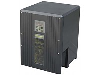
Гирокомпас Sperry Marine NAVIGAT X MK 2
Оптоволоконный гироскопический компас типа моноблок. Работает от сети постоянного тока 24 В с 2 независимыми входами. Сохраняет стабилизацию около 3 минут при отключении питания. Компас оснащен несъемной панелью управления с 4-символьным дисплеем и 6 функциональными кнопками. Скорость отслеживания достигает 100 градусов в секунду. К устройству можно подключить до 4 аналоговых репитеров. Погрешность по широте устраняется с помощью системы двух роторов и жидкостного демпфирования. Время наработки до отказ составляет 40000 часов, техобслуживание компаса выполняется с интервалами 18 месяцев.
Технические характеристики:
- Свобода при бортовой и килевой качке: ±40°;
- Напряжение: 24 В постоянного тока;
- Рабочие температуры: от -10°C to +55°C;
- Время стабилизации: до 3 часов;
- Скорость отслеживания: 100°/с;
- Дисплей: цифровой с 4 символами;
- Наработка на отказ: 40000 часов;
- Потребляемая мощность: 80 Вт при запуске, 45 Вт при работе, 7 Вт через аналоговый ретранслятор;
- Защита: IP23, IEC/EN 60529;
- Размеры: 404х520х420 мм;
- Вес: 25 кг.
Характеристики
|
Производитель |
Sperry Marine |
Задать вопрос
Вы можете задать любой интересующий вас вопрос по товару или работе магазина.
Наши квалифицированные специалисты обязательно вам помогут.
Гирокомпас Navigat X MK2новинка***РМРС***
![]()

- Описание
- Характеристики
NAVIGAT X MK2 является цифровым гирокомпасом, удовлетворяющим международным требованиям для установки на все типы морских судов.
NAVIGAT X MK2 представляет собой компактную систему спроектированную в одном блоке, получающим электропитание 24 В по двум независимым входам.
Изготовленный на базе зарекомендовавшего себя гирокомпаса NAVIGAT X MK1, новый гирокомпас обеспечивает более длительное время работы между техническими сервисами (в среднем 40 000 часов). В случае обесточивания гирокомпас остается в меридиане в течение трех минут.
NAVIGAT X MK2 полностью удовлетворяет требованиям резолюций ИМО A.424(XI) и A.694(17), соответствует стандарту ISO 8728, имеет типовое одобрение Wheelmark.
Изготовлено в соответствии с IMO A.424(XI), A.694(17) и ISO 8728
Типовое одобрение Wheelmark
Один блок
Блок питания: Питание по двум независимым входам
Управление и 4-х строчный дисплейный блок на передней панели с 6 операционными клавишами
Точность направления движения
Статическая секущая широты менее 0.1°
Динамическая секущая широты менее 0.4°
Автоматическая статическая поправка скорости — не требуются дополнительные устройства
Отображение данных об угловой скорости
Высокая скорость передачи данных
Очень точная передача данных направления движения
Автоматическое сличение репитеров посредством последовательного интерфейса IEC-61162-1 / RS422
В случае обесточивания гирокомпас остается в меридиане в течение трех минут
Парные роторы (19000 вращений в минуту) и жидкостная система амортизации устраняют погрешность широты
Длительное время работы между техническим сервисом
Интервалы между техническими сервисами 18 месяцев
Функции мониторинга всей системы с сигнализацией
Простой и не дорогой в обслуживании и ремонте
Длительное хранение операционных данных
Более 250 сервисных центров Sperry Marine по всему миру
Потребление электропитания
|
|---|
Инструкция Гирокомпас Navigat X MK2 Инструкция — Инструкция Гирокомпас Navigat X MK2 Инструкция — Инструкция гирокомпас Navigat X MK2 Инструкция — Инструкция Navigat X MK2 Инструкция — Инструкция X MK2 Инструкция — Омск Гирокомпас Navigat X MK2 Омск — Омск Гирокомпас Navigat X MK2 Омск — Омск гирокомпас Navigat X MK2 Омск — Омск Navigat X MK2 Омск — Омск X MK2 Омск — Купить Гирокомпас Navigat X MK2 Купить — Купить Гирокомпас Navigat X MK2 Купить — Купить гирокомпас Navigat X MK2 Купить — Купить Navigat X MK2 Купить — Купить X MK2 Купить — Буклет Гирокомпас Navigat X MK2 Буклет — Буклет Гирокомпас Navigat X MK2 Буклет — Буклет гирокомпас Navigat X MK2 Буклет — Буклет Navigat X MK2 Буклет — Буклет X MK2 Буклет — Цена Гирокомпас Navigat X MK2 Цена — Цена Гирокомпас Navigat X MK2 Цена — Цена гирокомпас Navigat X MK2 Цена — Цена Navigat X MK2 Цена — Цена X MK2 Цена в Москве, Санкт-Петербурге, Новосибирске, Екатеринбурге, Нижнем Новгороде, Казани, Челябинске, Омске, Самаре, Ростове-на-Дону, Уфе, Красноярске, Перми, Воронеже, Волгограде, Алма-Ате, Астане, Шымкенте, Караганде, Актобе, Таразе, Павлодаре, Усть-Каменогорске, Семее, Костанае, Атырау, Кызылорде, Уральске, Петропавловске, Актау, Темиртау, Туркестане, Кокшетау, Талдыкоргане, Экибастузе, Рудном или любом другом городе России и Казахстана
Контакты

Аккредитованный партнёр серебрянного уровня Motorola

Авторизованный дилер Vertex Standard на территории Сибирского федерального округа.

Авторизованный сервисный центр и региональный дилер компании Samyung ENC Co., Ltd.

Официальный дилер

Авторизированный дилер

Официальный дилер оборудования радиосвязи стандарта TETRA на территории РФ и стран СНГ

Официальный дилер

Официальный дилер
- Каталог/
- Одобренные материалы и изделия Российским Речным Регистром/
- Навигационное оборудование/
- Компасы (магнитные, гиро-, спутниковые)/
- NorthropGrumman SperryMarine Navigat X Mk2
Гироскопический компас Northrop Grumman Sperry Marine Navigat X Mk 2 одобрен Росиийским Речным Регистром и Российским Морским Регистром Судоходства; предназначен для установки на все типы морских судов. Цифровая система гирокомпаса Navigat X Mk 2 является крайне выгодным по цене решением для удовлетворения международных требований по судоходству и перевозке грузов. Компактная, единоблочная конструкция делает Navigat X Mk 2 удобным и простым в установке. Данный гирокомпас может питаться от двух независимых источников постоянного тока с напряжением в 24 Вольта. При разработке Navigat X Mk 2 за основу была взята модель Navigat X Mk 1, таким образом данная модель впитала все лучшее от своего предшественника, например возможность находиться в меридиане при трехминутном сбое в электропитании и мощный ресурс (примерно 40000 часов между тех. обслуживаниями). Navigat X Mk 2 соответствует как нормам A.424(XI) и A.694(17) Международной Морской Организации, так и стандарту 8728 Международной Организации по Стандартизации; имеет типовое одобрение Wheel Mark. Имеет информативный четырехстрочный дисплей. В конструкции Navigat X Mk 2 предусмотрена жидкостная система гашения широтных погрешностей, дополнительный карданный подвес и спаренные роторы.
Особенности гирокомпаса Northrop Grumman Sperry Marine Navigat X Mk 2:
- Компактный моноблок
- 2 независимых источника питания
- Спроектирван и построен на базе Navigat X Mk 1
- Типовое одобрение Wheel Mark
- Четырехстрочный дисплей
- 6 клавиш управления
- Высокая скорость слежения за курсом
- Спаренные роторы
- Точные выходные данные
- Электронный ввод поправок
- Мониторинг всей системы, сигнализация
Спецификации гирокомпаса Northrop Grumman Sperry Marine Navigat X Mk 2:
- Габариты (ШхВхГ мм): 404х520х420
- Вес: 21 кг
- Питание: два 24 VDC
- Потребляемая мощность: старт 80 Вт, режим работы 45 Вт, аналог. репитер 8 Вт
- Слежение за курсом: 100°/сек
- Коррекция в настройках: ±180°
- MTBF: 40000 часов
- Колиество оборотов: 19000 об/мин
- Статическая погрешность < 0.1° sec φ
- Динамическая погрешность < 0.4° sec φ
- Погрешность от пуска к пуску < 0.1° sec φ
Скачать:
Брошюра гирокомпаса Northrop Grumman Sperry Marine Navigat X Mk 2
Гирокомпас Navigat Х
Гирокомпас «Navigat
Х»
— разработка и производство фирмы С. P1ath Navigation Automation, Германия (юридически фирма С. P1ath с 1996 г. входит в объединение Litton, США).
Этот гирокомпас
можно
устанавливать на судах всех типов: от якт до крупных океанских судов.
Гирокомпас «Navigat Х» относится к классу двухгироскопных
гирокомпасов с
автономным чувствительным элементом, имеющим
гидростатический подвес. Существенное конструктивное отличие
этого гирокомпаса (см. рис. 1.10) состоит в способе центрирования чувствительного
элемента (гиросферы ). Центрирование осуществляется с помощью механического, утонченного на конце
стержня (иглы) 3, в который упирается своей камневой опорой 2 гиросфера 1, имеющая
всегда положительную плавучесть. Принципиально новый способ
центрирования, несмотря на значительную технологическую сложность
изготовления этого узла, создает значительные преимущества всех моделей
гирокомпасов фирмы С. P1ath по сравнению с другими двухгироскопными компасами, гиросферы кото-
рых имеют электромаг
нитное или гидродинамическое центрирова
ние. Эти преимущества
состоят:
1)
в сохранении чув
ствительным
элементом положения, близкого к
плоскости истинного меридиана, в
случае перерыва
в судовом питании
в
течение нескольких
минут (при перерыве питания до 3
минут ожидаемая девиация не
превы
сит
2°);
2) в отсутствии не
обходимости
применения системы искусственного
охлаждения под
держивающей
жидкости
или
регулирования ее температуры.
В
том месте, где установлена камневая опора
2 гиросферы 1
(рис.
1.10), реализована подача электропитания на гиромоторы
(одна из трех фаз) с помощью иглы 3
и ртутного контакта 4. Второй ртутный контакт осуществлен нижним полярным электроцом
гиросферы
с
ртутной подушкой 5 (ртутью, налитой на дно следящей сферы). Третья фаза поступает, как обычно через токопроводящую
жидкость на экваториальный электрод гиросферы.
Для работы в условиях особо сильного волнения разработан
гирокомпас «Navigat Х»
mod. 7. Он снабжен резервуаром
(в котором
находится гиросфера), с
дополнительным кардановым подвесом особой конетрукции.
Эта конструкция обеспечивает практически
неограниченную
свободу прокачки резервуару (по крену и диффе
ренту)
до ±90°.
Для
управления работой гирокомпаса и контроля в полной мере
использована микропроцессорная техника.
В базовый комплект гирокомпаса входят два прибора:
основной прибор и электронный блок управления и питания. На рис. 1.11 по
казана
блок-схема соединений приборов комплекта гирокомпаса «Navigat
Х» mod. 10 с периферийными устройствами и приборами,
использующими
информацию о курсе судна.
Ниже
приведены основные технические характеристики этого
гирокомпаса.
Основные технические характеристики гирокомпаса Углы
прокачки
по крену
и дифференту:
«Navigat
Х» mod. 7
«Navigat
Х» mod. 10 ………………………………………..
±35°;
точность:
динамическая погрешность < 0,1°sec ср;
статическая погрешность …………………….. _< 0,7°sec w;
чувствительность следящей системы <_ 0,1°; погрешность в запаздывании при угловой
скорости
поворота судна 6°/с……………………………….. <_
Q1°;
выходная
информация о курсе:
в
аналоговой форме
«Navigat
Х» mod. 7 ………………………………. 300 шагов/°;
«Navigat
Х» mod. 10 ……………………………….. 6 шагов/°;
в
цифровой форме:
«Navigat
Х» mod. 7 ……………………………………. RS 422;
«Navigat Х» mod.
10 ………. NMEA
0183; погрешность гирокомпаса после
3-минутного
перерыва в электропитании …………………. <_ 2°;
быстродействие
следящей системы ……… 10°/с
или 25°/с;
время
прихоца в меридиан ……………………………… менее 3 ч.
В целом эксплуатационные характеристики гирокомпаса соответствуют
требованиям резолюции ИМО А.424 (XI).
Судовой гирокомпас, точность не менее 0,4°. Отработка до 100 град/сек. Функция автоматической корректировки по скорости судна. Одобрение РРР и РМРС.
Подробнее
Наличие по запросу
Запросить счет на e-mail
Уточнить цену и количество
Отправьте запрос, что бы узнать актуальную цену, наличие нужного количества товара или срок поставки.
Пожалуйста, уточните актуальную цену перед заказом по телефону или электронной почте. Она может отличаться от указанной ввиду резких колебаний курсов валют.
На нашем сайте указаны рекомендованные розничные цены. Для расчета индивидуальных цен и условий, пожалуйста, свяжитесь с нами.
- Описание
- Характеристики
- Отзывы
- Задать вопрос
- Оплата и доставка
Описание
Гирокомпас Sperry Marine NAVIGAT X MK 2
Оптоволоконный гироскопический компас типа моноблок. Работает от сети постоянного тока 24 В с 2 независимыми входами. Сохраняет стабилизацию около 3 минут при отключении питания. Компас оснащен несъемной панелью управления с 4-символьным дисплеем и 6 функциональными кнопками. Скорость отслеживания достигает 100 градусов в секунду. К устройству можно подключить до 4 аналоговых репитеров. Погрешность по широте устраняется с помощью системы двух роторов и жидкостного демпфирования. Время наработки до отказ составляет 40000 часов, техобслуживание компаса выполняется с интервалами 18 месяцев.
Технические характеристики:
- Свобода при бортовой и килевой качке: ±40°;
- Напряжение: 24 В постоянного тока;
- Рабочие температуры: от -10°C to +55°C;
- Время стабилизации: до 3 часов;
- Скорость отслеживания: 100°/с;
- Дисплей: цифровой с 4 символами;
- Наработка на отказ: 40000 часов;
- Потребляемая мощность: 80 Вт при запуске, 45 Вт при работе, 7 Вт через аналоговый ретранслятор;
- Защита: IP23, IEC/EN 60529;
- Размеры: 404х520х420 мм;
- Вес: 25 кг.
Характеристики
|
Производитель |
Sperry Marine |
Задать вопрос
Вы можете задать любой интересующий вас вопрос по товару или работе магазина.
Наши квалифицированные специалисты обязательно вам помогут.
Гирокомпас Navigat X MK2новинка***РМРС***
![]()
- Описание
- Характеристики
NAVIGAT X MK2 является цифровым гирокомпасом, удовлетворяющим международным требованиям для установки на все типы морских судов.
NAVIGAT X MK2 представляет собой компактную систему спроектированную в одном блоке, получающим электропитание 24 В по двум независимым входам.
Изготовленный на базе зарекомендовавшего себя гирокомпаса NAVIGAT X MK1, новый гирокомпас обеспечивает более длительное время работы между техническими сервисами (в среднем 40 000 часов). В случае обесточивания гирокомпас остается в меридиане в течение трех минут.
NAVIGAT X MK2 полностью удовлетворяет требованиям резолюций ИМО A.424(XI) и A.694(17), соответствует стандарту ISO 8728, имеет типовое одобрение Wheelmark.
Изготовлено в соответствии с IMO A.424(XI), A.694(17) и ISO 8728
Типовое одобрение Wheelmark
Один блок
Блок питания: Питание по двум независимым входам
Управление и 4-х строчный дисплейный блок на передней панели с 6 операционными клавишами
Точность направления движения
Статическая секущая широты менее 0.1°
Динамическая секущая широты менее 0.4°
Автоматическая статическая поправка скорости — не требуются дополнительные устройства
Отображение данных об угловой скорости
Высокая скорость передачи данных
Очень точная передача данных направления движения
Автоматическое сличение репитеров посредством последовательного интерфейса IEC-61162-1 / RS422
В случае обесточивания гирокомпас остается в меридиане в течение трех минут
Парные роторы (19000 вращений в минуту) и жидкостная система амортизации устраняют погрешность широты
Длительное время работы между техническим сервисом
Интервалы между техническими сервисами 18 месяцев
Функции мониторинга всей системы с сигнализацией
Простой и не дорогой в обслуживании и ремонте
Длительное хранение операционных данных
Более 250 сервисных центров Sperry Marine по всему миру
Потребление электропитания
|
|---|
Инструкция Гирокомпас Navigat X MK2 Инструкция — Инструкция Гирокомпас Navigat X MK2 Инструкция — Инструкция гирокомпас Navigat X MK2 Инструкция — Инструкция Navigat X MK2 Инструкция — Инструкция X MK2 Инструкция — Омск Гирокомпас Navigat X MK2 Омск — Омск Гирокомпас Navigat X MK2 Омск — Омск гирокомпас Navigat X MK2 Омск — Омск Navigat X MK2 Омск — Омск X MK2 Омск — Купить Гирокомпас Navigat X MK2 Купить — Купить Гирокомпас Navigat X MK2 Купить — Купить гирокомпас Navigat X MK2 Купить — Купить Navigat X MK2 Купить — Купить X MK2 Купить — Буклет Гирокомпас Navigat X MK2 Буклет — Буклет Гирокомпас Navigat X MK2 Буклет — Буклет гирокомпас Navigat X MK2 Буклет — Буклет Navigat X MK2 Буклет — Буклет X MK2 Буклет — Цена Гирокомпас Navigat X MK2 Цена — Цена Гирокомпас Navigat X MK2 Цена — Цена гирокомпас Navigat X MK2 Цена — Цена Navigat X MK2 Цена — Цена X MK2 Цена в Москве, Санкт-Петербурге, Новосибирске, Екатеринбурге, Нижнем Новгороде, Казани, Челябинске, Омске, Самаре, Ростове-на-Дону, Уфе, Красноярске, Перми, Воронеже, Волгограде, Алма-Ате, Астане, Шымкенте, Караганде, Актобе, Таразе, Павлодаре, Усть-Каменогорске, Семее, Костанае, Атырау, Кызылорде, Уральске, Петропавловске, Актау, Темиртау, Туркестане, Кокшетау, Талдыкоргане, Экибастузе, Рудном или любом другом городе России и Казахстана
Контакты
Аккредитованный партнёр серебрянного уровня Motorola
Авторизованный дилер Vertex Standard на территории Сибирского федерального округа.
Авторизованный сервисный центр и региональный дилер компании Samyung ENC Co., Ltd.
Официальный дилер
Авторизированный дилер
Официальный дилер оборудования радиосвязи стандарта TETRA на территории РФ и стран СНГ
Официальный дилер
Официальный дилер
- Каталог/
- Одобренные материалы и изделия Российским Речным Регистром/
- Навигационное оборудование/
- Компасы (магнитные, гиро-, спутниковые)/
- NorthropGrumman SperryMarine Navigat X Mk2
Гироскопический компас Northrop Grumman Sperry Marine Navigat X Mk 2 одобрен Росиийским Речным Регистром и Российским Морским Регистром Судоходства; предназначен для установки на все типы морских судов. Цифровая система гирокомпаса Navigat X Mk 2 является крайне выгодным по цене решением для удовлетворения международных требований по судоходству и перевозке грузов. Компактная, единоблочная конструкция делает Navigat X Mk 2 удобным и простым в установке. Данный гирокомпас может питаться от двух независимых источников постоянного тока с напряжением в 24 Вольта. При разработке Navigat X Mk 2 за основу была взята модель Navigat X Mk 1, таким образом данная модель впитала все лучшее от своего предшественника, например возможность находиться в меридиане при трехминутном сбое в электропитании и мощный ресурс (примерно 40000 часов между тех. обслуживаниями). Navigat X Mk 2 соответствует как нормам A.424(XI) и A.694(17) Международной Морской Организации, так и стандарту 8728 Международной Организации по Стандартизации; имеет типовое одобрение Wheel Mark. Имеет информативный четырехстрочный дисплей. В конструкции Navigat X Mk 2 предусмотрена жидкостная система гашения широтных погрешностей, дополнительный карданный подвес и спаренные роторы.
Особенности гирокомпаса Northrop Grumman Sperry Marine Navigat X Mk 2:
- Компактный моноблок
- 2 независимых источника питания
- Спроектирван и построен на базе Navigat X Mk 1
- Типовое одобрение Wheel Mark
- Четырехстрочный дисплей
- 6 клавиш управления
- Высокая скорость слежения за курсом
- Спаренные роторы
- Точные выходные данные
- Электронный ввод поправок
- Мониторинг всей системы, сигнализация
Спецификации гирокомпаса Northrop Grumman Sperry Marine Navigat X Mk 2:
- Габариты (ШхВхГ мм): 404х520х420
- Вес: 21 кг
- Питание: два 24 VDC
- Потребляемая мощность: старт 80 Вт, режим работы 45 Вт, аналог. репитер 8 Вт
- Слежение за курсом: 100°/сек
- Коррекция в настройках: ±180°
- MTBF: 40000 часов
- Колиество оборотов: 19000 об/мин
- Статическая погрешность < 0.1° sec φ
- Динамическая погрешность < 0.4° sec φ
- Погрешность от пуска к пуску < 0.1° sec φ
Скачать:
Брошюра гирокомпаса Northrop Grumman Sperry Marine Navigat X Mk 2
-
8/13/2019 Navigat Mk2 Manual
1/98
Northrop Grumman Sperry Marine B.V. (Representative
Office)Woltmanstr. 19 D-20097 Hamburg, GermanyTel.: +49-40-299 00-0 Fax: +49-40-299 00-146 E-mail:
[email protected]Operation, Installation and Service Manual
NAVIGAT X MK2
Digital Gyrocompass System
Type 4991, Stock No. 74799
056341/C, 08 May 2008
-
8/13/2019 Navigat Mk2 Manual
2/98
056341/C NAVIGAT X MK 2
2008 Northrop Grumman Sperry Marine B.V.This document and the
information herein is the intellectual property of Northrop
GrummanSperry Marine B.V. [NGSM BV] and its associate companies and
may not be copied or repro-duced without the express permission of
NGSM BV.Specifications were correct at time of press but may be
varied in accordance with NGSM BVspolicy of continuous product
development.Any technical content should be verified with NGSM
BV.Sperry Marine, with worldwide headquarters in Charlottesville,
VA, and major engineering andsupport offices in Melville, NY, New
Malden, England, and Hamburg, Germany, is part of theNorthrop
Grumman Electronic Systems sector.Revision Record
Rev. Date Remarks
C 08 May 2008 Added new options (alarm mute relay, speed
filter).B 17 Nov 2006 Removed gyrospere installation/service
instructions. These are nowcontained in separate documents
delivered with the respective gyro-sphere container.
AA 07 May 2004 Initial release
-
8/13/2019 Navigat Mk2 Manual
3/98
NAVIGAT X MK 2 056341/C
i
Safety Instructions
Safety Notice Conventions
The following safety notice conventions are followed throughout
thismanual:DANGER A Dangernotice contains an operating or main-tenance
procedure, practice, condition, state-ment, etc., which, if not
strictly observed, willresult in injury or death of personnel.WARNING A Warningnotice contains an operating ormaintenance
procedure, practice, condition,statement, etc., which, if not
strictly observed,could result in injury or death of personnel.
CAUTION A Cautionnotice contains an operating or main-tenance
procedure, practice, condition, state-ment, etc., which, if not
strictly observed, couldresult in damage to, or destruction of
equip-ment.Note A Notecontains an essential operating or main-tenance
procedure, condition or statement,which is considered important
enough to behighlighted.
Special safety symbols may be used in thismanual to
indicate:Risk of electrical shock.Used in conjunction with a Dangeror
Warningnotice.Electrical components sensitive to electrostaticdischarge.
Used in conjunction with a Cautionnotice.
-
8/13/2019 Navigat Mk2 Manual
4/98
056341/C NAVIGAT X MK 2
ii
General Safety Information for the Operator
WARNING Never rely on one heading source alone to navigate a
vessel.Always confirm the plausibility of the NAVIGAT X MK 2
heading and thespeed and position input data against all available
aids to navigation.WARNING After a power-up from cold, the NAVIGAT X MK 2 requires
a settling timeof three hours before reliable heading data is
available.Power up the system at least three hours before leaving
harbour.Power down the system during long docking periods only.Make
sure that the NAVIGAT X MK 2 has settled before using its headingas
the reference for heading control systems, RADAR, ECDIS, etc.A
magnetic heading source should be made active only in case of
failureof the gyrocompass(es).WARNING Before using this system, operators must be
appropriately trained andfamiliar with the operating procedures and
safety instructions containedin this manual.Keep system manuals in
a well-known, readily available location.CAUTION The supporting fluid in the gyrosphere container will
start freezing attemperatures below 0 C.The NAVIGAT X MK 2 may no
longer be operated when the ambient tem-perature at the gyrocompass
location falls below 10 C while the com-pass is in operation or
when the ambient temperature falls below 0 Cwhile the compass is
not in operation.CAUTION Any service work on the gyrosphere is to be carried out
by authorizedservice personnel only.CAUTION Do not clean the compass housing with organic solvents,
acetone or anyother substance which could damage or discolour
plastic.Use only soapy water or a mild detergent to clean the
compass housing. -
8/13/2019 Navigat Mk2 Manual
5/98
NAVIGAT X MK 2 056341/C
1-iii
General Safety Information for Service Personnel
DANGER When the compass is energized, the gyrosphere operating
voltage of100 VAC @ 337 Hz is present on the master PCB, the
gyrosphere supplylines, and across the gyrosphere contacts.CAUTION The gyrosphere is always to be transported in its
carrying box in the orig-inal transport container.Do not throw or
drop the transport container.The transport container is to be
transported in an upright position only.Carry the carrying box containing the gyrosphere by hand only
and han-dle it with extreme care. Remove the gyroshpere from the
carrying boxonly if required for immediate installation.CAUTION After power-down of the compass system, it may take up
to 45 minutesfor the gyroscopes to stop rotating.During this time,
the container must be handled with extreme care.Should the sphere
touch the wall of the container, the momentum of therotating
gyroscopes will make it topple and damage the center pin.CAUTION The NAVIGAT X MK2 contains electrostatic sensitive
components.Electrostatic discharge may permanently damage components.
When servicing the NAVIGAT X MK 2, take precautions to prevent
elec-trostatic discharge. Avoid touching any of the electronic
circuitry.CAUTION It cannot be guaranteed that parameter settings in the
User and Setupmenus and the entries made in the Magnetic Compass
Calibration tableare left intact when the software is
exchanged.Before exchanging the system software IC, record all
parameter settingsto be able to re-enter them manually, if
required. -
8/13/2019 Navigat Mk2 Manual
6/98
056341/C NAVIGAT X MK 2
1-iv
-
8/13/2019 Navigat Mk2 Manual
7/98
NAVIGAT X MK 2 056341/C
v
Contents
Safety Instructions
Safety Notice
Conventions…………………………………………………………………
iGeneral Safety Information for the Operator
…………………………………….. iiGeneral Safety Information for Service
Personnel…………………………….. iiiChapter 1: Introduction
1.1 Design and Main
Features………………………………………………………………
1-11.2 Operating Principle
………………………………………………………………………..
1-21.3 Example System Configurations
…………………………………………………….
1-3Standalone Gyrocompass/TMC System
…………………………………………. 1-3The NAVIGAT X MK 2 within multicompass systems
……………………….. 1-31.4 Technical
Data………………………………………………………………………………..
1-4Chapter 2: Operation
2.1 Operating Conditions
…………………………………………………………………….
2-12.2 Display and Operating Keys
……………………………………………………………
2-2Control and Display Unit
………………………………………………………………..
2-22.3 External control devices
…………………………………………………………………
2-32.4 Power-up Sequence
……………………………………………………………………….
2-42.5 Selecting the active heading source
………………………………………………. 2-52.6 Adjusting the display
brightness…………………………………………………….
2-52.7 Optional
Functions…………………………………………………………………………
2-6Muting Alarms
Remotely………………………………………………………………..
2-62.8 Operating Menu
…………………………………………………………………………….
2-7Entering and Quitting the Main
Menu…………………………………………….. 2-7Navigating the Menu
……………………………………………………………………..
2-7Selecting Parameter Settings
………………………………………………………….
2-8Editing Parameter Values
……………………………………………………………….
2-82.9 Selecting a Display Data Page
………………………………………………………..2-92.10 Manual Settings Menu
…………………………………………………………………
2-10Manual Settings Overview
…………………………………………………………
2-10Manual Settings Parameters
………………………………………………………
2-122.11 User
Setup…………………………………………………………………………………..
2-15User Setup Overview
…………………………………………………………………
2-15User Setup Parameters
………………………………………………………………
2-16 -
8/13/2019 Navigat Mk2 Manual
8/98
056341/C NAVIGAT X MK 2
vi
Chapter 3: Errors and Alarms
3.1 Alarm Indication
…………………………………………………………………………….3-1Audible
Alarm
Indication………………………………………………………………..3-1Visual Alarm
Indication…………………………………………………………………..
3-13.2 Acknowledging Alarms/Muting the Audible
Alarm………………………….3-2Alarm
Acknowledge……………………………………………………………………….3-2Alarm
Mute
……………………………………………………………………………………3-23.3 Error messages
………………………………………………………………………………3-33.4 Service Info Menu (Service Setup 2)
……………………………………………….3-5Service
Setup 2 Access Code
……………………………………………………….
3-5Service Setup 2
Overview…………………………………………………………….3-6Service Setup 2
Parameters………………………………………………………….3-7Chapter 4: Scheduled Maintenance
4.1 Maintenance by Shipboard Personnel
…………………………………………….4-14.2 Gyrosphere Maintenance Specifications
…………………………………………4-118-Month
Maintenance
…………………………………………………………………..4-1Five-Year
Maintenance……………………………………………………………………4-2Chapter 5: Preventive Maintenance
5.1 Protecting the Gyrosphere from Low
Temperatures…………………………5-1Removing the container
from the compass housing ……………………….. 5-2Parts, materials and tools
required………………………………………………….
5-2Procedure
………………………………………………………………………………………
5-2Re-installing the container in the compass housing
………………………… 5-4Parts, materials and tools required
…………………………………………………. 5-4Procedure
………………………………………………………………………………………
5-4Power-up function test
……………………………………………………………………
5-6Procedure
………………………………………………………………………………………
5-6Chapter 6: Installation
6.1 Mechanical
Installation…………………………………………………………………..6-1Installing
the Compass Housing
……………………………………………………..
6-16.2 Electrical
Installation………………………………………………………………………6-2Wiring
Up the
System…………………………………………………………………….6-26.3 Gyrosphere Installation
………………………………………………………………….6-26.4 Initial System Configuration
…………………………………………………………..6-36.5 Alignment Error Correction
…………………………………………………………….6-5Magnetic
Compass Calibration
……………………………………………………….
6-6 -
8/13/2019 Navigat Mk2 Manual
9/98
NAVIGAT X MK 2 056341/C
vii
Chapter 7: System Configuration
7.1 Configuration Menu (Service Setup
1)……………………………………………. 7-1Setup
Access
Code…………………………………………………………………………
7-1Service-Setup 1 Overview
……………………………………………………………
7-2Service Setup 1 Parameters
…………………………………………………………
7-57.2 Factory Settings Menu (Technical Pages)
……………………………………… 7-12Setup Access
Code……………………………………………………………………….
7-12Technical Pages Overview
………………………………………………………….
7-12Technical Pages Parameters
………………………………………………………..
7-13Chapter 8: Troubleshooting
8.1 Troubleshooting Instructions
………………………………………………………….
8-18.2 Location of Parts on the Master PCB
………………………………………………8-2Exchangeable
Components…………………………………………………………….
8-3Connectors…………………………………………………………………………………….
8-3Test Resistor /
Trimpots…………………………………………………………………..
8-4Diagnostic
LEDs……………………………………………………………………………..
8-4Chapter 9: Corrective Maintenance
9.1 Exchanging the System Software
…………………………………………………..9-19.2 Replacing Socketed ICs
………………………………………………………………….
9-2Appendix
A Setup and Configuration Tables
B Drawings
-
8/13/2019 Navigat Mk2 Manual
10/98
056341/C NAVIGAT X MK 2
viii
-
8/13/2019 Navigat Mk2 Manual
11/98
NAVIGAT X MK 2 056341/C
Design and Main Features 1-1
Chapter 1: Introduction
1.1 Design and Main Features
The NAVIGAT X MK2 is a microprocessor controlled marine
gyrocom-pass system with integrated automatic North speed error
correction.The system complies with IMO resolutions A.424(IX) and A.694(17)
andwith EN ISO 8728.The NAVIGAT X MK2 has been type approved by the German
FederalMaritime and Hydrographic Agency (BSH), in accordance with
theMarine Equipment Directive (MED) 96/98/EC, as modified by
Directive2002/75/EC.The single unit design with a polyurethane hard foam housing
allowsthe gyrocompass to be installed on any bridge. If required, an
optionalremote operating unit may be installed.The unique method of supporting the gyrosphere by means of
merebuoyancy ensures North stabilisation during short power
failures. E.g.,after a three minute loss of power, no more than two
degrees of devia-tion may be expected. Once power has been
restored, the gyrocompasswill return quickly to the correct
heading. The combined effects of thetwin rotors and the liquid
damping system virtually eliminate latitudeerror.Heading is measured as a 13-bit absolute value with a digital
shaftencoder. The high-speed follow-up system (follow-up speed up to
100/s) ensures that accurate heading and rate of turn data is
provided underall operating conditions.Integrated monitoring of the supply powers, gyroscope current
and thefollow-up system ensure secure and trouble-free
operation. -
8/13/2019 Navigat Mk2 Manual
12/98
056341/C NAVIGAT X MK 2
1-2 Operating Principle
1.2 Operating Principle
The north-seeking element used in the NAVIGAT X MK 2 system is
thegyrosphere, a hermetically sealed unit with a funnel-shaped
recess,reaching from the outer skin down to its center.Inside the
gyrosphere, two mechanically linked gyroscopes aremounted with their spin axes horizontal in a carrying frame. The
gyro-scopes are allowed to turn around the vertical, but torsion
bands effect adefined rest position, while a mechanical linkage
ensures that the result-ant spin vector of the gyros remains
stationary relative to the gyro-sphere. This twin gyro arrangement
eliminates intercardinal roll error.Once the gyros have run up to
speed, their resultant spin vector, andwith it the sphere, settles
in the direction of true North.Figure 1-1:
The gyrosphere
The top of the gyrosphere contains an annular damping trough,
halffilled with a viscous fluid. The fluid damps azimuthal
oscillations of thegyroscope system. The oscillation period is
tuned to the Schuler periodof 84.4 minutes, so that heading errors
during horizontal accelerationdue to changes in speed and/or
direction are prevented.The gyrosphere floats in a supporting fluid inside the
gyrosphere con-tainer. Because the buoyancy of the sphere is a
little greater than itsweight, a bearing cup at the bottom of the
recess is pressed against thecentering pin and keeps the sphere
exactly centered in the container.In order to make the gyroscope
system pendulous, that is, to provide thegravity controlling
moment, the gyrosphere is designed so that its cen-tre of gravity
lies slightly below the centre of bouyancy.The gyroscopes are in fact squirrel-cage induction motors, which
attaina speed of nearly 20000 rpm at a voltage of 100 VAC @ 337
Hz.In the Mod. 10/3 container, their supply power is applied
through theelectrolytically conducting supporting fluid, via the
top and bottom con-tacts. In the Mod. 10/2 container, the power is
applied via the centeringpin and the bottom contacts.A follow-up control circuit keeps the container aligned with the
sphere atall times, thus heading can be derived from the containers
orientation.While systems with the Mod. 10/3 container employ an
optical pickoff toprovide the follow-up control signal, systems
with the Mod. 10/2 con-tainer use a resistance bridge circuit,
formed by the conducting pathsfrom the contact pins in the
container, through the supporting fluid andto the equator contact
of the gyrosphere.centering pin
N gyro
gyro linkage
damping trough
S gyro
gyrosphere shell
-
8/13/2019 Navigat Mk2 Manual
13/98
NAVIGAT X MK 2 056341/C
Example System Configurations 1-3
1.3 Example System Configurations
Standalone Gyrocompass/TMC System
As a standalone system, the NAVIGAT X MK 2 provides
North-speederror corrected true heading as well as rate of turn
data.If an electronic magnetic compass is installed, the NAVIGAT X MK
2applies magnetic variation and distributes magnetic heading data
toexternal equipment (TMC function).The heading diff. alarm
function permits to monitor the differencebetween the gyro and
magnetic heading sources.In case of failure of the gyrocompass, the
magnetic heading source maybe activated to provide an emergency
heading reference for repeatersand other peripheral equipment.Figure 1-2:
Standalone
Gyrocompass/TMC
system
The NAVIGAT X MK 2 within multicompass systems
The NAVIGAT X MK 2 may also be used as part of a multicompass
sys-tem in conjunction with the Compass Monitor/Heading
ManagementSystem NAVITWIN and a Switch-Over Unit.In such a system,
the NAVITWIN acts as the main heading source selec-tor and controls
distribution of the compasses’ output signals via theSwitch-Over
Unit.Another typical case is the retrofitting of the NAVIGAT X MK 2
for anolder gyrocompass within an existing system.If possible, the
existing control facilities in such a system (e.g. changeo-ver
switches, distribution boxes etc.) will be left intact, to
seamlesslyintegrate the NAVIGAT X MK2 into the retrofit system.
MagneticCompass
Position Receiver
Speed Log
Status Signals InROT
Serial Repeaters
Equipment usingserial input
Equipment using6 step/ input
Equipment usingFuruno AD10 input
AnalogueR.o.T.Indicators
Nav. DataPrinter
Status Signals Out
-
8/13/2019 Navigat Mk2 Manual
14/98
056341/C NAVIGAT X MK 2
1-4 Technical Data
1.4 Technical Data
Accuracies
heading:lin. mean settle point error
static errordynamic errordeviation after 3 min. power
interruption0.1 secant latitude
0.1 secant latitude0.4 secant latitude< 2
Operational Characteristics
mean setting time < 3h
max. follow-up speed 100/s
freedom of roll and pitch 40
MTBF 40 000 h
Environmental Requirements
ambient temperature, operation 10 to +55 C
ambient temperature, storage(without supporting fluid)
25 to +70 C
environmental conditions / EMC in accordance w. IEC 60945
Protection Grade
according to IEC 60529/DIN 40050 IP 23
Magnetic Clearance
to standard magnetic compass 0.6 m
to steering magnetic compass 0.4 m
reduced, to standard magnetic compass 0.3 m
reduced, to steering magnetic compass 0.3 m
Power Supply
supply voltage main 24 VDC (18 — 36 V),backup 24 VDC (18-36 V),
includ-ing automatic switchover tobackup supply in case of mainsupply
failuremax. ripple content backup supply 4 Vpp; extreme values may
notexceed 36 V or fall below 18 Vpower consumption:start-upoperationeach repeater compass
80 W45 W7 W
-
8/13/2019 Navigat Mk2 Manual
15/98
NAVIGAT X MK 2 056341/C
Technical Data 1-5
Dimensions and Weight
width 404 mm
height 520 mm
depth 420 mm
weight 25 kg approx.
Data Inputs
magnetic heading NMEA 0183 / IEC 61162-1or PLATH protocolor
NAVIPILOTposition NMEA 0183 / IEC 61162-1
speed NMEA 0183 / IEC 61162-1
compass monitor NAVITWIN NMEA 0183 / IEC 61162-1
Signal and Status Inputs
speed, 200 pulse/nm connection to P.Gnd via ext. con-tact,
momentarysteering mode status (auto/man) connection to P.Gnd via ext.
con-tact, latchingext. heading reference sel. (gyro/mag)
connection to P.Gnd via ext. con-tact, latching
ext. alarm acknowledge (mute) connection to P.Gnd via ext.
con-tact, momentaryData Outputs
serial repeater outputs(4 x TTL)
NMEA 0183
sensor data(2 x RS-422)
NMEA 0183 / IEC 61162-1
FAST output (RS-422) NMEA 0183 / IEC 61162-1or PLATH
protocolSuperFAST output (RS-422) NMEA 0183 / IEC 61162-1or NMEA 0183 /
IEC 61162-2or PLATH protocolNAVITWIN output NMEA 0183 / IEC 61162-1to compass monitor
NAVITWINNAVIPRINT output serial data to nav. data printer
AD10 heading data output AD10 serial data and clock
404
520
420420
-
8/13/2019 Navigat Mk2 Manual
16/98
056341/C NAVIGAT X MK 2
1-6 Technical Data
Signal and Status Outputs
6 step/ output 3 phases, switched to 0V potentialif active
(minus switching),common positive;internal supply 24 VDC, max. 18
Wrate of turn, analogue 0.1999.9 mV//min;max. 10 V, 10 mA
power failure/general alarmheading difference alarm
potential-free contact closures,each rated30 VDC/1.0 A,100
VDC/0.3 A,125 VAC/0.5 A -
8/13/2019 Navigat Mk2 Manual
17/98
NAVIGAT X MK 2 056341/C
Operating Conditions 2-1
Chapter 2: Operation
2.1 Operating Conditions
The permitted ambient temperature for the operation of the
gyrocom-pass system is -10 +55 C.When the ambient temperature at the gyrocompass location falls
below-10 C while the compass is in operation or when the ambient
tempera-ture falls below 0C while the compass is not in operation,
the gyro-sphere container must be removed from the compass housing
andstored in a place where the ambient temperature will not fall
below 0 C.If no storage place is available where the ambient temperature
will notfall below 0 C, the gyrosphere must be removed from the
gyrospherecontainer to prevent possible damage by frozen supporting
fluid.CAUTION The supporting fluid in the gyrosphere container will
start freezing attemperatures below 0 C.The NAVIGAT X MK 2 may no
longer be operated when the ambient tem-perature at the gyrocompass
location falls below 10 C while the com-pass is in operation or
when the ambient temperature falls below 0 Cwhile the compass is
not in operation.CAUTION The gyrosphere may be removed from the gyrosphere
container byauthorized service personnel only. -
8/13/2019 Navigat Mk2 Manual
18/98
056341/C NAVIGAT X MK 2
2-2 Display and Operating Keys
2.2 Display and Operating Keys
Control and Display Unit
Figure 2-1:NAVIGAT X MK2
control and display unit
Display
Operating Keys
LCD Display: 4×20 character text displayIn normal operational
mode, shows the available heading sourcesand the heading diff.
alarm threshold.In menu mode: displays the currently active op.
menu screenMENU/F1key: Calls up the main menu from normal operationalmode.
When pressed in menu mode, returns to next higher menulevel.When pressed simultaneously with theSHIFT key, the
F1function isexecuted.Up () / F2 key: In menu mode, returns from the main menu to
nor-mal operational mode. Within a sub-menu, scrolls up through
avail-able pages on same menu level.When pressed simultaneously
with theSHIFT key, the F2function isexecuted.Down () / F3 key: Calls up the Main Menu from normal
operationalmode. Within a sub-menu, scrolls down through available
pages onsame menu level.When pressed simultaneously with theSHIFT
key, the F3function isexecuted.SHIFTkey: Pressed with other key to call up keys
SHIFTfunction.DIM+ / RESET key: Adjust the display brightness.When pressed
simultaneously with theSHIFTkey, the RESETfunctionis executed.DIM- / ENTER key: Adjust the display brightness.When pressed
simultaneously with theSHIFT key, the ENTERfunctionis executed.5
1
2
3
6
4
7
-
8/13/2019 Navigat Mk2 Manual
19/98
NAVIGAT X MK 2 056341/C
External control devices 2-3
2.3 External control devices
Depending on the installation, external devices may be present
whichremotely control certain functions of the NAVIGAT X MK 2:An external device may be used to select the active source, i.e.
theheading reference to be distributed to compass repeaters,
headingcontrol system, RADAR, ECDIS etc.).The audible alarm at the NAVIGAT X MK 2 the may be muted from
aremote device, e.g. a central alarm panel. -
8/13/2019 Navigat Mk2 Manual
20/98
056341/C NAVIGAT X MK 2
2-4 Power-up Sequence
2.4 Power-up Sequence
The NAVIGAT X MK 2 is not equipped with a power switch. The
gyro-compass powers up as soon as supply power is applied.Upon power up, the startup routine is executed:
A startup screen is shown and a systemtest sequence is
executed.When the system test has been passed, theNAVIGAT X MK 2 enters
normal operationalmode. The display shows the heading datafrom the
available compasses and theheading difference alarm threshold.The currently active heading source is indi-cated by an arrow
symbol () next to thesources name.WARNING After a power-up from cold, the NAVIGATX MK 2 requires a
settlingtime of three hours before reliable heading data is
available.Power up the system at least three hours before leaving
harbour.Power down the system during long docking periods only.Make sure that the NAVIGAT X MK 2 has settled before using its
headingas the reference for heading control systems, RADAR, ECDIS,
etc. -
8/13/2019 Navigat Mk2 Manual
21/98
NAVIGAT X MK 2 056341/C
Selecting the active heading source 2-5
2.5 Selecting the active heading source
The operator may select one of the available heading sources as
theactive source, i.e. the heading reference to be distributed to
compassrepeaters, heading control system, RADAR, ECDIS etc.).Depending on the system configuration, the active heading source
iseither selected from the NAVIGAT X MK 2 control and display unit
(singlegyrocompass systems) or from an external device such as a
NAVITWINcompass monitor/heading management system, a NAVIPILOT
headingcontrol system or an external selector switch.2.6 Adjusting the display brightness
To change the active heading source fromthe control and display
unitPress the selector key next to the desiredsources heading
display.The selected source is made active.
Note If the system is configured for source selection from an
external device,selection from the control and display unit is
disabled.The active heading source can be changed in a manual
steering modeonly.In automatic steering modes, source selection is
disabled and an errorbeep sounds when an attempt is made to change
the active source.WARNING Make sure that the NAVIGAT X MK 2 has settled before
using its headingas the reference for heading control systems,
RADAR, ECDIS, etc.A magnetic heading source should be made active
only in case of failureof the gyrocompass(es).The brightness of the display and keypad illumination is
adjusted via theDIM+/DIM- keys:
Press the DIM+ key to increase the illumina-tion
brightness.Press the DIM-key to reduce the illumina-tion
brightness. -
8/13/2019 Navigat Mk2 Manual
22/98
056341/C NAVIGAT X MK 2
2-6 Optional Functions
2.7 Optional Functions
The following functions may be available if the system is
equipped withthe respective external controls and configured
accordingly.Muting Alarms Remotely
On alarm, actuate the mute control at a remote device (e.g. a
centralalarm panel). The audible alarm is muted.Note A remotely muted alarm remains in the pending
(unacknowledged) state.The alarm message is shown on the display
until the alarm is acknowl-edged at the NAVIGAT X MK 2 or the cause
of the alarm is eliminated. -
8/13/2019 Navigat Mk2 Manual
23/98
NAVIGAT X MK 2 056341/C
Operating Menu 2-7
2.8 Operating Menu
The data display menu as well as the manual settings, user and
servicesetup sub-menus are accessed through a multilevel operating
menu.Entering and Quitting the Main Menu
Navigating the Menu
In the menu mode, the operator may navigate through the menu
usingthe F1, F2, F3, Up/Down, Dim+/Dim- and MENUkey functions.From the normal operational mode,press the MENUor the Downkey
toenter the menu mode.The main menu screen opens.
From the main menu screen, press theUpkey to return to the
normal opera-tional mode.The NAVIGAT X MK 2 returns to nor-mal operational mode.
Press Shift-F1, Shift-F2or
Shift-F3to go to the respec-tive sub-menu.
Arrow symbols (/) at theright of the window indicatethat further
pages are availa-ble at the same menu level.With the Downor Upkey,scroll to the next or previous
page respectively.
Press the MENUkey to returnto the next higher menulevel.
-
8/13/2019 Navigat Mk2 Manual
24/98
056341/C NAVIGAT X MK 2
2-8 Operating Menu
Selecting Parameter Settings
A number of operational and setup parameters are set by
selecting theappropriate option from a list.Editing Parameter Values
A number of operational and setup parameters are set by editing
anumerical value.Flashing up/down arrow symbols to the right of a parameter
settingindicate that a selection can be made from a list of
options:With the Up/Downkeys, select the requiredoption.
Press Shift-ENTERto confirm and store theselection.
MENUleaves the sub-menu withoutchanges.
A flashing box cursor indicates that a parameters value is
editable:With the Up/Downkeys, edit the character atthe current cursor
position.With the Dim+/Dim-arrow keys, move thecursor forward/back to
edit the next/previ-ous character.Press Shift-ENTERto confirm and store thenew value.
MENUleaves the sub-menu withoutchanges.
-
8/13/2019 Navigat Mk2 Manual
25/98
NAVIGAT X MK 2 056341/C
Selecting a Display Data Page 2-9
2.9 Selecting a Display Data Page
The Display Data menu allows the operator to select one out of
fivepages to permanently display relevant operational data, instead
of thenormal heading display screen.The selected page is displayed
until another page is selected or the Dis-play Data mode is quit.
From the Main Menu, pressSHIFT — F1to go to the DisplayData
sub-menu.With the Up/Downkeys, selectthe required page to display
The following data pages areavailable:
True heading (own gyroheading);Rate of turn;Correction mode and
value.Magnetic comp. heading;Magnetic variation.
Position Mode;LatitudeLongitude (in auto mode).
Speed Mode;Actual speed value
Speed value used for speederror correction.
Date (DD.MM.YY);Time (hh.mm).
-
8/13/2019 Navigat Mk2 Manual
26/98
056341/C NAVIGAT X MK 2
2-10 Manual Settings Menu
2.10 Manual Settings Menu
The Manual Settings menu provides access to settings which the
opera-tor may need to alter more or less frequently during normal
operation.Manual Settings Overview
Figure 2-2:
Manual Settings
Note In case a NAVITWIN compass monitor / heading management
system isinstalled, the manual settings must be entered at the
NAVITWIN.The NAVITWIN will overwrite all changes to manual settings
enteredlocally at the NAVIGAT X MK 2 control and display unit.SPEED/LATITUDE
HDG. DIFF. ALARM
MAGNETIC VARIATION
SPEED/LAT MODE
BETWEEN
MODE
AUTOSPEED MODE
GY1 / M
AUTO
AUTO
POSIT MODE
man. lat. value:99:99.99 N 99:99.99 S
SPEED/LAT SET
man. speed value:0.0 99.9 kts.
speed/latitude input settings
heading difference alarm threshold
mag. variation input settings
MAN
MAN
MAN
OFF
alarm threshold:0 99
man. variation value:99.9 W 99.9 E
contd. on next page
-
8/13/2019 Navigat Mk2 Manual
27/98
NAVIGAT X MK 2 056341/C
Manual Settings Menu 2-11
Figure 2-3:
Manual Settings
(cont.d)
NORTH SP. ERR. CORR
SET. NAVIPRINT
SETTINGS ROT
ON
OFF
NAVIPRINT
TIME CONST. ROT
PAP. SPEED
HDG
ON
damping time constant:0.0 10.0 s
60 mm
30
OFF
150 mm
180
600 mm
north speed error correction
nav. data printer settings
rate of turn time constant
contd. from previous page
-
8/13/2019 Navigat Mk2 Manual
28/98
056341/C NAVIGAT X MK 2
2-12 Manual Settings Menu
Manual Settings Parameters
Speed/Latitude
Hdg. Diff. Alarm
Speed/Lat Mode
Selects the speed and position input modes.
Speed Mode
Selects the speed input mode.
Settings: AUTOSpeed data is read automatically from the serial
data or the200 pulse/nm inputMANThe actual speed value is entered manually
Posit Mode
Selects the position input mode.
Settings: AUTOPosition data is read automatically from the
serial data inputMANThe actual position is entered manually
Speed/Lat SetSets the manual input values for the speed and
latitude.Values: speed: 0.0 99.9 kn
latitude: 9000.00 N 9000.00 S
Sets the manual input values for the speed and latitude.
BetweenSelects the heading sources to monitor.
Settings: GY1/M
Monitor difference between gyro 1 and magnetic hdg.
OFFHdg. diff monitoring is disabled
Alarm thresholdSets the alarm threshold value.
Value: 0 99
-
8/13/2019 Navigat Mk2 Manual
29/98
NAVIGAT X MK 2 056341/C
Manual Settings Menu 2-13
Magnetic Variation
North Sp. Err. Corr.
Sets the magnetic variation input parameters.
ModeSelects the magnetic variation input mode.
Settings: AUTOMag. variation data is read automatically
MANThe actual mag. variation value is entered manually
Manual ValueSets the manual input value for mag. variation.
Value: 99.9 W 99.9 E
Selects the North speed error correction mode.
Settings: ONAutomatic North speed error correction is
enabled.OFFAutomatic North speed error correction is disabled.
-
8/13/2019 Navigat Mk2 Manual
30/98
056341/C NAVIGAT X MK 2
2-14 Manual Settings Menu
Set. NAVIPRINT
Settings ROT
Sets the operating parameters for the NAVIPRINT nav. data
printer.NAVIPRINTTurns printing on and off.
Settings: ONActivate output to printer
OFFNo output to printer
Pap. speedSets the paper feed speed.
Settings: 60 mmprint at 60 mm/h (1 cm = 10 min.).
150 mmprint at 150 mm/h (1 cm = 4 min.)
600 mmprint at 600 mm/h (1 cm = 1 min.)
Hdg.Sets the scaling of the heading graph.
Settings: 30scale to show 30 to the left and to the right from
the graphscentre (current print position shifts to centre when
graphreaches margin)
180scale to show 180 to the left and to the right from thegraphs
centre (current print position shifts to the centrewhen graph
reaches margin)Sets the rate of turn input parameters.
Time constant ROTSets the damping time constant for the analogue
rate of turn output.The larger the time constant, the less
short-time fluctuations will bepresent in the analogue rate of turn
output voltage.Value: 0.0 10.0 s
-
8/13/2019 Navigat Mk2 Manual
31/98
NAVIGAT X MK 2 056341/C
User Setup 2-15
2.11 User Setup
The User Setup menu provides access to settings which the
operatormay need to alter occasionally.User Setup Overview
Figure 2-4:
User Setup
ON
OFF
TIME
DATE/TIME
MODE
AUTO
MAN
DATE
dd.mm.yy(day.month.year)
hh:mm (hours:minutes)
SOFTWARE VERSION
master board:nn.n
MAG. C. CAL.TABLE
MAG. C. CAL.TABLE
ENTER VALUES (F1)
corr.value:-99.9 +99.9
hdg. display:0.0 359.9entry #:0 49
input date/time
software version info
magnetic compasscalibration table
-
8/13/2019 Navigat Mk2 Manual
32/98
056341/C NAVIGAT X MK 2
2-16 User Setup
User Setup Parameters
Date & Time
Software Version
Mag. C. Cal. Table
Sets the date and time input parameters.
ModeSelects the date and time input mode.
Settings: AUTODate/time are read automatically from the serial
data inputMANThe current date and time are entered manually
Man. DateSets the current date manually.
Value: DD.MM.YY (current date in format day.month.year)
Man. TimeSets the current time manually.
Value: hh:mm (current time in format hours:minutes)
Note If manual input is used, date and time must be set after
each power-up.Displays the master board software version info.
Settings: noneThe software version sub-menu is read-only.
Sets the parameters for the magnetic compass calibration
table.Mag. C. Cal. TableSwitches the automatic magnetic heading
correction on or off.Settings: ONAutomatic correction is enabled
OFFAutomatic correction is disabled
Enter ValuesEnters the correction values into the magn.
calibration table.Values: max. 50 pairs of heading and correction values
-
8/13/2019 Navigat Mk2 Manual
33/98
NAVIGAT X MK 2 056341/C
Alarm Indication 3-1
Chapter 3: Errors and Alarms
3.1 Alarm Indication
Audible Alarm Indication
Single Beep: Invalid Action
Continuous Beeping: Pending Alarm
Visual Alarm Indication
In case of a pending alarm, an alarm message is shown on the
displaywhich specifies the type of alarm present.Figure 3-1:
Alarm message
(gyro failure)
The message remains on the screen until the operator
acknowledges thealarm or the cause of the alarm is no longer
present.A single short beep indicates that the operator attempted
tocarry out an invalid action.This is the case, e.g. if the
operator tries to change the headingreference in an automatic
steering mode or to activate a head-ing source from which no valid
data is received.Continuous on-off beeping indicates that a pending
(unac-knowledged) alarm is present.Simultaneously, an alarm message
is displayed. -
8/13/2019 Navigat Mk2 Manual
34/98
056341/C NAVIGAT X MK 2
3-2 Acknowledging Alarms/Muting the Audible Alarm
3.2 Acknowledging Alarms/Muting the Audible Alarm
Alarm Acknowledge
Alarm Mute
To acknowledge a pending alarm at the NAVIGAT X MK 2:
Press Shift-F1.
The alarm message is cleared and the audiblealarm is muted.
As long as the cause of the alarm is present, thealarm remains
active. The currently activealarms may be viewed in the error list
in theService Setup 2.Note When an alarm has been acknowledged, the ext. alarm status
outputremains active until the cause of the alarm is
eliminated.When the cause of an alarm is eliminated, the alarm is
acknowledgedautomatically and the alarm status is cleared.The
NAVIGAT X MK 2 does not keep a history of past (inactive)
alarms.To mute the audible alarm at the NAVIGAT X MK 2:
Press Shift-Reset.
The audible alarm indication is muted.
The visible alarm indication is not cleared andthe alarm remains
in the pending state until it isacknowledged by the operator. -
8/13/2019 Navigat Mk2 Manual
35/98
NAVIGAT X MK 2 056341/C
Error messages 3-3
3.3 Error messages
The following table lists the error messages which may appear on
thedisplay and in the error list when a system alarm is active.Table 3-1:
error messagesMessage on
Display
Message in
Error List
Cause Corrective
Action
GYRO FAILURE FAILURE GYRO The system can-not providegyro
heading.Possible causesare defects ofthe gyrosphere,the
follow-upsystem or theshaft encoder,or a defect ofthe hard- orsoftware on themaster PCB.
If gyro is activehdg. source,activate anothersource, if
availa-ble.Restart thegyrocompasssystem. If theerror persists,call
an author-ized SperryMarine servicestation.
MAGN.COMPASSERROR
FAILUREMAGN.
Loss of mag-netic headingdata from ext.source.
Check magneticheading sourceand interface.
MAGN.VAR.INVALID
MAGN.VAR.INVALID
Loss of magn.variation data(if automaticinput active)
Check magneticvariation sourceand interface.
SPEEDERROR
FAILURE SPEED Loss of speeddata from ext.source.
Check speeddata source andinterface.
SPEED INVALID SPEED INVALID Actual speedoutside of validspeed
range;invalid speedwill not be usedfor North speederror
correctionCheck speeddata source andinterface.Check currentspeed
filterparameters inService Setup.If required,increase validspeed rangeand/or increasefilter time con-stant.
POSITIONERROR
FAILURE POS. Loss of positiondata from ext.source.
Check positiondata source andinterface.
HEADINGDIFF. ALARM
HEAD. DIFFALARM
The monitoredheadingsources differby more than
the set alarmthreshold.
Check headingsources todeterminecause of the dif-
ference.
-
8/13/2019 Navigat Mk2 Manual
36/98
056341/C NAVIGAT X MK 2
3-4 Error messages
FAILURE DCMAIN SUPPLY
FAILURE DCMAIN
Loss of powerfrom main sup-ply.
Check mainpower supply.
FAILURE DCBACKUPSUPPLY
FAILURE DCBACKUP
Loss of powerfrom backupsupply.
Check backuppower supply.
RECOM-MENDEDANNUAL MAIN-TENANCE DUE!(see manual)
OPERATIONTIME
Alarm given atpower-up ifmore than 18months havepassed sincelast
gyrospheremaintenanceAcknowledgealarm. Systemwill power-upnormally. Toensure
trouble-free operation,it is highly rec-ommended tohave mainte-nance carriedout every 18months.
NT COM FAULT NT COM FAULT Loss of inputdata from com-pass
monitorNAVITWINCheckNAVITWIN andinterface
Message on
Display
Message in
Error List
Cause Corrective
Action
-
8/13/2019 Navigat Mk2 Manual
37/98
NAVIGAT X MK 2 056341/C
Service Info Menu (Service Setup 2) 3-5
3.4 Service Info Menu (Service Setup 2)
The Service Setup 2 provides access to system status information
whichis used during installation and for troubleshooting
errors.Furthermore, an option is provided to reset the system
without cyclingthe power (warm start).Service Setup 2 Access Code
To prevent inadvertent or unauthorized changes to the system
configu-ration, all service setup menus are protected by access
codes.To access the Service Setup 2:
Press Shift-F2to select «Service Setup».
When prompted for the setup code:
Enter code «610 «Press Shift-ENTERto confirm the code.
The Service Setup 2 sub-menu opens.
Call up the Main Menu
-
8/13/2019 Navigat Mk2 Manual
38/98
056341/C NAVIGAT X MK 2
3-6 Service Info Menu (Service Setup 2)
Service Setup 2 Overview
Figure 3-2:
Service Setup 2
not implemented in current software release
operation time since last gyroshpere service (hours)
GYROSPHERE DATA
OP. TIME COUNTER
DATA LIST
TEMPERATURE: gyrosphere ambient temperature
PH. BRIDGE: phase bridge voltageGYRO CURR.: gyrosphere
currentgyrosphere operational data
operation time counte
list of operational data
initiate system reset
ERROR LIST
RESET MK 2
error messages
number of errors
list of active errors
system reset (warm start)
-
8/13/2019 Navigat Mk2 Manual
39/98
NAVIGAT X MK 2 056341/C
Service Info Menu (Service Setup 2) 3-7
Service Setup 2 Parameters
Gyrosphere Data
Op. Time Counter
Data List
The Data List is not implemented in the current software
version.Error List
Reset MK 2
Displays the gyrosphere operating data.
Displays: TemperatureThe ambient temperature around the
gyrosphere container.Ph. BridgeThe follow-up circuit phase bridge voltage.
Gyro Curr.The gyrosphere current.
Displays the gyrosphere operation time counter.
Displays: Operation time in hours since last gyrosphere
maintenance.The operation time counter is reset to zero by field
servicepersonnel during gyrosphere maintenance.Displays the currently active system alarms.
Displays: Error messagesThe display alternates through the
message texts of allactive alarms. If no errors are present, «No
Errors» is dis-played.No. of errorsDisplays the total number of active errors.
Initiates a system resets (warm start).The warm start is
equivalent to powering the system down and upagain, except that the
power is not cycled. -
8/13/2019 Navigat Mk2 Manual
40/98
056341/C NAVIGAT X MK 2
3-8 Service Info Menu (Service Setup 2)
-
8/13/2019 Navigat Mk2 Manual
41/98
NAVIGAT X MK 2 056341/C
Maintenance by Shipboard Personnel 4-1
Chapter 4: Scheduled Maintenance
4.1 Maintenance by Shipboard Personnel
For maintenance work to be carried out by shipboard personnel,
no setmaintenance schedule is required.The display front plate and the compass housing should be kept
cleanand a regular visual inspection of cables and connectors
should be car-ried out to detect any signs of damage or
deterioration.4.2 Gyrosphere Maintenance Specifications
The gyrosphere is the only component of the NAVIGAT X MK 2
whichrequires regular maintenance.18-Month Maintenance
Sperry Marine recommends to have a regular gyrosphere
maintenancecarried out by authorized service personnel every 18
months. During the18-month maintenance, the gyrosphere and the
inner surface of the con-tainer are cleaned and all fluids are
renewed. If necessary, the centeringpin is exchanged.CAUTION Do not clean the compass housing with organic solvents,
acetone or anyother substance which could damage or discolour
plastic.Use only soapy water or a mild detergent to clean the
compass housing.CAUTION Scheduled maintenance or service work on the gyrosphere
is to be car-ried out by authorized service personnel only.Note If more than 18 months have passed since the last
gyrosphere mainte-nance, a reminder message is displayed every time the
gyrocompass ispowered up.This message indicates no malfunction but
is intended to remind theoperator that the recommended maintenance
interval has beenexceeded.When the reminder message is
acknowledged, the gyrocompass willpower-up and commence normal
operation. During the gyrospheremaintenance, the gyrosphere
operation time counter is reset. -
8/13/2019 Navigat Mk2 Manual
42/98
056341/C NAVIGAT X MK 2
4-2 Gyrosphere Maintenance Specifications
Five-Year Maintenance
To ensure continued trouble-free operation and to minimize the
risk offailure, Sperry Marine recommends that every five years, the
gyro-sphere and the centring pin are exchanged by authorized
service per-sonnel.Note The five-year exchange interval for the gyrosphere is to be
regarded as arecommendation only. Under normal conditions, the
gyrosphere is ableto operate flawlessly over a considerably longer
period of time. -
8/13/2019 Navigat Mk2 Manual
43/98
NAVIGAT X MK 2 056341/C
Protecting the Gyrosphere from Low Temperatures 5-1
Chapter 5: Preventive Maintenance
5.1 Protecting the Gyrosphere from Low Temperatures
The permitted ambient temperature for the operation of the
gyrocom-pass system is 10 to +55 C.When the ambient temperature at the gyrocompass’ location falls
below10 C while the compass is in operation or when the ambient
tempera-ture falls below 0 C while the compass is not in operation,
the gyro-sphere container must be removed from the compass housing
andstored in a place where the ambient temperature will not fall
below 0 C.If no such storage place is available, the gyrosphere must be
removedfrom the gyrosphere container to prevent possible damage by
frozensupporting fluid.Removal and storage of the container as a whole (with the
gyrosphereinstalled), as well as later re-installation of the
container may be carriedout by shipboard personnel.Removal of the gyrosphere from the container and re-installation
of thesphere into the container may be carried out by authorized
service per-sonnel only.CAUTION The supporting fluid in the gyrosphere container will
start freezing attemperatures below 0 C.The NAVIGAT X MK 2 may no
longer be operated when the ambient tem-perature at the gyrocompass
location falls below 10 C while the com-pass is in operation or
when the ambient temperature falls below 0 Cwhile the compass is
not in operation. -
8/13/2019 Navigat Mk2 Manual
44/98
056341/C NAVIGAT X MK 2
5-2 Protecting the Gyrosphere from Low Temperatures
Removing the container from the compass housing
Parts, materials and tools required
a 5mm hex key
a No. 2 Philips-head screwdriver
Procedure1
DANGER When the compass is energized, the gyrosphere operating
voltage of100 VAC @ 337 Hz is present on the master PCB, the
gyrosphere supplylines, and across the gyrosphere contacts.Before removing the gyrosphere container, make sure the main
andbackup power supplies to the compass are switched off and
safe-guarded against accidental switching-on.CAUTION After power-down of the compass system, it may take up
to 45 minutesfor the gyroscopes to stop rotating.During this time,
the container must be handled with extreme care.Should the sphere
touch the wall of the container, the momentum of therotating
gyroscopes will make it topple and damage the center pin.When the container is temporarily stored away with the
gyrosphereinstalled, pack it into its original transport box or
another suitable outerpackage and make sure that:- the container is stored in an
upright position,- the temperature at the storage location cannot
fall below 0C,- the container is not moved, tilted or subjected to
shock.1. Illustrations show the Mod. 10/3 gyrosphere container. All
instructionsequally apply to the Mod. 10/2 container.1. Unscrew the 5 mm hex-head screws of the compass housing
doorand take off the door from the housing2. Disconnect the grounding strap between door and housing.
Placethe door aside. If the door is put next to the housing, the
keypadcable may be left connected to the master PCB.3. Unplug the gyrosphere supply andpickoff connector from its
socketon the pickoff PCB.
-
8/13/2019 Navigat Mk2 Manual
45/98
NAVIGAT X MK 2 056341/C
Protecting the Gyrosphere from Low Temperatures 5-3
4. Turn the bellows, until the largestof the three coupling
seats in thebayonet collar points towards thefront of the
housing.The seat is marked by a green doton the collar.5. Put both hands around the con-tainer and lift it up, so that
the cou-pling tongues disengage fromtheir seats in the bayonet.6. While supporting the containerwith both palms, put the
thumbson the rim of the collar, pull downon it and turn it to the
left7. Gently lower the container. Thecoupling tongues slide down
inthe grooves of the bayonet and thecontainer is released from the
col-lar.8. Carefully remove the container from the housing and take it
to itsstorage location.9. At the storage location, carefully place the container into
its originaltransport box or another suitable outer package.10. Clearly label the packaged container and store it safely in
an uprightposition, making sure that it cannot be moved, tilted or
subjected toshock.11. Put the door in front of the housing and reconnect the
groundingstrap.12. Fit the door back on the housing and tighten the retaining
screws.13. Take the necessary precautions to make sure that the
compassesmain and backup power supplies remain switched off while
the con-tainer is not installed. -
8/13/2019 Navigat Mk2 Manual
46/98
056341/C NAVIGAT X MK 2
5-4 Protecting the Gyrosphere from Low Temperatures
Re-installing the container in the compass housing
Parts, materials and tools required
a 5mm hex key
a No. 2 Philips-head screwdriver
Procedure1
DANGER When the compass is energized, the gyrosphere operating
voltage of100 VAC @ 337 Hz is present on the master PCB, the
gyrosphere supplylines and across the gyrosphere contacts.Before installing the gyrosphere container, make sure the main
andbackup power supplies to the compass are switched off and
safe-guarded against accidental switching-on.1. Illustrations show the Mod. 10/3 gyrosphere container. All
instructionsequally apply to the Mod. 10/2 container.1. At the storage place, carefully unpack the gyrosphere
container andtake it to the compass location.2. Unscrew the 5 mm hex-head screws of the compass housing
doorand take off the door from the housing3. Disconnect the grounding strap between door and housing.
Placethe door aside. If the door is put next to the housing, the
keypadcable may be left connected to the master PCB.4. Gently turn the bellows, until the largest of the three
coupling seatsin the bayonet collar points towards the front of the housing.
Theseat is marked by a green dot on the collar.5. Place the gyrosphere containerinto the compass housing with
thelargest of the three couplingtongues located directly below
thegroove in the collar. The tongue ismarked by a green dot on the
con-tainer6. Put both hands around the con-tainer and lift it into the
collar, sothat the coupling tongues slideinto the corresponding grooves
inthe bayonet.7. While supporting the containerwith both palms, put the
thumbson the rim of the collar, pull downon it and turn it to the
right -
8/13/2019 Navigat Mk2 Manual
47/98
NAVIGAT X MK 2 056341/C
Protecting the Gyrosphere from Low Temperatures 5-5
8. Gently lower the container. Thecoupling tongues engage into
theirseats in the bayonet and the con-tainer locks in place by its
ownweight.9. Plug the gyrosphere supply andpickoff connector into its
socket onthe gyrosphere container.10. Check that the gyrosphere con-tainer turns freely around the
verti-cal.
11. Put the door in front of the housing, so that the keys can
be oper-ated. If the keypad or display has been disconnected during
gyro-sphere installation, reconnect it.12. The compass is now ready to be put into operation.Leave the
housing door open to observe the settling of the gyro-sphere and
proceed now with the power-up function test. -
8/13/2019 Navigat Mk2 Manual
48/98
056341/C NAVIGAT X MK 2
5-6 Protecting the Gyrosphere from Low Temperatures
Power-up function test
To verify the correct operation of the re-installed gyrosphere,
the settlingbehaviour of the compass is to be observed.Procedure
1. Power up the compass system.
In case of a first-time installation where the basic
configuration hasnot been carried out yet, alarms will be given at this
point.Alarms caused by missing input data or an incomplete system
con-figuration may be safely acknowledged to continue with the
power-up function test.2. Observe the settling of the gyrosphere:
The gyro motors will create a spinning noise which slowly
butconstantly rises in pitch until the rotors reach their final
speed.The follow-up system will turn the container quickly around
thegyrosphere until the optical pickoff locks onto the motion ofthe
sphere. From then on, the container will engage in a
slowoscillatory motion around the vertical, following the motion
ofthe sphere.The amplitude and speed of this motion will steadily
decreaseuntil the sphere finally settles.DANGER When the compass is energized, the gyrosphere operating
voltage of100 VAC @ 337 Hz is present on the master PCB, the
gyrosphere supplylines and across the gyrosphere contacts.When
operating the compass while the housing is open, do not touchthe
master PCB, the connecting cables to the gyrosphere container orany
conductive components on the container.A startup screen is shown and a systemtest sequence is
executed.When the system test has been passed,the compass enters normal
operationalmode. The display shows the headingdata from the
available compasses andthe heading difference alarm threshold.CAUTION Should a GYRO FAILURE alarm be given at power-up, the
compass isnot working properly.De-energize the system and visually
check the connections to the gyro-sphere, the follow-up step motor
and the shaft encoder.If the failure reoccurs when the compass is
powered-up again, the instal-lation has not been carried out
correctly or the gyrosphere is defective. -
8/13/2019 Navigat Mk2 Manual
49/98
NAVIGAT X MK 2 056341/C
Protecting the Gyrosphere from Low Temperatures 5-7
3. During the settling phase, periodically call up the
gyrosphere datasub-menu from the Service Setup 2 (code 610), to
observe the gyro-sphere current:If 45 minutes after power-up, a gyrosphere current above 300 mA
isdisplayed in the gyrosphere data sub-menu, the value should
beconfirmed by measuring directly at the 1 gyro current test
resistoron the master PCB.The AC-voltage in mA across the test resistor equals the
gyrospherecurrent in mA.4. After a settling time of at least 4 hours, verify that the
compass hassettled to the correct heading:Directly after power-up, the gyro-sphere current should not
exceed550 mA. The current will graduallyfall while the gyrosphere
settles.Within 45 minutes after power-up,the gyrosphere current must
havedropped below 300 mA.CAUTION If 45 minutes after power-up, the gyrosphere current has
not droppedbelow 300 mA, the gyrosphere is not working properly.If
visual inspection reveals no obvious cause of malfunction, the
gyro-sphere is to be regarded defective and must be replaced.Note To verify the compass heading, the actual true heading of
the vesselshould be known with an accuracy of 0.1. -
8/13/2019 Navigat Mk2 Manual
50/98
056341/C NAVIGAT X MK 2
5-8 Protecting the Gyrosphere from Low Temperatures
-
8/13/2019 Navigat Mk2 Manual
51/98
NAVIGAT X MK 2 056341/C
Mechanical Installation 6-1
Chapter 6: Installation
6.1 Mechanical Installation
The NAVIGAT X MK 2 gyrocompass system comprises the
compasshousing complete with installed base plate assembly and
master PCB,the gyrosphere container, the gyrosphere and the
installation andreplacement parts kit.The gyrosphere is contained in a carrying box, which is packed
in atransport container. This transport container is completely
suitable fortransport by air, sea, rail and road.Until installation, the carrying box containing the gyrosphere
is to bestored in its original transport container. Upon
installation, the carryingbox with the gyrosphere is to be removed
from the transport containerand is to be carried by hand directly
to the place of installation.Installing the Compass Housing
The compass housing is to be attached to a level surface, e.g. a
floor orconsole base by means of six M10 bolts or welding studs (to
be suppliedby the shipyard). At the location of the compass, proper
ventilation mustbe ensured and sufficient space provided for the
housing to be openedand maintenance work to be carried out.For the amount of space required, the attachment points and the
posi-tion of the cable inlets, refer to dimension drawing
4991-0112-02.In the horizontal plane, the compass may be installed at any
angle withrespect to the vessels longitudinal axis.Alignment error
(i.e. the angle between the compass and the vesselslongitudinal
axis) is corrected electronically by setting the alignmenterror
correction value in the Service Setup 1.CAUTION The gyrosphere is always to be transported in its
carrying box in the orig-inal transport container.Do not throw or
drop the transport container.The transport container is to be
transported in an upright position only.CAUTION Carry the carrying box containing the gyrosphere by hand
only and han-dle it with extreme care. Remove the gyroshpere from
the carrying boxonly if required for immediate installation. -
8/13/2019 Navigat Mk2 Manual
52/98
056341/C NAVIGAT X MK 2
6-2 Electrical Installation
6.2 Electrical Installation
Wiring Up the System
Wire up the system according to the connection diagrams and
other rel-evant documents provided.If installation-specific connection diagrams have been provided
for agiven system, these supersede any connection information
contained instandard connection diagrams.Ship’s cables are directly connected to screw-down terminals on
themaster PCB.Insert the ship’s cables through the inlets at the sides of the
compasshousing. Remove the outer cable covers, draw back the cable
shieldsand fasten the cables with clamps or tie-wraps to the
threaded studs ofthe inlet plates. Refer to dimension drawing
4991-0112-02.Keep all wires running inside the housing as short as possible.
Avoid torun wires from one side of the housing to the other. Route wires
con-necting to TB1 or TB2 through the inlets on the left hand side
of thehousing and wires connecting to TB3 through the inlets on the
righthand side.6.3 Gyrosphere Installation
When the compass housing has been mounted and the system is
wiredup so far that supply power is available, works should
continue with theinstallation of the gyrosphere into the gyrosphere
container and themounting of the assembled container in the
compass.Alternatively, the installer may wire up the system completely
and carryout the initial system configuration before the gyrosphere
is installed.The gyrosphere installation and service instructions are
contained in aseparate document delivered with the gyrosphere.DANGER When the compass is energized (main and/or backup supply
present),the gyrosphere operating voltage of 100 VAC @ 337 Hz is
present on themaster PCB, the gyrosphere supply lines and across
the gyrosphere con-tacts.When wiring up the system, make sure the
compass’ main and backuppower supplies are switched off and
safeguarded against accidentalswitching-on.CAUTION The gyrosphere may be installed by authorized service
personnel only. -
8/13/2019 Navigat Mk2 Manual
53/98
NAVIGAT X MK 2 056341/C
Initial System Configuration 6-3
6.4 Initial System Configuration
To make the system fully functional, the configuration
parameters needto be set to the required values in the Service
Setup 1. Additionally, theapplicable standard operational settings
should be entered in the Man-ual Settings menu.If a magnetic heading source is connected to the NAVIGAT X MK 2,
themagnetic compass calibration procedure should be carried out
during asea trial, as described under «Magnetic Compass
Calibration»below6.5.To configure the system:
1. Check that the wiring has been carried out completely. All
devicesconnected to data or signal in- and outputs should be
operative.2. Energize the system at the vessel’s switch and fuse unit.A
startup message is displayed and the initial selftest is
executed.3. Go to the Service Setup 1.
4. Select the required system type and heading reference
selection set-tings.5. In dual or triple gyro systems, assign the required compass
ID.6. Select the required data formats for all devices connected to
the datainputs. In G systems, disable the magnetic heading
input.7. Select the required data output formats and IEC 61162/NMEA
proto-col standard setting.8. Check that the min./max. limits for the speed filter are well
outsidethe possible range of the vessels operating speed. In
high-speedcraft, the max. speed value will have to be
increased.To finalize the installation:
1. Set the operational parameters the Manual Settings menu to
suita-ble values. Wherever possible, automatic data input should
beselected in preference of manual input.2. Enter the current date and time in the User Setup menu.
DANGER When the compass is energized (main and/or backup supply
present),the gyrosphere operating voltage of 100 VAC @ 337 Hz is
present on themaster PCB, the gyrosphere supply lines and across the
gyrosphere con-tacts.When operating the compass while the housing
is open, do not touchthe master PCB, the connecting cables to the
gyrosphere container orany conductive components on the
container.Note If the initial system configuration is carried out before
the installation ofthe gyrosphere, the system will raise a gyro
failure alarm at power-up.The alarm may be safely acknowledged at
this point to continue with theinitial configuration.Note Do not change the factory-set shaft correction angle in the
Service Setup1. The alignment error correction may be set to an
approximate value atthis point. The existing alignment error,
however, must later be deter-mined exactly and corrected as
required. -
8/13/2019 Navigat Mk2 Manual
54/98
056341/C NAVIGAT X MK 2
6-4 Initial System Configuration
3. After configuration, function-check the system with all
connectedequipment in operation. Use the test mode in the Service
Setup 1 tocheck the heading output to serial and 6 step/ repeaters
and the ana-logue rate of turn output. The test mode is functional
even if thegyrosphere is not yet installed.4. If not yet installed, the gyrosphere must now be installed
and theproper function of the compass verified.
5. To bring the gyrocompass system into working order, the
existingalignment error must now be determined exactly and the
error cor-rection applied as described under «Alignment Error
Correction»below6.5.6. If required, determine the correction values for the magnetic
head-ing and enter the magnetic compass calibration table as
describedunder «Magnetic Compass Calibration»below6.5. -
8/13/2019 Navigat Mk2 Manual
55/98
NAVIGAT X MK 2 056341/C
Alignment Error Correction 6-5
6.5 Alignment Error Correction
In order to obtain correct heading data, the existing alignment
error (i.e.the angular difference between the compass orientation
and the vessel’sfore-and-aft axis) must be determined and the
required correctionapplied. Alignment error is 0 if the sides of
the compass housing runexactly parallel to the vessels longitudinal axis and the back
of thehousing points dead ahead. The alignment error correction is
carried outelectronically by setting the correction value in the
Service Setup 1.To carry out the alignment error correction:
1. Determine the existing alignment error by comparing the
compassheading with the vessel’s true heading. The true heading
must beknown to an accuracy of at least 0.5.2. In the Service Setup 1, select the align error correction
sub-menu.compass orientation
vessel’s fore-and-aft axis
alignment error
CAUTION The compass must have been in continuous operation for
at least 4 hoursbefore the alignment error can be determined
accurately.If bearing repeaters are used to determine the true heading,
these mustbe properly aligned to the vessel’s fore-and-aft
axis.3. Enter the required correctionvalue. The correction
valueequals the alignment error withthe sign reversed.Example:The vessels true heading is123.0, the compass
displays123.4, the required correctionvalue is thus 0.4.Note After correction of the alignment error, the compass is to
display the ves-sel’s true heading to an accuracy of at least
0.5. -
8/13/2019 Navigat Mk2 Manual
56/98
056341/C NAVIGAT X MK 2
6-6 Alignment Error Correction
Magnetic Compass Calibration
Ideally, the magnetic heading displayed at the NAVIGAT X MK 2
wouldexactly match the indication of the steering magnetic compass
(at amag. variation of 0.0).In practice, however, deviations will
occur between the steering mag-netic compass heading and the
heading data transmitted by a fluxgatesensor or an electronic
compass, as displayed at the NAVIGAT X MK2.The NAVIGAT X MK 2 automatically corrects such deviations if a
calibra-tion table has been stored and calibration is activated in
the User Setup.Calibration Procedure
The magnetic heading calibration is a two-step procedure.
First, the existing deviations between the indication of the
steering mag-netic compass and the magnetic heading displayed at
theNAVIGAT X MK2 are determined. This requires that the vessel is
swungvery slowly through a full circle so that for each 10 of
magnetic com-pass heading (0, 10, …, 350) the corresponding
display value isobtained.Then, the resultant correction values are calculated and entered
in themagnetic heading calibration table at the NAVIGAT X MK 2. The
calibra-tion table stores up to 50 entries (cal. no.s), each of
which assigns acorrection value to a given magnetic heading (0, 10,
…, 350).Note If magnetic heading is received from an already calibrated
source, suchas a NAVITWIN, NAVIPILOT or a self-calibrating
electronic compass, cal-ibration at the NAVIGAT X MK 2 is not
required and must be disabled.CAUTION The magnetic heading calibration corrects deviations due
to the com-bined effects of the magnetic environment and the particular
sensorbeing used.Therefore, a new calibration must be carried out
when:- the steering magnetic compass is exchanged or newly
adjusted,- the magnetic heading sensor is exchanged.It is strongly disapproved to use a true heading source, e.g. a
gyrocom-pass, as the calibration reference.Also, it should not be
attempted to correct residual deviations of a prop-erly adjusted
magnetic compass by means of the calibration table.CAUTION The magnetic compass used as the calibration reference
must be prop-erly installed and adjusted.The procedure should be
carried out in calm seas only. -
8/13/2019 Navigat Mk2 Manual
57/98
NAVIGAT X MK 2 056341/C
Alignment Error Correction 6-7
Determining magnetic heading correction values
1. Make sure that the magnetic variation is set to 0.0 in the
ManualSettings menu.2. Make sure that the calibration is disabled (setting OFF
selected inthe User Setup / Magn. Cal. Tab.)3. Select a manual steering mode.
4. Commence a continuous, very slow and steady turn. The
vesselmust be swung through one full circle (360) at least.5. While the vessel is turning, com-pare the indication at the
steer-ing magnetic compass with themagnetic heading values shownon
the NAVIGAT X MK 2 display.At every full 10 of steeringmagnetic compass heading (0,
10, … , 350), note the displayvalue.
6. Enter the observed display val-ues in the magnetic heading
cal-ibration table (blank formincluded in the appendix of
thismanual).7. Calculate the required correc-tion value for each
headingvalue.The correction value is the offsetwhich must be applied to
agiven display value in order toobtain the steering magneticcompass
heading.Example:steering magnetic compassheading = 0,display value =
0,8,correction value = 0,8.0
Mag. Compass
Heading
Mag. HDG
Display
(uncalibrated)
Correction
Value
10
0
Mag. Compass
Heading
Mag. Hdg.
Display(uncalibrated)
Correction
Value
10
0
Mag. Compass
Heading
Mag. Hdg.
Display(uncalibrated)
Correction
Value
10
mag. hdg. display
= correction value
mag. compass hdg.
-
8/13/2019 Navigat Mk2 Manual
58/98
056341/C NAVIGAT X MK 2
6-8 Alignment Error Correction
Storing the magnetic heading calibration table
1. Call up the User Setup and go to the Magn Cal Tab
sub-menu.Press Shift-F1. (enter values)The calibration table entry
sub-menu is shown.2. To enter the previously determined correction values:
a) Using the Up/Downand Dim+/Dim-keys,enter the respective
heading value.b) Press Shift-ENTERto confirm the value.
c) Using the Up/Downand Dim+/Dim-keys,enter the corresponding
correctionvalue.d) Press Shift-ENTERto confirm the value.
3. To enter another pair of values, press Shift-F2.The table
index count in the first line is increased by 1.Repeat the
procedure from step 2.a) above until all correction valueshave been
entered.4. Press MENUto quit the table entry sub-menu.
To scroll through the list of entries, press Shift-F2.or
Shift-F3respectivelyfrom within the table entry sub-menuTo delete a pair of values, if required, go to the calibration
table entrysub-menu and twice press Shift-RESETfollowed by
Shift-ENTERto clear theheading and correction value entries.0
Mag. Compass
Heading
Mag. Hdg.
Display
(uncalibrated)
Correction
Value
10
Note The calibration table is stored in the system’s permanent
memory. If thecomplete set of table entries is to be altered (e.g.
when a new magneticheading sensor has been fitted or the steering
magnetic compass hasbeen newly adjusted), delete the old entries
from the table first. -
8/13/2019 Navigat Mk2 Manual
59/98
NAVIGAT X MK 2 056341/C
Configuration Menu (Service Setup 1) 7-1
Chapter 7: System Configuration
7.1 Configuration Menu (Service Setup 1)
The Service Setup 1 provides access to the system parameters
whichconfigure the NAVIGAT X MK 2 according to the requirements of
theinstallation at hand.The Service Setup 1 also provides a test
mode to check the proper func-tion of the serial and 6 step/
heading outputs and the analogue rate ofturn output.Setup Access Code
To prevent inadvertent or unauthorized changes to the system
configu-ration, setup menus which are to be accessed by service
personnel onlyare protected by access codes.To access the Service Setup 1:
Press Shift-F2to select «Service Setup».
When prompted for the setup code:
Enter code «600 «Press Shift-ENTERto confirm the code.
The Service Setup 1 sub-menu opens.
Call up the Main Menu
-
8/13/2019 Navigat Mk2 Manual
60/98
056341/C NAVIGAT X MK 2
7-2 Configuration Menu (Service Setup 1)
Service-Setup 1 Overview
Figure 7-1:
Service Setup 1 INTERFACE I/O
MAG.HDG.INP.
NMEA-HDM
interface configuration
SPEED INPUT
200 Pulse/NM
NMEA
POS INPUT
NMEA-GLL
NMEA-GGA
SENS.D.M.OUTP.
NMEA-HCHDM
NMEA-HCHDT
NMEA-HCHDG
S/FAST M.OUTP.
NMEA-HCHDM
NMEA-HCHDT
MAGN. VARIATION
NMEA-HDG
NMEA-RMA
NMEA-RMC
NMEA SUPERFAST
4800 BAUD
9600 BAUD
19200 BAUD
33 Hz 38400 BD
NMEA-HCHDT
PLATH
TxD NMEA FAST
NMEA
HCHDT
SENS.DATA 2
SENS.DATA
NAVIPRINT
HDT/ROT
PLATH
NMEA-HCHDT
NMEA-HDG
PLATH-MAGN
NAVIPILOT
COMP.MONITOR
OFF
contd. on next page
50 Hz 38400 BD
-
8/13/2019 Navigat Mk2 Manual
61/98
NAVIGAT X MK 2 056341/C
Configuration Menu (Service Setup 1) 7-3
Figure 7-2:
Service Setup 1
(contd.)
IEC 61162-1
NMEA 0183
sc. factor: 0.1 999.9mV//min
ANALOGROT OUTP.
PROTOCOL TYPE
zero offset: -999 +999mV
corr. value: -179.9 +180
corr. value: -179.9 +180
SYSTEM TYPE
ALIGN ERR. CORR.
SHAFT COR. ANGLE
SYSTEMG
GM
COMP.MON
AUTOPILOT
EXT.SEL.
HDG. SEL
CDU 1
contd. from previous page
system type / hdg. reference selection
alignment error correction
shaft encoder correction angle
NMEA output protocol standard
settings analog ROT output
contd. on next page
-
8/13/2019 Navigat Mk2 Manual
62/98
056341/C NAVIGAT X MK 2
7-4 Configuration Menu (Service Setup 1)
Figure 7-3:
Service Setup 1
(contd.)
sc. factor: 0.1 999.9mV//min
zero offset: -999 +999mV
time const.: 0.0 99.9s
TEST MODE
rate of turn: -999 +999/min
CHANGE SETTINGS
headingvalue: 0.0 359.9
indicator/repeater test mode
ID-No. 1
ID-No. 2
ID-No. 3
ON ALL ALARMS
GEN. ALARM SETUP
NAME OF GYRO
ON FATAL ALARMS
gyro ID setting
conditions for actuation
ofgeneral alarm relay
contd. from previous page
K1 MUTE/HDG-DIFF
SPEED FILTER
HDG-DIFF
MUTE
alarm relay K1 functionality
speed filter settings for
error correction
speed min. : -99.9 +99.9kn
speed max.: -99.9 +99.9kn
t.const.: 0 99s
-
8/13/2019 Navigat Mk2 Manual
63/98
NAVIGAT X MK 2 056341/C
Configuration Menu (Service Setup 1) 7-5
Service Setup 1 Parameters
Interface I/O
Configures the in- and output interfaces.
Mag Hdg. Inp.Configures the magnetic heading input.
Settings: NMEA-HDMThe input reads the NMEA $—HDM sentence at
the NMEAmagn. interfaceNMEA-HCHDTThe input reads the NMEA $HCHDT sentence at the
NMEAmagn. interfaceNMEA-HDGThe input reads the NMEA $—HDG sentence at the
NMEAmagn. interfacePLATH-MAGNThe input reads magnetic heading from the PLATH
binarydata protocol at the NMEA magn. interfaceNAVIPILOTThe input reads magnetic heading from the
NAVIPILOTrepeater protocol at the NMEA magn. interfaceCOMP. MONITOR
The input reads magnetic heading (NMEA) at the CompassMonitor
interfaceOFFThe input is disabled
Speed InputConfigures the speed input.
Settings: 200 Pulse/NMSpeed is computed from pulses at the 200
p./NM interfaceNMEAThe input reads speed from an NMEA sentence received atthe
serial speed data input 1.Pos. InputConfigures the position input.
Settings: NMEA-GLLThe input reads the NMEA $—GLL sentence
NMEA-GGAThe input reads the NMEA $—GGA sentence
-
8/13/2019 Navigat Mk2 Manual
64/98
056341/C NAVIGAT X MK 2
7-6 Configuration Menu (Service Setup 1)
Sens. D. M. Outp.Selects the output sentence format for magnetic
heading at the sensordata outputsSettings: NMEA-HCHDMMagnetic heading is sent using the NMEA
$—HDM sentencewith talker ID HC
NMEA-HCHDTMagnetic heading is sent using the NMEA $—HDT
sentencewith talker ID HCNMEA-HCHDGMagnetic heading is sent using the NMEA $—HDG
sentencewith talker ID HCS/FAST M. Outp.Selects the output sentence format for magnetic
heading at the FASTand SuperFAST data outputsSettings: NMEA-HCHDMMagnetic heading is sent using the NMEA
$—HDM sentencewith talker ID HCNMEA-HCHDTMagnetic heading is sent using the NMEA $—HDT
sentencewith talker ID HCMagn. VariationSelects the sentence format for automatic
magnetic variation inputSettings: NMEA-HDGMagnetic variation is read from the NMEA
$—HDG sentenceat the serial data magn. interfaceNMEA-RMAMagnetic variation is read from the NMEA $—RMA
sentenceat the currently active position interfaceNMEA-RMCMagnetic variation is read from the NMEA $—RMC
sentenceat the currently active position interface -
8/13/2019 Navigat Mk2 Manual
65/98
NAVIGAT X MK 2 056341/C
Configuration Menu (Service Setup 1) 7-7
NMEA SuperFASTConfigures the SuperFAST serial data output.
Settings: 4800 BaudThe output transmits all available data in
NMEA format at4800 Bd. (standard according to IEC 61162-1)9600 BaudThe output transmits all available data in NMEA format
at9600 Bd. (non-standard)19200 BaudThe output transmits all available data in NMEA format
at19200 Bd. (non-standard)33 Hz 38400 BdThe output transmits all available data in NMEA
format at38400 Bd. (high-speed according to IEC 61162-2)The update
rate for the HDT sentence is 33 Hz.50 Hz 38400 BdThe output transmits all available data in NMEA
format at38400 Bd. (high-speed according to IEC 61162-2)The update
rate for the HDT sentence is 50 Hz.NMEA-HCHDTThe output transmits magnetic heading only, using
theNMEA $HCHDT sentence at 4800 Bd.PLATHThe output transmits heading and rate of turn data,
usingthe PLATH binary protocol at 9600 Bd.
TxD NMEA FASTConfigures the FAST serial data output.
Settings: NMEAThe output transmits all available data in NMEA
format at4800 Bd. (standard according to NMEA / IEC 61162-1)HCHDTThe output transmits magnetic heading only, using theNMEA
$HCHDT sentence at 4800 Bd.HDT/ROTThe output transmits the active heading and rate of
turndata only, using the NMEA $—HDT and $—ROT sentences at4800
Bd.PLATHThe output transmits heading and rate of turn data,
usingthe PLATH binary protocol at 9600 Bd. -
8/13/2019 Navigat Mk2 Manual
66/98
056341/C NAVIGAT X MK 2
7-8 Configuration Menu (Service Setup 1)
Analog ROT Outp.
Protocol Type
System Type
Sens. Data 2Configures the Sens. Data 2 output.
Settings: SENS. DATAThe output mirrors the Sens Data 1
outputNAVIPRINTThe output provides data for a NAVIPRINT nav. data
printerConfigures the analogue rate of turn output.
Sc. FactorSets the scaling for the output.
Value: 0.1 999.9 mV//min.
Zero OffsetSets the zero-point offset for the output.
Value: -999 999 mV
Selects the conformance level for NMEA outputs
Settings: IEC 61162-1NMEA outputs conform strictly to IEC
61162-1. Proprietaryoutput sentences start with $PPLA…NMEA 0183NMEA outputs use the older form of the proprietary
nav.status data sentence, $PPNSD.Configures the system type and the heading selector device.
SystemSets the system configuration
Settings: GSingle gyrocompass system: the control and display
unitshows own gyro heading only; the heading source selectionand
heading difference alarm functions are not available.GMGyro-/Magnetic compass system: the control and displayunit
shows own gyro and magnetic compass headings;heading source
selection and heading difference monitoringfunctions are available
for sources G and M. -
8/13/2019 Navigat Mk2 Manual
67/98
NAVIGAT X MK 2 056341/C
Configuration Menu (Service Setup 1) 7-9
Align Err. Corr.
Shaft Cor. Angle
Gen. Alarm Setup
Hdg. Sel.Selects the heading source selector device to use.
Settings: CDU 1Standalone system: the active heading source is
selected atthe control and display unitComp. Mon.Multicompass system with Compass Monitor/Heading
Man-agement system NAVITWIN: the active heading source isselected
at the NAVITWINAutopilotGyrocompass/Autopilot system: the active heading
sourceis selected at the autopilot (NAVIPILOT V, ADII or V HSC)Ext. Sel.The active heading source is selected using an
externalselector switchSets the alignment error correction value
Settings: -179.9 +180.0
Sets the shaft encoder correction value
Settings: -179.9 +180.0
Selects in which cases the General Alarm relay is actuated.
Settings: On all alarmsThe relay is actuated whenever an alarm
condition exists.On fatal alarmsThe relay is actuated only in case of fatal
alarms. A fatalalarm exists when the gyrocompass can no longer
provideits own heading data. Loss of external data and the
headingdifference alarm are non-fatal alarm conditions. -
8/13/2019 Navigat Mk2 Manual
68/98
056341/C NAVIGAT X MK 2
7-10 Configuration Menu (Service Setup 1)
Name Of Gyro
Test Mode
Sets the compass ID.
Settings: 1Standalone single gyro or main gyro in multiple
gyrocom-pass system.
2Backup gyro in a dual or triple gyrocompass system.
3Backup gyro in a triple gyrocompass system.
Activates the output test mode
Rate of TurnSets the rate of turn value and turn direction for
the test modeSettings: -999 +999 /min
Change SettingsAccesses the analogue ROT output settings
time const.: 0.0 99.9 ssc. factor: 0.1 999.9 mV//minzero offset:
-999 +999 /minNote The Change Settings sub-menu provides quick access
Sperry Marine NAVIGAT X MK2 — гирокомпас Sperry Marine, имеющий сертификаты РРР и РМРС, прошедший соответствующие испытания. Гирокомпас снабжен дисплеем и блоком управления. Отличается высокой скоростью починки, надежностью, высоким классом защиты. Может быть установлен на палубе и в кабине. Стабилизация гирокомпаса занимает до трех минут. Не требуется установки дополнительного модуля для коррекции ошибок скорости.
Гироскопический компас Sperry Marine NAVIGAT X MK2 рассчитан на полуторогодичный интервал технического обслуживания и сорок тысяч часов работы.
Причины купить Sperry Marine NAVIGAT X MK2:
- Сертификат РМРС и РРР.
- Отработка до 100 градусов/сек.
- Короткое время починки.
- Блок управления с дисплеем.
- Подходит для высокоскоростных судов.
Чтобы купить гирокомпас Sperry Marine NAVIGAT X MK2 или уточнить стоимость оборудования, обращайтесь к менеджерам нашего магазина по телефонам, указанным на сайте.
Цена, характеристики, внешний вид и комплектация товара могут быть изменены без предварительного уведомления.