
Transcription
SL600ACSliding Gate OpenerUser Manual
Dear users,Thank you for choosing this product. Please read this manual carefully before installation and use.Please do not forget to include this manual if you send the product to a third party.1. Safety InstructionPlease make sure that the power voltage being used matches with the supply voltage of gate opener(AC110V or AC220V); kids are not allowed to touch the control devices or the remote-control unit.The remote-control unit is single button mode or three button mode (please refer to the instructionsof the remote control in accordance with the actual gate opener type). The indicator light on theremote-control unit will flicker when its button is pressed. Main engine and gate can be unlockedwith a disengagement wrench and the gate can be manually operated after disengagement.Please make sure that nobody is around the main engine or gate when the switch is operated.Please temporarily stop using the product if the main engine needs to be repaired or regulated. Theinstallation and maintenance of the product must be carried out by professionals.Please read this manual carefully before installing、using、maintaining or repairing it. Withoutfollowing this manual, any injury or property losses caused by improper use or unauthorizedmodification is out of the responsibility of our company.1
2. Packing List (standard)No.PictureNameQuantity1Main engine12Manual release key2Remote control24Spring limit switchaccessories box / Magneticlimit switch accessories box14-1Spring limit switch block/ Magnetic limit switch block14-2Limit switch block mountingscrew M6X1844-3Foundation bolt M844-4Nut M884-5Flat washer Ø884-6Spring washer Ø84A3ABBCDCDor2
2. Packing List (optional)No.NameQuantity1Steel gear rack1m/pc2Nylon gear rack1m/pc3Infrared sensor1Wireless keypad15Alarm lamp16Mounting plate17Protect cover for output gear18Hexagon head bolt M8 6044Picture12345678903. Technical parametersModelSL600ACPower supply220V/50Hz;110V/60HzMotor power280WGate moving speed11-13m/min3
Maximum weight of gate600KgRemote control distance 30mSingle button mode/ Three button modeSpring limit switchMagnetic limit switchRemote control modeLimit switchNoise 58dBWorking dutyS2, 15minRecording of up remote controls25Frequency433.92 MHzWorking temperature-20 C 70 CPackage weight9.4Kg4. InstallationSL600AC sliding gate opener is applicable to gate weight less than 600kg, and length of the slidinggate less than 12m. The drive mode adopts the rack and gear transmission. This gate opener mustbe installed inside the enclosure or yard for protection.4.1 Installation drawing⑤④③②⑥⑦1234567890⑧①Figure 1① Gate opener; ② Wireless keypad (optional); ③ Gate; ④ Infrared sensor (optional);⑤ Alarm lamp (optional); ⑥ Safety stop block; ⑦ Gear rack; ⑧ Remote control;4
4.2 Size of main engine and accessories2604.2.1 Size of main engine251227260Figure 2 (1) Spring Limit Switch251225Figure 2 (2) Magnetic Limit Switch4.2.2 Size of mounting plate5
204 0.315090 0.31078 Φ10Figure 34.3 Installation procedures4.3.1 Preparation work before installationPlease make sure that the sliding gate is correctly installed, the gate rail is horizontal, and the gatecan be manually moved smoothly before installing the gate opener.Cable installationIn order to guarantee the normal operation of the gate opener and protect the cables from damages,please bury the motor & power cable and controlling cable separately with two PVC tubes.Concrete pedestalPlease precast a concrete pedestal with the size can be 400mm x 250mm, depth be 200mm inadvance, so as to firmly install SL600AC gate opener. Please make sure the distancebetween the gate and gate opener is appropriate before casting the pedestal.Embedded screwsMounting plateFoundation boltConcretePower lineFigure 44.3.2 Main engine installationa) Dismantle the plastic housing on the main engine before installation and keep relevant fasteners6
properly;b) Please prepare the power line for connecting the mounting plate to the main engine (the numberof power supply cable cores should not be less than 3 PCS, the sectional area of cable core shouldbe over 1.5mm² and the length should be determined by users according to the situation oninstallation spot.)c) Please unlock the main engine before installation, the unlock method is: insert the key, open themanual release bar till it rotates by 90 as shown in Figure 5. Then turn the output gear and the gearcan be rotated easily;Turn on 90 Figure 54.3.3 Gear rack installation Fix the mounting screws to the rack.Put the rack on the output gear, make the rack engage with the output gear then weld themounting screw to the gate (each screw with one solder joints firstly).Manually move the gate (gate should be moved smoothly after motor unlocked) to checkwhether there is a fit clearance between rack and output gear, as shown in Figure 7.Weld all the mounting screws to the gate firmly.Make sure that all racks on the same straight line.Pull the gate after installed, make sure the entire trip is flexible without any stuck.Figure 6The fit clearance of output gear and rack is shown in Figure 7 below:7
1-2 mmGear rackOutput gearFigure 7Warnings·To ensure safety, install safety stop blocks on both ends of the rail to prevent the gate from runningout of the rail. Before installing the main engine, make sure that the safety stop blocks are in placeand whether it has the function of preventing the gate from running out of the rail or safety range.·Please make sure that the main engine and its components have good mechanical properties, andthe gate can be operated flexibly when manually moved before installing the main engine.·Please note that for this product, one control can only drive one main engine, otherwise, the controlsystem will be damaged.·Earth leakage circuit breaker must be installed in where the gate movement can be seen, and theminimum mounting height is 1.5m to avoid being touched by children.·After installation, please check whether the mechanical property is good or not, whether gatemovement after manual unlocking is flexible or not, whether the installation for infrared sensor(optional) is correct and effective.4.3.4 Limit switch adjustmentSpring limit switch — The installation position of spring limit switch is shown in Figure 8:8
GateSpring limit switchSpring limit switch stop blockGear rackOutput gearFigure 8The installation of spring limit switch stop block is shown in Figure 9:M6 18M6 18Figure 9Magnetic limit switch — The installation position of magnetic limit switch is shown in Figure 10:9
20mmGateMagnetsMagnetic limit switch stop blockGear rackOutput gearFigure 10The installation of magnetic limit switch stop block is shown in Figure 11:Right side mountingLeft side mountingM6 18M6 18Figure 11Note: The default setting is right side mounting. (According to actual situation, please refer to the“Note” of section 4.3.5.1 and 4.3.5.2 “Adjustment and operation” to adjust.)4.3.5 Control board wiring4.3.5.1 Standard control board10
Lamp Capacitor MotorEarth PowerMD2 D1 C CW U V PEX3PE N LX2X110A 250VRemote control learning buttonDIP SwitchX524VDCGNDInfrared sensorClose limit switchCOMOpen limit switchCOMStop control buttonClose control buttonOpen control button24VDCGNDI.RCLLMSW1 COMOPLM LED1COMX8STPO1 2 3CLSOPN LED2AN1X7ONFigure 12Wiring instruction:1. Connect L and N to the power supply of AC220V/50HZ; AC110V/60HZ; L is Live wire, N isNeutral wire, and PE is grounding wire.2. Connect LAMP to D1, D2; voltage: AC220V/50HZ; AC110V/60HZ.3. Connect the motor wire U to the REV motor wire, connect W to the FWD motor wire, andconnect V to the motor common wire.4. Connect C, C to the capacitor wire.X5 Terminal24VDC Power supply for fittings 24VDC(Electric current 50mA);GNDPower ground;I.RPhotocell input (N.C.);CLLMClose limit switch;COMLimit switch common terminal;OPLMOpen limit switch.X7 TerminalCOMControl button common terminal;STPStop control button (N.O.);CLSGate close control button (N.O.);OPNGate open control button (N.O.).DIP Switch1. External button switch. ON — Three button switch; OFF — Single button switch (X7 terminalCLS button can be used to circularly control OPEN/STOP/CLOSE/STOP of the main engine).2. Automatic close time.3. Automatic close time.Setting for automatic close time:2 ON 3 OFF: automatic close time is 15s,11
2 OFF 3 ON: automatic close time is 30s,2 OFF 3 OFF: automatic close time is 45s,2 ON 3 ON: no automatic close function.Infrared connectionInfrared photocell function: In the closing process, when infrared ray of the photocell is covered bypeople or objects during its detection range, the gate will open immediately for security protection.The distance between photocell receiver and photocell emitter should be more than 2 meters,otherwise will affect the induction of the photocell.If connect the infrared photocell, please remove the short connection between I.R and GND on theX5 terminal.Infrared receiver connectingInfrared emitter connectingPE N LVV-X1V NO COM NC10A 250VX524VDCGNDI.RCLLMCOMOPLMCOMX8STPCLSOPNX7Figure 1312V
Adjustment and operationRemote control operationThree button mode remote control: OPEN/CLOSE/STOP of main engine are controlled by threebuttons separately on the remote control.Single button mode remote control: OPEN/CLOSE/STOP of main engine are controlled by onebutton circularly on the remote control.OPENCLOSESTOPOPENCLOSESTOPAABBCDCDSingle button mode remote controlThree button mode remote controlFigure 14Add extra remote control (remote control learning): Remove the main engine housing, then takeout the upper cover of the control box, press the learning button AN1 on the control board, andindicator light LED2 will flash. Press the button that to be learned on the remote control once, TheLED2 will be off. Press the same button on the remote control twice, the LED2 will flash severaltimes and be off; remote control learning complete. A maximum of 25 remote controls can belearned.Delete remote control: To delete remote control that have been learned: press and hold thelearning button AN1, the indicator light LED2 will be on; Then release it until LED2 is off. After thesteps, all the matched remote controls will be deleted.Note: To disengage gate opener, move the gate to the middle position, then close the clutch andpress the open button of external button switch to open the gate. If the gate opening direction iswrong, you can change the direction through the toggle switch SW1 on the control board orexchange the motor phase-sequence lines U and W. If the opening or closing limit is wrong,please exchange limit switch lines CLLM and OPLM on the control board.13
4.3.5.2 Intelligent control boardHall lineVR3VR2VR1VR4ONHALL13Open limit switchCOMClose limit switchLoop detetcorGNDInfrared sensor12VDCPedestrian switchO/S/C switchCOMStop control buttonOpen control buttonClose control buttonMOTCAPJ61 2 3Capacitor5 6J5810 11LEARNU27 8 9 10 11 12 13POWERS1X1J1SW11 2 3 4 5 6U1SPEED GND VCCOFFMOT1PE PE L NEarthPowerMOTCOMLAMPL NLampJ2MMOT2J4J3Figure 15Wiring instruction:1. Connect L and N to the power supply of AC220V/50HZ; AC110V/60HZ; L is Live wire, N isNeutral wire, and PE is grounding wire.2. Connect LAMP to caution light; voltage: AC220V/50HZ; AC110V/60HZ.3. Connect the motor wire MOT2 to the REV motor wire, connect MOT1 to the FWD motor wire,and connect MOTCOM to the motor common wire.4. Connect MOTCAP to the capacitor wire.J2 Terminal (For the convenience of wiring, this terminal is accompanied with failure diagnosislight)1. Gate close control button (N.O.)2. Gate open control button (N.O.)3. Stop control button (N.O.)4. Control button common terminal5. Open/Stop/Close/Stop loop control button (N.O.)6. Pedestrian mode control button (N.O.)Press the button while the door is closed, it will open for 1 meter which is for pedestrian only.J5 Terminal (For the convenience of wiring, this terminal is accompanied with failure diagnosis14
light)7. Power supply for fittings: 12VDC(Electric current 100mA);8. Photocell input (N.C.); short out the device with terminal 9(GND) if not used.9. GND10. Loop detector (sensor coil) connector (N.O.)In the closing process, once vehicles are detected by the loop detector, the gate will openimmediately; when the vehicle passes, the gate will close automatically. When the gate is ina halted state, it will keep this state when vehicles are detected; after the vehicle passes, thegate will close automatically.In the above loop detector function, users can make the gate close automatically 12seconds later after the vehicle passes. Change the No.4 key of the dip switch on circuitboard, and the gate will close automatically 12 seconds later after the vehicle passes.11. Close limit switch12. Limit switch and other input signal common terminal13. Open limit switchFunction adjustmentFunctional parameters of the control board equipped with microprocessor can be adjusted throughpotentiometer and dip switch, so as to meet different installation W112 13J1SPEED GND VCCOFF1 2 3 4 5Figure 16Adjusting knobVR1: When meet obstacle reverse function is enabled (DIP switch 5 on OFF position and the motorassembled with the hall line). This knob is used for sensitivity adjustment of meeting obstacle.Clockwise rotation to reduce sensitivity of obstacle, counter-clockwise rotation to increase sensitivityof obstacle.When meet obstacle reverse function is disabled (DIP switch 5 on ON position), this knob is used formotor working total time adjustment. Clockwise rotation to increase, counter-clockwise rotation toreduce. The total time can be set to 10 seconds as minimum and 90 seconds as maximum.VR2: For brake force adjustment in limit position.Clockwise rotation to increase, counter-clockwise rotation to reduce.Rotate to the minimum to cancel brake function in place.VR3: For slow stop width adjustment.Clockwise rotation to increase, counter-clockwise rotation to reduce.15
Rotate to the minimum to cancel the slow stop function.VR4: For motor output force adjustment to ensure safety.Clockwise rotation to increase, counter-clockwise rotation to reduce.Note: The default setting is VR1, VR2, VR3, VR4 are the maximum value, and the user can adjustaccording to the actual requirement.Warning: The motor output force cannot set too large, just to be able to drive the gate.Dip switch1. Soft start function. OFF — enabled; ON — disabled.2. Limit switch setting. OFF- normal open (N.O.); ON — normal close (N.C.).3. Automatic close time.4. Automatic close time.Setting for automatic close time:3 OFF 4 ON: automatic close time is 12s,3 ON 4 OFF: automatic close time is 24s,3 ON 4 ON: automatic close time is 36s,3 OFF 4 OFF: no automatic close function.5. Meet obstacle reversal function. OFF — enabled; ON — disabled.Infrared connectionInfrared photocell function: In the closing process, when infrared ray of the photocell is covered bypeople or objects during its detection range, the gate will open immediately for security protection.The distance between photocell receiver and photocell emitter should be more than 2 meters,otherwise will affect the induction of the photocell.If connect the infrared photocell, please remove the short connection between 8 and 9 on the J5terminal.Infrared receiver connectingVR3VR2VR1Infrared emitter connectingVR4ONOFFU1X1VV-V NO COM NC7 8 9 10 11 12 13HALL1310 11J5LEARNU28POWERS1SPEED GND VCCJ1SW1Figure 1716V
Adjustment and operationRemote control operationThree button mode remote control: OPEN/CLOSE/STOP of main engine are controlled by threebuttons separately on the remote control.Single button mode remote control: OPEN/CLOSE/STOP of main engine are controlled by onebutton circularly on the remote control.OPENCLOSESTOPOPENCLOSEASTOPPedestrian modeABPedestrian modeCDThree button mode remote controlBCDSingle button remote controlFigure 18Add extra remote control (remote control learning): emove the main engine housing, then takeout the upper cover of the control box, press and hold the learning button S1 for 2 seconds, then theindicator light LEARN will be on; press the button that to be learned on the remote control twice, theLEARN will flash several times and be off; remote control learning complete. A maximum of 40remote controls can be learned.Delete remote control: To delete remote control that have been learned; press and hold thelearning button S1, the indicator light LEARN will be on; Then release it until LEARN is off. After thesteps, all the matched remote controls will be deleted.The fourth button on the remote control is for pedestrian mode, press the button while the door isclosed, it will open for 1 meter which is for pedestrian only.Note: To disengage gate opener, move the gate to the middle position, then close the clutch andpress the open button of external button switch to open the gate. If the gate opening direction iswrong, you can exchange the motor phase-sequence lines MOT2 and MOT1. If the opening orclosing limit is wrong, please exchange limit switch lines which are connected to thecorresponding terminal 11 and 13 on the control board.5. Others5.1 MaintenanceCheck whether the gate operates normally every month.For the sake of safety, each gate is suggested to be equipped with infrared protector, and regularinspection is required.Before installation and operation of the gate opener, please read all instructions carefully.17
Our company reverses the right to change the instruction without prior notice.5.2 TroubleshootingProblemsPossible Reasons1.Switch on the power supply.2.Check the fuse (code FU),change the fuse if burnt.3.Re wiring according toinstructions.1.If not connect photocell,please make sure that theinfrared port and GND shortcircuit; if connect infrared1.Photocell wiring with problem.sensor, please make sure the2.Photocell mounting with problem.wiring is correct and the3.Photocell is blocked by objects.photocell is N.C.4.Sensitivity of obstacle is too high2.Make sure that the photocell(Intelligent type).mounting position can be5.Hall switch parts is damagedmutually aligned.(Intelligent type).3.Remove the obstacle.4.Reduce the sensitivity ofobstacle.5.Change hall switch parts.1.Battery level of the remote1.Change the remote controlcontrol is low.battery.2.Remote control learning is not2.Re-conduct remote controlcompleted.learning.1.Change capacitor.1.Capacitor is broken.2.Check the capacitor wiring.2.Capacitor is poor connected.3.According to the actual3.Gate moving is not smoothly.situation to adjust the motor orthe gate.1.Check whether the limitswitch wiring is consistent withthe actual direction ofoperation.1. The limit direction is wrong.2. Check whether the distance2. The mounting of magnetic limitbetween magnetic limit switchswitch with problem.and motor, and the height ofthe magnetic limit switch canreach up the mountingrequirement.1.The power is off.The gate cannot open or2.Fuse is burned.close normally, and LED3.Control board power wiring withdoes not light.problem.The gate can open butcannot close.Remote control doesn’twork.Press OPEN, CLOSEbutton, the gate is notmoving, motor hasnoise.Not stop at the limitposition when opening /closing.Solutions18
Leakage switch tripped.Remote control workingdistance is too short.The gate moves to themiddle position to stopor reverse.Gate opensautomaticallyPower supply line short circuit ormotor line short circuit.Check wiring.Signal is blocked.Connect external receiverantenna, 1.5 meters aboveground.1.Motor output force is not enough(Intelligent type).2.Sensitivity of obstacle is toobig(Intelligent type).3.Gate meets obstacle.Automatic close function has beenturned on but with incorrectopening direction.1.Adjust the VR4.2.Adjust the VR1.3.Remove the obstacle.Please refer to the attentionsunder 4.3.5.1 and 4.3.5.2 tochange the opening direction.WarrantyWarranty Ordinance1. To repair against this warranty card and invoice during the warranty period.2. Warranty period: 1 year after the date of invoice.3. Without unauthorized dismantling, any product broken or damage due to quality problem, we’lloffer the repair service for free or replace for free.4. The malfunction and damaged caused by incorrect use or man fault is not covered by thiswarranty.Maintenance RecordCheck DateCheck ContentMaintained by2018V119
SL600AC sliding gate opener is applicable to gate weight less than 600kg, and length of the sliding gate less than 12m. The drive mode adopts the rack and gear transmission. This gate opener must be installed inside the enclosure or yard for protection. 4.1 Installation drawing

Монтаж комплекта для откатных ворот FurnitehSee more

FURNITEH SL 600 AC автоматика для откатных воротSee more
Не дорого! Автоматика для откатных воротSee more
Начальная настройка автоматики RTech SL1000AC KITSee more
Обзор R-Tech SL1000AC.M автоматика для откатных воротSee more
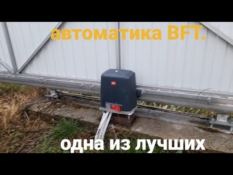
АВТОМАТИКА ДЛЯ ОТКАТНЫХ ВОРОТ BFT 600See more
Автоматика для ворот Home Gate Ltm800 — а стоит ли ?See more

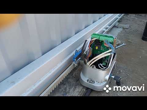
Подключение автоматики для откатных ворот Home gate LT600AC и её работа.See more
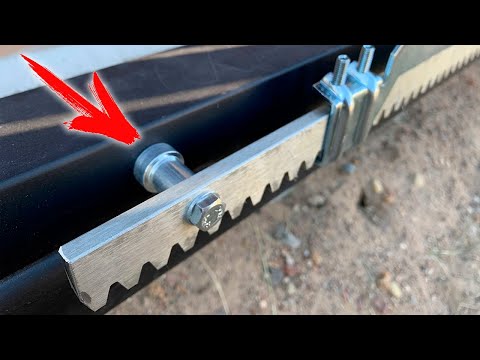
Как установить электропривод для откатных ворот! Монтаж рейки без сварки!See more
🔥 НЕ ПЕРЕПЛАЧИВАЙ! Устанавливаем Автоматику для Откатных Ворот Своими РукамиSee more
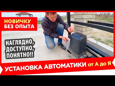
УСТАНОВКА АВТОМАТИКИ ДЛЯ ОТКАТНЫХ ВОРОТ ПОШАГОВАЯ ИНСТРУКЦИЯSee more

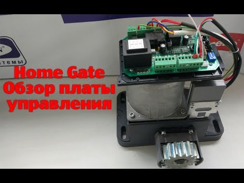
Автоматика Home Gate. Обзор платы управления.See more
Автоматика для откатных ворот (привод) – как выбрать надежную модельSee more
News

Сезонные скидки!!!
Позвоните либо оставьте заявку и мы расскажем Вам об условиях покупки товара с максимально выгодной ценой!
![]() Позвонить
Позвонить
Online-заявка
Производитель FURNITEH (Китай)
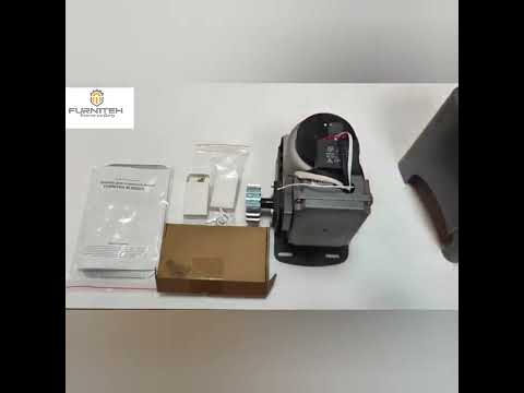
Комплектность:
- Электродвигатель FURNITEH SL 600 AC
- два пульта дистанционного управления
- 2 ключа разблокировки
- монтажная пластина
- комплект магнитов
- монтажный крепеж
Доставка
- Доставка по г.Минск
- Доставка по РБ
Сопутствующие услуги
- Ремонт автоматики ворот
- Сервисное обслуживание ворот
Автоматика для откатных ворот FURNITEH SL 600 AC предназначена для ворот весом до 600 кг. Привод оснащен магнитными концевыми выключателями, обладает само блокирующимся редуктором, блоком управления и встроенным радиоприемником. Данный привод подходит к большинству ворот частного и домашнего использования. Многофункциональная плата позволит легко и быстро подключить любые дополнительные аксессуары, а так же настроить работу привода как вам понравится.
С помощью шести DIP переключателей вы сможете включить/выключить функцию плавного пуска и остановки ворот, автоматического закрытия ворот и автореверса. Четыре переключателя настройки потенциометра позволят настроить резкость остановки, тормозное усилие, диапазона медленного пуска/остановки и настроить крутящий момент.
Внутренняя металлическая шестерня привода FURNITEH SL 600 AC.
Основные преимущества модели:
- Простота настройки и установки.
- Инструкция на русском языке.
- В базовую комплектацию входит все необходимое для установки.
- Металлическая шестерня редуктора.
- Функция замедления.
- Функция частичного открытия.
- В комплекте два пульта д/у.
| Сетевое питание | 220В |
| Напряжение двигателя | 220В |
| Мощность | 280Вт |
| Модуль зубчатого колеса | 4мм (15 зубьев) |
| Скорость на холостом ходу м/мин | 12 |
| Максимальный вес створки | 600кг |
| Реакция на удар | Электронный ограничитель момента |
| Смазка | На весь срок службы |
| Ручное управление | Механическое разблокирование рычагом |
| Тип эксплуатации | Интенсивность 30% |
| Класс защиты |
IP44 |
| Диапазон рабочих температур | от -20 до +70 °C. |
Информация о доставке

Внимание! Возможна быстрая и недорогая доставка по Минску, а также доставка с Минска в Брест, Витебск, Гродно, Гомель и Могилев.
Тажет осуществляем доставку в другие регионы Республики Беларусь. Подробную информацию о возможности доставки уточняйте у наших менеджеров.
Узнать про доставку

500 бел. руб/комплект
455 бел. руб/комплект

825
800 бел. руб/комплект


1248
1040 бел.руб за комплект

824
740 бел. руб/комплект

1190
1085 бел. руб/комплект


825
890 бел.руб/ комплект

775
750 бел. руб/комплект

850
760 бел. руб/комплект
Комплект электропривода для откатных ворот FURNITEH SL 600 AC KIT
Электропривод FURNITEH SL 600 AC предназначен для автоматизации бытовых откатных ворот весом до 600 кг, оснащен магнитными концевыми выключателями. Модель обладает базовым функционалом: настройка усилия двигателя, настройка времени работы, автоматическое закрытие, режим «калитка».
Автоматику FURNITEH SL 600 AC можно рекомендовать к установке на откатные бытовые ворота с обычным (неинтенсивным) режимом использования. Запас мощности и магнитные концевые выключатели позволяют приводу уверенно работать в зимних условиях.
Привод поставляется в комплекте, включающем все необходимое для работы автоматических ворот: привод, 2 пульта, плата управления.
Комплект поставки автоматики для откатных ворот FURNITEH SL600 AC KIT:
 |
Привод FURNITEH SL 600 AC для откатных ворот весом до 600 кг. Электродвигатель 230V AC |
 |
Привод FURNITEH SL600 AC оснащен редуктором с металлической шестерней. |
 |
Привод FURNITEH SL600 AC оснащен бесконтактными магнитными концевыми выключателями. |
 |
2 пульта дистанционного управления FURNITEH. Уже записаны в память привода! |
 |
Электронная плата управления. Встроенный радиоприемник с памятью до 25 пультов ДУ. |
 |
Монтажный набор: метизы, магниты концевых выключателей. |
 |
2 ключа системы разблокировки привода FURNITEH SL 600 AC для перевода ворот в режим ручного передвижения. |
| Инструкция на русском языке по установке, подключению и настройке автоматики для откатных ворот FURNITEH SL 600 AC |