
-
Страница 1
1 ® Strata 128 Strata 128 Strata 128 Strata 128 Strata 128 Strata 128 Plus Strata 128 Plus Strata 128 Plus Strata 128 Plus Strata 128 Plus Strata 128 Por Strata 128 Por Strata 128 Por Strata 128 Por Strata 128 Por table table table table table StrataV StrataV StrataV StrataV StrataV iew iew iew iew iew INST INST INST INST INST ALLA ALLA ALLA ALLA […]
-
Страница 2
2 Eagle Electronics PO Box 669 Catoosa, OK 74015 TABLE OF CONTENTS TABLE OF CONTENTS TABLE OF CONTENTS TABLE OF CONTENTS TABLE OF CONTENTS INTRODUCTION …………………………………………………………………………………. 3 SPECIFICATIONS …………………………………………………………………………..[…]
-
Страница 3
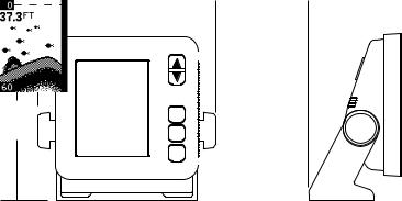
3 SPECIFICATIONS Dimensions …………………. 5.9″ W x 5.35″ H x 3.4″ D Input Voltage ……………….. 10 — 15 vDC Current Drain ………………. 350 ma (lights off) ……………………… 500 ma (lights on) Transmitter Frequency ………. 192 kHz Output Power ….. 275 watts (peak-to-peak) (typical) ……………[…]
-
Страница 4
4 Transducer Installation The transducer included with your sonar is a transom mount transducer The “kick-up” mounting bracket helps prevent damage if the transducer strikes an object while the boat is moving. If the transducer does “kick- up”, the bracket can easily be pushed back in place without tools. Read this manual carefully before a[…]
-
Страница 5
5 Shoot-thru-hull v.s. Transom Mounting (Strata 128 and Strata 128 Plus Only) Typically, shoot-thru-hull installations give excellent high speed opera- tion and good to excellent depth capability. There is no possibility of damage from floating objects. It can’t be knocked off when docking or loading on the trailer. However, the shoot-thru-hul[…]
-
Страница 6
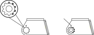
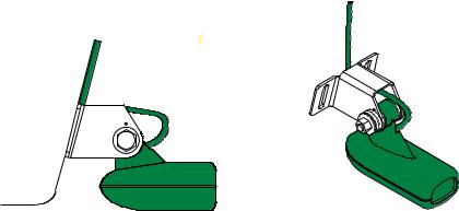
6 2. Slide the tr ansducer between the two ratchets . T emporally slide the bolt though the transducer assemb ly and hold it against the transom. Looking at the transducer from the side , check to see if it will adjust so that its f ace is parallel to the g round. If it does, then the “A” position is correct f or y our hull. If the transducer?[…]
-
Страница 7
7 CAUTION! CAUTION! CAUTION! CAUTION! CAUTION! CLAMP THE TRANSDUCER CABLE TO CLAMP THE TRANSDUCER CABLE TO CLAMP THE TRANSDUCER CABLE TO CLAMP THE TRANSDUCER CABLE TO CLAMP THE TRANSDUCER CABLE TO TRANSOM NEAR THE TRANSDUCER. THIS TRANSOM NEAR THE TRANSDUCER. THIS TRANSOM NEAR THE TRANSDUCER. THIS TRANSOM NEAR THE TRANSDUCER. THIS TRANSOM NEAR THE […]
-
Страница 8
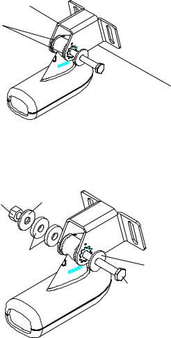
8 5. Remo ve the tr ansducer from the brack et and re-assemb le it with the cable passing through the br ack et ov er the bolt as shown abo v e. At- tach the transducer to the tr ansom. Slide the transducer up or down until it’ s aligned properly on the transom as shown abov e. Tighten the brac ket’ s mounting screws . Adjust the transducer so […]
-
Страница 9
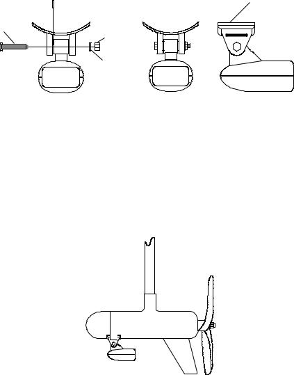
9 NUT FLAT WASHER BOLT 2. Slide the adjustable strap supplied with the TMB-S through the slot in the transducer bracket and wrap it around the trolling motor. Position the transducer to aim straight down when the motor is in the water. Tighten the strap securely. Route the transducer cable alongside the trolling motor shaft. Use plastic ties (not i[…]
-
Страница 10
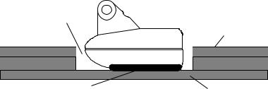
10 SHOOT-THRU-HULL (Strata 128 and Strata 128 Plus Only) The transducer installation inside a fiberglass hull must be in an area that does not have air bubbles in the resin or separated fiberglass layers. The sonar signal must pass through solid fiberglass. A success- ful transducer installation can be made on hulls with flotation materials (such a[…]
-
Страница 11
11 TRANSDUCER LOCATION (HIGH SPEED) TRANSDUCER LOCATION (TROLLING SPEED) 2. Follow the instructions on the epoxy package and mix it thoroughly. Do not mix it too fast, as it will cause bubbles to form in the epoxy. (NOTE! Use only the epoxies specified on the inside front cover of this manual! Failure to use one of these epoxies may result in poor […]
-
Страница 12
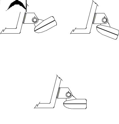
12 TRANSDUCER AIMED TOO TRANSDUCER AIMED TOO TRANSDUCER AIMED TOO TRANSDUCER AIMED TOO TRANSDUCER AIMED TOO FAR FORWARD FAR FORWARD FAR FORWARD FAR FORWARD FAR FORWARD hull. Place the transducer into the epoxy, twisting and turning it to force any air bubbles out from under the transducer face. The face of the transducer should be parallel with the[…]
-
Страница 13
13 3 amp FUSE 12 VOLT BATTERY BLACK WIRE RED WIRE TO SPEED/TEMP SENSOR (STRATA 128 PLUS & STRATAVIEW ONLY) POWER CONNECTIONS — Permanent mount units only This unit works from a 12 volt DC system only. For the best results, run the power cable directly to the boat’s battery. Keep the power cable away from other boat wiring, especially the engi[…]
-
Страница 14
14 Bracket Installation — Permanent mount units only You can install the sonar unit on the top of a dash or from an overhead with the supplied bracket. It can also be installed in the dash with an optional IDA-3 mounting kit. If you use the supplied bracket, you may be interested in the optional GBSA-1 swivel bracket kit. This converts the unit&apo[…]
-
Страница 15
15 STRATA 128 PORTABLE ASSEMBLY INSTALLING THE BATTERIES INSTALLING THE BATTERIES INSTALLING THE BATTERIES INSTALLING THE BATTERIES INSTALLING THE BATTERIES Release the latch on the front of the battery case. Open the compartment and install four «D» cell batteries into the adapter. For the longest life, we recommend you use alkaline batt[…]
-
Страница 16
16 WASHER WASHER NUT BOLT TIE NYLON CORD HERE SCREW PORTABLE TRANSDUCER ASSEMBLY PORTABLE TRANSDUCER ASSEMBLY PORTABLE TRANSDUCER ASSEMBLY PORTABLE TRANSDUCER ASSEMBLY PORTABLE TRANSDUCER ASSEMBLY Assemble the transducer and bracket as shown below. Attach the transducer to the bracket with the supplied hardware. Make certain there is one washer on […]
-
Страница 17
17 Clean the chosen area of the hull before attaching the suction cup. Locate the transducer on the hull as shown below. Don’t allow the bracket to go below the hull, as water pressure against it can cause the suction cup to come off at speed. Moisten the cup, then press it onto the hull as firmly as possible. Tie the nylon cord to the boat an[…]
-
Страница 18
18 Sensor Chart (Note: Do not use these sensors in any other combination.) ST-TBK = 1 speed sensor and 1 temperature display ST-T BK + TS-2BK = 2 temp sensors and one speed sensor ST-TBK + TS-2BK + TS-3BK = 3 temp sensors and one speed sensor TS-1BK = 1 temperature sensor TS-12BK = 2 temperature sensors or TS-1BK + TS-2BK = 2 temperature sensors TS[…]
-
Страница 19
19 Three Temperature Sensors (Water, T-2, and T-3) Three Temperature Sensors plus Speed (Water, T-2, T-3, and Speed) TS-12 BK TS-3 BK ST-TBK TS-2 BK TS-3 BK STRATA PLUS OR STRATAVIEW POWER CABLE Sensor Chart (Note: Do not use these sensors in any other combina- tion.) STRATA PLUS OR STRATAVIEW POWER CABLE[…]
-
Страница 20
20 KEYBOARD BASICS The unit sounds a tone when you press any key. This tells you the unit has ac- cepted a command. PWR/CLEAR Use this key to turn the unit on. It also clears menu selections and the menus from the screen. This key also turns the unit off. NOTE: You must hold the OFF key down for a few seconds in order to turn the unit OFF. MENU FWD[…]
-
Страница 21
21 OPERATION MENUS This unit uses menus to guide you through the unit’s functions and features. The menu key accesses these features, allowing you to cus- tomize the unit to your particular needs and water conditions. All you have to do to leave one menu and enter another is press the menu key repeatedly. If you ever get lost in the menus, simply[…]
-
Страница 22
22 After you select the desired range, press the PWR key to clear the display. If you wait a few seconds, it will automatically clear. This unit has the following ranges: 10, 20, 40, 60, 120, 240, 480, and 900 feet. and 5, 10, 20, 40, 60, 100, 200, and 300 meters. ZOOM The zoom feature enlarges all echoes on the screen. If the unit is in the automa[…]
-
Страница 23
23 This means the unit is tracking the bottom in a zoom window, always keeping it on the display. Press the up arrow key to decrease the zoom size, press the down arrow key to increase the zoom size. When the unit is switched into the zoom mode, the letters “ZM” appear at the top of the screen. The zoom window size displays in the top right cor[…]
-
Страница 24
24 SENSITIVITY The sensitivity menu lets you control the unit’s ability to pick up echoes. A low sensitivity level excludes much of the bottom information, fish signals, and other detail. High sensitivity settings lets you see features, but it can also clutter the screen with noise and other unwanted signals. Typically, the best sensitivity level[…]
-
Страница 25
25 Grayline ® is adjustable. Since it shows the difference between strong and weak echoes, changing the level may require a different sensitivity setting. To change the Grayline level, first press the MENU key until the Grayline menu appears. Now press the up arrow key to increase the level, the down arrow to decrease it. The percentage of Graylin[…]
-
Страница 26
26 The Fish ID feature can’t be used when the unit is in the manual mode. If you turn the automatic feature off, the Fish ID feature will automatically be turned off, also. FISH TRACK™ This unit automatically displays the depth of a target when the Fish ID feature places a fish symbol on the screen as shown below. This feature is automatically […]
-
Страница 27
27 CHART SPEED The rate echoes scroll across the screen is called the chart speed. It’s adjustable by pressing the menu key until the chart speed menu appears. Chart speed is set to maxi- mum when the unit is first turned on. To decrease it, press the down arrow key. Press the up arrow key to increase the speed again. The percent numbers in the C[…]
-
Страница 28
28 DISPLAY MODE The Strata 128 has three different screen modes. The Strata 128 Plus and Strataview both have eight modes. To change modes, press the MENU key until the “DISP MODE” (Display Mode) menu appears. Then press the up or down arrow keys until the desired mode number appears. The modes are as follows: STRATA 128 and STRATA 128 Portable[…]
-
Страница 29
29 STRATA 128 PLUS and STRATAVIEW ONLY CHT 1 (Chart #1) This is the default mode used when the unit is first turned on. It has the following features: 1. Automatic On 2. Fish ID Feature On 3. Digital Depth Display On CHT 2 (Chart #2) Same as Chart-1, but with water tempera- ture added. CHT 3 (Chart #3) Same as Chart-1, but with speed added.[…]
-
Страница 30
30 STRATA 128 PLUS and STRATAVIEW ONLY (cont.) CHT 4 (Chart #4) Same as Chart-1, but with water tempera- ture and speed added. CHT 5 (Chart #5) This is the High Speed Scroll mode. It shifts the chart speed into high gear, scrolling ech- oes at a high rate. It has the following fea- tures: 1. Automatic Off 2. Fish ID Feature Off 3. Digital Depth Dis[…]
-
Страница 31
31 STRATA 128 PLUS and STRATAVIEW ONLY (cont.) DIG 2 (Digital #2) Digital depth, water temperature, speed, and distance log (odometer) show on this page. To reset the log, turn the unit off and back on again. DIG 3 (Digital #3) Digital depth, water temperature, T-2 tem- perature, and T-3 temperature all show on this screen. Temperature Probe Select[…]
-
Страница 32
32 ALARMS FISH ALARM The Fish Alarm sounds a tone when a fish symbol appears on the screen. To use the fish alarm, press the menu key until the “FISH ALARM” menu appears on the screen. Now press the up arrow key to turn the alarm on. Repeat the above steps to turn the fish alarm off. DEPTH ALARMS The depth alarms are triggered only by the botto[…]
-
Страница 33
33 Deep Alarm The deep alarm adjusts the same as the shallow alarm. Use the “DEEP ALARM” menu to adjust the deep alarm. When the bottom signal goes deeper than the setting, an alarm tone sounds. LIGHTS The display is backlighted for night use. To turn the backlights on or off, press the menu key repeatedly until the BACK LIGHT menu appears. Now[…]
-
Страница 34
34 shows a graph of the contrast. The screen will also show the effects of the change. If you reach the maximum or minimum level, a tone sounds alerting you to the limits. The menu will clear automatically after a few seconds or you can press the PWR key to clear the screen. ASP (Advanced Signal Processing) ASP is a program embedded in the computer[…]
-
Страница 35
35 TROUBLESHOOTING — IMPORTANT INFORMATION! If your unit is not working, or if you need technical help, please use the following troubleshooting section before contacting the factory customer service department. It may save you the trouble of returning your unit. Unit freezes, locks up, or operates erratically: 1. Electrical noise from the boat’s[…]
-
Страница 36
36 the digital will flash continuously. It may change the range to limits far greater than the water you are in. If this happens, place the unit in the manual mode, then change the range to a realistic one, (for example, 0- 100 feet) and increase the sensitivity. As you move into shallower water, a bottom signal should appear. 4. Check the battery […]
-
Страница 37
37 ELECTRICAL NOISE A major cause of sonar problems is electrical noise. This usually appears on the sonar’s display as random patterns of dots or lines. In severe cases, it can completely cover the screen with black dots, or cause the unit operate erratically, or not at all. To eliminate or minimize the effects of electrical noise, first try to […]
-
Страница 38
38 EAGLE ELECTRONICS FULL ONE-YEAR WARRANTY “We», “our”, or “us” refers to EAGLE ELECTRONICS, a division of LEI, the manufacturer of this product. “You” or “your” refers to the first person who purchases this product as a consumer item for personal, family, or household use. We warrant this product against defects or malfunct[…]
-
Страница 39
39 Ho w to Obtain Ser vice (Canadian Customers Only) We back your investment in quality products with quick, expert service and genuine Eagle replacement parts. If you need service or repairs, contact the Eagle Factory Customer Service Department at the toll-free number listed below. A technician may be able to solve the problem and save you the in[…]
-
Страница 40
40 LITHO IN U.S.A. 988-0143-34 EAGLE ELECTRONICS PO BOX 669 CATOOSA OK 74015 Your unit is covered by a full one-year warranty. (See inside for complete warranty details.) If your unit fails and the failure is not covered by the original warranty, Eagle has a flat-rate repair policy that covers your unit and accessories packed with the unit at the f[…]
-
Page 1: Eagle STRATA 128
1 ® Strata 128 Strata 128 Strata 128 Strata 128 Strata 128 Strata 128 Plus Strata 128 Plus Strata 128 Plus Strata 128 Plus Strata 128 Plus Strata 128 Por Strata 128 Por Strata 128 Por Strata 128 Por Strata 128 Por table table table table table StrataV StrataV StrataV StrataV StrataV iew iew iew iew iew INST INST INST INST INST ALLA ALLA ALLA ALLA […]
-
Page 2: Eagle STRATA 128
2 Eagle Electronics PO Box 669 Catoosa, OK 74015 TABLE OF CONTENTS TABLE OF CONTENTS TABLE OF CONTENTS TABLE OF CONTENTS TABLE OF CONTENTS INTRODUCTION …………………………………………………………………………………. 3 SPECIFICATIONS …………………………………………………………………………..[…]
-
Page 3: Eagle STRATA 128
3 SPECIFICATIONS Dimensions …………………. 5.9″ W x 5.35″ H x 3.4″ D Input Voltage ……………….. 10 — 15 vDC Current Drain ………………. 350 ma (lights off) ……………………… 500 ma (lights on) Transmitter Frequency ………. 192 kHz Output Power ….. 275 watts (peak-to-peak) (typical) ……………[…]
-
Page 4: Eagle STRATA 128
4 Transducer Installation The transducer included with your sonar is a transom mount transducer The “kick-up” mounting bracket helps prevent damage if the transducer strikes an object while the boat is moving. If the transducer does “kick- up”, the bracket can easily be pushed back in place without tools. Read this manual carefully before a[…]
-
Page 5: Eagle STRATA 128
5 Shoot-thru-hull v.s. Transom Mounting (Strata 128 and Strata 128 Plus Only) Typically, shoot-thru-hull installations give excellent high speed opera- tion and good to excellent depth capability. There is no possibility of damage from floating objects. It can’t be knocked off when docking or loading on the trailer. However, the shoot-thru-hul[…]
-
Page 6: Eagle STRATA 128
6 2. Slide the tr ansducer between the two ratchets . T emporally slide the bolt though the transducer assemb ly and hold it against the transom. Looking at the transducer from the side , check to see if it will adjust so that its f ace is parallel to the g round. If it does, then the “A” position is correct f or y our hull. If the transducer?[…]
-
Page 7: Eagle STRATA 128
7 CAUTION! CAUTION! CAUTION! CAUTION! CAUTION! CLAMP THE TRANSDUCER CABLE TO CLAMP THE TRANSDUCER CABLE TO CLAMP THE TRANSDUCER CABLE TO CLAMP THE TRANSDUCER CABLE TO CLAMP THE TRANSDUCER CABLE TO TRANSOM NEAR THE TRANSDUCER. THIS TRANSOM NEAR THE TRANSDUCER. THIS TRANSOM NEAR THE TRANSDUCER. THIS TRANSOM NEAR THE TRANSDUCER. THIS TRANSOM NEAR THE […]
-
Page 8: Eagle STRATA 128
8 5. Remo ve the tr ansducer from the brack et and re-assemb le it with the cable passing through the br ack et ov er the bolt as shown abo v e. At- tach the transducer to the tr ansom. Slide the transducer up or down until it’ s aligned properly on the transom as shown abov e. Tighten the brac ket’ s mounting screws . Adjust the transducer so […]
-
Page 9: Eagle STRATA 128
9 NUT FLAT WASHER BOLT 2. Slide the adjustable strap supplied with the TMB-S through the slot in the transducer bracket and wrap it around the trolling motor. Position the transducer to aim straight down when the motor is in the water. Tighten the strap securely. Route the transducer cable alongside the trolling motor shaft. Use plastic ties (not i[…]
-
Page 10: Eagle STRATA 128
10 SHOOT-THRU-HULL (Strata 128 and Strata 128 Plus Only) The transducer installation inside a fiberglass hull must be in an area that does not have air bubbles in the resin or separated fiberglass layers. The sonar signal must pass through solid fiberglass. A success- ful transducer installation can be made on hulls with flotation materials (such a[…]
-
Page 11: Eagle STRATA 128
11 TRANSDUCER LOCATION (HIGH SPEED) TRANSDUCER LOCATION (TROLLING SPEED) 2. Follow the instructions on the epoxy package and mix it thoroughly. Do not mix it too fast, as it will cause bubbles to form in the epoxy. (NOTE! Use only the epoxies specified on the inside front cover of this manual! Failure to use one of these epoxies may result in poor […]
-
Page 12: Eagle STRATA 128
12 TRANSDUCER AIMED TOO TRANSDUCER AIMED TOO TRANSDUCER AIMED TOO TRANSDUCER AIMED TOO TRANSDUCER AIMED TOO FAR FORWARD FAR FORWARD FAR FORWARD FAR FORWARD FAR FORWARD hull. Place the transducer into the epoxy, twisting and turning it to force any air bubbles out from under the transducer face. The face of the transducer should be parallel with the[…]
-
Page 13: Eagle STRATA 128
13 3 amp FUSE 12 VOLT BATTERY BLACK WIRE RED WIRE TO SPEED/TEMP SENSOR (STRATA 128 PLUS & STRATAVIEW ONLY) POWER CONNECTIONS — Permanent mount units only This unit works from a 12 volt DC system only. For the best results, run the power cable directly to the boat’s battery. Keep the power cable away from other boat wiring, especially the engi[…]
-
Page 14: Eagle STRATA 128
14 Bracket Installation — Permanent mount units only You can install the sonar unit on the top of a dash or from an overhead with the supplied bracket. It can also be installed in the dash with an optional IDA-3 mounting kit. If you use the supplied bracket, you may be interested in the optional GBSA-1 swivel bracket kit. This converts the unit&apo[…]
-
Page 15: Eagle STRATA 128
15 STRATA 128 PORTABLE ASSEMBLY INSTALLING THE BATTERIES INSTALLING THE BATTERIES INSTALLING THE BATTERIES INSTALLING THE BATTERIES INSTALLING THE BATTERIES Release the latch on the front of the battery case. Open the compartment and install four «D» cell batteries into the adapter. For the longest life, we recommend you use alkaline batt[…]
-
Page 16: Eagle STRATA 128
16 WASHER WASHER NUT BOLT TIE NYLON CORD HERE SCREW PORTABLE TRANSDUCER ASSEMBLY PORTABLE TRANSDUCER ASSEMBLY PORTABLE TRANSDUCER ASSEMBLY PORTABLE TRANSDUCER ASSEMBLY PORTABLE TRANSDUCER ASSEMBLY Assemble the transducer and bracket as shown below. Attach the transducer to the bracket with the supplied hardware. Make certain there is one washer on […]
-
Page 17: Eagle STRATA 128
17 Clean the chosen area of the hull before attaching the suction cup. Locate the transducer on the hull as shown below. Don’t allow the bracket to go below the hull, as water pressure against it can cause the suction cup to come off at speed. Moisten the cup, then press it onto the hull as firmly as possible. Tie the nylon cord to the boat an[…]
-
Page 18: Eagle STRATA 128
18 Sensor Chart (Note: Do not use these sensors in any other combination.) ST-TBK = 1 speed sensor and 1 temperature display ST-T BK + TS-2BK = 2 temp sensors and one speed sensor ST-TBK + TS-2BK + TS-3BK = 3 temp sensors and one speed sensor TS-1BK = 1 temperature sensor TS-12BK = 2 temperature sensors or TS-1BK + TS-2BK = 2 temperature sensors TS[…]
-
Page 19: Eagle STRATA 128
19 Three Temperature Sensors (Water, T-2, and T-3) Three Temperature Sensors plus Speed (Water, T-2, T-3, and Speed) TS-12 BK TS-3 BK ST-TBK TS-2 BK TS-3 BK STRATA PLUS OR STRATAVIEW POWER CABLE Sensor Chart (Note: Do not use these sensors in any other combina- tion.) STRATA PLUS OR STRATAVIEW POWER CABLE[…]
-
Page 20: Eagle STRATA 128
20 KEYBOARD BASICS The unit sounds a tone when you press any key. This tells you the unit has ac- cepted a command. PWR/CLEAR Use this key to turn the unit on. It also clears menu selections and the menus from the screen. This key also turns the unit off. NOTE: You must hold the OFF key down for a few seconds in order to turn the unit OFF. MENU FWD[…]
-
Page 21: Eagle STRATA 128
21 OPERATION MENUS This unit uses menus to guide you through the unit’s functions and features. The menu key accesses these features, allowing you to cus- tomize the unit to your particular needs and water conditions. All you have to do to leave one menu and enter another is press the menu key repeatedly. If you ever get lost in the menus, simply[…]
-
Page 22: Eagle STRATA 128
22 After you select the desired range, press the PWR key to clear the display. If you wait a few seconds, it will automatically clear. This unit has the following ranges: 10, 20, 40, 60, 120, 240, 480, and 900 feet. and 5, 10, 20, 40, 60, 100, 200, and 300 meters. ZOOM The zoom feature enlarges all echoes on the screen. If the unit is in the automa[…]
-
Page 23: Eagle STRATA 128
23 This means the unit is tracking the bottom in a zoom window, always keeping it on the display. Press the up arrow key to decrease the zoom size, press the down arrow key to increase the zoom size. When the unit is switched into the zoom mode, the letters “ZM” appear at the top of the screen. The zoom window size displays in the top right cor[…]
-
Page 24: Eagle STRATA 128
24 SENSITIVITY The sensitivity menu lets you control the unit’s ability to pick up echoes. A low sensitivity level excludes much of the bottom information, fish signals, and other detail. High sensitivity settings lets you see features, but it can also clutter the screen with noise and other unwanted signals. Typically, the best sensitivity level[…]
-
Page 25: Eagle STRATA 128
25 Grayline ® is adjustable. Since it shows the difference between strong and weak echoes, changing the level may require a different sensitivity setting. To change the Grayline level, first press the MENU key until the Grayline menu appears. Now press the up arrow key to increase the level, the down arrow to decrease it. The percentage of Graylin[…]
-
Page 26: Eagle STRATA 128
26 The Fish ID feature can’t be used when the unit is in the manual mode. If you turn the automatic feature off, the Fish ID feature will automatically be turned off, also. FISH TRACK™ This unit automatically displays the depth of a target when the Fish ID feature places a fish symbol on the screen as shown below. This feature is automatically […]
-
Page 27: Eagle STRATA 128
27 CHART SPEED The rate echoes scroll across the screen is called the chart speed. It’s adjustable by pressing the menu key until the chart speed menu appears. Chart speed is set to maxi- mum when the unit is first turned on. To decrease it, press the down arrow key. Press the up arrow key to increase the speed again. The percent numbers in the C[…]
-
Page 28: Eagle STRATA 128
28 DISPLAY MODE The Strata 128 has three different screen modes. The Strata 128 Plus and Strataview both have eight modes. To change modes, press the MENU key until the “DISP MODE” (Display Mode) menu appears. Then press the up or down arrow keys until the desired mode number appears. The modes are as follows: STRATA 128 and STRATA 128 Portable[…]
-
Page 29: Eagle STRATA 128
29 STRATA 128 PLUS and STRATAVIEW ONLY CHT 1 (Chart #1) This is the default mode used when the unit is first turned on. It has the following features: 1. Automatic On 2. Fish ID Feature On 3. Digital Depth Display On CHT 2 (Chart #2) Same as Chart-1, but with water tempera- ture added. CHT 3 (Chart #3) Same as Chart-1, but with speed added.[…]
-
Page 30: Eagle STRATA 128
30 STRATA 128 PLUS and STRATAVIEW ONLY (cont.) CHT 4 (Chart #4) Same as Chart-1, but with water tempera- ture and speed added. CHT 5 (Chart #5) This is the High Speed Scroll mode. It shifts the chart speed into high gear, scrolling ech- oes at a high rate. It has the following fea- tures: 1. Automatic Off 2. Fish ID Feature Off 3. Digital Depth Dis[…]
-
Page 31: Eagle STRATA 128
31 STRATA 128 PLUS and STRATAVIEW ONLY (cont.) DIG 2 (Digital #2) Digital depth, water temperature, speed, and distance log (odometer) show on this page. To reset the log, turn the unit off and back on again. DIG 3 (Digital #3) Digital depth, water temperature, T-2 tem- perature, and T-3 temperature all show on this screen. Temperature Probe Select[…]
-
Page 32: Eagle STRATA 128
32 ALARMS FISH ALARM The Fish Alarm sounds a tone when a fish symbol appears on the screen. To use the fish alarm, press the menu key until the “FISH ALARM” menu appears on the screen. Now press the up arrow key to turn the alarm on. Repeat the above steps to turn the fish alarm off. DEPTH ALARMS The depth alarms are triggered only by the botto[…]
-
Page 33: Eagle STRATA 128
33 Deep Alarm The deep alarm adjusts the same as the shallow alarm. Use the “DEEP ALARM” menu to adjust the deep alarm. When the bottom signal goes deeper than the setting, an alarm tone sounds. LIGHTS The display is backlighted for night use. To turn the backlights on or off, press the menu key repeatedly until the BACK LIGHT menu appears. Now[…]
-
Page 34: Eagle STRATA 128
34 shows a graph of the contrast. The screen will also show the effects of the change. If you reach the maximum or minimum level, a tone sounds alerting you to the limits. The menu will clear automatically after a few seconds or you can press the PWR key to clear the screen. ASP (Advanced Signal Processing) ASP is a program embedded in the computer[…]
-
Page 35: Eagle STRATA 128
35 TROUBLESHOOTING — IMPORTANT INFORMATION! If your unit is not working, or if you need technical help, please use the following troubleshooting section before contacting the factory customer service department. It may save you the trouble of returning your unit. Unit freezes, locks up, or operates erratically: 1. Electrical noise from the boat’s[…]
-
Page 36: Eagle STRATA 128
36 the digital will flash continuously. It may change the range to limits far greater than the water you are in. If this happens, place the unit in the manual mode, then change the range to a realistic one, (for example, 0- 100 feet) and increase the sensitivity. As you move into shallower water, a bottom signal should appear. 4. Check the battery […]
-
Page 37: Eagle STRATA 128
37 ELECTRICAL NOISE A major cause of sonar problems is electrical noise. This usually appears on the sonar’s display as random patterns of dots or lines. In severe cases, it can completely cover the screen with black dots, or cause the unit operate erratically, or not at all. To eliminate or minimize the effects of electrical noise, first try to […]
-
Page 38: Eagle STRATA 128
38 EAGLE ELECTRONICS FULL ONE-YEAR WARRANTY “We», “our”, or “us” refers to EAGLE ELECTRONICS, a division of LEI, the manufacturer of this product. “You” or “your” refers to the first person who purchases this product as a consumer item for personal, family, or household use. We warrant this product against defects or malfunct[…]
-
Page 39: Eagle STRATA 128
39 Ho w to Obtain Ser vice (Canadian Customers Only) We back your investment in quality products with quick, expert service and genuine Eagle replacement parts. If you need service or repairs, contact the Eagle Factory Customer Service Department at the toll-free number listed below. A technician may be able to solve the problem and save you the in[…]
-
Page 40: Eagle STRATA 128
40 LITHO IN U.S.A. 988-0143-34 EAGLE ELECTRONICS PO BOX 669 CATOOSA OK 74015 Your unit is covered by a full one-year warranty. (See inside for complete warranty details.) If your unit fails and the failure is not covered by the original warranty, Eagle has a flat-rate repair policy that covers your unit and accessories packed with the unit at the f[…]
- Инструкции и руководства
- Бренды
- Eagle Electronics
- 128
- Справочник Пользователя
1
®
Strata 128
Strata 128
Strata 128
Strata 128
Strata 128
Strata 128 Plus
Strata 128 Plus
Strata 128 Plus
Strata 128 Plus
Strata 128 Plus
Strata 128 Por
Strata 128 Por
Strata 128 Por
Strata 128 Por
Strata 128 Portable
table
table
table
table
StrataV
StrataV
StrataV
StrataV
StrataView
iew
iew
iew
iew
INST
INST
INST
INST
INSTALLA
ALLA
ALLA
ALLA
ALLATION AND OPERA
TION AND OPERA
TION AND OPERA
TION AND OPERA
TION AND OPERATION
TION
TION
TION
TION
INSTR
INSTR
INSTR
INSTR
INSTRUCTIONS
UCTIONS
UCTIONS
UCTIONS
UCTIONS
Руководстве по эксплуатации Eagle STRATA 128 — вам приходилось его терять? Поскольку вы попали сюда, наверняка с вами это случилось. Но вы не единственный человек, сталкивающийся с проблемами с хранением руководства по эксплуатации всех домашних устройств. Ниже несколько советов, касающихся того, зачем собирать руководства по эксплуатации.
Руководстве по эксплуатации Eagle STRATA 128 это определенный вид технической документации, являющейся неразлучным элементом каждого устройства, которое мы приобретаем. Они отличаются между собой количеством информации, которую можно найти на тему данного устройства: напр. Eagle STRATA 128. Конечно же, если производитель считает что необходимо передать нам большее количество информации, касающейся устройства Eagle STRATA 128, то стоит ее хоть раз прочитать — в начале, сразу же после покупки данной вещи. Однако мы считаем, что инструкции должны заключать самую важную, наиболее необходимую информацию о Eagle STRATA 128, так, чтобы не отнимать желания пользователя прочесть ее уже в самом начале. Несомненно, если устройство Eagle STRATA 128 имеет много продвинутых функций, неизбежно большое количество информации в содержании этого документа.
Które из информации в инструкции Eagle STRATA 128 необходимо обязательно прочитать?
- Информацию, касающуюся правильного использования и ухода за устройством Eagle STRATA 128 — нам необходимо ознакомиться с основными правилами, чтобы в случае проблем с устройством сервисный центр не отказал нам в гарантийном обслуживании, из-за неправильного использования
- Информация, касающаяся самых частых проблем с Eagle STRATA 128 и способы их решения
- Информация, касающаяся гарантии устройства Eagle STRATA 128 и ближайших сервисных центров, способных починить устройство в соответствии с рекомендациям производителя Eagle
Как хранить инструкции дома?
Хорошей идеей является предназначение одного ящика, в котором бы хранилась инструкция Eagle STRATA 128 а также всех других домашних устройств которыми мы пользуемся. Тогда значительно легче вам будет ее найти, чем искать в родных коробках, которые наверняка уже выбросили вы, или другие домочадцы. Раз в год достаточно просмотреть ящик и выбросить инструкции, которые касаются устройств, которыми вы уже не пользуетесь. Таким образом вы избежите хранения ненужных документов, а останутся только актуальные. Вы можете также скачать и распечатать инструкцию Eagle STRATA 128 чтобы разместить ее в своем ящике.
Похожие инструкции
Краткое содержание страницы № 1
Strata 128 Strata 128 Strata 128 Strata 128 Strata 128
Strata 128 Plus Strata 128 Plus
Strata 128 Plus Strata 128 Plus Strata 128 Plus
Strata 128 Por Strata 128 Portable table
Strata 128 Por Strata 128 Por Strata 128 Portable table table
StrataV StrataV StrataView iew iew
StrataV StrataView iew
INST INST INSTALLA ALLA ALLATION AND OPERA TION AND OPERA TION AND OPERATION TION TION
INST INSTALLA ALLATION AND OPERA TION AND OPERATION TION
INSTR INSTR INSTR INSTR INSTRUCTIONS UCTIONS UCTIONS UCTIONS
Краткое содержание страницы № 2
TABLE OF CONTENTS TABLE OF CONTENTS TABLE OF CONTENTS TABLE OF CONTENTS TABLE OF CONTENTS INTRODUCTION…………………………………………………………………………………. 3 SPECIFICATIONS ……………………………………………………………………………….3 INSTALLATION -Transducer …………………………………………………………………5 POWER CONNECTIONS ……………………………………………………………….
Краткое содержание страницы № 3
INTRODUCTION Thank you for purchasing an Eagle sonar. Your sonar unit is a high quality sonar designed for both professional and novice fishermen. All of our sonars have an automatic feature that finds and displays the bottom, fish, structure, and more! All you have to do is press the on key. However, if you wish to fine tune the unit, all you have to do is press the menu key. The Strata series has powerful features available through easy-to-use menus. To get started with your Eagle unit, f
Краткое содержание страницы № 4
Transducer Installation The transducer included with your sonar is a transom mount transducer The “kick-up” mounting bracket helps prevent damage if the transducer strikes an object while the boat is moving. If the transducer does “kick- up”, the bracket can easily be pushed back in place without tools. Read this manual carefully before attempting the installation. Determine which of the mounting positions is right for your boat. Use extreme care if mounting the transducer inside the hull, si
Краткое содержание страницы № 5
Shoot-thru-hull v.s. Transom Mounting (Strata 128 and Strata 128 Plus Only) Typically, shoot-thru-hull installations give excellent high speed opera- tion and good to excellent depth capability. There is no possibility of damage from floating objects. It can’t be knocked off when docking or loading on the trailer. However, the shoot-thru-hull installation does have its drawbacks. One, some loss of sensitivity does occur, even on the best hulls. This varies from hull to hull, even from differ
Краткое содержание страницы № 6
2. Slide the transducer between the two ratchets. Temporally slide the bolt though the transducer assembly and hold it against the transom. Looking at the transducer from the side, check to see if it will adjust so that its face is parallel to the ground. If it does, then the “A” position is correct for your hull. If the transducer’s face isn’t parallel with the ground, remove the transducer and ratchets from the bracket. Place the ratch- ets into the holes in the bracket with the letter “B” ali
Краткое содержание страницы № 7
CAUTION! CAUTION! CAUTION! CAUTION! CAUTION! CLAMP THE TRANSDUCER CABLE TO CLAMP THE TRANSDUCER CABLE TO CLAMP THE TRANSDUCER CABLE TO CLAMP THE TRANSDUCER CABLE TO CLAMP THE TRANSDUCER CABLE TO TRANSOM NEAR THE TRANSDUCER. THIS TRANSOM NEAR THE TRANSDUCER. THIS TRANSOM NEAR THE TRANSDUCER. THIS TRANSOM NEAR THE TRANSDUCER. THIS TRANSOM NEAR THE TRANSDUCER. THIS WILL HELP PREVENT THE TRANSDUCER WILL HELP PREVENT THE TRANSDUCER WILL HELP PREVENT THE TRANSDUCER WILL HELP PREVENT THE TRANSDUCE
Краткое содержание страницы № 8
5. Remove the transducer from the bracket and re-assemble it with the cable passing through the bracket over the bolt as shown above. At- tach the transducer to the transom. Slide the transducer up or down until it’s aligned properly on the transom as shown above. Tighten the bracket’s mounting screws. Adjust the transducer so that it’s parallel to the ground and tighten the lock nut until it touches the flat washer, then add 1/4 turn. Don’t over tighten the lock nut! If you do, the transducer w
Краткое содержание страницы № 9
TROLLING MOTOR BRACKET INSTALLATION (StrataView Only) 1. Attach the TMB-S bracket to the transducer as shown below using the hardware supplied with the transducer. (Note: The internal tooth washer is supplied with the TMB-S.) TMB-S INTERNAL TOOTH BRACKET WASHER BOLT NUT FLAT WASHER 2. Slide the adjustable strap supplied with the TMB-S through the slot in the transducer bracket and wrap it around the trolling motor. Position the transducer to aim straight down when the motor is in the water. Tig
Краткое содержание страницы № 10
SHOOT-THRU-HULL (Strata 128 and Strata 128 Plus Only) The transducer installation inside a fiberglass hull must be in an area that does not have air bubbles in the resin or separated fiberglass layers. The sonar signal must pass through solid fiberglass. A success- ful transducer installation can be made on hulls with flotation materials (such as plywood, balsa wood, or foam) between layers of fiberglass if the material is removed from the chosen area. For example, some manufacturers use a la
Краткое содержание страницы № 11
TRANSDUCER LOCATION TRANSDUCER LOCATION (HIGH SPEED) (TROLLING SPEED) Shoot-thru-hull Installation (Strata 128 and Strata 128 Plus Only) 1. Make certain the area is clean, dry, and free of oil or grease, then sand both the inside surface of the hull and the face of the transducer with 100 grit sandpaper. The surface of the hull must be flat so the entire transducer face is in contact with the hull prior to bonding. SPREAD EPOXY HERE SAND THIS SURFACE 2. Follow the instructions on the epoxy p
Краткое содержание страницы № 12
hull. Place the transducer into the epoxy, twisting and turning it to force any air bubbles out from under the transducer face. The face of the transducer should be parallel with the hull, with a minimum amount of epoxy between the hull and transducer. After the epoxy dries, route the cable to the sonar unit. Fish Arches If you do not get good fish arches on your display, it could be the transducer is not parallel with the ground when the boat is at rest in the water, or at slow trolling spee
Краткое содержание страницы № 13
POWER CONNECTIONS — Permanent mount units only This unit works from a 12 volt DC system only. For the best results, run the power cable directly to the boat’s battery. Keep the power cable away from other boat wiring, especially the engine’s wires. This will give the best isolation from electrical noise. If the supplied cable is not long enough to reach the battery, splice #18 gauge insulated wire to it. You can attach the power cable to an accessory or power buss, however, you may have problems
Краткое содержание страницы № 14
Bracket Installation — Permanent mount units only You can install the sonar unit on the top of a dash or from an overhead with the supplied bracket. It can also be installed in the dash with an optional IDA-3 mounting kit. If you use the supplied bracket, you may be interested in the optional GBSA-1 swivel bracket kit. This converts the unit’s gimbal bracket to a swivel mount which can be used on the dash or overhead mounting positions. Installation instructions for the in-dash and swivel mounti
Краткое содержание страницы № 15
STRATA 128 PORTABLE ASSEMBLY INSTALLING THE BATTERIES INSTALLING THE BATTERIES INSTALLING THE BATTERIES INSTALLING THE BATTERIES INSTALLING THE BATTERIES Release the latch on the front of the battery case. Open the compartment and install four «D» cell batteries into the adapter. For the longest life, we recommend you use alkaline batteries. This battery case will also hold one rechargable battery instead of the «D» cells. See the enclosed coupon for more information on the rechargable battery
Краткое содержание страницы № 16
receive about portable units result from stale batteries. Make certain the ones you buy are fresh. Always remove batteries from the battery compartment before storing the unit as dead batteries can leak and corrode the contacts. In cold weather the efficiency of dry cell batteries drops with the tempera- ture. We find it a good idea to have the sonar unit good and warm along with the batteries before we leave home. If the batteries do lose a charge, you can sometimes restore them by placing t
Краткое содержание страницы № 17
Clean the chosen area of the hull before attaching the suction cup. Locate the transducer on the hull as shown below. Don’t allow the bracket to go below the hull, as water pressure against it can cause the suction cup to come off at speed. Moisten the cup, then press it onto the hull as firmly as possible. Tie the nylon cord to the boat and route the transducer cable to the sonar unit. Plug the transducer connector into the unit and your portable sonar is now ready for use. HULL SPEED/TEM
Краткое содержание страницы № 18
Sensor Chart (Note: Do not use these sensors in any other combination.) ST-TBK = 1 speed sensor and 1 temperature display ST-T BK + TS-2BK = 2 temp sensors and one speed sensor ST-TBK + TS-2BK + TS-3BK = 3 temp sensors and one speed sensor TS-1BK = 1 temperature sensor TS-12BK = 2 temperature sensors or TS-1BK + TS-2BK = 2 temperature sensors TS-12BK + TS-3BK = 3 temperature sensors or TS-1BK + TS-2BK +TS-3BK = 3 temperature sensors Here’s some sample wiring diagrams: TS-12 BK Two Temperature Se
Краткое содержание страницы № 19
TS-12 BK Sensor Chart (Note: Do not use these sensors in any other combina- tion.) TS-3 BK Three Temperature Sensors (Water, T-2, and T-3) STRATA PLUS OR STRATAVIEW POWER CABLE ST-TBK TS-2 BK TS-3 BK Three Temperature Sensors plus Speed (Water, T-2, T-3, and Speed) STRATA PLUS OR STRATAVIEW POWER CABLE 19
Краткое содержание страницы № 20
KEYBOARD BASICS The unit sounds a tone when you press any key. This tells you the unit has ac- cepted a command. PWR/CLEAR Use this key to turn the unit on. It also clears menu selections and the menus from the screen. This key also turns the unit off. NOTE: You must hold the OFF key down for a few seconds in order to turn the unit OFF. MENU FWD / MENU REV These sonar units have many features that are accessed with the menu keys. The MENU FWD key moves forward through the menus, the MENU REV k

Strata 128
Strata 128 Plus
Strata 128 Portable
StrataView
INSTALLATION AND OPERATION
INSTRUCTIONS
®
1
|
TABLE OF CONTENTS |
|
|
INTRODUCTION …………………………………………………………………………………. |
3 |
|
SPECIFICATIONS ………………………………………………………………………………. |
3 |
|
INSTALLATION -Transducer ………………………………………………………………… |
5 |
|
POWER CONNECTIONS ……………………………………………………………………. |
13 |
|
BRACKET INSTALLATION …………………………………………………………………. |
14 |
|
PORTABLE ASSEMBLY …………………………………………………………………….. |
15 |
|
SPEED/TEMP SENSORS …………………………………………………………………… |
16 |
|
KEYBOARD BASICS ………………………………………………………………………….. |
20 |
|
DISPLAY …………………………………………………………………………………………… |
20 |
|
OPERATION ……………………………………………………………………………………… |
21 |
|
MENUS …………………………………………………………………………………………….. |
21 |
|
AUTOMATIC ……………………………………………………………………………………… |
21 |
|
RANGE …………………………………………………………………………………………….. |
21 |
|
ZOOM ………………………………………………………………………………………………. |
22 |
|
SENSITIVITY …………………………………………………………………………………….. |
24 |
|
GRAYLINE® ……………………………………………………………………………………… |
24 |
|
FISH ID …………………………………………………………………………………………….. |
25 |
|
FISH TRACK™ ………………………………………………………………………………….. |
26 |
|
TARGET TRACK ……………………………………………………………………………….. |
26 |
|
CHART SPEED …………………………………………………………………………………. |
27 |
|
DISPLAY MODE ………………………………………………………………………………… |
28 |
|
ALARMS …………………………………………………………………………………………… |
32 |
|
BACK LIGHT ……………………………………………………………………………………… |
33 |
|
FEET/METER ……………………………………………………………………………………. |
33 |
|
DISPLAY CONTRAST ………………………………………………………………………… |
33 |
|
ASP (Advanced Signal Processing) ……………………………………………………… |
34 |
|
SIMULATOR ……………………………………………………………………………………… |
34 |
|
TROUBLESHOOTING ………………………………………………………………………… |
35 |
|
WARRANTY ……………………………………………………………………………………… |
38 |
Copyright © 1998, Eagle Electronics
All features and specifications in this manual are subject to change without notice.
All screens in this manual are simulated.
Eagle Electronics
PO Box 669
Catoosa, OK 74015
2
INTRODUCTION
Thank you for purchasing an Eagle sonar. Your sonar unit is a high quality sonar designed for both professional and novice fishermen. All of our sonars have an automatic feature that finds and displays the bottom, fish, structure, and more! All you have to do is press the on key. However, if you wish to fine tune the unit, all you have to do is press the menu key. The Strata series has powerful features available through easy-to-use menus.
To get started with your Eagle unit, first read the installation section. This is where it all begins. Improper installation can cause problems down the road. After you’ve read the instructions, install the unit, then read the rest of the manual. The more you know about your unit, the better it will perform for you. Take this manual for reference when you head for the water.
|
SPECIFICATIONS |
|||||||||
|
Dimensions …………………. |
5.9″ W x 5.35″ H x 3.4″ D |
||||||||
|
Input Voltage ……………….. |
10 — 15 vDC |
||||||||
|
Current Drain ………………. |
350 ma (lights off) |
||||||||
|
……………………… |
500 ma (lights on) |
||||||||
|
Transmitter |
|||||||||
|
Frequency ………. |
192 kHz |
||||||||
|
Output Power ….. |
275 watts (peak-to-peak) (typical) |
||||||||
|
……………………… |
34.4 watts (RMS) |
||||||||
|
Display ……………………… |
128 pixels (H) x 65 pixels (W) |
||||||||
|
……………………… |
Supertwist Liquid Crystal Display |
||||||||
|
5.9″ |
3.4″ |
||||||||
5.35″
NOTICE!
The storage temperature for your unit is from -4 degrees to +167 degrees Fahrenheit (-20 degrees to +75 degrees Celcius). Extended storage in temperatures higher or lower than specified will damage the liquid crystal display in your unit. This type of damage is not covered by the warranty. For more information, contact the factory customer service department or your local service center.
3
Transducer Installation
The transducer included with your sonar is a transom mount transducer The “kick-up” mounting bracket helps prevent damage if the transducer strikes an object while the boat is moving. If the transducer does “kickup”, the bracket can easily be pushed back in place without tools.
Read this manual carefully before attempting the installation. Determine which of the mounting positions is right for your boat. Use extreme care if mounting the transducer inside the hull, since once it is epoxied into position, the transducer usually cannot be removed. Remember, the transducer location is the most critical part of a sonar installation.
Location — General
1.The transducer must be placed in a location that has a smooth flow of water at all times. If the transducer is to be mounted inside the hull, then the chosen location must be in the water at all times. If the transducer is not placed in a smooth flow of water, interference will show on the sonar’s display in the form of random lines or dots whenever the boat is moving.
2.The transducer should be installed with it’s face pointing straight down, if possible.
3.If the transducer is mounted on the transom, make certain it doesn’t interfere with the trailer or hauling of the boat. Also, don’t mount it closer than approximately one foot from the engine’s lower unit. This will prevent cavitation interference with the propeller. Typically, the transducer should be mounted as deep in the water as possible. This increases the chance that it will be in the water in high speed and reduces the possiblity of air bubble interference.
4.If possible, route the transducer cable away from other wiring on the boat. Electrical noise from engine wiring, bilge pumps, and areators can be displayed on the sonar’s screen. Use caution when routing the transducer cable around these wires.
4
Shoot-thru-hull v.s. Transom Mounting
(Strata 128 and Strata 128 Plus Only)
Typically, shoot-thru-hull installations give excellent high speed operation and good to excellent depth capability. There is no possibility of damage from floating objects. It can’t be knocked off when docking or loading on the trailer.
However, the shoot-thru-hull installation does have its drawbacks. One, some loss of sensitivity does occur, even on the best hulls. This varies from hull to hull, even from different installations on the same hull. This is caused by differences in hull layup and construction. Two, the angle of the transducer cannot be adjusted for the best fish arches. This can be a problem on some hulls that sit with the bow high when at rest or at slow trolling speeds. Follow the procedure listed in the shoot-thru-hull installation section in this manual to determine if you can satisfactorily shoot through the hull.
Transducer Assembly and Mounting — All Units
The best way to install this transducer is to loosely assemble all of the parts first, place the transducer’s bracket against the transom and see if you can move the transducer so that it’s parallel with the ground.
1.Press the two small plastic ratchets into the sides of the metal bracket as shown below. Notice there are letters molded into each ratchet. Place each ratchet into the bracket with the letter “A” aligned with the dot stamped into the metal bracket.This position sets the transducer’s coarse angle adjustment for a fourteen (14) degree transom. Most outboard and stern-drive transoms have a fourteen degree angle.
DOT
5
2.Slide the transducer between the two ratchets. Temporally slide the bolt though the transducer assembly and hold it against the transom. Looking at the transducer from the side, check to see if it will adjust so that its face is parallel to the ground. If it does, then the “A” position is correct for your hull. If the transducer’s face isn’t parallel with the ground, remove the transducer and ratchets from the bracket. Place the ratchets into the holes in the bracket with the letter “B” aligned with the dot stamped in the bracket. Reassemble the transducer and bracket and place them against the transom. Again, check to see if you can move the transducer so it’s parallel with the ground. If you can, then go to step 3. If it doesn’t, repeat step 2, but use a different letter until you can place the transducer on the transom correctly.
RATCHETS
3.Once you determine the correct position for the ratchets, assemble the transducer as shown at left. Don’t tighten the lock nut at this time.
METAL
NUT WASHER
|
RUBBER |
METAL |
|
|
WASHERS |
||
|
WASHER |
||
|
BOLT |
6
CAUTION!
CLAMP THE TRANSDUCER CABLE TO
TRANSOM NEAR THE TRANSDUCER. THIS
WILL HELP PREVENT THE TRANSDUCER
FROM ENTERING THE BOAT IF IT IS
KNOCKED OFF AT HIGH SPEED.
GOOD LOCATION
POOR LOCATION
POOR ANGLE
GOOD LOCATION
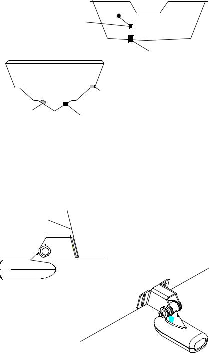
4.Hold the transducer and bracket assembly against the transom. The transducer should be roughly parallel to the ground.The bottom of the transducer bracket should be in line with the bottom of the hull. Don’t let the bracket extend below the hull! Mark the center of the slots for the mounting holes. Drill two 5/32″ holes in the marked locations for the #10 screws supplied with the transducer.
TRANSOM
SIDE VIEW
7
5.Remove the transducer from the bracket and re-assemble it with the cable passing through the bracket over the bolt as shown above. Attach the transducer to the transom. Slide the transducer up or down until it’s aligned properly on the transom as shown above. Tighten the bracket’s mounting screws. Adjust the transducer so that it’s parallel to the ground and tighten the lock nut until it touches the flat washer, then add 1/4 turn. Don’t over tighten the lock nut! If you do, the transducer won’t “kick-up” if it strikes an object in the water.
6.Route the transducer cable to the sonar unit. Make certain to leave some slack inthe cable at the transducer as shown above. If possible, route the transducer cable away from other wiring on the boat. Electrical noise from the engine’s wiring, bilge pumps, VHF radio wires and cables, and aerators can be picked up by the sonar. Use caution when routing the transducer cable around these wires.
IMPORTANT!
Clamp the transducer cable to the transom close to the transducer. This can prevent the transducer from entering the boat if it is knocked off at high speed.
7.Make a test run to determine the results. If the bottom is lost at high speed, or if noise appears on the display, try sliding the transducer bracket down. This puts the transducer deeper into the water, hopefully below the turbulence causing the noise. Don’t allow the transducer bracket to go below the bottom of the hull!
8
TROLLING MOTOR BRACKET INSTALLATION
(StrataView Only)
1.Attach the TMB-S bracket to the transducer as shown below using the hardware supplied with the transducer. (Note: The internal tooth washer is supplied with the TMB-S.)
TMB-S INTERNAL TOOTH BRACKET
WASHER
BOLT
NUT
FLAT WASHER
2.Slide the adjustable strap supplied with the TMB-S through the slot in the transducer bracket and wrap it around the trolling motor. Position the transducer to aim straight down when the motor is in the water. Tighten the strap securely. Route the transducer cable alongside the trolling motor shaft. Use plastic ties (not included) to attach the transducer cable to the trolling motor shaft. Make certain there is enough slack in the cable for the motor to turn freely. Route the cable to the sonar unit and the transducer is ready for use.
9
SHOOT-THRU-HULL
(Strata 128 and Strata 128 Plus Only)
The transducer installation inside a fiberglass hull must be in an area that does not have air bubbles in the resin or separated fiberglass layers. The sonar signal must pass through solid fiberglass. A successful transducer installation can be made on hulls with flotation materials (such as plywood, balsa wood, or foam) between layers of fiberglass if the material is removed from the chosen area. For example, some manufacturers use a layer of fiberglass, then a core of balsa wood, finishing with an outer layer of fiberglass. Removing the inner layer of fiberglass and the balsa wood core exposes the outer layer of fiberglass. The transducer can then be epoxied directly to the outer layer of fiberglass. After the epoxy cures, the hull is watertight and structurally sound. Remember, the sonar signal must pass through solid fiberglass. Any air bubbles in the fiberglass or the epoxy will reduce or eliminate the sonar signals.
To choose the proper location for thru-hull mounting, anchor the boat in 60 feet of water. Add a little water to the sump of the boat. Plug the
FILL WITH EPOXY
INNER HULL
EPOXY TO HULL FIRST
OUTER HULL
transducer into the sonar unit, turn it on, then hold the transducer over the side of the boat. Adjust the sensitivity and range controls until a second bottom echo is seen on the display. (you will need to turn both automatic and ASP off.) Don’t touch the controls once they’ve been set. Next, take the transducer out of the water and place it in the water in the sump of the boat. Observe the sonar signal to see if there is a noticeable decrease in sensitivity. The second bottom signal may disappear and the bottom signal may decrease in intensity. Move the transducer around to find the best location. If the sensitivity control has to be increased greatly to compensate, then the transducer should be mounted on the outside of the hull. If not, then mark the location that shot through the hull the best and follow the instructions on the next pages for a shoot-thru-hull mounting.
10
![]()
|
TRANSDUCER LOCATION |
TRANSDUCER LOCATION |
||||||||
|
(HIGH SPEED) |
(TROLLING SPEED) |
||||||||
Shoot-thru-hull Installation
(Strata 128 and Strata 128 Plus Only)
1. Make certain the area is clean, dry, and free of oil or grease, then sand both the inside surface of the hull and the face of the transducer with 100 grit sandpaper. The surface of the hull must be flat so the entire transducer face is in contact with the hull prior to bonding.
SPREAD EPOXY HERE
SAND THIS SURFACE
2. Follow the instructions on the epoxy package and mix it thoroughly. Do not mix it too fast, as it will cause bubbles to form in the epoxy. (NOTE! Use only the epoxies specified on the inside front cover of this manual! Failure to use one of these epoxies may result in poor sonar performance!) Apply a small amount on the face of the transducer as shown above, then spread a small amount onto the sanded area on the
11
hull. Place the transducer into the epoxy, twisting and turning it to force any air bubbles out from under the transducer face. The face of the transducer should be parallel with the hull, with a minimum amount of epoxy between the hull and transducer. After the epoxy dries, route the cable to the sonar unit.
Fish Arches
If you do not get good fish arches on your display, it could be the transducer is not parallel with the ground when the boat is at rest in the water, or at slow trolling speeds. If the arch slopes up, but not back down, then the front of the transducer is too high and needs to be lowered. If only the back half the the arch is printed, then the nose of the transducer is angled too far down and needs to be raised.
|
TRANSDUCER AIMED TOO FAR |
TRANSDUCER AIMED TOO |
|
BACK |
FAR FORWARD |
PROPER TRANSDUCER ANGLE
12
 Loading…