

Dynatel™ 2250E/2273E
Advanced Cable and
Fault Locator
Operators Manual
September 1999
78-8097-6500-7-B

|
TABLE OF CONTENTS |
|
|
Introduction ……………………………………………………………………. |
2 |
|
Installing or Replacing the Batteries …………………………………. |
2 |
|
Initial Receiver Configuration ………………………………………….. |
3 |
|
Receiver Battery Test ………………………………………………………. |
3 |
|
Transmitter Battery Test ………………………………………………….. |
4 |
|
Using External DC Power and 5 Watt Output …………………….. |
4 |
|
Locating a Buried Cable ………………………………………………….. |
5 |
|
Transmitter Setup ………………………………………………………. |
5 |
|
Receiver Setup ………………………………………………………….. |
10 |
|
Determining Cable Depth and Current ………………………………. |
13 |
|
Locating Sheath Faults…………………………………………………….. |
14 |
|
Locating an Active Duct Probe …………………………………………. |
16 |
|
Locating EMS Markers ……………………………………………………. |
17 |
|
Toning Aerial Faults ………………………………………………………… |
18 |
|
Cable or Pair Identification ………………………………………………. |
19 |
|
Optional Accessories ……………………………………………………….. |
21 |
|
Technical Information ……………………………………………………… |
22 |
Page 1
INTRODUCTION
The 3M™ Dynatel 2250E/2273E Advanced Cable and Fault Locator consists of a Transmitter and a Receiver for locating buried cables or Active Duct Probes (sondes). It also measures and pinpoints sheath faults in buried cables (2273E only) and conductor faults in aerial cables. The transmitter provides four frequencies to accommodate varying factors such as distance, cable type, or soil conditions. If desired, all four frequencies may be transmitted at once. The Transmitter also provides a separate Tone function for identifying cables and pairs. The Receiver provides four locating modes to accomplish fast or difficult tracing and to pinpoint or verify a conductor. The Receiver detects 50 or 60 Hz AC Power signals and low frequency (LF) radio signals re-radiated from local broadcast transmitters. It also measures the signal current in a conductor and displays its magnitude. The depth of buried cables or sondes may also be displayed.
Note: For more detailed locating instructions and advanced locating techniques, ask your 3M sales representative for a free publication called Cable and Pipe Locating Techniques.
INSTALLING OR REPLACING THE BATTERIES
6 ‘LR6’ cells
Caution!
Do not connect batteries improperly, charge or dispose of in fire. Batteries may leak or explode and cause personal injury. Always remove batteries when storing the units.
Battery Disposal: Since regulations vary, consult applicable regulations or authorities before disposal.
Page 2

INITIAL RECEIVER CONFIGURATION
Display depth units (inches, feet and inches, or centimeters) may be changed while holding  and pressing
  . For each press, one of three units will display. To change the passive Power frequency, press and hold
  then press
  to toggle between 50 or 60 Hz as displayed in the lower left corner of the display.
To change the Null bar graph display mode, press and hold  then
then
press to toggle between normal Null bar graph display (Null flag will flash) and inverse Null bar graph display (Null flag is solid). See section
About Trace Modes (page 11) for further information.
RECEIVER BATTERY TEST
Battery
Indicator
Battery
Mark
The Receiver batteries are tested for two seconds every time the unit is turned on. The time interval can be extended by pressing and holding  . During the battery test, the bar graph should extend to the right of the battery level mark, otherwise replace the batteries.
Note: When batteries are low, the battery test indicator  will flash.
Page 3

TRANSMITTER BATTERY TEST
|
To test the Batteries, press and hold |
. Listen to the tone and watch |
|
the display. |
•solid tone and ‘OK’ indicates batteries good;
•beeping tone and ‘LO’ indicates batteries low;
•no tone and ‘- -‘ indicates replace batteries.
Note: The battery test indicates battery condition for normal output levels. if the unit resets when the high output level is selected, use the normal output level or replace the batteries.
USING EXTERNAL DC POWER AND 5 WATT OUTPUT
The Transmitter can be operated from and external 12VDC source as well as its internal batteries. Use the supplied cigarette lighter adapter cable to connect the DC power from a vehicle’s battery source to the Transmitter’s external power jack located next to the output jack.
Note: The internal batteries will not be recharged with external DC.
5 Watt Output
An external DC source is required for 5 watt output. To select 5 watt operation, press  once for high output (3W) and again for 5 watt operation. The High Output flag will turn on for 3W and flash for 5W.
Page 4

LOCATING A BURIED CABLE
Transmitter Setup
Note: Key descriptions can be found inside the Transmitter lid.
Perform a battery test and then connect the Transmitter using one of the three methods below to put tracing signal on a cable.
Danger!
Voltage higher than 240 volts will damage equipment and cause personal injury and death. Make all direct test connections before turning on the Transmitter. Then activate the Transmitter in the Ohms mode and check the display for voltage readings. Follow standard procedures for reducing the voltage.
Warning!
Potential for electrical shock exists when handling connecting cables while the Transmitter is in the TRACE, FAULT or TONE modes. Turn the transmitter off before handling connecting cables.
Page 5
DIRECT CONNECT METHOD
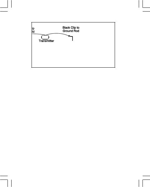
Make sure the Transmitter is off. Plug the Direct Connect Cable into the front panel jack. Connect the Black clip to the ground rod. Place the ground rod in the earth perpendicular to the suspected cable path. If necessary, extend the black lead with the Ground Extension Cable. Next, remove the ground bonding and attach the Red clip to the shield.
Note: Never attach or remove the direct connect cable from the Transmitter front panel jack while the red and black clips are connected to a cable.
Press  to turn the Transmitter on in the Ohms mode
  . It will measure the continuity of the cable under test. The results are displayed in ohms and as a tone (solid tone = good ground; beeping tone = usable ground; no tone = poor or no ground).
Note: In the ohms mode, the Transmitter can detect voltage as well as ohms. If voltage is detected, the display will alternate between displaying ohms and volts. When displaying ohms, the flag over the  will be visible. When displaying volts, the flag over the ‘V’ will be visible. When the voltage magnitude is sufficient to impair the accuracy of the ohms measurement, only voltage will be displayed. If the voltage is AC, a sine wave
  will be visible on the display. If a high AC voltage is detected, a rapid beeping tone will be heard.
Page 6

|
Press |
to select Trace mode. Press again to select one or all of the |
four frequencies. The display will alternate between displaying the selected frequency and the output signal current. It is best to choose the lowest frequency for direct connect with far-end ground and a high frequency for direct connect with no far-end ground.
|
Press |
to select high output level for longer tracing distances and |
deep cables.
Transmitter setup is finished, now go to LOCATING A BURIED
CABLE — RECEIVER SETUP (PAGE 10).
Page 7
 Loading…
Скачать
September 1999
78-8097-6500-7-B
Dynatel
™
2250E/2273E
Advanced Cable and
Fault Locator
Operators Manual

Русский
- Bedienungsanleitung 3M 2273E
- 3M 2273E User Manual
- Manual Usuario 3M 2273E
- Mode d’emploi 3M 2273E
- Istruzioni 3M 2273E
- инструкция 3M 2273E
- 3M 2273Eの取扱説明書
- Handleiding 3M 2273E
- Manual de uso 3M 2273E
Вам нужна инструкция? Мы поможем Вам ее найти и сэкономить Ваше время.
- 24 stron
- 0.24 mb
Изделие 3M 2273E, а также другие, которыми Вы пользуетесь ежедневно, наверняка вы получили в комплекте с инструкцией обслуживания. Из опыта наших пользователей мы знаем, что большинство из Вас не уделили этому особого внимания. Большая часть инструкций, сразу же после покупки попадает в корзину для мусора вместе с коробкой — это ошибка. Ознакомьтесь с информацией, касающейся инструкции 3M 2273E, которая поможет Вам в будущем сэкономить нервы и избежать головной боли.
Важная подсказка — не забывайте хотя бы раз прочитать инструкцию 3M 2273E
Если вы не хотите каждый раз читать информационные брошюры, касающиеся, тех или 3M 2273E иных изделий, достаточно, прочитать их раз — сразу же после покупки устройства. Вы получите основное знания, касающиеся поддержания изделия 3M 2273E в хорошем эксплуатационном состоянии, так, чтобы без проблем достигнуть его планируемого цикла работы. Затем инструкцию можно отложить на полку и вернуться к ней только в случае, если вы не уверены, правильно ли проводится техобслуживание изделия. Правильный уход является необходимым элементом Вашего удовольствия 3M 2273E.
Раз в году пересмотрите шкафчик, в котором держите инструкции для всех устройств, — выбросите те, которыми вы уже не пользуетесься. Это поможет Вам сохранять порядок в своей домашней базе инструкций обслуживания.
Summary of Contents for 3M 2273E
Что находится в инструкции 3M 2273E? Почему стоит ее прочитать?
- Гарантия и подробности, касающиеся техобслуживания изделия
Хорошей идеей будет прикрепить чек к странице инструкции. Если что-то плохое случится во время использования 3M 2273E, у вас будет комплект документов, необходимый для гарантийного ремонта. В этой части инструкции вы найдете информацию об авторизованных сервисных центрах3M 2273E а также, как самостоятельно правильно ухаживать за оборудованием — так, чтобы не потерять гарантийных прав. - Указания по монтажу и Setup
Не терять нервов и времени на самостоятельную попытку установки и первого запуска изделия. Воспользуйтесь рекомендациями производителя 3M 2273E чтобы правильно запустить изделие, без лишнего риска повреждения оборудования. - Информация, касающаяся дополнительных запчастей (входящих в комплект а также являющихся опцией)
Пересматривая эту часть документа вы сможете проверить, доставлен ли ваш 3M 2273E с полним комплектом аксессуаров. Вы также сможете узнать, какие дополнительные запчасти или аксессуары для 3M 2273E Вы сможете найти и докупить к своему устройству. - Troubleshooting
Самые частые проблемы, касающиеся 3M 2273E и методы их решения. Это очень полезная часть руководства по обслуживанию — она позволит Вам сэкономить много времени на поиск решений. 90% проблем с 3M 2273E повторяется у многих пользователей. - Требования, касающиеся питания и энергетический класс
Информация, касающаяся количества потребляемой энергии, а также рекомендации, касающиеся установки и питания 3M 2273E. Прочитайте, чтобы оптимально пользоваться 3M 2273E и не использовать большего количества ресурсов, нежели это необходимо для правильной работы изделия. - Специальные функции 3M 2273E
Здесь вы можешь узнать, как персонализировать изделие 3M 2273E. Вы узнаете, какие дополнительные функции могут помочь Вам удобно использовать продукт 3M 2273E а также, какие функции Вашего устройства оптимальны для выполнения конкретной деятельности.
Как видите в инструкции вы найдете информацию, которая реально поможет Вам в использовании Вашего изделия. Стоит с ней ознакомиться, чтобы избежать разочарований, возникающих из более короткого, нежели предусматривалось, периода исправности изделия 3M 2273E. Если все же вы не хотите копить инструкции в своем доме, наш сайт поможет Вам в этом — вы должны найти у нас руководство по обслуживанию большинства из своих устройств, а также 3M 2273E.
Комментарии (0)
1 Dynatel 2250E/2273E Advanced Cable and Fault Locator Operators Manual September B
2 TABLE OF CONTENTS Introduction… 2 Installing or Replacing the Batteries… 2 Initial Receiver Configuration… 3 Receiver Battery Test… 3 Transmitter Battery Test… 4 Using External DC Power and 5 Watt Output… 4 Locating a Buried Cable… 5 Transmitter Setup… 5 Receiver Setup Determining Cable Depth and Current Locating Sheath Faults Locating an Active Duct Probe Locating EMS Markers Toning Aerial Faults Cable or Pair Identification Optional Accessories Technical Information Page 1
3 INTRODUCTION The 3M Dynatel 2250E/2273E Advanced Cable and Fault Locator consists of a Transmitter and a Receiver for locating buried cables or Active Duct Probes (sondes). It also measures and pinpoints sheath faults in buried cables (2273E only) and conductor faults in aerial cables. The transmitter provides four frequencies to accommodate varying factors such as distance, cable type, or soil conditions. If desired, all four frequencies may be transmitted at once. The Transmitter also provides a separate Tone function for identifying cables and pairs. The Receiver provides four locating modes to accomplish fast or difficult tracing and to pinpoint or verify a conductor. The Receiver detects 50 or 60 Hz AC Power signals and low frequency (LF) radio signals re-radiated from local broadcast transmitters. It also measures the signal current in a conductor and displays its magnitude. The depth of buried cables or sondes may also be displayed. Note: For more detailed locating instructions and advanced locating techniques, ask your 3M sales representative for a free publication called Cable and Pipe Locating Techniques. INSTALLING OR REPLACING THE BATTERIES 6 ‘LR14’ cells 6 ‘LR6’ cells Caution! Do not connect batteries improperly, charge or dispose of in fire. Batteries may leak or explode and cause personal injury. Always remove batteries when storing the units. Battery Disposal: Since regulations vary, consult applicable regulations or authorities before disposal. Page 2
4 INITIAL RECEIVER CONFIGURATION Display depth units (inches, feet and inches, or centimeters) may be changed while holding and pressing. For each press, one of three units will display. To change the passive Power frequency, press and hold then press to toggle between 50 or 60 Hz as displayed in the lower left corner of the display. To change the Null bar graph display mode, press and hold then press to toggle between normal Null bar graph display (Null flag will flash) and inverse Null bar graph display (Null flag is solid). See section About Trace Modes (page 11) for further information. RECEIVER BATTERY TEST Battery Test Indicator Battery Level Mark The Receiver batteries are tested for two seconds every time the unit is turned on. The time interval can be extended by pressing and holding. During the battery test, the bar graph should extend to the right of the battery level mark, otherwise replace the batteries. Note: When batteries are low, the battery test indicator will flash. Page 3
5 TRANSMITTER BATTERY TEST To test the Batteries, press and hold. Listen to the tone and watch the display. solid tone and ‘OK’ indicates batteries good; beeping tone and ‘LO’ indicates batteries low; no tone and ‘- -‘ indicates replace batteries. Note: The battery test indicates battery condition for normal output levels. if the unit resets when the high output level is selected, use the normal output level or replace the batteries. USING EXTERNAL DC POWER AND 5 WATT OUTPUT The Transmitter can be operated from and external 12VDC source as well as its internal batteries. Use the supplied cigarette lighter adapter cable to connect the DC power from a vehicle’s battery source to the Transmitter’s external power jack located next to the output jack. Note: The internal batteries will not be recharged with external DC. 5 Watt Output An external DC source is required for 5 watt output. To select 5 watt operation, press once for high output (3W) and again for 5 watt operation. The High Output flag will turn on for 3W and flash for 5W. Page 4
6 LOCATING A BURIED CABLE Transmitter Setup Note: Key descriptions can be found inside the Transmitter lid. Perform a battery test and then connect the Transmitter using one of the three methods below to put tracing signal on a cable. Danger! Voltage higher than 240 volts will damage equipment and cause personal injury and death. Make all direct test connections before turning on the Transmitter. Then activate the Transmitter in the Ohms mode and check the display for voltage readings. Follow standard procedures for reducing the voltage. Warning! Potential for electrical shock exists when handling connecting cables while the Transmitter is in the TRACE, FAULT or TONE modes. Turn the transmitter off before handling connecting cables. Page 5
7 DIRECT CONNECT METHOD Make sure the Transmitter is off. Plug the Direct Connect Cable into the front panel jack. Connect the Black clip to the ground rod. Place the ground rod in the earth perpendicular to the suspected cable path. If necessary, extend the black lead with the Ground Extension Cable. Next, remove the ground bonding and attach the Red clip to the shield. Note: Never attach or remove the direct connect cable from the Transmitter front panel jack while the red and black clips are connected to a cable. Press to turn the Transmitter on in the Ohms mode. It will measure the continuity of the cable under test. The results are displayed in ohms and as a tone (solid tone = good ground; beeping tone = usable ground; no tone = poor or no ground). Note: In the ohms mode, the Transmitter can detect voltage as well as ohms. If voltage is detected, the display will alternate between displaying ohms and volts. When displaying ohms, the flag over the will be visible. When displaying volts, the flag over the ‘V’ will be visible. When the voltage magnitude is sufficient to impair the accuracy of the ohms measurement, only voltage will be displayed. If the voltage is AC, a sine wave will be visible on the display. If a high AC voltage is detected, a rapid beeping tone will be heard. Page 6
8 Press to select Trace mode. Press again to select one or all of the four frequencies. The display will alternate between displaying the selected frequency and the output signal current. It is best to choose the lowest frequency for direct connect with far-end ground and a high frequency for direct connect with no far-end ground. Press to select high output level for longer tracing distances and deep cables. Transmitter setup is finished, now go to LOCATING A BURIED CABLE — RECEIVER SETUP (PAGE 10). Page 7
9 DYNA-COUPLER METHOD Cable Path Connect the Dyna-Coupler to the Transmitter front panel jack using the coupler cable. Clamp the Dyna-Coupler around the cable below any bonds just before cable enters the earth. The jaws of the coupler must fully close. Press to turn Transmitter on. Press again to select 8 khz, 33 khz or 133 khz. Select high output level by pressing. Transmitter setup is finished, now go to LOCATING A BURIED CABLE — RECEIVER SETUP (PAGE 10). Page 8
10 INDUCTION METHOD Place the transmitter on the ground over the target cable with the lid hinge in line with the cable path. Press to turn the Transmitter on. Press again to select either 33 khz or 133 khz. For greater tracing range, select high output level by pressing. Note: If the Receiver is less than 15 meters from the Transmitter, it can pick up signal through the air. For best results, keep the Receiver away from the Transmitter by at least that distance. Transmitter setup is finished, now go to LOCATING A BURIED CABLE — RECEIVER SETUP (PAGE 10). Page 9
11 LOCATING A BURIED CABLE Receiver Setup Note: Key descriptions can be found on the side of the Receiver. Press to turn the Receiver on. Press to select the 50/60 Hz power frequency (see Selecting Passive Power Frequencies, page 12) or LF for passive locating; otherwise, select the same frequency as the Transmitter. Note: The Receiver is automatically set to Special Peak mode when LF is selected. No other modes are allowed in LF frequency. Press to adjust the speaker volume as needed: off, normal, high, or high-expanded. The high-expanded setting causes the audio to cut off below a certain threshold. Press to select a locate mode (Peak, Null, or Diff ). To select Special Peak mode: from Peak mode, press and hold then press to toggle between Peak and Special Peak modes. While in Special Peak mode, the peak flag will flash. Note: Peak, Special Peak or Null mode may require re-setting the Receiver gain. Press when the bar graph remains either fully open or fully closed. This is not necessary in differential mode since the unit automatically adjusts the receiver gain. Page 10
12 About Trace Modes Peak: In this mode, as the antenna crosses the cable, the Receiver speaker volume increases to a maximum and the bar graph fills from both sides toward the middle. As the antenna moves off the cable path, the speaker volume decreases and the bar graph opens. Peak with High-Expanded: While in Peak mode, press to select High-Expanded (the highest setting). Speaker response is cut off as the antenna moves away from the cable. Null: In this mode, the signal is a minimum directly over the cable and is maximum on either side of the cable. The speaker volume and display signal strength correspond to the signal being received. In the normal bar graph display mode (Null flag flashing) the bar graph opens at low signal strength and closes at high signal strength. In the inverse Null bar graph display mode (Null flag is on solid), the bar graph closes at low signal strength and opens at high signal strength. Differential: In this mode, the Receiver provides an indication of the relative position of the cable to the Receiver by displaying right or left arrows (the arrow points toward the cable). The bar graph increases to a maximum as the Receiver antenna is moved directly over the cable path. Speaker response is a high warbling tone to the right of the cable path, a low warbling tone to the left, and a solid tone directly over the cable. Special Peak Mode: This mode will increase the signal sensitivity of the Receiver when the signal is too weak for normal tracing. Use special attention when using this mode because it is more susceptible to congestion than the normal peak mode. Numerical Signal Strength Display Resolution: The user may select between 3 levels of signal strength resolution. The setting will be displayed on the right end of the bar graph during selection.to change the setting, press and hold the key during power up then press the key. Display resolution may be changed between the standard 1X, (no bars illuminated), 2X, (One bar illuminated), and 4X (Two bars illuminated). The unit saves the last setting until changed. Note: While tracing cables, keep the Receiver handle in line with the suspected cable path. Page 11
13 Selecting Passive Power Frequencies See section Initial Receiver Configuration (page 3) to set the power frequency to 50 Hz or 60 Hz. The Receiver can be tuned to locate 3 different harmonics of the chosen power frequency. H50 Hz or H60 Hz (high harmonic): Best for general locating of passive power. L50 Hz or L60 Hz (low harmonic): Works best on primary power cables. May be used when high harmonic is weak or erratic. 100 Hz or 120 Hz : For locating rectified AC power signals, often found on pipelines using impressed current cathodic protection. When the Power frequency is selected, the Hz symbol will flash, indicating that alternate frequencies are available. To change the selected power frequency, press and hold then press to select the next Power frequency. Selecting Auxiliary Frequencies Auxiliary frequencies are used to trace cables without using frequencies supplied by the Transmitter (2273E only). The Receiver may be able to detect these auxiliary frequencies, depending on the model: LF: General VLF locating Other frequencies for locating cables connected to a remote location transmitter with that frequency. If your Receiver has multiple auxiliary frequencies, the HZ symbol will flash when one is selected. To change the selected auxiliary frequency, press and hold the then press to select the next auxiliary frequency. Page 12
14 DETERMINING CABLE DEPTH AND CURRENT Place the Receiver Antenna on the ground directly above the cable with the handle parallel to the path. Press and the display will indicate the cable depth and relative current. Current is displayed in the lower left corner of the display. Press twice to continue tracing. You may also press to return to Trace mode. Note: During a depth-current measurement, the display will exhibit ‘ ‘ when the received signal is too low, too high, or erratic. Using Current Indications During Locating Both the Transmitter and Receiver will indicate cable current. These current indications will help to select a trace frequency, identify the correct cable and trouble shoot the set up. When using the direct connect method, the Transmitter output current number is displayed. A «LO» display, or number less than 50, indicates a weak tracing signal. A number higher than 70 represents a strong tracing signal. When the Receiver is used to find the cable near the Transmitter connection point, the current number displayed in the Receiver should correspond (within 5 points) to the Transmitter number: IF you are over the correct cable, AND most of the signal is flowing in that cable. Note: On the Transmitter every ten units on the current display represents a factor of two in current magnitude. On the Receiver, trace current readings for the additional auxiliary frequencies (except LF) are displayed in milliamps. For all other trace frequencies every ten units on the Current display represents a factor of two in current magnitude. When the Transmitter signal is applied using the Dyna-Coupler, the Transmitter current display indicates the current in the coupler and not in the cable. In order to get a measure of the cable current, point the Receiver at the exposed cable about one meter from the Dyna-Coupler. This will be the current number that should be used to identify the correct cable. Page 13
15 In general, when the Transmitter is set up to apply more current on the target cable than any other cable, the cable can easily be identified because the Receiver current reading will be highest. Note: Since some of the signal in the cable will bleed into the earth, it is expected that the Receiver current indication along the cable will decrease gradually away from the Transmitter. This effect is more pronounced at higher frequencies. LOCATING SHEATH FAULTS (2273E ONLY) Transmitter Setup Remove both the near-end and far-end shield bonds from the test section. Perform a battery test then with the Transmitter off, connect the Black clip to the ground rod. Place the ground rod behind the Transmitter, away from the faulted section, and in line with the cable path. If necessary, extend the ground lead with the Ground Extension Cable. Attach the Red clip to shield. Press to turn the Transmitter on in the Ohms mode. Measure the fault resistance. The results are displayed in ohms. Note that failure to disconnect the shield bonds at either the nearend or the far-end produces a heavy fault indication. Press again, to select the Fault mode. For maximum fault sensitivity, select high output level by pressing. Receiver Setup Press to turn the Receiver on. Press to select Fault mode. Connect the Earth Contact Frame to the accessory jack on the Receiver using the earth frame cable. Near the location of the ground rod (about one step away), insert the frame probes fully into the ground with the green-banded leg towards the fault and in line with the cable path. Press to record a fault level reference visible in the lower left corner of display. Page 14
16 The Receiver bar graph is visible on the right side (green). This indicates that the fault is ahead of the operator in the direction of the green-banded leg. Continue along the cable path, reinserting the frame probes every few steps while watching the Receiver bar graph. When the bar graph is visible on the left side (red), the fault has been passed and is now behind the operator. Move back, inserting the frame every few inches, until the bar graph returns to the green side. Turn the frame ninety degrees to the cable path. The fault is located beneath the center of the frame when the bar graph changes from one side to the other. To verify the fault location, insert the frame s red leg directly on the spot identified above. Pivot the frame in a circle around red leg re-inserting the green leg in ground every few degrees of the circle. The bar graph should always be on the left (red) indicating that the fault is directly below red leg. cable path Red leg After a fault is found and pinpointed, move the Earth Contact Frame about one frame width away from the fault and insert it into the ground with the green-banded leg towards the fault. Compare the numeric indicator reading with the fault level reference in the lower left corner of the display. If they are close, the fault is the major one. If the fault reading is 20 points less than the reference reading, multiple faults may exist. Further searching is necessary to find the fault with the highest reading. Page 15
17 LOCATING AN ACTIVE DUCT PROBE (ADP) Press to turn the Receiver on. Press to select the 33 khz frequency. Press to select the Peak mode. If you find that the received signal is too weak in this mode, try the Special Peak mode. To select Special Peak mode: from Peak mode, press and hold, then press to toggle between Peak and Special Peak modes. While in Special Peak mode, the Peak flag will flash. With the Receiver handle perpendicular to the conduit path, locate the ADP position by moving along the path until a peak is found. Press when the bar graph remains either fully open or fully closed. Refer to the ADP operating instructions for further information. Determining ADP Depth Place the Receiver Antenna on the ground directly above the located ADP position maintaining the handle orientation perpendicular to the path. Press twice to display ADP depth. To return to trace mode, press or. Note: During a depth-current measurement, the display will exhibit ‘ ‘ when the received signal is too low, too high, or erratic. Page 16
18 LOCATING EMS MARKERS EMS markers may be detected and located using either the Dynatel 2205 or 2206 EMS Marker Locating Accessory. To attach the accessory, slide the Receiver horizontally into EMS Marker Locating Accessory mounting slot. Make sure the locking button holds the Receiver securely in the slot. To separate the units, press the locking button down and slide the Receiver out of the EMS Marker Locating Accessory mounting slot. Locating Markers while Tracing Cable Path To detect markers while tracing the cable path, set the 2205 or 2206 accessory mode switch to the Alert position, and trace the cable path normally. The internal buzzer in the accessory will alert you to the proximity of a detected marker. Note: Do not use Null or Differential modes when using the 2205 or Locating Markers using the Receiver If the buzzer response is too broad, the exact marker position may be pinpointed by using the Receiver. Select 577 Hz or 33 khz on the Accessory. Use a different frequency from the tracing signal. Turn the Receiver ON, select Peak mode, and set the frequency to match the Accessory setting. Note: The initial Receiver gain in Peak mode is optimized for interfacing with the 2205 or 2206 Accessory while searching for a marker. Press only when a marker is detected and the signal is too strong. To search for a new marker, reset the Receiver gain to the initial setting by turning its power OFF and back ON, or pressing and then re-selecting the Peak mode. Refer the EMS Marker Locating Accessory operating instructions for further information. Page 17
19 TONING AERIAL FAULTS Transmitter Setup Perform a battery test; then with the Transmitter off, plug the direct connect cable into the front panel jack. If fault is a shorted pair, connect Red clip to tip and the Black clip to ring. If the fault is a cross (two pair involved), connect the Red clip to crossed conductor of one pair and the Black clip to the crossed of the other pair. If the fault is a ground, connect the Red clip to the faulted conductor and the Black clip to ground. Press to turn the Transmitter on in the Ohms mode to verify the fault. Press twice more to select the Tone mode. Press to change the high output level. Receiver Setup Press to turn the Receiver on. Press to select Tone mode. Connect a toning coil to the Receiver accessory jack. Press to select the low toning frequency (577 Hz). Move the toning coil along the cable and find a peak signal then press to adjust the Receiver gain. Press to adjust the speaker volume as needed. Follow the cable with the toning coil. An aerial fault is located at the point where the tone stops or drops off sharply. Page 18
20 CABLE OR PAIR IDENTIFICATION Transmitter Setup Transmitter setup is the same to identify cables or pairs; however, Receiver setups are different. Perform a battery test; then with the transmitter off, connect the Dyna-Coupler to the Transmitter front panel jack using the coupler cable. Note: Cable Identification requires two Dyna-Couplers: one at the Transmitter and one at the Receiver. Clamp the Dyna-Coupler around the cable or both and tip and ring of a pair and make sure the jaws fully close. Press to turn the Transmitter on and then twice more to select the Tone mode. Press to change the high output level. CABLE IDENTIFICATION Receiver Setup Press to turn the Receiver on. Press to select Tone mode. Connect a second Dyna-Coupler to the Receiver accessory jack using the earth frame cable or another coupler cable. Press to select the highest toning frequency (133 khz). Check the first cable in the group by clamping the Dyna-Coupler around the cable. Press and observe the numeric display, which is relative signal strength. Remember the number and continue by clamping the Dyna- Coupler around the next cable in the group. If the signal strength is greater than the previous observation, press. If the signal strength is less than before, ignore it. After checking all the cables in the group, the cable with the highest reading is the one being identified. Page 19
21 PAIR IDENTIFICATION Receiver Setup Press to turn the Receiver on. Press to select Tone mode. Connect the inductive probe to Receiver accessory jack using probe cable. Press to select the highest toning frequency (133 khz). Insert Probe into the bundle of pairs (or group, if known) and press. Next, divide the pairs into two bundles and insert the Probe into each of the bundles and observe the numeric display. The bundle with the highest reading will contain the target pair. Continue by dividing the bundle with the target pair into two parts and checking each part for the highest signal. In this way the target pair will be isolated. Page 20
22 OPTIONAL ACCESSORIES inch Dyna-Coupler (includes Pouch) 2200 Series Carrying Bag 2205 EMS Marker Locating Accessory (single frequencies) 2206 EMS Marker Locating Accessory (all frequencies) inch Dyna-Coupler 3011 Inductive Probe inch Dyna-Coupler Kit (includes 9011 Coupler Cable and Pouch) 3229 ADP (sonde) 9011 Coupler Cable 9023 Probe Cable 9043 Ground Extension Cable Page 21
23 TECHNICAL INFORMATION Transmitter Frequencies: Trace mode: 577 Hz, 8 khz, 33 khz, 133 khz Sheath Fault mode: 10 and 20 Hz for faults and (2273E only) 577 Hz & 33 khz for tracing Tone mode: 577 Hz & 133 khz pulsed at 8 Hz Induction mode: 33 khz and 133 khz Output Power: 3 watts maximum or 5 watts w/external DC source Battery Life: 50 hours, typical (Normal output level) 10 hours, typical (High output level) Recommended Batteries: six Duracell Alkaline size LR14 (MN1400) External DC Power: 9-18 VCD (1A) Receiver Frequencies: Active Trace/Tone: 577 Hz, 8 khz, 33 khz, 133 khz Passive Power: 50 Hz, 60 Hz (user selectable) L50/60 (5th harmonic), H50/60 (9th harmonic) 100/120 (for rectified power frequencies) Auxiliary: E Models: Passive VLF, LF 15 Khz-30 Khz E LD Models: 273 Hz, 333 Hz, LF Passive VLF: 15 khz — 30 khz Trace Modes: Dual Peak, Special Peak, Dual Null, Differential Depth Range: 0 to 914 cm (0 to 360 inches) Depth Accuracy: +10% + 1 digit for 0 to 150 cm (0 to 59 inches) +15% for 150 cm to 457 cm (60 to 180 inches) +20% for 457 cm to 914 cm (180 to 360 inches) Battery Life: 50 hours, typical Recommended Batteries: six Duracell Alkaline LR6 (MN1500) Environmental Temperature Range: Operating : -20 to 50 C (-4 to 122 F) Storage: -40 to 70 C (-40 to 158 F) Physical Receiver Weight: 1.9 kg (4.1 lbs) Transmitter Weight: 2.4 kg (5.2 lbs) Page 22
24 Dynatel is a registered trademark of 3M. Duracell is a registered trademark of Duracell Inc. This product is in accordance with the requirements of the European directive 89/336/EEC Important Notice All statements, technical information, and recommendations related to 3M s products are based on information believed to be reliable, but the accuracy or completeness is not guaranteed. Before using this product, you must evaluate it and determine if it is suitable for your intended application. You assume all risks and liability associated with such use. Any statements related to the product which are not contained in 3M s current publications, or any contrary statements contained on your purchase order shall have no force or effect unless expressly agreed upon, in writing, by an authorized officer of 3M. Warranty; Limited Remedy; Limited Liability. This product will be free from defects in material and manufacture for a period of one year from the date of purchase. 3M MAKES NO OTHER WARRANTIES INCLUDING, BUT NOT LIMITED TO, ANY IMPLIED WARRANTY OF MERCHANTABILITY OR FITNESS FOR A PARTICULAR PURPOSE. If this product is defective within the shelf life period stated above, your exclusive remedy shall be, at 3M s option, to replace or repair the 3M product or refund the purchase price of the 3M product. Except where prohibited by law, 3M will not be liable for any loss or damage arising from this 3M product, whether direct, indirect, special, incidental or consequential regardless of the legal theory asserted. Telecom Systems Division 6801 River Place Blvd. Austin, Texas Litho in USA 3M 1999

Если Вам нужна инструкция по эксплуатации трассоискателей и маркероискателей Dynatel, вы можете скачать ее на нашем сайте.
В этом разделе мы даем короткое описание и инструкции эксплуатации приборов трассопоиска следующих моделей:
- Dynatel™ 2273;
- Dynatel™ 2273E;
- Dynatel™ 2273;
- Dynatel™ 2250 M/E;
- Dynatel™ 2250 M-ID/E;
- Dynatel™ 1420;
- Dynatel™ 1420E.
Электронный кабелеискатель и искатель повреждений Dynatel™ 2273E
Электронный кабелеискатель и искатель повреждений ЗМ Dynatel™ 2273E состоит из приемника и генератора, предназначенных для определения месторасположения подземных кабелей, активных зондов и мест обрыва токопроводящих жил подвесных кабелей связи, а также рамы для поиска повреждений оболочки подземных кабелей.
Скачать инструкцию применения трассоискателя Dynatel 2273E
Скачать инструкцию применения трассоискателя Dynatel 2273E
Электронные кабелеискатели Dynatel™ 2250 M/E, 2250 M-ID/E
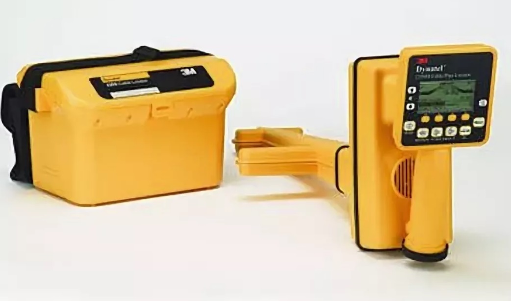
Приборы серии Dynatel™ 2250МЕ-iD для поиска кабельных линий и трубопроводов имеют все функциональные возможности, присущие предыдущим моделям Dynatel, а также возможность считывания и записи конкретной информации
пользователя в новые интеллектуальные электронные маркеры EMS iD серии 1400 шарообразной формы. Модели кабелеискателей Dynatel 2250МЕ-iD обеспечивают также возможность одновременного обнаружения двух электронных маркеров различного типа.
Электронные кабелеискатели Dynatel™ 2273 M/E, 2273 M-ID/E
Электронные приборы серии Dynatel™ 2273МЕ-iD для поиска кабельных линий и трубопроводов имеют все функциональные возможности считывания и записи конкретной информации пользователя в новые интеллектуальные электронные маркеры EMS iD серии 1400 шарообразной формы. Предварительно запрограммированная информация, такая как: идентификационный номер маркера, данные о подземных коммуникациях, название объекта, дата закладки и прочие детали, может быть считана с маркера, сохранена в памяти маркероискателя и передана из памяти маркероискателя в Ваш компьютер. Модели кабелеискателей Dynatel 2273МЕ-iD обеспечивают также возможность одновременного обнаружения двух электронных маркеров различного типа.
Электронные маркероискатели Dynatel™ 1420, 1420 E
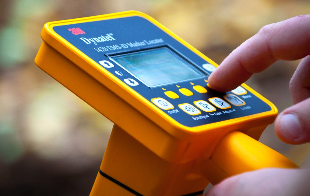
Маркероскатели Dynatel™ серии 1420 компании 3М™ имеют все функциональные возможности, присущие предыдущим моделям Dynatel, а также возможность считывания и записи конкретной информации пользователя в новые интеллектуальные электронные маркеры EMS iD серии 1400 шарообразной формы. Предварительно запрограммированная нформация, такая как: идентификационный номер маркера, данные о подземных коммуникациях, название маркируемого объекта, дата закладки и прочие детали может быть считана с маркера, сохранена в памяти маркероискателя и передана из памяти маркероискателя в Ваш компьютер, улучшая систему эксплуатации благодаря применению этого революционно нового оборудования. Искатель маркеров Dynatel серии 1420 обеспечивает также возможность одновременного обнаружения двух электронных маркеров различного типа.
Вернуться на Главную
- Manuals
- Brands
- 3M Manuals
- Circuit Tester
- Dynatel 2273M-iD Series
Manuals and User Guides for 3M Dynatel 2273M-iD Series. We have 2 3M Dynatel 2273M-iD Series manuals available for free PDF download: Operator’s Manual
3M Manuals and Guides:
The main types of 3M Dynatel 2273M-iD Series instructions: user guide — rules of useing and characteristics, service manual — repair, diagnostics, maintenance, operation manual — description of the main functions of 3M Dynatel 2273M-iD Series equipment, etc.
Most of the instructions, that you can see on the site are uploaded by our users. If you have available a manual or document for 3M Dynatel 2273M-iD Series, which is currently not on the site or present in a different language version, we ask you to upload your document on website, using the «uploading form» available to all registered users.
Характеристики
| Приемник | |
| Режим работы | Непосредственный пиковый
Непосредственный нуль Специальный пиковый |
| Активные частоты | 577 Гц
8 кГц 33 кГц 133 кГц |
| Пассивные частоты | 3,5 кГц (CATV — кабельное телевидение)
9÷30 кГц (LF) |
| Промышленные частоты | 50 Гц (5-я и 9-я гармоники)
60 Гц (5-я и 9-я гармоники) 100/120 Гц (выпрямленное значение переменного тока) |
| Внешние частоты | 273 Гц
333 Гц 340 Гц 393 Гц 400 Гц 460 Гц 512 Гц 560 Гц |
| Частоты, задаваемые пользователем | Четыре, в диапазоне 50~999 Гц |
| Дисплей | ЖК |
| Регулировка усиления | Ручная и автоматическая |
| Питание | Алкалиновые батареи типа АА (8 шт) |
| Продолжительность работы от батареи | 30 часов (среднее значение) |
| Точность определения глубины залегания | ±2 % ± 5 см для глубины 0-1,5 м
±6 % ± 5 см для глубины 1,5-3 м ±10 % ± 5 см для глубины 3-4,5 м |
| Глубина обнаружения | 0-924 см |
| Температура эксплуатации | -20°C … +50°C |
| Температура хранения | -20°C … +70°C |
| Уровень пыле- влагозащищенности | IP 54 |
| Габаритные размеры, мм | 286x197x172 |
| Масса, кг | 2,3 |
| Маркероискатель | |
| Типы маркеров (устанавливаются при начальном конфигурировании) | Общего назначения
Коммуникации Газопровод Телефония Водопровод Канализация Силовой кабель |
| Дальность обнаружения | Согласно характеристикам маркеров |
| Дальность считывания данных (шаровые маркеры XR-iD) | Все типы, кроме маркера для силового кабеля — 1,5 м
Маркер для силового кабеля — 1 м |
| Дальность программирования (шаровые маркеры XR-iD) | 30 см |
| Точность определения глубины залегания маркера | ±15 % ± 5 см |
| Режим обнаружения двух типов маркеров | Любые два типа маркеров |
| Генератор | |
| Режим поиска трассы | 577 Гц
8 кГц 33 кГц 133 кГц |
| Режим поиска повреждения | 10/20 Гц – поиск повреждения
577 Гц/33 кГц – поиск трассы |
| Тональный режим | 577 Гц
133 кГц |
| Индукционный режим | 8 кГц
33 кГц 133 кГц |
| Выходная мощность | 12 Вт |
| Питание | Алкалиновые батареи типа С (LR14) (6 шт)
Аккумуляторная батарея 2200RB Внешний источник питания 9–18 В |
| Продолжительность работы от батареи | 40 часов (нормальный уровень мощности передачи)
10 часов (высокий уровень мощности передачи) |
| Температура эксплуатации | -20°C … +50°C |
| Температура хранения | -20°C … +70°C |
| Уровень пыле-влагозащищенности | IP 54 |
| Габаритные размеры, мм | 172x286x197 |
| Масса генератора, кг | 2,4 |
| Масса приемника, кг | 2,3 |
Комплектация
| Приемник 2273M-iD | 1 шт. |
| Генератор 2273M-E12WT 12 Вт | 1 шт. |
| Стержень заземления | 1 шт. |
| Комплект Locator Coupler:
— индукционные клещи Dyna-Coupler (размер 3») — кабель подключения индукционных клещей — чехол для клещей |
1 шт. |
| Кабель гальванического подключения с малыми зажимами (1,5 м) | 1 шт. |
| Кабель гальванического подключения с большими зажимами (3 м) | 1 шт. |
| Перезаряжаемая аккумуляторная батарея 2200RB (для генератора) | 1 шт. |
| Кабель для зарядки от автомобильного прикуривателя | 1 шт. |
| А-рамка | 1 шт. |
| Кабель для подключения А-рамки | 1 шт. |
| Сумка для переноски | 1 шт. |
| Инструкция по эксплуатации | 1 шт. |
Логистические параметры
| Объем, м3: | 0,185130 |
| Вес, кг.: | 16 |
Here you can view all the pages of manual 3M Dynatel 2273 Advanced Cable and Fault Locator User Manual. The 3M manuals for Locator are available online for free. You can easily download all the documents as PDF.
Page 1

September 1999
78-8097-6517-1-B
Dynatel™ 2273
Advanced Cable and
Fault Locator
Operators Manual
Page 2

TABLE OF CONTENTS
Introduction ............................................................................... 2
Installing or Replacing the Batteries ........................................ 2
Initial Receiver Configuration .................................................. 3
Receiver Battery Test ................................................................ 3
Transmitter Battery Test ........................................................... 4
Using External DC Power and 5 Watt Output...
Page 3

INTRODUCTION
The 3M™ Dynatel™ 2273 Advanced Cable and Fault Locator consists of a
Transmitter and a Receiver for locating buried cables or Active Duct
Probes (sondes). It also measures and pinpoints sheath faults in buried
cables and conductor faults in aerial cables. The Transmitter provides four
frequencies to accommodate varying factors such as distance, cable type,
or soil conditions. If desired, all four frequencies may be transmitted at
once. The Transmitter also provides a separate Tone function...
Page 4

INITIAL RECEIVER CONFIGURATION
Display depth units (inches, feet and inches, or centimeters) may be
changed while holding
 and pressing .  For each press, one of
three units will display. To change the passive Power frequency, press and
hold
 then press  to toggle between 50 or 60 Hz as displayed in
the lower left corner of the display.
To change the Null bar graph display mode, press and hold
then
press
 to toggle between normal Null bar graph display (Null flag will
flash) and inverse Null bar...
Page 5

TRANSMITTER BATTERY TEST
To test the Batteries, press and hold .   Listen to the tone and watch
the display.
• solid tone and OK indicates batteries good;
• beeping tone and LO indicates batteries low;
• no tone and - - indicates replace batteries.
Note:   The battery test indicates battery condition for normal output
levels.  If the unit resets when the high output level is selected, use the
normal output level or replace the batteries.
USING EXTERNAL DC POWER AND 5 WATT OUTPUT
If the unit has the...
Page 6

LOCATING A BURIED CABLE
Transmitter Setup
Note: Key descriptions can be found inside the Transmitter lid.
Perform a battery test and then connect the Transmitter using one of the
three methods below to put tracing signal on a cable.
DANGER!
Voltage greater than 240 volts will damage equipment and cause
personal injury and death.  Make all direct test connections before
turning on the Transmitter.  Then activate the Transmitter in the Ohms
mode and check the display for voltage readings.  Follow standard...
Page 7

Make sure the Transmitter is off. Plug the direct connect cable into the
front panel jack.  Connect the Black clip to the ground rod.  Place the
ground rod in the earth perpendicular to the suspected cable path.  If
necessary, extend the black lead with the Ground Extension Cable.  Next,
remove the ground bonding and attach the Red clip to the shield.
Press         to turn the Transmitter on in the Ohms mode
.  It will
measure the continuity of the cable under test.  The results are displayed in
ohms...
Page 8

Press  to select Trace mode.  Press again to select one or all of the
four frequencies. The display will alternate between displaying the
selected frequency and the output signal current. It is best to choose the
lowest frequency for direct connect with far-end ground and a high
frequency for direct connect with no far-end ground.
Press
 to  select high output level for longer tracing distances and
deep cables.
Transmitter setup is finished, now go to LOCATING A BURIED
CABLE - R
ECEIVER SETUP (Page...
Page 9

Dyna-Coupler Method
Cable Path
Connect the Dyna-Coupler to the Transmitter front panel jack using the
coupler cable.
Clamp the Dyna-Coupler around the cable below any bonds just before the
cable enters the earth. The jaws of the coupler must fully close.
Press  to turn Transmitter on. Press again to select 8 kHz, 33kHz, or
200 kHz.
Select high output level by pressing  .
Transmitter setup is finished, now go to LOCATING A BURIED CABLE
- Receiver Setup (Page 10).
Page 8
Page 10

Induction Method
Place the transmitter on the ground over the target cable with the lid hinge
in line with the cable path.  Press
 to turn the Transmitter on.
Press again to select either 33 kHz or 200 kHz. For greater tracing range,
select high output level by pressing
.
Note:  If the Receiver is less than 50 feet from the Transmitter, it can pick
up signal through the air.  For best results, keep the Receiver away from
the Transmitter by at least that distance.
Transmitter setup is finished, now go...
Start reading 3M Dynatel 2273 Advanced Cable and Fault Locator User Manual
Related Manuals for 3M Dynatel 2273 Advanced Cable and Fault Locator User Manual
All 3M manuals