
Описание Deep Sea DSE 6020 MKII
Панель управления DSE6020 является универсальный контроллером для работы на дизельных, бензиновых и газовых электростанциях. Данная панель управления позволяет следить за состоянием электростанции, запускать генераторную установку в автоматическом режиме, обеспечить удаленный мониторинг посредством различных вариантов коммуникаций. Панель DSE6020 оборудована встроенным детектором фаз, имеет USB разъём для подключения периферийного оборудования и PC компьютера.
Панель управления DSE6020 контролирует скорость двигателя, частоту напряжения, силу тока, давление масла, температуру ОЖ и уровень топлива, выводит аварийные ошибки и предупреждения на монитор и ЛЕД-индикаторы.
DSE6020 имеет CAN-соединение с блоком управления двигателем. Так же есть вход для подключения датчика PICK-UP и электронного регулятора оборотов. Панель DSE6020 можно легко настроить под различные условия эксплуатации с помощью оригинального программного обеспечения DSE Configuration Suite. Так же имеется возможность настройки параметров с передней панели без применения оригинального программного обеспечения.
Возможности:
- LCD-дисплей с подсветкой
- аварийные сигналы выводимые на LCD-дисплей и ЛЕД-индикаторы
- энергонезависимая память
- подключение CAN-шины и датчика скорости
- настройка панели с помощью оригинального программного обеспечения DSE Configuration Suite
- настраиваемые параметры и задержки
- возможность настройки альтернативной конфигурации
- журнал ошибок
- возможность запуска оборудования по удаленному сигналу
- контроль выходного напряжения
- контроль мощности (кВт, кВА, кВар)
- контроль за внешней сетью для автоматического запуска электростанции
- кнопка «Тест»
- контроль за напряжение аккумуляторной батареи
- управление подогревателем двигателя
- счетчик моточасов
Преимущества:
- управление сетевыми и генераторными контакторами щита АВР
- счетчик моточасов позволяет контролировать общую наработку генераторной установки и двигателя
- дружественный интерфейс для оператора позволяет отслеживать сразу несколько параметров электростанции
- модуль DSE6020 может быть настроен под индивидуальные требования и особенности оборудования
- корпус IP65
Обзор марки Deep Sea
С 2001 на рынке
Мы успешно реализуем энергетические решения уже 20 лет и накопили опыт решения самых сложных задач
Сервисная служба
Мы обладаем собственной мобильной службой сервиса и ремонта оборудования
Большой склад
Наш склад — это более тысячи наименований оригинальных запчастей и различных расходных элементов
Гарантия качества
Все наши решения защищены и проверены одной из крупнейших СРО. Ответственность застрахована

27430,00 ₽
DSE6020 MK2 Контроллер Deep Sea Модуль автоматического управления сетью
Количество товара DSE6020 MKII Контроллер Deep Sea

-
Описание
-
Бренд
ИНСТРУКЦИЯ Deep Sea DSE6020 MKII
DSE6010-MKII-DSE6020-MKII-Data-Sheet
DSE 6020 MKII Контроллер Deep Sea – предназначен для управления одной генераторной установкой. Контроллер автоматического ввода резерва (АВР).
Характеристики:
- Автоматическое переключение между сетью и генератором
- Счетчик моточасов
- Удобная настройка при помощи кнопок на лицевой панели
- Подсветка экрана; одновременный вывод на экран нескольких параметров
- Гибкая настройка контроллера позволяет адаптировать его к нестандартным требованиям
- Совместимость с большим количеством двигателей CAN (двигателя с ECM), включая 4 уровень
- Для настройки контроллера применяется ПО DSE Configuration Suite
- Лицензионное программное обеспечение для ПК, поставляется бесплатно
- устойчивость к проникновению воды IP65 (с применением прокладки, лицевая панель)
- Подсветка экрана
- Доступна опция с подогревателем дисплея
- Полностью настраивается кнопками на лицевой панели или с помощью DSE Configuration Suite по USB
- Режим энергосбережения
- Мониторинг трех фаз генератора
- Мониторинг трех фаз сети
- Мониторинг тока и мощности (кВт, кВ A, кВ Ar, pf)
- Счетчики выработанной мощности (кВт ч, кВА h, кВAr h) — для технического учета
- Защита от перегрузки генератора (КВт)
- Управление силовым выключателем выключателем с лицевой панели контроллера
- Настраиваемые выхода стартера и топливного соленойда даже при использовании CAN линии для связи с двигателем
- 4 настраиваемых выхода постоянного тока
- 4 настраиваемых аналоговых / цифровых входа
- 6 настраиваемых цифровых входов
- Поддержка датчиков 0-10 В и 4-20 мА
- Настраиваемая поэтапная загрузка генератора
- Контроль и управление частотой и напряжением генератора
- Защита двигателя
- Функция управления подогревом двигателя
- Функция управления холостым ходом двигателя
- Управление топливным насосом
- Часы реального времени
- Контроль напряжения АКБ
- Предупреждение, отключение нагрузки, останов двигателя при неисправности
- Конфигурируемый журнал событий на 50 ячеек
Купить DSE6020 MKII Контроллер Deep Sea с доставкой по России. С услугой доставки и установки на ваше оборудование по всей территории России.
Бренд
Deep Sea Electronics
Компания Deep Sea Electronics является одним из ведущих мировых производителей контроллеров генераторов, контроллеров автоматического переключения, зарядных устройств для аккумуляторов и контроллеров транспортных средств и внедорожников. Продукция продается в 150 странах напрямую из головного офиса в Великобритании и через обширную дистрибьюторскую сеть.
 Contact DSE® Sales & Support

DSE UK
T: +44 (0) 1723 890099
E: sales@deepseaelectronics.com
E: support@deepseaelectronics.com

DSE USA
T: +1 (815) 316-8706
E: usasales@deepseaelectronics.com
E: support@deepseaelectronics.com

DSE DUBAI
T: +971 (0) 45 910819
E: uaesales@deepseaelectronics.com

DSE INDIA
T: +91 (0)20 68195900
E: support@deepseaelectronics.com
Highfield House, Hunmanby Industrial Estate,
Hunmanby, North Yorkshire YO14 0PH
England
Products
DSEGenset®
DSEControl® DSEPower®
DSEAts®
About Us
Videos
News
Case Studies
Careers
Support
Product Software
Product Downloads
Support FAQs
Genset Non-Standard/Obsolete
Control Non-Standard/Obsolete
ATS Non-Standard/Obsolete
Power Non-Standard/Obsolete
Purchasing Terms & Conditions
Contact
Technical Support
Sales Support
Distributors
CAREERS
Log In
|
Register
Contact
Technical Support
Sales Support
Distributors
CAREERS
Log In
|
Register
Case Studies
Newsletter
Subscribe to our newsletter
Please enter a valid email address.
WEEE TAKE BACK |
Terms and Conditions / Privacy Policy
Modern Slavery Statement |
Code of
Conduct |
ISO9001: 2015 |
ISO14001: 2015
Registered in England & Wales 01319649 | VAT 3169 234 57
© Deep Sea Electronics 2023 |
Designed by Design Junkie
Содержание
- Deep sea electronics dse 6020 схема подключения
- Тип изделия
- Стандартные функции
- Управление двигателем
- Контроль работы двигателя
- Контроль работы генератора
- Защита генератора
- Данные отображаемые на графическом дисплее
- Журнал событий
- Настройка контроллера
- Deep sea electronics dse 6020 схема подключения
- Auto Mains (Utility) Failure Control Modules
- DSE 6020
- Request a Quote
- Product Highlights
- Key Features
- Key Features
- Specification
- Environmental Testing Standards
- Related Products
- Product Variants
- WEEE Distributor Take Back Scheme
- DC SUPPLY
- GENERATOR & MAINS (UTILITY)
- INPUTS
- OUTPUTS
- Environmental Testing Standards
- Connection Diagram
- Related Products
- DSE 124
- DSE 890
- DSE 891
- DSE 892
- DSE 855
- Product Variants
- WEEE Distributor Take Back Scheme
- SEA ELECTRONICS Руководство Оператора DSE6010 MKII и DSE6020 MKII Номер Документа 057-230 057-230 ИЗДАНИЕ 1 SEA ELECTRONICS Фирма Deep Sea Electronics Plc (стр. 1 )
- Руководство Оператора DSE6010 MKII и DSE6020 MKII

Модуль автоматического определения нарушений в сети модели DSE 6020 предназначен для того, чтобы дать возможность производителю обеспечить выполнение сложных современных требований данной отрасли. Он предназначен, главным образом, для контроля наличия электроснабжения от сети (энергосистемы), для запуска генератора автоматически в случае выхода сети из заданных пределов. При необходимости генератор можно запускать и останавливать вручную, пользователь также может переключать нагрузку на генератор либо вручную с помощью внешних кнопок, либо автоматически. Пользователь также имеет возможность просматривать все рабочие параметры системы на ЖКИ-дисплее.
Тип изделия
Модуль DSE 6020 контролирует сеть (энергосистему), выдавая информацию о статусе её работы на встроенном в модуль ЖКИ-дисплее. Кроме того, модуль также контролирует двигатель, сообщая о его рабочем состоянии и об аварийных ситуациях, автоматически выключая двигатель и передавая первое по поступлению сообщение об аварийном состоянии двигателя в виде мигания светодиода общей сигнализации. Точная информация о характере нарушений в сети демонстрируется совместно включением скрытых до момента необходимости светодиодов и ЖКИ-дисплея на передней панели.
Мощный 16-битовый микропроцессор, установленный в модуле, позволяет вводить в модуль целый ряд сложных функций в качестве стандартного исполнения, в том числе, модуль имеет:
- ЖКИ на основе иконок (устраняющий необходимость перевода команд и использования языков).
- Контроль величины напряжения, тока и мощности.
- Контроль параметров двигателя.
- Полностью конфигурируемые входы, используемые в качестве сигнальных устройств или для исполнения ряда различных функций.
- Широкий диапазон выходных функций, в которых используются встроенные релейные выходы или имеется расширение состава реле.
Выбираемые алгоритмы работы, таймеры и аварийные отключения могут быть изменены пользователем с персонального компьютера, в котором используются программное обеспечение серии 7300 для конфигурирования и интерфейс P810.
Модуль размещён в прочном пластмассовом корпусе, предназначенном для установки на передней панели. Соединения осуществляются посредством штекерных разъёмов с защёлкой.
Стандартные функции
Управление двигателем
- Задержка пуска
- Предварительный разогрев
- Попытка прокручивания
- Пауза при прокручивании
- Разогрев
- Прогон для охлаждения
- Задержка соленоида (вкл. для останова)
Контроль работы двигателя
- Низкое давление масла
- Высокая температура охлаждающей жидкости
- Низкий уровень топлива
- Неисправность зарядного генератора
- Пониженная частота вращения
- Разнос/превышение скорости
Контроль работы генератора
- Низкое напряжение генератора
- Высокое напряжения генератора
- Пониженная частота генератора
- Превышение частоты генератора
- Превышение тока
- Задержка переходного процесса генератора
Защита генератора
- Повышение/понижение напряжения
- Повышение/понижение частоты
- Перегрузка по току
- Обратная мощность
Данные отображаемые на графическом дисплее
- Число оборотов (об/мин)/частота генератора (Гц)
- Напряжение переменного тока «линия-нейтраль»
- Напряжение переменного тока «линия-линия»
- Давление масла
- Температура охлаждающей жидкости
- Уровень топлива (%)
- Время наработки двигателя
- Напряжение аккумуляторных батарей
- Величина линейного тока переменного напряжения
- Общая мощность (кВт)
- Общая мощность (кВА)
- Угол сдвига фаз напряжения переменного тока (cosφ)
- Частота в сети (Гц)
- Напряжение в сети «линия-нейтраль»
- Напряжение в сети «линия-линия»
Журнал событий
Настройка контроллера
ПО для конфигурирования на основе ПК позволяет быстро, просто и надёжно конфигурировать параметры модуля. При использовании интерфейса P810 для создания безопасной, изолированной от посторонних, связи с ПК специалисты с допуском могут легко производить изменения в системе. Все сделанные настройки могут быть сохранены и затем загружаться с диска или выводится на печать для анализа. Устройства диагностики позволяют находить неисправности и осуществлять контроль во время тестирования и настройки. Кроме того, можно осуществлять изменение уставок и времени параметров защит при помощи кнопок на передней панели.
Программное обеспечение ПК серии 73хх, разработано на основе программы MS Windows, позволяет оператору управлять модулем на расстоянии. Оператор также может дистанционно просматривать измерения, сведения об аварийных ситуациях, журнал событий, а также состояние реле и входов.
Модуль DSE 6020 может предоставить пользователю полный набор телеметрических устройств посредством дополнительного коммуникационного программного обеспечения. Модуль может быть подключен к ПК через интерфейс 810 или через соответствующий модем.
Источник
Deep sea electronics dse 6020 схема подключения
We use cookies to ensure that we give you the best experience on our website. If you continue without changing your setting, we’ll assume that you have accepted the use of cookies on our website. However, you can change your cookie settings at any time. Click ‘continue’ to hide this message.
Auto Mains (Utility) Failure Control Modules
DSE 6020
Auto Mains (Utility) Failure Control Module
Request a Quote
Product Highlights
Key Features
Key Features
Specification
Environmental Testing Standards
No related products available
Product Variants
No product variants available

WEEE Distributor Take Back Scheme
RECYCLING YOUR OLD ELECTRICALS IS EASY!
Recycle your electrical and electronic devices for free at your local recycling centre (UK Only). To find your nearest recycling centre visit the Recycle More website and enter your postcode.
WHY SHOULD YOU RECYCLE?
Unwanted electrical equipment is the UK’s fastest growing type of waste. Many electrical items can be repaired or recycled, saving natural resources and the environment. To remind you that old electrical equipment can be recycled it is marked with a crossed out wheelie bin symbol. Please do not throw any electrical equipment (including those marked with this symbol) in your bin.
WHAT IS WEEE?
The Waste Electrical or Electronic Equipment (WEEE) Directive required countries to maximise separate collection and environmentally friendly processing of these items.
HOW ARE DSE HELPING?
In the UK, suppliers of electronics, such as DSE must provide a system which allows all customers buying new electrical equipment the opportunity to recycle old items free of charge. As a responsible supplier, we have met the requirements placed on us by financially supporting the network of WEEE recycling centres established by local authorities. This is achieved by supporting through membership of the national Distributor Take Back Scheme (DTS). To find out more information on WEEE recycling and to locate your nearest recycling centre please visit the Recycle More website.
DSE WEEE Registration Number — WEE/BE0052TQ
Источник
DC SUPPLY
CONTINUOUS VOLTAGE RATING
8 V to 35 V Continuous
CRANKING DROPOUTS
Able to survive 0 V for 50 mS, providing supply was at least 10 V before dropout and supply recovers to 5 V. This is achieved without the need for internal batteries. LEDs and backlight will not be maintained
during cranking.
MAXIMUM OPERATING CURRENT
100 mA at 12 V, 105 mA at 24 V
MAXIMUM STANDBY CURRENT
60 mA at 12 V, 55 mA at 24 V
MAXIMUM SLEEP CURRENT
40 mA at 12 V, 35 mA at 24 V
GENERATOR & MAINS (UTILITY)
VOLTAGE RANGE
15 V to 415 V AC (Ph to N)
26 V to 719 V AC (Ph to Ph)
FREQUENCY RANGE
3.5 Hz to 75 Hz
INPUTS
DIGITAL INPUTS A to F
Negative switching
ANALOGUE INPUTS A to C
Configurable as:
Negative switching digital input
0 Ω to 480 Ω
ANALOGUE INPUT D
Configurable as:
Negative switching digital input
0 V to 10 V
4 mA to 20 mA
0 Ω to 480 Ω
OUTPUTS
OUTPUT A (FUEL)
10 A short term, 5 A continuous,
at supply voltage
OUTPUT B (START)
10 A short term, 5 A continuous,
at supply voltage
AUXILIARY OUTPUTS C, D, E & F
2 A DC at supply voltage
Environmental Testing Standards
ELECTRO-MAGNETIC COMPATIBILITY
BS EN 61000-6-2
EMC Generic Immunity Standard for the Industrial Environment.
BS EN 61000-6-4
EMC Generic Emission Standard for the Industrial Environment.
ELECTRICAL SAFETY
BS EN 60950
Safety of Information Technology Equipment, including Electrical Business Equipment.
TEMPERATURE
BS EN 60068-2-1
Ab/Ae Cold Test -30°C.
BS EN 60068-2-2
Bb/Be Dry Heat +70°C.
VIBRATION
BS EN 60068-2-6
Ten sweeps in each of three major axes.
5 Hz to 8 Hz @ +/-7.5 mm, 8 Hz to 500 Hz @ 2 gn.
HUMIDITY
BS EN 60068-2-30
Db Damp Heat Cyclic 20/55° C @ 95% RH 48 Hours.
BS EN 60068-2-78
Cab Damp Heat Static 40° C @ 93% RH 48 Hours.
SHOCK
BS EN 60068-2-27
Three shocks in each of three major axes 15 gn in 11 ms.
DEGREES OF PROTECTION PROVIDED BY ENCLOSURES
BS EN 60529
IP65 — Front of module when installed into the control panel with the optional sealing gasket.
Connection Diagram
DSE 124
DSE 890
DSE WebNet® Gateway — 3G (GSM)/Ethernet
DSE 891
DSE WebNet® Gateway — Ethernet Only
DSE 892
Simple Network Management Protocol (SNMP) Gateway
DSE 855
USB to Ethernet Communications Device
Product Variants
6020-03 — MKII Auto Mains (Utility) Failure Control Module
6020-04 — MKII Auto Mains (Utility) Failure Control Module (Htr)
WEEE Distributor Take Back Scheme
RECYCLING YOUR OLD ELECTRICALS IS EASY!
Recycle your electrical and electronic devices for free at your local recycling centre (UK Only). To find your nearest recycling centre visit the Recycle More website and enter your postcode.
WHY SHOULD YOU RECYCLE?
Unwanted electrical equipment is the UK’s fastest growing type of waste. Many electrical items can be repaired or recycled, saving natural resources and the environment. To remind you that old electrical equipment can be recycled it is marked with a crossed out wheelie bin symbol. Please do not throw any electrical equipment (including those marked with this symbol) in your bin.
WHAT IS WEEE?
The Waste Electrical or Electronic Equipment (WEEE) Directive required countries to maximise separate collection and environmentally friendly processing of these items.
HOW ARE DSE HELPING?
In the UK, suppliers of electronics, such as DSE must provide a system which allows all customers buying new electrical equipment the opportunity to recycle old items free of charge. As a responsible supplier, we have met the requirements placed on us by financially supporting the network of WEEE recycling centres established by local authorities. This is achieved by supporting through membership of the national Distributor Take Back Scheme (DTS). To find out more information on WEEE recycling and to locate your nearest recycling centre please visit the Recycle More website.
DSE WEEE Registration Number — WEE/BE0052TQ
Источник
SEA ELECTRONICS Руководство Оператора DSE6010 MKII и DSE6020 MKII Номер Документа 057-230 057-230 ИЗДАНИЕ 1 SEA ELECTRONICS Фирма Deep Sea Electronics Plc (стр. 1 )
 |
Из за большого объема этот материал размещен на нескольких страницах: 1 2 3 4 5 6 7 8 9 10 11 12 13 14 15 16 17 18 19 20 21 22 23 24 25 26 |


SEA ELECTRONICS Руководство Оператора
DSE6010 MKII и DSE6020 MKII
Номер Документа: 057-230
Автор: Марк Грэхэм

057-230 ИЗДАНИЕ: 1

Deep Sea Electronics Plc
North Yorkshire O14 0PH
Sales Tel: +44 (0) 1723 890099
Sales Fax: +44 (0) 1723 893303
Фирма «Deep Sea Electronics Plc»
Ханмэнби, Хайфилд Хаус
Тел. Отдела продаж: +44 (0) 1723 890099
Факс Отдела продаж: +44 (0) 1723 893303
Эл. Почта: sales@deepseaplc.com
Руководство Оператора DSE6010 MKII и DSE6020 MKII
© «Deep Sea Electronics Plc»
Все права сохраняются. Размножать какие-либо разделы данной документации в какой-либо материальной форме (в том числе: путем фотокопирования или сохранения на электронных носителях или иными средствами) без письменного на то разрешения обладателя авторских прав, за исключением случаев, подпадающих под действие положений закона от 1988 г. об авторских правах, промышленных образцах и патентах, запрещается.
Заявки на получение письменного разрешения от владельца авторских прав на размножение каких-либо разделов данного документа следует направлять на фирму «Deep Sea Electronics Plc» по вышеуказанному адресу.
Логотип DSE является зарегистрированным в Великобритании товарным знаком Sea Electronics».
Все ссылки на фирменные названия изделий в настоящей публикации является собственностью соответствующих фирм.
Sea Electronics» оставляет за собой право на внесение изменений в содержание данного документа без предварительного уведомления.
Изменения, Внесенные с Момента Последней Публикации
Источник
- Manuals
- Brands
- Aksa Manuals
- Control Panel
- DSE 6020 AMF
Manuals and User Guides for Aksa DSE 6020 AMF. We have 1 Aksa DSE 6020 AMF manual available for free PDF download: Operating Manual
-
DEEP SEA ELECTRONICS PLC
DSE60xx Series Control Module
Document Number 057-112
Author : Anthony Manton
-
DSE Model 60xx Series Control and Instrumentation System
Operators Manual2 Part No. 057-112 60xx Series OPERATING MANUAL ISSUE 3
13/04/2011 ADMDeep Sea Electronics Plc Highfield House Hunmanby North
Yorkshire YO14 0PH ENGLANDSales Tel: +44 (0) 1723 890099 Sales Fax: +44 (0) 1723
893303E-mail: [email protected] Website: www.deepseaplc.com
DSE Model 60xx series Control and Instrumentation System
Operators ManualDeep Sea Electronics Plc All rights reserved. No part of this
publication may be reproduced in any material form (including
photocopying or storing in any medium by electronic means or other)
without the written permission of the copyright holder except in
accordance with the provisions of the Copyright, Designs and
Patents Act 1988. Applications for the copyright holders written
permission to reproduce any part of this publication should be
addressed to Deep Sea Electronics Plc at the address above.The DSE logo and the names are UK registered trademarks of Deep
Sea Electronics PLC.Any reference to trademarked product names used within this
publication is owned by their respective companies.Deep Sea Electronics Plc reserves the right to change the
contents of this document without prior notice.Amendments since last publication
Amd. No. Comments Issue 1 First release Issue 2 Added fast
loading and changes to flexible sensor alarms in the front panel
configuration table. Issue 3 Added Power pages front panel Watts /
kVA / kVArClarification of notation used within this publication.
NOTE:
Highlights an essential element of a procedure to ensure
correctness.CAUTION!
Indicates a procedure or practice, which, if not strictly
observed, could result in damage or destruction of equipment.WARNING!
Indicates a procedure or practice, which could result in injury
to personnel or loss of life if not followed correctly. -
DSE Model 60xx Series Control & Instrumentation System
Operators ManualPart No. 057-112 60xx Series Mk2 OPERATING MANUAL ISSUE 3
13/04/2011 ADM 3TABLE OF CONTENTS
Section Page 1 BIBLIOGRAPHY
………………………………………………………………………………….
51.1 INSTALLATION INSTRUCTIONS
……………………………………………………………………………
5 1.2 MANUALS
…………………………………………………………………………………………………………….
52 INTRODUCTION
………………………………………………………………………………….
5 3 SPECIFICATIONS
………………………………………………………………………………..
63.1 PART NUMBERING
………………………………………………………………………………………………
6 3.1.1 SHORT NAMES
………………………………………………………………………………………………
63.1 POWER SUPPLY REQUIREMENTS
……………………………………………………………………….
7 3.2 TERMINAL SPECIFICATION
………………………………………………………………………………….
7 3.3 GENERATOR VOLTAGE / FREQUENCY SENSING
………………………………………………… 7 3.4
INPUTS
………………………………………………………………………………………………………………..
83.4.1 DIGITAL INPUTS
…………………………………………………………………………………………….
8 3.4.2 ANALOGUE INPUTS
……………………………………………………………………………………….
8 3.4.3 CHARGE FAIL INPUT
……………………………………………………………………………………..
9 3.4.4 MAGNETIC PICKUP
………………………………………………………………………………………..
93.5 OUTPUTS
…………………………………………………………………………………………………………….
9 3.5.1 OUTPUTS A & B (FUEL AND
START)……………………………………………………………….
9 3.5.2 CONFIGURABLE OUTPUTS C, D, E & F
…………………………………………………………..
93.6 COMMUNICATION PORTS
……………………………………………………………………………………
9 3.7 ACCUMULATED
INSTRUMENTATION……………………………………………………………………
9 3.8 DIMENSIONS AND MOUNTING
……………………………………………………………………………
103.8.1 DIMENSIONS
……………………………………………………………………………………………….
10 3.8.2 PANEL CUTOUT
…………………………………………………………………………………………..
10 3.8.3
WEIGHT……………………………………………………………………………………………………….
10 3.8.4 FIXING CLIPS
……………………………………………………………………………………………….
10 3.8.5 OPTIONAL SILICON SEALING GASKET
…………………………………………………………
103.9 APPLICABLE STANDARDS
…………………………………………………………………………………
114 INSTALLATION
………………………………………………………………………………….
12 4.1 TERMINAL DESCRIPTION
…………………………………………………………………………………..
124.1.1 DC SUPPLY, FUEL AND START OUTPUTS
……………………………………………………. 12
4.1.2 ANALOGUE SENSORS
………………………………………………………………………………….
13 4.1.3 MAGNETIC PICKUP
………………………………………………………………………………………
13 4.1.4 CAN
……………………………………………………………………………………………………………..
14 4.1.5 GENERATOR / MAINS VOLTAGE SENSING
…………………………………………………… 14
4.1.6 GENERATOR CURRENT TRANSFORMERS
………………………………………………….. 15
4.1.7 DIGITAL INPUTS
…………………………………………………………………………………………..
16 4.1.8 PC CONFIGURATION INTERFACE CONNECTOR
………………………………………….. 164.2 TYPICAL WIRING DIAGRAMS
……………………………………………………………………………..
17 4.2.1 DSE 6010 MK2 AUTOSTART MODULE
…………………………………………………………..
17 4.2.2 DSE 6020 MK2 AUTO MAINS FAILURE MODULE
…………………………………………… 185 DESCRIPTION OF CONTROLS
…………………………………………………………..
19 5.1 QUICKSTART GUIDE
………………………………………………………………………………………….
205.1.1 STARTING THE ENGINE
……………………………………………………………………………….
20 5.1.2 STOPPING THE ENGINE
………………………………………………………………………………
205.2 GRAPHICAL DISPLAY
…………………………………………………………………………………………
21 5.3 VIEWING THE INSTRUMENTS
…………………………………………………………………………….
21 5.4 EVENT LOG
………………………………………………………………………………………………………..
22 5.5 CONTROLS
………………………………………………………………………………………………………..
236
OPERATION………………………………………………………………………………………
24 6.1 AUTOMATIC MODE OF
OPERATION……………………………………………………………………
246.1.1 WAITING IN AUTO MODE
……………………………………………………………………………..
24 6.1.2 STARTING SEQUENCE
…………………………………………………………………………………
24 6.1.3 ENGINE
RUNNING………………………………………………………………………………………..
25 6.1.4 STOPPING SEQUENCE
………………………………………………………………………………..
25 -
DSE Model 60xx Series Control and Instrumentation System
Operators Manual4 Part No. 057-112 60xx Series OPERATING MANUAL ISSUE 3
13/04/2011 ADM6.2 MANUAL OPERATION
…………………………………………………………………………………………
26 6.2.1 WAITING IN MANUAL MODE
…………………………………………………………………………
26 6.2.2 STARTING SEQUENCE
…………………………………………………………………………………
26 6.2.3 ENGINE RUNNING
………………………………………………………………………………………..
27 6.2.4 STOPPING SEQUENCE
…………………………………………………………………………………
276.3 TEST MODE
………………………………………………………………………………………………………..
28 6.3.1 WAITING IN TEST MODE
………………………………………………………………………………
28 6.3.2 STARTING SEQUENCE
…………………………………………………………………………………
28 6.3.3 ENGINE RUNNING
………………………………………………………………………………………..
297 MODULE DISPLAY
……………………………………………………………………………
30 7.1 BACKLIGHT
………………………………………………………………………………………………………..
30 7.2 GRAPHICAL DISPLAY
…………………………………………………………………………………………
307.2.1 DISPLAY EXAMPLE
………………………………………………………………………………………
30 7.2.2 MODE ICON
………………………………………………………………………………………………….
30 7.2.3 AUTO RUN ICON
…………………………………………………………………………………………..
31 7.2.4 INSTRUMENTATION ICONS
………………………………………………………………………….
31 7.2.5 ACTIVE CONFIGURATION
…………………………………………………………………………….
327.3 PROTECTIONS
……………………………………………………………………………………………………
33 7.4 WARNINGS
…………………………………………………………………………………………………………
34 7.5 SHUTDOWN ALARMS
…………………………………………………………………………………………
35 7.6 ELECTRICAL TRIP ALARMS
……………………………………………………………………………….
378 FRONT PANEL CONFIGURATION
……………………………………………………… 38
8.1 ACCESSING THE FRONT PANEL EDITOR (FPE)
…………………………………………………. 38 8.2
EDITING A PARAMETER
……………………………………………………………………………………..
38 8.3 ADJUSTABLE PARAMETERS
………………………………………………………………………………
399 COMMISSIONING
……………………………………………………………………………..
51 9.1.1 PRE-COMMISSIONING
………………………………………………………………………………….
5110 FAULT FINDING
……………………………………………………………………………..
52 11 MAINTENANCE, SPARES, REPAIR AND SERVICING
……………………….. 5411.1 PURCHASING ADDITIONAL CONNECTOR PLUGS FROM DSE
…………………………. 54 11.1.1 DSE6010
………………………………………………………………………………………………………
54 11.1.2 DSE6020
………………………………………………………………………………………………………
5411.2 PURCHASING ADDITIONAL FIXING CLIPS FROM DSE
…………………………………….. 54 11.3 PURCHASING
SEALING GASKET FROM DSE
………………………………………………….. 5512 WARRANTY
……………………………………………………………………………………
56 13 DISPOSAL
……………………………………………………………………………………..
5613.1 WEEE (WASTE ELECTRICAL AND ELECTRONIC EQUIPMENT)
………………………… 56 13.2 ROHS (RESTRICTION OF
HAZARDOUS SUBSTANCES) ……………………………………
5614 APPENDIX
……………………………………………………………………………………..
57 14.1 CAN INTERFACE
…………………………………………………………………………………………….
57 14.2 COMMUNICATIONS OPTION CONNECTIONS
………………………………………………….. 5814.2.1 DESCRIPTION
………………………………………………………………………………………………
58 14.2.2 PC TO CONTROLLER (DIRECT) CONNECTION
…………………………………………….. 5814.3 ENCLOSURE CLASSIFICATIONS
……………………………………………………………………..
59 -
DSE Model 60xx Series Control & Instrumentation System
Operators ManualPart No. 057-112 60xx Series Mk2 OPERATING MANUAL ISSUE 3
13/04/2011 ADM 51 BIBLIOGRAPHY
1.1 INSTALLATION INSTRUCTIONS
DSE PART DESCRIPTION 053-076 6010 installation instructions
053-077 6020 installation instructions1.2 MANUALS
DSE PART DESCRIPTION 057-004 Electronic Engines and DSE wiring
057-114 DSE60xx Config Suite Manual2 INTRODUCTION
This document details the installation and operation
requirements of the DSE60xx, part of the DSEUltra range of
products. DSE6100 series modules are not covered in this document.
The manual forms part of the product and should be kept for the
entire life of the product. If the product is passed or supplied to
another party, ensure that this document is passed to them for
reference purposes. This is not a controlled document. You will not
be automatically informed of updates. Any future updates of this
document will be included on the DSE website at
www.deepseaplc.comThe DSE 60xx series module has been designed to allow the
operator to start and stop the engine/generator, and if required,
transfer the load. The user also has the facility to view the
system operating parameters via the LCD display.The DSE 60xx module monitors the engine, indicating the
operational status and fault conditions, automatically shutting
down the engine and giving a true first up fault condition of an
engine failure. The LCD display indicates the fault.The powerful microprocessor contained within the module allows
for incorporation of a range of enhanced features:Text based LCD display True RMS Voltage monitoring with 3 phase
generator sensing (Mk2 models only) Engine parameter monitoring.
Fully configurable inputs for use as alarms or a range of different
functions. Engine ECU interface to electronic engines (specify on
ordering) Magnetic pickup interface for engine only applications
(specify on ordering)Using a PC and the 60xx series configuration software allows
alteration of selected operational sequences, timers and alarm
trips.Additionally, the modules integral fascia configuration editor
allows full adjustment of all this information.A robust plastic case designed for front panel mounting houses
the module. Connections are via locking plug and sockets. -
DSE Model 60xx Series Control and Instrumentation System
Operators Manual6 Part No. 057-112 60xx Series OPERATING MANUAL ISSUE 3
13/04/2011 ADM3 SPECIFICATIONS
3.1 PART NUMBERING
6010 — 002 — 01
NOTE*:-
Variant 01 has optional Magnetic Pickup input in the case of an
engine only application. When the engine is fitted with a main AC
alternator, the engine speed can be derived from the main AC
alternator output.Variant 02 is only suitable for CAN enabled engines (with CAN
engine control unit (ECU))3.1.1 SHORT NAMES
Short name Description 60xx DSE 60xx series control module
60×0-xxx-01 6010 or 6020 MPU version module 60×0-xxx-02 6010 or
6020 CAN version moduleProduct type
DSE 6010 Autostart Module
6010
Variant
Magnetic pickup version*
01
Hardware revision
Revision 1 001
CAN version* 02 DSE 6020 Auto Mains Failure (AMF) Module
6020
-
DSE Model 60xx Series Control & Instrumentation System
Operators ManualPart No. 057-112 60xx Series Mk2 OPERATING MANUAL ISSUE 3
13/04/2011 ADM 73.1 POWER SUPPLY REQUIREMENTS
Minimum supply voltage 8V continuous Cranking dropouts Able to
survive 0V for 50mS providing the supply was at least 10V before
the dropout and recovers to 5V afterwards. Maximum supply voltage
35V continuous (60V protection) Reverse polarity protection -35V
continuous Maximum operating current (all inputs and sensor active)
146mA at 12V, 79mA at 24V Nominal standby current (no inputs
active) 72mA at 12V, 42mA at 24V Power Save Mode Active 43mA at
12V, 28mA at 24VPlant supply instrumentation display
Range 0V-60V DC (note Maximum continuous operating voltage of
35V DC) Resolution 0.1V Accuracy 1% full scale3.2 TERMINAL SPECIFICATION
Connection type Screw terminal, rising clamp, no internal spring
Min cable size 0.5mm (AWG 24) Max cable size 2.5mm (AWG 10)3.3 GENERATOR VOLTAGE / FREQUENCY SENSING
Measurement type True RMS conversion Sample Rate 5KHz or better
Harmonics Up to 11th or better Input Impedance 300K ph-N Phase to
Neutral 15V to 333V AC (max) Phase to Phase 25V to 576V AC (max)
Common mode offset from Earth 100V AC (max) Resolution 1V AC phase
to neutral2V AC phase to phase Accuracy 1% of full scale phase to
neutral2% of full scale phase to phase Minimum frequency 3.5Hz Maximum
frequency 75.0Hz Frequency resolution 0.1Hz Frequency accuracy
0.2Hz -
DSE Model 60xx Series Control and Instrumentation System
Operators Manual8 Part No. 057-112 60xx Series OPERATING MANUAL ISSUE 3
13/04/2011 ADM3.4 INPUTS
3.4.1 DIGITAL INPUTS
Number 4 Arrangement Contact between terminal and ground Low
level threshold 40% of DC supply voltage High level threshold 60%
of DC supply voltage Maximum input voltage DC supply voltage
positive terminal Minimum input voltage DC supply voltage negative
terminal Contact wetting current 2.5mA @12V typical5mA @ 24V typical Open circuit voltage Plant supply
3.4.2 ANALOGUE INPUTS
Oil Pressure
Measurement type Resistance measurement by measuring voltage
across sensor with a fixed current applied Arrangement Differential
resistance measurement input Measurement current 15mA Full scale
240 Over range / fail 350 Resolution 1-2 PSI (0.1 Bar) Accuracy 2%
of full scale resistance (4.8) excluding transducer error Max
common mode voltage 2V Display range 0-200 PSI (13.7 bar) subject
to limits of the sensorCoolant Temperature
Measurement type Resistance measurement by measuring voltage
across sensor with a fixed current applied Arrangement Differential
resistance measurement input Measurement current 10mA Full scale
480 Over range / fail 2k (2000) Resolution 1C, 2F Accuracy 2% of
full scale resistance (9.6) excluding transducer error Max common
mode voltage 2V Display range 0C -140C (32F — 284F) Depending on
sensorFlexible Sensor
Measurement type Resistance measurement by measuring voltage
across sensor with a fixed current applied Arrangement Differential
resistance measurement input Measurement current 10mA Full scale
480 Over range / fail 600 Resolution 1% Accuracy 2% of full scale
resistance (9.6) excluding transducer error Max common mode voltage
2V Display range 0-250% -
DSE Model 60xx Series Control & Instrumentation System
Operators ManualPart No. 057-112 60xx Series Mk2 OPERATING MANUAL ISSUE 3
13/04/2011 ADM 93.4.3 CHARGE FAIL INPUT
Minimum voltage 0V Maximum voltage 35V (plant supply) Resolution
0.2V Accuracy 1% of max measured voltage Excitation Active circuit
constant power output Output Power 2.5W nominal at 12V and 24V
Current at 12V 210mA Current at 24V 105mA3.4.4 MAGNETIC PICKUP
Not applicable to 44×0-xxx-02 CAN version module.
Type Single ended input, capacitive coupled Minimum voltage 0.5V
RMS Max common mode voltage 2V Maximum voltage Clamped to 70V by
transient suppressers, dissipation not to exceed 1W. Maximum
frequency 10,000Hz Resolution 6.25 RPM Accuracy 25 RPM Flywheel
teeth 10 to 5003.5 OUTPUTS
3.5.1 OUTPUTS A & B (FUEL AND START)
Type Fuel (A) and Start (B) outputs. Supplied from DC supply
terminal 2. Fully configurable when CAN engine is selected.Rating 2A @ 35V Protection Protected against over current &
over temperature. Built in load dump feature.3.5.2 CONFIGURABLE OUTPUTS C, D, E & F
Type Fully configurable, supplied from DC supply terminal 2.
Rating 2A @ 35V Protection Protected against over current &
over temperature. Built in load dump feature.3.6 COMMUNICATION PORTS
USB Port USB2.0 Device for connection to PC running DSE
configuration suite only CAN Port (not applicable to 6010-xxx-01
MPU version)Engine CAN Port Standard implementation of Slow mode, up to 250
kbits/s Non Isolated. Internal Termination provided (120)3.7 ACCUMULATED INSTRUMENTATION
NOTE : When an accumulated instrumentation value exceeds the
maximum number as listed below, it will reset and begin counting
from zero again.Engine hours run Maximum 99999 hrs 59 minutes (approximately
11yrs 4months) Number of starts 1,000,000 (1 million) -
DSE Model 60xx Series Control and Instrumentation System
Operators Manual10 Part No. 057-112 60xx Series OPERATING MANUAL ISSUE 3
13/04/2011 ADM3.8 DIMENSIONS AND MOUNTING
3.8.1 DIMENSIONS
180mm x 116mm x 42mm (7.1 x 4.6 x 1.7)
3.8.2 PANEL CUTOUT
154mm x 98mm (6 x 3.9)
3.8.3 WEIGHT
400g (0.4kg)
3.8.4 FIXING CLIPS
The module is held into the panel fascia using the supplied
fixing clips. Withdraw the fixing clip screw (turn anticlockwise)
until only the pointed end is protruding from the clip. Insert the
three prongs of the fixing clip into the slots in the side of the
60xx series module case. Pull the fixing clip backwards (towards
the back of the module) ensuring all three prongs of the clip are
inside theirallotted slots. Turn the fixing clip screws clockwise until they
make contact with the panel fascia. Turn the screws a little more
to secure the module into the panel fascia. Care should be taken
not to over tighten thefixing clip screws.
NOTE:- In conditions of excessive vibration, mount the panel on
suitable anti-vibration mountings.3.8.5 OPTIONAL SILICON SEALING GASKET
The optional silicon gasket provides improved sealing between
the 60xx series module and the panel fascia. The gasket is fitted
to the module before installation into the panel fascia. Take care
to ensure the gasket is correctly fitted to the module to maintain
the integrity of the seal.Fixing clip fitted to module
Fixing clip
Gasket fitted to module Sealing gasket
-
DSE Model 60xx Series Control & Instrumentation System
Operators ManualPart No. 057-112 60xx Series Mk2 OPERATING MANUAL ISSUE 3
13/04/2011 ADM 113.9 APPLICABLE STANDARDS
BS 4884-1 This document conforms to BS4884-1 1992 Specification
for presentation of essential information.BS 4884-2 This document conforms to BS4884-2 1993 Guide to
content BS 4884-3 This document conforms to BS4884-3 1993 Guide to
presentation BS EN 60068-2-1 (Minimum temperature) -30C (-22F) BS
EN 60068-2-2 (Maximum temperature) +70C (158F) BS EN 60950 Safety
of information technology equipment, including electrical business
equipment BS EN 61000-6-2 EMC Generic Immunity Standard
(Industrial) BS EN 61000-6-4 EMC Generic Emission Standard
(Industrial) BS EN 60529 (Degrees of protection provided by
enclosures)IP65 (front of module when installed into the control panel with
the optional sealing gasket) IP42 (front of module when installed
into the control panel WITHOUT being sealed to the panel)UL508 NEMA rating (Approximate)
12 (Front of module when installed into the control panel with
the optional sealing gasket). 2 (Front of module when installed
into the control panel WITHOUT being sealed to the panel)IEEE C37.2 (Standard Electrical Power System Device Function
Numbers and Contact Designations)Under the scope of IEEE 37.2, function numbers can also be used
to represent functions in microprocessor devices and software
programs. The 60xx series controller is device number 11L-60xx
(Multifunction device protecting Line (generator) 60xx series
module).As the module is configurable by the generator OEM, the
functions covered by the module will vary. Under the modules
factory configuration, the device numbers included within the
module are :2 Time delay starting or closing relay 6 Starting circuit
breaker 30 annunciator relay 42 Running circuit breaker 54 turning
gear engaging device 62 time delay stopping or opening relay 63
pressure switch 74 alarm relay 81 frequency relay 86 lockout
relayIn line with our policy of continual development, Deep Sea
Electronics, reserve the right to change specification without
notice. -
DSE Model 60xx Series Control and Instrumentation System
Operators Manual12 Part No. 057-112 60xx Series OPERATING MANUAL ISSUE 3
13/04/2011 ADM4 INSTALLATION
The DSE60xx Series module is designed to be mounted on the panel
fascia. For dimension and mounting details, see the section
entitled Specification, Dimension and mounting elsewhere in this
document.NOTE:- Note that these connection details are for Mk2
controllers. Connection details for Mk1 controllers are included in
DSE publication 057-0924.1 TERMINAL DESCRIPTION
4.1.1 DC SUPPLY, FUEL AND START OUTPUTS
PIN No DESCRIPTION CABLE SIZE
NOTES
1 DC Plant Supply Input (Negative) 2.5mm AWG 13
2 DC Plant Supply Input (Positive) 2.5 mm AWG 13
(Recommended Maximum Fuse 15A anti-surge) Supplies the module
(2A anti-surge requirement) and all output relays3 Emergency Stop 1.0mm AWG 18 Plant Supply Positive from
terminal 2. 3 Amp rated.4 Output A 1.0mm AWG 18 Plant Supply Positive from terminal 2. 3
Amp rated. Normally used for FUEL control.5 Output B 1.0mm AWG 18 Plant Supply Positive from terminal 2. 3
Amp rated. Normally used for START control.6 Charge fail / excite 2.5mm AWG 13 Do not connect to ground
(battery negative). If charge alternator is not fitted, leave this
terminal disconnected.7 System Eartth 1.0mm AWG 18
8 Output C 1.0mm AWG 18 Plant Supply Positive from terminal 2. 3
Amp rated. Normally used for Generator load switch control.9 Output D 1.0mm AWG 18 Plant Supply Positive from terminal 2. 3
Amp rated. Normally used for Mains load switch control
(DSE6020)10 Output E 1.0mm AWG 18 Plant Supply Positive from terminal 2.
3 Amp rated.11 Output F 1.0mm AWG 18 Plant Supply Positive from terminal 2.
3 Amp rated.NOTE:- When the module is configured for operation with an
electronic engine, FUEL and START output requirements may be
different. Refer to Electronic Engines and DSE Wiring for further
information. DSE Part No. 057-004. -
DSE Model 60xx Series Control & Instrumentation System
Operators ManualPart No. 057-112 60xx Series Mk2 OPERATING MANUAL ISSUE 3
13/04/2011 ADM 134.1.2 ANALOGUE SENSORS
PIN No DESCRIPTION CABLE SIZE
NOTES
12 Sensor Common Return 0.5mm AWG 20 Return feed for
sensors*13 Oil Pressure Input 0.5mm AWG 20 Connect to Oil pressure
sensor14 Coolant Temperature Input 0.5mm AWG 20 Connect to Coolant
Temperature sensor15 Flexible Sensor Input 0.5mm AWG 20 Connect to sensor
NOTE:NOTE:NOTE:NOTE:—- . It is . It is . It is . It is VERY
VERY VERY VERY important that terminal 1important that terminal
1important that terminal 1important that terminal 12222 (sensor
common) is soundly connected to(sensor common) is soundly connected
to(sensor common) is soundly connected to(sensor common) is soundly
connected to an earth an earth an earth an earth point on the
ENGINE BLOCK, not within the control panel, and must be a sound
electrical connection to point on the ENGINE BLOCK, not within the
control panel, and must be a sound electrical connection to point
on the ENGINE BLOCK, not within the control panel, and must be a
sound electrical connection to point on the ENGINE BLOCK, not
within the control panel, and must be a sound electrical connection
to the sensor bodies.the sensor bodies.the sensor bodies.the sensor
bodies. This connection MUST NOT be used to provide an earth
connection for other This connection MUST NOT be used to provide an
earth connection for other This connection MUST NOT be used to
provide an earth connection for other This connection MUST NOT be
used to provide an earth connection for other terminals or devices.
The simplest way to achieve tterminals or devices. The simplest way
to achieve tterminals or devices. The simplest way to achieve
tterminals or devices. The simplest way to achieve this is to run a
SEPERATE earth connection from the his is to run a SEPERATE earth
connection from the his is to run a SEPERATE earth connection from
the his is to run a SEPERATE earth connection from the system earth
star point, to terminal 12 directly, and not use this earth for
other connections.system earth star point, to terminal 12 directly,
and not use this earth for other connections.system earth star
point, to terminal 12 directly, and not use this earth for other
connections.system earth star point, to terminal 12 directly, and
not use this earth for other connections.NOTE:NOTE:NOTE:NOTE:—- . If you use PTFE insulating tape on
the sensor thread when using earth return sensors, . If you use
PTFE insulating tape on the sensor thread when using earth return
sensors, . If you use PTFE insulating tape on the sensor thread
when using earth return sensors, . If you use PTFE insulating tape
on the sensor thread when using earth return sensors, ensure you
densure you densure you densure you do not insulate the entire
thread, as this will prevent the sensor body from being earthed via
o not insulate the entire thread, as this will prevent the sensor
body from being earthed via o not insulate the entire thread, as
this will prevent the sensor body from being earthed via o not
insulate the entire thread, as this will prevent the sensor body
from being earthed via the engine block.the engine block.the engine
block.the engine block.4.1.3 MAGNETIC PICKUP
PIN No DESCRIPTION CABLE SIZE
NOTES
16 Magnetic pickup Positive 0.5mm AWG 20 Connect to Magnetic
Pickup device17 Magnetic pickup Negative 0.5mm AWG 20 Connect to Magnetic
Pickup device18 Magnetic pickup screen 0.5mm AWG 20 Do not connect the other
end to earth!NOTE:- Magnetic Pickup interface is not fitted to the 6010-xx-00
moduleNOTE:- Screened cable must be used for connecting the Magnetic
Pickup, ensuring that the screen is earthed at one end ONLY. -
DSE Model 60xx Series Control and Instrumentation System
Operators Manual14 Part No. 057-112 60xx Series OPERATING MANUAL ISSUE 3
13/04/2011 ADM4.1.4 CAN
PIN No DESCRIPTION CABLE SIZE
NOTES
16 CAN port H 0.5mm AWG 20 Use only 120 CAN approved cable
17 CAN port L 0.5mm AWG 20 Use only 120 CAN approved cable
18 CAN port Common 0.5mm AWG 20 Use only 120 CAN approved
cableNOTE:- CAN interface is not fitted to the 6010-xx-01 module
NOTE:- Screened 120 impedance cable specified for use with CAN
must be used for the CAN link and the Multiset comms link. DSE
stock and supply Belden cable 9841 which is a high quality 120
impedance cable suitable for CAN use (DSE part number 016-030)4.1.5 GENERATOR / MAINS VOLTAGE SENSING
PIN No
DESCRIPTION CABLE SIZE
NOTES
19 Generator L1 (U) voltage monitoring
1.0mm AWG 18
Connect to generator L1 (U) output (AC) (Recommend 2A fuse)
20 Generator L2 (V) voltage monitoring
1.0mm AWG 18
Connect to generator L2 (V) output (AC) (Recommend 2A fuse)
21 Generator L3 (W) voltage monitoring
1.0mm AWG 18
Connect to generator L3 (W) output (AC) (Recommend 2A fuse)
22 Generator Neutral (N) input 1.0mm AWG 18 Connect to generator
Neutral terminal (AC)23 Mains L1 (R) voltage monitoring 1.0mm AWG 18 Connect to Mains
L1 (R) output (AC) (Recommend 2A fuse)24 Mains L2 (S) voltage monitoring 1.0mm AWG 18 Connect to Mains
L2 (S) output (AC) (Recommend 2A fuse)25 Mains L3 (T) voltage monitoring 1.0mm AWG 18 Connect to Mains
L3 (T) output (AC) (Recommend 2A fuse)26 Mains Neutral (N) input 1.0mm AWG 18 Connect to Mains Neutral
terminal (AC)NOTE:- Terminals 23-26 are not fitted to the DSE6010.
-
DSE Model 60xx Series Control & Instrumentation System
Operators ManualPart No. 057-112 60xx Series Mk2 OPERATING MANUAL ISSUE 3
13/04/2011 ADM 154.1.6 GENERATOR CURRENT TRANSFORMERS
WARNING!:- Do not disconnect this plug when the CTs are carrying
current. Disconnection will open circuit the secondary of the C.T.s
and dangerous voltages may then develop. Always ensure the CTs are
not carrying current and the CTs are short circuit connected before
making or breaking connections to the module.NOTE:- The 6000 series module has a burden of 0.5VA on the CT.
Ensure the CT is rated for the burden of the 6000 series
controller, the cable length being used and any other equipment
sharing the CT. If in doubt, consult your CT supplier.NOTE:- Take care to ensure correct polarity of the CT primary as
shown below. If in doubt, check with the CT supplier.CT LABELLING
p1, k or K is the primary of the CT that points towards the
GENERATORp2, l or L is the primary of the CT that points towards the
LOADs1 is the secondary of the CT that connects to the DSE Modules
input for the CT measuring (I1,I2,I3)s2 is the secondary of the CT that should be commoned with the
s2 connections of all the other CTs and connected to the CT common
terminal of the DSE6000 series modules.27 Generator I1 Current Transformer 1.0mm AWG 18 Connect to
generator CT 1 (s1)28 Generator I2 Current Transformer 1.0mm AWG 18 Connect to
generator CT 2 (s1)29 Generator I3 Current Transformer 1.0mm AWG 18 Connect to
generator CT 3 (s1) 30 Generator Current Transformercommon connection 1.0mm AWG 18 Connect to generator CT common
(s2) 31NOTE:- Terminals 30 and 31 are internally connected to each
other.CT labelled as p1, k or K
CT labelled as p2, l or L
To Supply
To Load
-
DSE Model 60xx Series Control and Instrumentation System
Operators Manual16 Part No. 057-112 60xx Series OPERATING MANUAL ISSUE 3
13/04/2011 ADM4.1.7 DIGITAL INPUTS
PIN No
DESCRIPTION CABLE SIZE
NOTES
32 Configurable digital input A 0.5mm AWG 20 Switch to
negative33 Configurable digital input B 0.5mm AWG 20 Switch to
negative34 Configurable digital input C 0.5mm AWG 20 Switch to
negative35 Configurable digital input D 0.5mm AWG 20 Switch to
negative4.1.8 PC CONFIGURATION INTERFACE CONNECTOR
DESCRIPTION CABLE SIZE
NOTES
Socket for connection to PC with DSE Configuration Suite PC
software.0.5mm AWG 20
This is a standard USB type A to type B cable.
NOTE:- The USB connection cable between the PC and the 6000
series module must not be extended beyond 5m (5yds). For distances
over 5m, it is possible to use a third party USB extender.
Typically, they extend USB up to 50m (yds). The supply and support
of this type of equipment is outside the scope of Deep Sea
Electronics PLC.CAUTION!: Care must be taken not to overload the PCs USB system
by connecting more than the recommended number of USB devices to
the PC. For further information, consult your PC supplier.CAUTION!: This socket must not be used for any other
purpose.This configuration cable is the same as normally used between a
PC and a USB printer. -
DSE Model 60xx Series Control & Instrumentation System
Operators ManualPart No. 057-112 60xx Series Mk2 OPERATING MANUAL ISSUE 3
13/04/2011 ADM 174.2 TYPICAL WIRING DIAGRAMS
4.2.1 DSE 6010 AUTOSTART MODULE
-
DSE Model 60xx Series Control and Instrumentation System
Operators Manual18 Part No. 057-112 60xx Series OPERATING MANUAL ISSUE 3
13/04/2011 ADM4.2.2 DSE 6020 AUTO MAINS FAILURE MODULE
-
DSE Model 60xx Series Control & Instrumentation System
Operators ManualPart No. 057-112 60xx Series Mk2 OPERATING MANUAL ISSUE 3
13/04/2011 ADM 195 DESCRIPTION OF CONTROLS
The following section details the function and meaning of the
various controls on the module.Display Scroll button
Common Alarm Indicator
Select Stop mode
Select Auto mode
Start engine
Main status display
Mains Available (DSE6020 only)
Mains On Load (DSE6020 only) Generator On load
Generator Available
Page button (information)
Select Manual mode
Alarm mute / lamp test
Select Test mode (6020 only)
-
DSE Model 60xx Series Control and Instrumentation System
Operators Manual20 Part No. 057-112 60xx Series OPERATING MANUAL ISSUE 3
13/04/2011 ADM5.1 QUICKSTART GUIDE
This section provides a quick start guide to the modules
operation.5.1.1 STARTING THE ENGINE
NOTE:- For further details, see the section entitled OPERATION
elsewhere in this manual.5.1.2 STOPPING THE ENGINE
NOTE:- For further details, see the section entitled OPERATION
elsewhere in this manual.…Then, press the Start button to crank the engine.
Select Stop/Reset mode. The generator stops.
First select Manual mode
-
DSE Model 60xx Series Control & Instrumentation System
Operators ManualPart No. 057-112 60xx Series Mk2 OPERATING MANUAL ISSUE 3
13/04/2011 ADM 215.2 GRAPHICAL DISPLAY
— 4- line, 64 x 132 small Graphic Display with LED Backlight —
Icon and numeric display. — Software controlled contrast — Mimic of
4 x indicators via LCD5.3 VIEWING THE INSTRUMENTS
At power up, the display will show the software version and then
show the default screen, which will display Generator
Frequency.It is possible to scroll to display the different pages of
information by repeatedly operating the down buttonPressing the information button toggles between instrumenation
and event log displaysOnce selected the page will remain on the LCD display until the
user selects a different page or after an extended period of
inactivity, the module will revert to the status display.When scrolling manually by pressing the button, the display will
automatically return to the Status page if no buttons are pressed
for the duration of the configurable LCD Page Timer.If an alarm becomes active while viewing the status page, the
display shows the Alarms page to draw the operators attention to
the alarm condition.Metering: Generator Voltage, 3-phase, L-L and L-N Generator
FrequencyMains Voltage, 3-phase, L-L and L-N (Model 6020 only) Mains
Voltage, 3-phase, L-L and L-N (Model 6020 only) Mains FrequencyGenerator Current Generator kW L1 L2 L3 Generator KW Generator
kVA L1 L2 L3 Generator kVA Generator kV Ar L1 L2 L3 Generator kV Ar
Power Factor pf L1 L2 L3 Power Factor pf Power kWh kV Arh kV AhBattery Voltage Engine hours Run Oil Pressure Gauge Engine
Temperature GaugeFuel Level
-
DSE Model 60xx Series Control and Instrumentation System
Operators Manual22 Part No. 057-112 60xx Series OPERATING MANUAL ISSUE 3
13/04/2011 ADM5.4 EVENT LOG
The info button toggles between the display of the
instrumentation and the event log. Pressing the down button will
move to the previous event, the event log entry at position 1 being
the most recent. On moving from the instrumentation value to the
event log the unit will display the most recent entry.A number in the bottom left indicates the event log entry
currently displayed. There are five event log entries in the 60xx
units. When the event log is displayed the icon in the alarm icon
area indicates the alarm type at that position of the event log.
The hours run at the time of the alarm shows in the instrumentation
area. The bottom right icon indicates the current mode as
normal.Example of Auxiliary Input Shutdown Alarm.
Event Log icon
Event number 1
Auxiliary input A is logged
Number of engine running hours when the event was logged (99hrs
9mins) -
DSE Model 60xx Series Control & Instrumentation System
Operators ManualPart No. 057-112 60xx Series Mk2 OPERATING MANUAL ISSUE 3
13/04/2011 ADM 235.5 CONTROLS
Stop / Reset and Manual This button places the module into its
Stop/Reset and Manual mode. This will clear any alarm conditions
for which the triggering criteria have been removed. If the engine
is running and the module is in Stop mode, the module will
automatically instruct the changeover device to unload the
generator (Close Generator becomes inactive (if used)). The fuel
supply de-energises and the engine comes to a standstill. Should a
remote start signal be present while operating in this mode, a
remote start will not occur.Once in Manual mode the module will respond to the start button,
start the engine, and run off load. If the engine is running
off-load in the Manual mode and a remote start signal becomes
present, the module will automatically instruct the changeover
device to place the generator on load (Close Generator becomes
active (if used)). Upon removal of the remote start signal, the
generator remains on load until either selection of the STOP/RESET
or AUTO modes. For further details, please see the more detailed
description of Manual operation elsewhere in this manual.Auto This button places the module into its Automatic mode. This
mode allows the module to control the function of the generator
automatically. The module will monitor the remote start input and
mains supply status and once a start request is made, the set will
be automatically started and placed on load. Upon removal of the
starting signal, the module will automatically transfer the load
from the generator and shut the set down observing the stop delay
timer and cooling timer as necessary. The module will then await
the next start event. For further details, please see the more
detailed description of Auto operation elsewhere in this
manual.Start
This button is only active in STOP/RESET or MANUAL mode.
Pressing this button in manual or test mode will start the engine
and run off load (manual) or on load (test). Pressing this button
in STOP/RESET mode will turn on the CAN engine ECU (when correctly
configured and fitted to a compatible engine ECU) Mute / Lamp Test
This button silences the audible alarm if it is sounding and
illuminates all of the LEDs as a lamp test feature/ When correctly
configured and fitted to a compatible engine ECU, pressing this
button in STOP/RESET modeafter pressing the START button (to power the ECU) will cancel
any passive alarms on the engine ECU. Scroll This buttons scrolls
through the instruments in the currently displayed pagePage Toggles the display between instrumentation an event log
mode, -
DSE Model 60xx Series Control and Instrumentation System
Operators Manual24 Part No. 057-112 60xx Series OPERATING MANUAL ISSUE 3
13/04/2011 ADM6 OPERATION
6.1 AUTOMATIC MODE OF OPERATION
NOTE:- If a digital input configured to panel lock is active,
changing module modes will not be possible. Viewing the instruments
and event logs is NOT affected by panel lock.Activate auto mode by pressing the pushbutton. The icon is
displayed to indicate Auto Mode operation if no alarms are
present.Auto mode will allow the generator to operate fully
automatically, starting and stopping as required with no user
intervention.6.1.1 WAITING IN AUTO MODE
If a starting request is made, the starting sequence will begin.
Starting requests can be from the sources shown below. When the
engine is running in AUTO mode, an icon is displayed to indicate
the reason for the set being run :Auto run reason Icon Remote start input
Low battery run
Scheduled run
Mains failure (6020 only)
6.1.2 STARTING SEQUENCE
To allow for false start requests, the start delay timer
begins.Should all start requests be removed during the start delay
timer, the unit will return to a stand-by state.If a start request is still present at the end of the start
delay timer, the fuel relay is energised and the engine will be
cranked.NOTE:- If the unit has been configured for CAN, compatible ECUs
will receive the start command via CAN.If the engine fails to fire during this cranking attempt then
the starter motor is disengaged for the crank rest duration after
which the next start attempt is made. Should this sequence continue
beyond the set number of attempts, the start sequence will beterminated and the display shows Fail to Start.
When the engine fires, the starter motor is disengaged. Speed
detection is factory configured to be derived from the main
alternator output frequency but can additionally be measured from a
Magnetic Pickup mounted on the flywheel (Selected by PC using the
60xx series configuration software).Additionally, rising oil pressure can be used to disconnect the
starter motor (but cannot detect underspeed or overspeed).NOTE:- If the unit has been configured for CAN, speed sensing is
via CAN.After the starter motor has disengaged, the Safety On timer
activates, allowing Oil Pressure, High Engine Temperature,
Under-speed, Charge Fail and any delayed Auxiliary fault inputs to
stabilise without triggering the fault. -
DSE Model 60xx Series Control & Instrumentation System
Operators ManualPart No. 057-112 60xx Series Mk2 OPERATING MANUAL ISSUE 3
13/04/2011 ADM 256.1.3 ENGINE RUNNING
Once the engine is running and all starting timers have expired,
the animated icon is displayed.The generator is placed on load if configured to do so.
NOTE:-The load transfer signal remains inactive until the Oil
Pressure has risen. This prevents excessive wear on the engine.If all start requests are removed, the stopping sequence will
begin.6.1.4 STOPPING SEQUENCE
The return delay timer operates to ensure that the starting
request has been permanently removed and isnt just a short term
removal. Should another start request be made during the cooling
down period, the set will return on load.If there are no starting requests at the end of the return delay
timer, the load is removed from the generator to the mains supply
and the cooling timer is initiated.The cooling timer allows the set to run off load and cool
sufficiently before being stopped. This is particularly important
where turbo chargers are fitted to the engine.After the cooling timer has expired, the set is stopped.
-
DSE Model 60xx Series Control and Instrumentation System
Operators Manual26 Part No. 057-112 60xx Series OPERATING MANUAL ISSUE 3
13/04/2011 ADM6.2 MANUAL OPERATION
Activate Manual mode by pressing the pushbutton. An LED
indicator beside the button confirms this action.Manual mode allows the operator to start and stop the set
manually, and if required change the state of the load switching
devices.6.2.1 WAITING IN MANUAL MODE
When in manual mode, the set will not start automatically.
To begin the starting sequence, press the button.
6.2.2 STARTING SEQUENCE
NOTE:- There is no start delay in this mode of operation.
The fuel relay is energised and the engine is cranked.
NOTE:- If the unit has been configured for CAN, compatible ECUs
will receive the start command via CAN.If the engine fails to fire during this cranking attempt then
the starter motor is disengaged for the crank rest duration after
which the next start attempt is made. Should this sequence continue
beyond the set number of attempts, thestart sequence will be terminated and the display shows Fail to
Start.When the engine fires, the starter motor is disengaged. Speed
detection is factory configured to be derived from the main
alternator output frequency but can additionally be measured from a
Magnetic Pickup mounted on the flywheel (Selected by PC using the
60xx series configuration software).Additionally, rising oil pressure can be used disconnect the
starter motor (but cannot detect underspeed or overspeed).NOTE:- If the unit has been configured for CAN, speed sensing is
via CAN.After the starter motor has disengaged, the Safety On timer
activates, allowing Oil Pressure, High Engine Temperature,
Under-speed, Charge Fail and any delayed Auxiliary fault inputs to
stabilise without triggering the fault. -
DSE Model 60xx Series Control & Instrumentation System
Operators ManualPart No. 057-112 60xx Series Mk2 OPERATING MANUAL ISSUE 3
13/04/2011 ADM 276.2.3 ENGINE RUNNING
In manual mode, the load is not transferred to the generator
unless a loading request is made. A loading request can come from a
number of sources :Remote start input Low battery run Scheduled run Mains failure
(6020 only)NOTE:-The load transfer signal remains inactive until the Oil
Pressure has risen. This prevents excessive wear on the engine.Once the load has been transferred to the generator, it will not
be automatically removed. To manually transfer the load back to the
mains (DSE6020) or to remove the load from the generator (DSE6010)
either:Press the auto mode button to return to automatic mode. The set
will observe all auto mode start requests and stopping timers
before beginning the Auto mode stopping sequence.Press the stop button
6.2.4 STOPPING SEQUENCE
In manual mode the set will continue to run until either :
The stop button is pressed The set will immediately stop
The auto button is pressed. The set will observe all auto mode
start requests and stopping timers before beginning the Auto mode
stopping sequence. -
DSE Model 60xx Series Control and Instrumentation System
Operators Manual28 Part No. 057-112 60xx Series OPERATING MANUAL ISSUE 3
13/04/2011 ADM6.3 TEST MODE
NOTE:- Test Mode is only applicable to DSE6020.
Activate test mode be pressing the pushbutton. An LED indicator
beside the button confirms this action.Test mode will start the set and transfer the load to the
generator to provide a Test on load function.6.3.1 WAITING IN TEST MODE
When in test mode, the set will not start automatically.
To begin the starting sequence, press the button.
6.3.2 STARTING SEQUENCE
The set begins to crank.
NOTE:- If the unit has been configured for CAN, compatible ECUs
will receive the start command via CAN.If the engine fails to fire during this cranking attempt then
the starter motor is disengaged for the crank rest duration after
which the next start attempt is made. Should this sequence continue
beyond the set number of attempts, the start sequence will be
terminated and the display shows Fail to Start.When the engine fires, the starter motor is disengaged. Speed
detection is factory configured to be derived from the main
alternator output frequency but can additionally be measured from a
Magnetic Pickup mounted on the flywheel (Selected by PC using the
6000 series configuration software).Additionally, rising oil pressure can be used disconnect the
starter motor (but cannot detect underspeed or overspeed).NOTE:- If the unit has been configured for CAN, speed sensing is
via CAN.After the starter motor has disengaged, the Safety On timer
activates, allowing Oil Pressure, High Engine Temperature,
Under-speed, Charge Fail and any delayed Auxiliary fault inputs to
stabilise without triggering the fault. -
DSE Model 60xx Series Control & Instrumentation System
Operators ManualPart No. 057-112 60xx Series Mk2 OPERATING MANUAL ISSUE 3
13/04/2011 ADM 296.3.3 ENGINE RUNNING
Once the engine is running, the Warm Up timer, if selected,
begins, allowing the engine to stabilise before accepting the
load.Load will be automatically transferred from the mains supply to
the generator.NOTE:-The load transfer signal remains inactive until the Oil
Pressure has risen. This prevents excessive wear on the engine.In test mode, the set will continue to run on load until
either:The stop button is pressed The set will immediately stop
The auto button is pressed. The set will observe all auto mode
start requests and stopping timers before beginning the Auto mode
stopping sequence. -
DSE Model 60xx Series Control and Instrumentation System
Operators Manual30 Part No. 057-112 60xx Series OPERATING MANUAL ISSUE 3
13/04/2011 ADM7 MODULE DISPLAY
7.1 BACKLIGHT
The backlight will be on if the unit has sufficient voltage on
the power connection while the unit is turned on, unless the unit
is in Power Save mode, or if the engine is cranking for which the
backlight will be turned off.7.2 GRAPHICAL DISPLAY
A 48×132 pixel LCD is used for the display. The display is
segmented into areas for instrumentation, units, alarm icons and
various other icons.Inst. Icon Instrumentation Units Alarm
Icon Active config /FPE, event index
Instrumentation Units
Mode Icon Instrumentation Units
7.2.1 DISPLAY EXAMPLE
This example shows Generator Volts as shown by the Generator
symbol.7.2.2 MODE ICON
An icon is displayed in the mode icon area of the display to
indicate what mode the unit is currently in.Icon Graphic Details
Stopped
Appears when the engine is at rest and the unit is in stop
mode.Auto
Appears when the engine is at rest and the unit is in auto
mode.Manual
Appears when the engine is at rest and the unit is in manual
mode/Timer animation
Appears when a timer is active, for example cranking time, crank
rest etc.Running animation
Appears when the engine is running, and all timers have expired,
either on or off load. The animation rate is reduced when running
in idle mode.Front panel editor
Appears when the unit is in the front panel editor.
Mode Icon
Units
Instrumentation
Instrumentation Icon
Active configuration
-
DSE Model 60xx Series Control & Instrumentation System
Operators ManualPart No. 057-112 60xx Series Mk2 OPERATING MANUAL ISSUE 3
13/04/2011 ADM 317.2.3 AUTO RUN ICON
When the engine is running in AUTO mode, an icon is displayed to
indicate the reason for the set being run.Auto run reason Icon Remote start input
Low battery run
Scheduled run
Mains failure
7.2.4 INSTRUMENTATION ICONS
When displaying instrumentation a small icon is displayed in the
instrumentation icon area to indicate what value is currently being
displayed.Icon Graphic Details
Generator
Used for generator voltage and generator frequency
Mains
Used for mains voltages and mains frequency
Engine speed
Engine speed instrumentation screen
Hours Run
Hours run instrumentation screen
Battery voltage
Battery voltage instrumentation screen
Engine temperature
Coolant temperature instrumentation screen
Oil pressure
Oil pressure instrumentation screen
Flexible sensor
Flexible sensor instrumentation screen
Event log
Appears when the event log is being displayed
Unit time
Current time held in the unit
Scheduler setting
The current value of the scheduler run time and duration
CAN DTC
ECU diagnostic trouble codes
-
DSE Model 60xx Series Control and Instrumentation System
Operators Manual32 Part No. 057-112 60xx Series OPERATING MANUAL ISSUE 3
13/04/2011 ADM7.2.5 ACTIVE CONFIGURATION
When not in the Front Panel Editor (FPE) mode, and with the
alternative configuration enabled, the active config area of the
display will be used to display the currently active
configuration.Icon Graphic Details
Main config
Appears when the main configuration is selected
Alternative config
Appears when the alternative configuration is selected
-
DSE Model 60xx Series Control & Instrumentation System
Operators ManualPart No. 057-112 60xx Series Mk2 OPERATING MANUAL ISSUE 3
13/04/2011 ADM 337.3 PROTECTIONS
When an alarm is present, the Common alarm LED will
illuminate.The LCD display will jump from the Information page to display
the Alarm Page. See section entitled Graphical Display for details
of alarm icons.The LCD will display multiple alarms E.g. High Engine
Temperature shutdown, Emergency Stop and Low Coolant Warning. These
will automatically scroll round in the order that they
occurred;In the event of a warning alarm, the LCD will display the
appropriate icon. If a shutdown then occurs, the module will again
display the appropriate icon, flashing. -
DSE Model 60xx Series Control and Instrumentation System
Operators Manual34 Part No. 057-112 60xx Series OPERATING MANUAL ISSUE 3
13/04/2011 ADM7.4 WARNINGS
Warnings are non-critical alarm conditions and do not affect the
operation of the generator system, they serve to draw the operators
attention to an undesirable condition.In the event of an alarm the LCD will jump to the alarms page,
and scroll through all active warnings and shutdowns.Warning alarms are self-resetting when the fault condition is
removed.Display Reason
Battery High Voltage
The DC supply has risen above the high volts setting level for
the duration of the high battery volts timerBattery Low Voltage
The DC supply has fallen below the low volts setting level for
the duration of the low battery volts timerCAN ECU Warning
The engine ECU has detected a warning alarm and has informed the
DSE module of this situation. The exact error is also indicated on
the modules display.Charge Alternator Failure
The auxiliary charge alternator voltage is low as measured from
the W/L terminal.Digital Input A-D
Auxiliary Digital inputs can be user configured as Digital
inputs and will display the relevant icon.Analogue Input A-C Auxiliary Analogue inputs can be user
configured as Digital inputs and will display the relevant
icon.Fail To stop
The module has detected a condition that indicates that the
engine is running when it has been instructed to stop.NOTE:NOTE:NOTE:NOTE:—- Fail to Stop could indicate a faulty
oil pressure Fail to Stop could indicate a faulty oil pressure Fail
to Stop could indicate a faulty oil pressure Fail to Stop could
indicate a faulty oil pressure sensor sensor sensor sensor —- If
engine is at rest check oil sensor wiring and If engine is at rest
check oil sensor wiring and If engine is at rest check oil sensor
wiring and If engine is at rest check oil sensor wiring and
configuration.configuration.configuration.configuration.Generator High Voltage Warning
The generator output voltage has risen above the pre-set
pre-alarm setting.Generator Low Voltage Warning
The generator output voltage has fallen below the pre-set
pre-alarm setting after the Safety On timer has expired.High Coolant Temperature Warning
The module detects that the engine coolant temperature has
exceeded the high engine temperature pre-alarm setting level after
the Safety On timer has expired.Low Oil Pressure Warning
The module detects that the engine oil pressure has fallen below
the low oil pressure pre-alarm setting level after the Safety On
timer has expired.Low Fuel Level
The module detects that the fuel level is below the configured
settingOver Frequency Warning
The generator output frequency has risen above the pre-set
pre-alarm setting.Over Speed Warning
The engine speed has risen above the overspeed pre alarm
settingUnder Frequency Warning
The generator output frequency has fallen below the pre-set
pre-alarm setting after the Safety On timer has expired.Under Speed Warning
The engine speed has fallen below the underspeed pre alarm
settingFlexible Sensor The flexible sensor warning alarm has been
triggered. -
DSE Model 60xx Series Control & Instrumentation System
Operators ManualPart No. 057-112 60xx Series Mk2 OPERATING MANUAL ISSUE 3
13/04/2011 ADM 357.5 SHUTDOWN ALARMS
Shutdowns are latching alarms and stop the Generator. Clear the
alarm and remove the fault then press Stop/Reset to reset the
module.NOTE:- The alarm condition must be rectified before a reset will
take place. If the alarm condition remains, it will not be possible
to reset the unit (The exception to this is the Low Oil Pressure
alarm and similar delayed alarms, as the oil pressure will be low
with the engine at rest).Display Reason
CAN ECU Data Fail
The module is configured for CAN operation and does not detect
data on the engine Can datalink, the engine shuts down.CAN ECU Shutdown
The engine ECU has detected a shutdown alarm and has informed
the DSE module of this situation. The exact error is also indicated
on the modules display.Digital Input A-D
Auxiliary Digital inputs can be user configured as Digital
inputs and will display the relevant icon.Analogue Input A-C Auxiliary Analogue inputs can be user
configured as Digital inputs and will display the relevant
icon.Emergency Stop The emergency stop button has been depressed.
This is a failsafe (normally closed tobattery negative) input and will immediately stop the set should
the signal be removed.NOTE:- The Emergency Stop Negative signal must be present
otherwise the unit will shutdown.Fail To Start The engine has not fired after the preset number
of start attemptsGenerator High Voltage
Shutdown
The generator output voltage has risen above the preset
levelGenerator Low Voltage
Shutdown
The generator output voltage has fallen below the preset
levelHigh Coolant Temperature
Shutdown
The module detects that the engine coolant temperature has
exceeded the high engine temperature shutdown setting after the
Safety On timer has expired.Loss of Mag. Pickup Signal The speed signal from the magnetic
pickup is not being received by the DSE controller.Low Oil Pressure Shutdown
The engine oil pressure has fallen below the low oil pressure
trip setting level after the Safety On timer has expired.Low Fuel Level The module detects that the fuel level is below
the configured settingOver Frequency Shutdown The generator output frequency has risen
above the preset levelOver Speed Shutdown The engine speed has exceeded the pre-set
tripUnder Frequency Shutdown The generator output frequency has
fallen below the preset levelUnder Speed Shutdown The engine speed has fallen below the
pre-set trip after the Safety On timer has expired.Continued overleaf
-
DSE Model 60xx Series Control and Instrumentation System
Operators Manual36 Part No. 057-112 60xx Series OPERATING MANUAL ISSUE 3
13/04/2011 ADMContinued… Display Reason
Temperature sensor open
circuit
Temperature sensor has been detected as being open circuit.
Oil pressure sensor open
circuit Oil pressure sensor has been detected as being open
circuit.Flexible Sensor The flexible sensor shutdown alarm has been
triggered.Magnetic pickup open
circuit Magnetic pickup sensor has been detected as being open
circuit. -
DSE Model 60xx Series Control & Instrumentation System
Operators ManualPart No. 057-112 60xx Series Mk2 OPERATING MANUAL ISSUE 3
13/04/2011 ADM 377.6 ELECTRICAL TRIP ALARMS
Electrical trips are latching and stop the Generator but in a
controlled manner. On initiation of the electrical trip condition
the module will de-energise the Close Generator Output to remove
the load from the generator. Once this has occurred the module will
start the Cooling timer and allow the engine to cool off-load
before shutting down the engine. The alarm must be accepted and
cleared, and the fault removed to reset the module.Electrical trips are latching alarms and stop the Generator.
Remove the fault then press Stop/Reset to reset the module.Digital Input A-D Auxiliary Digital inputs can be user
configured as Digital inputs and will display the relevant
icon.Analogue Input A-C Auxiliary Analogue inputs can be user
configured as Digital inputs and will display the relevant
icon. -
DSE Model 60xx Series Control and Instrumentation System
Operators Manual38 Part No. 057-112 60xx Series OPERATING MANUAL ISSUE 3
13/04/2011 ADM8 FRONT PANEL CONFIGURATION
This configuration mode allows the operator limited customising
of the way the module operates. All available parameters can be
adjusted by this method, or alternatively by using the optional DSE
Configuration Suite Software for Windows PC in conjunction with a
USB A-B cable. Full details of this are contained in the 60xx
Configuration Suite Software Manual.Use the modules navigation buttons to traverse the menu and make
value changes to the parameters:8.1 ACCESSING THE FRONT PANEL EDITOR (FPE)
Ensure the engine is at rest and the module is in STOP mode by
pressing the Stop/Reset button.Simultaneously press the Stop/Reset and Accept buttons. The
configuration icon is displayed, along with the first configurable
parameter.8.2 EDITING A PARAMETER
Press to select the required page as detailed in the
configuration tables.Press (+) to select the next parameter or (-) to select the
previous parameter within the current page. When viewing the
parameter to be changed, press the button. The value begins to
flash.Press (+) or (-) to adjust the value to the required setting.
Press the save the current value, the value ceases flashing.Press and hold the button to exit the editor, the configuration
icon will be removed from the display.NOTE: — When the editor is visible, it automatically closes
after 5 minutes of inactivity to ensure security.Increase value / next item
Accept
Decrease value / next item
Next page
-
DSE Model 60xx Series Control & Instrumentation System
Operators ManualPart No. 057-112 60xx Series Mk2 OPERATING MANUAL ISSUE 3
13/04/2011 ADM 398.3 ADJUSTABLE PARAMETERS
CONFIGURATION PARAMETERS MODULE (Page 1) 6010 6020 MPU CAN MPU
CAN101
Contrast 000 (%) 102
Fast loading enable On (1), Off (0) 103 RESERVED 104
Lamp test at startup On (1), Off (0) 105
Power save mode enable On (1), Off (0) 106 RESERVED 107 RESERVED
108Event log display format On (1), Off (0)
109
Module powers up into AUTO mode On (1), Off (0)
110
DTC string (English only) enable On (1), Off (0) X X
CONFIGURATION PARAMETERS APPLICATION (Page 2) 6010 6020
MPU CAN MPU CAN 201
Alternate Engine Speed On (1), Off (0) X X 202
CAN ECU data fail enable On (1), Off (0) X X 203
CAN ECU data fail action 0 (Action) X X 204
CAN ECU data fail delay 0:00 X X
-
DSE Model 60xx Series Control and Instrumentation System
Operators Manual40 Part No. 057-112 60xx Series OPERATING MANUAL ISSUE 3
13/04/2011 ADMCONFIGURATION PARAMETERS INPUTS (Page 3) 6010 6020 MPU CAN MPU
CAN301
Low oil pressure enable On (1), Off (0)
302
Low oil pressure trip 0 PSI 0.00 bar 0 kPa
303
High engine temperature trip 00 deg C
304
Digital input A source 0 (Input source) 305
Digital input A polarity 0 (Polarity) 306
Digital input A action (if source = user config) 0 (Action)
307Digital input A arming (if source = user config) 0 (Arming)
308Digital input A activation delay (if source = user config) 0:00
309Digital input B source 0 (Input source) 310
Digital input B polarity 0 (Polarity) 311
Digital input B action (if source = user config) 0 (Action)
312Digital input B arming (if source = user config) 0 (Arming)
313Digital input B activation delay (if source = user config) 0:00
314Digital input C source 0 (Input source) 315
Digital input C polarity 0 (Polarity) 316
Digital input C action (if source = user config) 0 (Action)
317Digital input C arming (if source = user config) 0 (Arming)
318Digital input C activation delay (if source = user config) 0:00
319Digital input D source 0 (Input source) 320
Digital input D polarity 0 (Polarity) 321
Digital input D action (if source = user config) 0 (Action)
322Digital input D arming (if source = user config) 0 (Arming)
323Digital input D activation delay (if source = user config) 0:00
324Analogue input A sensor type 0 (sensor type)
325
Analogue input A sensor selection (temperature senor list) 0
(pressure sensor)326
Analogue input A (set as digital) source (oil pressure sender) 0
(Input source) 327Analogue input A (set as digital) polarity 0 (Polarity) 328
Analogue input A (set as digital) action (if source = user
config) 0 (Action) 329Analogue input A (set as digital) arming (if source = user
config) 0 (Arming)330
Analogue input A (set as digital) activation delay (if source =
user config) 0:00 -
DSE Model 60xx Series Control & Instrumentation System
Operators ManualPart No. 057-112 60xx Series Mk2 OPERATING MANUAL ISSUE 3
13/04/2011 ADM 41CONFIGURATION PARAMETERS INPUTS (Page 3) continued 6010 6020 MPU
CAN MPU CAN331
Analogue input B sensor type 0 (sensor type)
332
Analogue input B sensor selection (temperature senor list) 0
(temp sensor)333
Analogue input B (set as digital) source (temperature sender) 0
(Input source) 334Analogue input B polarity 0 (Polarity) 335
Analogue input B (set as digital) action (if source = user
config) 0 (Action) 336Analogue input B (set as digital) arming (if source = user
config) 0 (Arming)337
Analogue input B (set as digital) activation delay (if source =
user config) 0:00338
Analogue input C sensor type 0 (sensor type)
339
Analogue input C sensor selection (temperature senor list) 0
(pressure, temperature or percentage sensor)340
Analogue input C (set as digital) source (flexible sender) 0
(Input source) 341Analogue input C (set as digital) polarity 0 (Polarity) 342
Analogue input C (set as digital) action (if source = user
config) 0 (Action) 343Analogue input C (set as digital) arming (if source = user
config) 0 (Arming)344
Analogue input C (set as digital) activation delay (if source =
user config) 0:00345
Oil pressure sender open circuit alarm enable On (1), Off (0)
346Temperature sender open circuit alarm enable On (1), Off (0)
Continued overleaf…
-
DSE Model 60xx Series Control and Instrumentation System
Operators Manual42 Part No. 057-112 60xx Series OPERATING MANUAL ISSUE 3
13/04/2011 ADMCONFIGURATION PARAMETERS OUTPUTS (Page 4) 6010 6020 MPU CAN MPU
CAN401
Digital output A source 0 (Output source) X X 402
Digital output A polarity 0 (Output source Polarity) X X 403
Digital output B source 0 (Output source) X X 404
Digital output B polarity 0 (Output source Polarity) X X 405
Digital output C source 0 (Output source) 406
Digital output C polarity 0 (Output source Polarity) 407
Digital output D source 0 (Output source) 408
Digital output D polarity 0 (Output source Polarity) 409
Digital output E source 0 (Output source) 410
Digital output E polarity 0 (Output source Polarity) 411
Digital output F source 0 (Output source) 412
Digital output F polarity 0 (Output source Polarity)
CONFIGURATION PARAMETERS TIMERS (Page 5) 6010 6020 MPU CAN MPU
CAN501
Mains transient delay 0 s X X
502
Start Delay 0:00
503
Preheat 0:00
504
Cranking 0 s
505
Crank rest time 0 s
506
Smoke limiting 0:00
507
Smoke limiting off 0 s
508
Safety On Delay 0 s
509
Warming up time 0:00
510
Return Delay 0:00
511
Cooling Time 0:00
512
ETS Solenoid Hold 0:00
513
Failed to stop delay 0:00
514
Generator transient delay 0.0 s
515
Power save mode delay 0:00
516
Transfer time 0.0 s X X
517
Breaker trip pulse 0.0 s
518
Breaker close pulse 0.0 s
-
DSE Model 60xx Series Control & Instrumentation System
Operators ManualPart No. 057-112 60xx Series Mk2 OPERATING MANUAL ISSUE 3
13/04/2011 ADM 43CONFIGURATION PARAMETERS GENERATOR (Page 6) 6010 6020 MPU CAN
MPU CAN601
Alternator Fitted On (1), Off (0) 602
Alternator Poles 0
603 RESERVED 604 RESERVED 605
Under Voltage shutdown enabled On (1), Off (0) 606
Under Voltage shutdown level 0 V
607
Loading Voltage 0 V
608
Over Voltage shutdown level 0 V
609
Under frequency shutdown enable On (1), Off (0) 610
Under frequency shutdown level 0.0 Hz
611
Loading Frequency 0.0 Hz
612
Nominal Frequency 0.0 Hz
613
Over frequency shutdown enable On (1), Off (0) 614
Over Frequency shutdown level 0.0 Hz
615
AC System 0 (AC system)
616
CT Primary 0 (Amps)
617
Full load rating 0 (Amps)
618
Immediate Over current On (1), Off (0)
619
Over current Delayed Alarm On (1), Off (0)
620
Over current Delayed Alarm Action 0 (Action)
621
Over current Delay 0:00:00
622
Over current Trip 0 (%)
-
DSE Model 60xx Series Control and Instrumentation System
Operators Manual44 Part No. 057-112 60xx Series OPERATING MANUAL ISSUE 3
13/04/2011 ADMCONFIGURATION PARAMETERS MAINS (Page 7) 6010 6020 MPU CAN MPU
CAN701
AC system 0 (AC system) X X 702
Mains failure detection On (1), Off (0) X X 703
Immediate mains dropout On (1), Off (0) X X 704
Mains under voltage enable On (1), Off (0 X X 705
Mains under voltage trip level 0 V 00 X X
706
Mains under voltage return 0 V X X
707
Mains over voltage enable On (1), Off (0 X X 708
Mains over voltage return 0 V X X
709
Mains over Voltage trip level 0 V X X
710
Mains under frequency trip enable On (1), Off (0) X X 711
Mains under frequency trip level 0.0 Hz X X
712
Mains under frequency return 0.0 Hz X X
713
Mains over frequency trip enable On (1), Off (0) X X 714
Mains over frequency return 0 Hz X X
715
Mains over frequency trip level 0.0 Hz X X
Generator and Mains AC System 0 2 Phase 3 wire (L1-L2) 1 2 Phase
3 wire (L2-L3) 2 3 Phase 3 wire 3 3 Phase 4 wire 4 3 Phase 4 wire
delta 5 Single Phase 2 wire -
DSE Model 60xx Series Control & Instrumentation System
Operators ManualPart No. 057-112 60xx Series Mk2 OPERATING MANUAL ISSUE 3
13/04/2011 ADM 45CONFIGURATION PARAMETERS ENGINE (Page
6010 6020 MPU CAN MPU
CAN801
Magnetic pickup fitted On (1), Off (0) X X 802
Flywheel teeth 000 X X
803
Start Attempts 0 804 RESERVED 805 RESERVED 806
Gas choke timer (Gas engine only) 0:00 X X 807
Gas on delay (Gas engine only) 0:00 X X 808
Gas ignition off delay (Gas engine only) 0:00 X X 809
Crank disconnect on Oil pressure enable On (1), Off (0)
810
Check oil pressure prior to starting On (1), Off (0) 811
Crank disconnect on Oil pressure 0.00 Bar
812
Crank disconnect on frequency 0.0Hz
813
Crank disconnect on Engine Speed 000 rpm
814
Under speed enable On (1), Off (0) 815
Under speed shutdown 0000 rpm
816
Over speed shutdown 0000 rpm
817
Low battery volts enable On (1), Off (0) 818
Low battery volts warning 00.0 V
819
Low battery volts return 00.0 V
820
Low battery volts delay 0:00:00
821
High battery volts enable On (1), Off (0) 822
High battery volts return 00.0 V
823
High battery volts trip 00.0 V
824
High battery volts delay 0:00:00
825
Charge alt shutdown enable On (1), Off (0) 826
Charge alt shutdown trip 00.0 V
827
Charge alt shutdown delay 0:00:00
828
Charge alt warning enable On (1), Off (0) 829
Charge alt warning trip 00.0 V
830
Charge alt warning delay 0:00:00 831
Low battery start arming On (1), Off (0) 832
Low battery start threshold 00.0 V
833
Low battery start delay 0:00:00
834
Low battery start run time 0:00:00
-
DSE Model 60xx Series Control and Instrumentation System
Operators Manual46 Part No. 057-112 60xx Series OPERATING MANUAL ISSUE 3
13/04/2011 ADMCONFIGURATION PARAMETERS ALT CONFIGURATION (PAGE 9) 6010 6020
MPU CAN MPU CAN901
Default configuration On (1), Off (0)
902
Alt config — Enable configuration On (1), Off (0)
903
Alt config — Alternative Engine Speed On (1), Off (0) X X
904
Alt config — Under Voltage Shutdown enable On (1), Off (0)
905
Alt config — Under Voltage Shutdown trip 0 V
906
Alt config — Loading Voltage 0 V
907
Alt config — Over Voltage trip 0 V
908
Alt config — Under frequency shutdown enable On (1), Off (0)
909
Alt config — Under frequency shutdown trip 0.0 Hz
910
Alt config — Loading Frequency 0.0 Hz
911
Alt config — Nominal Frequency 0.0 Hz
912
Alt config — Over Frequency shutdown enable On (1), Off (0)
913
Alt config — Over Frequency shutdown trip 0.0 Hz
914
Alt config — CT Primary 0 (Amps) 915
Alt config — Full load rating 0 (Amps) 916
Alt config — Immediate Over current On (1), Off (0) 917
Alt config — Over current Delayed Alarm On (1), Off (0) 918
Alt config — Over current Delayed Alarm Action 0 (Action)
919Alt config — Over current Delay 0:00:00
920
Alt config — Over current Trip 0 (%)
921
Alt config — AC system 0 (AC system) X X
922
Alt config — Mains failure detection On (1), Off (0) X X
923
Alt config — Immediate mains dropout On (1), Off (0) X X
924
Alt config — Mains under volt enable On (1), Off (0) X X
925
Alt config — Mains under volt trip 0 V X X
926
Alt config — Mains under volt return 0 V X X
927
Alt config — Mains over volt enable On (1), Off (0) X X
928
Alt config — Mains over volt return 0 V X X
929
Alt config — Mains over volt trip 0 V X X
930
Alt config — Mains under frequency enable On (1), Off (0) X
X931
Alt config — Mains under frequency trip 0.0 Hz X X
932
Alt config — Mains under frequency return 0.0 Hz X X
-
DSE Model 60xx Series Control & Instrumentation System
Operators ManualPart No. 057-112 60xx Series Mk2 OPERATING MANUAL ISSUE 3
13/04/2011 ADM 47933
Alt config — Mains over frequency enable On (1), Off (0) X X
934
Alt config — Mains over frequency return 0.0 Hz X X
935
Alt config — Mains over frequency trip 0.0 Hz X X
936
Alt config — Alternative Under speed shutdown enable On (1), Off
(0)937
Alt config — Alternative Under speed shutdown trip 0000 rpm
938
Alt config — Alternative Over speed shutdown trip 0000 rpm
CONFIGURATION PARAMETERS FLEXIBLE SENSOR (PAGE 10) 6010 6020 MPU
CAN MPU CAN1001
Flexible sensor alarm arming 0 (Arming)
1002
Flexible sensor — Low alarm enable 0 (Arming)
1003
Flexible sensor — Low alarm trip (units depend upon sensor
type)0 % 0.00 bar 0 C
1004
Flexible sensor — High alarm enable 0 % 0.00 bar 0 C
1005
Flexible sensor — High alarm trip (units depend upon sensor
type)0 (Action)
1006
Flexible sensor — Low warning enable 0 % 0.00 bar 0 C
1007
Flexible sensor — Low warning trip (units depend upon sensor
type)On (1), Off (0)
1008
Flexible sensor High warning enable 0 % 0.00 bar 0 C
1009
Flexible sensor High warning trip (units depend upon sensor
type)On (1), Off (0)
Flexible sensor type selection 0 None 1 Digital input 2
Percentage sensor 3 Pressure sensor 4 Temperature sensorCONFIGURATION PARAMETERS SCHEDULER (PAGE 11) 6010 6020 MPU CAN
MPU CAN1101 Enable scheduler On (1), Off (0) 1102 On or off load On
(1), Off (0) 1103 Start time 0:00:00 1104 Day 0 (Day, 0=Monday)
1105 Duration 0:00:00CONFIGURATION PARAMETERS TIME (PAGE 12) 6010 6020 MPU CAN MPU
CAN1201 Time of day 0:00 1202 Day of week 0 (Day, 0=Monday)
-
DSE Model 60xx Series Control and Instrumentation System
Operators Manual48 Part No. 057-112 60xx Series OPERATING MANUAL ISSUE 3
13/04/2011 ADMParameters with multiple choices use the following
identification tables for the parameter values.INPUT SOURCE LIST 6010 6020
0 User Configured 1 Alarm Mute 2 Alarm Reset 3 Alternative
Configuration 4 Auto restore inhibit X 5 Auto start inhibit 6
Auxiliary mains fail X 7 Coolant Temperature Switch 8 Emergency
Stop 9 External Panel Lock 10 RESERVED11 Generator load inhibit 12 Lamp Test 13 Low Fuel Level Switch
14 RESERVED15 Mains load inhibit X 16 Oil Pressure Switch 17 Remote Start
Off Load 18 Remote Start On Load 19 Simulate mains available X 20
Smoke Limiting 21 Transfer to Generator/Open Mains (6020)Close Generator (6010) 22 Transfer to Mains/Open Generator
(6020)Open Generator (6010)
INPUT ACTION LIST INPUT ARMING LIST Index Action Index
Arming0 Electrical Trip 0 Always 1 Shutdown 1 From Safety On 2 Warning
2 From Starting 3 NeverINPUT POLARITY LIST Index Action OUTPUT POLARITY LIST
0 Close to Activate Index Arming 1 Open to Activate 0 Energise 1
De-energiseCAN DATA FAIL ACTION Index Action CAN DATA FAIL ARMING
0 None Index Arming 1 Shutdown 0 From Safety On 2 Warning always
latched 1 From StartingOil pressure Sensor selection 0 Not used 1 Digital closed for
alarm 2 Digital open for alarm 3 VDO 5 Bar 4 VDO 10 Bar 5 Datacon 5
Bar 6 Datacon 10 Bar 7 Datacon 7 Bar 8 Murphy 7 Bar 9 CMB812 10
Veglia 11 User defined -
DSE Model 60xx Series Control & Instrumentation System
Operators ManualPart No. 057-112 60xx Series Mk2 OPERATING MANUAL ISSUE 3
13/04/2011 ADM 49Coolant temperature sensor selection 0 Not used 1 Digital closed
for alarm 2 Digital open for alarm 3 VDO 120 C 4 Datacon high 5
Datacon low 6 Murphy 7 Cummins 8 PT100 9 Veglia 10 Beru 11 User
definedFlexible sensor selections for Percentage type 0 Not used 1
Digital closed for alarm 2 Digital open for alarm 3 VDO Ohm range
(10-180) 4 VDO Tube (90-0) 5 US Ohm range (240-33) 6 GM Ohm range
(0-90) 7 GM Ohm range (0-30) 8 Ford (73-10) 9 User defined -
DSE Model 60xx Series Control and Instrumentation System
Operators Manual50 Part No. 057-112 60xx Series OPERATING MANUAL ISSUE 3
13/04/2011 ADMOUTPUT SOURCE LIST 6010 6020
MPU CAN MPU CAN 0 Not used 1 Air Flap relay (1) 2 Arm safety on
alarms 3 Audible Alarm 4 Battery over volts warning 5 Battery under
volts warning 6 CAN ECU data fail X X 7 CAN ECU error X X 8 CAN ECU
fa
 6010 6020 MPU CAN MPU
TTTT Global would like to show you instructions of DSE7320 configuration, user manual, wiring diagram, installation and documentation as sample to setup similar for other product ranges 45xx/6xxx/73xx/86xx/9xxx series
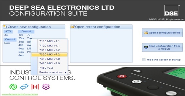
Before read and go further, we need to install DSE Configuration Suite software in order to set up information of the controllers base on our generator applications. You can download Deepsea software for free by click to this link: Deepsea controller software
Contents
- 1 Dse7320 configuration setup
- 1.1 DSE7320 configuration Module Setup
- 1.2 DSE7320 configuration Application
- 1.3 DSE7320 configuration Input
- 1.4 DSE7320 configuration Output
- 1.5 DSE7320 configuration Timer
- 1.6 DSE7320 configuration Generator
- 1.7 DSE7320 configuration Main Settings (DSE 8610 MKII not available)
- 1.8 DSE7320 configuration Engine
- 1.9 DSE7320 configuration Communication, connection (DSE 4520 MKII and DSE 6020 not available)
- 1.10 DSE7320 configuration Planning
- 1.11 DSE7320 configuration Configurable CAN engine (DSE 4520, 6020 not available)
- 1.12 DSE7320 configuration Alternative configurations
- 1.13 DSE7320 configuration Additional connections (DSE 4520, 6020 not available)
- 1.14 DSE7320 configuration Advanced (DSE 6020 not available)
- 2 Deep sea electronics 7320 wiring diagram & 8610, 6020, 6120, 4520
- 2.1 Basic Deep Sea wiring diagram
- 2.2 Detailed DSE wiring diagram
- 3 Operating the DSE controller (DSE 7320 MKII)
- 3.1 CATEGORY: DEEPSEA DOCUMENTS
Dse7320 configuration setup
We will start Dse7320 configuration TTTT from here:
- Module.
- Application.
- Input.
- Output result.
- Time.
- Generator.
- Main parts.
- Current main sections.
- Engine.
- Communicate.
- Schedule.
- Maintenance alarm.
- Algebraic configuration.
- Extend.
- Advanced.
DSE7320 configuration Module Setup
This section allows the user to change options related to the module itself.
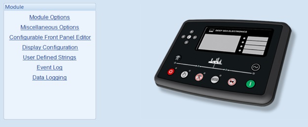
When setting up the Module we can install
User information (can be set as: job number, customer name, engineer name, …).
Install warning lights.
Add logo tags or insert text.
Slideshow: Displayed at startup, used for screensavers.
Select utility options for the system
Allows fast loading of features.
Gives scratch alert sound.
Reset all alarms.
Turn on sleep mode.
Turn on fuel manually control the pump.
Manually turn on the control frequency cutoff.
Support left-to-right and right-to-left languages. (Version 5.xx and up).
Enable alternate control interrupt buttons. (Version 6.xx or later).
Turn on cooldown in stop mode. (Version 9.xx and up).
Enables maintenance alarms. (Version 9.xx and up).
Turn on the backlight.
Displays active DTC.
DTC display not working.
Generator voltage display filter.
The filter shows the mains voltage.
Configurable status screen
Configurable status screens allow operators to design status screens to better suit user or application requirements. Here are the summary toolbars that are displayed when the system is active.
Automatic generator controller display.
Alternate configuration.
Engine.
Generator.
Main configuration.
Timer.
Planning.
Display configuration
Home page.
Configurable status screen.
Device blocking: Turn off the following device on the module display.
User-defined string
Event diary
The modular display option allows the operator to select the date or time.
The event log can be configured to allow the user to choose which events are stored.
Reference: DSE7320
Reference: DSE8610
DSE7320 configuration Application
Optional ECU (ECM)
Engine type: Choose the right motor type for your system.
Advanced J1939: The module will read the instrumentation from the engine ECU and display basic and advanced:
- Engine speed.
- Oil pressure.
- Engine coolant temperature.
- Now run.
- Engine oil temperature.
- Exhaust gas temperature.
- Fuel pressure.
- Total amount of fuel used.
- Fuel consumption.
- Inlet temperature.
- Coolant water pressure.
- Turbo pressure.
Alternating engine speed: Select if the motor runs at the alternate speed as configured by the motor manufacturer. Do not select if the motor runs at the rated speed configured by the manufacturer.
Modbus motor connection port of Deep Sea controller: RS485 port, DSENet port.
Double standard
Duplicate:
- Inactive: The module acts as a standalone module.
- Always active: The active module is the main module.
- On active input: Active module as a slave module.
Allowed Load Balancing: If no load balancing is selected, no load balancing will take place, the main controller pulls the load independently. If load balancing is selected to take place, based on the main controller controller balance time configuration, the motors will change at regular intervals.
Timing Load Balancing: The main controller will run during the load balancing period. After that time the master and slave controllers will work together. If there is no sub-controller, the main controller still works independently.
Automatic load sensor
When called to idling, if a load is detected, the module will force close the breaker (if connected) and will turn on the cooldown timer when the setup is required to stop. This is to ensure that the unit is cooled down before stopping after running with an unexpected load (in a manual shut-off system).
Cutting machine control
Enable alternate interrupt button control.
Allows manual interrupt button control.
Synchronization test.
Conversion closed.
Synchronization test
Low frequency.
Fox frequency.
Voltage.
Phase angle.
Enable active sync
AVR.
Cut speed.
No alarm sync
Action on activation.
Back to open switch.
Latency.
DSE7320 configuration Input
The input page is divided into smaller sections. Select the required part with the mouse.
Oil pressure
The sensor type can be selected.
Adjust the sensor workpath.
Turn the alarm on or off.
Turn warnings on and off.
Article triggering alarm parameters.
Cooling temperature
The sensor type can be selected.
Enables and disables alarms based on the set values.
Fuel level
Select the sensor type.
Toggle alarms based on setting values.
Adjust delay.
Select the alert type.
Send and save SMS logs.
Flexible sensor
Select the sensor type and adjust the name.
Select the required alert type.
Turn alerts on and off.
Adjust the alarm based on the set value.
Digital input
Set name and function with input.
Select the required alert type.
Turn alerts on and off.
Adjust delay.
DSE7320 configuration Output
Digital output
Supplied from the emergency stop input.
Select the output used for control.
Virtual LEDs
Allows you to adjust the configuration of the status to set up the warning LEDs.
DSE7320 configuration Timer
Start timer
Start delay:
- Load-on remote boot.
- Remote boot off load.
- Faulty power supply
- Start telemetry.
Start timing:
- Primary temporal delay.
- Attempts to interact.
- Join the rest.
- Rotation delay.
- Spinning crazy.
- The rest turns.
- Limit smoke.
- Limit secondhand smoke.
- Safe delay.
- The warming.
- ECU thread time.
- MPU failure delay.
Load/Stop Timer
Load timer:
- Delayed transfer/load time.
- Switching pulse.
- Pulse trip interrupt.
- Stop Timer:
- Return delay.
- Cooling.
- Cooling at idle.
- Hold power from ETS.
- Can’t stop the delay.
Module Timer
Interface timer:
- Page
- Roll.
- Backlight.
- Sleep timer.
DSE7320 configuration Generator
Generator selection
Generator equipment: Select if using a generator.
Choose the number of poles for the generator: 2, 4, 6, 8,,….
Choose the number of phases and wires for the generator.
Select the primary and secondary currents for the generator.
Generator phase rotation warning: Select if the generator is phase-shifted, it will issue a warning.
Generator breaker control: Turn on the breaker alarm:
- Can’t close.
- Synchronized.
- Can not open.
Generator specs:
- Rated active power (kW).
- Rated reactive power (KVAr).
- Power factor (cos φ).
Voltage selection
Pressure drop: Set an alarm when the voltage drops, there are two types of settings: pressure drop alarm and pressure drop warning, you can adjust the delay for the warning.
Active load voltage: Regulates the voltage for the active load and can trigger an alarm if the required voltage is not set.
Generator rated voltage: Adjust generator rated voltage.
Over-voltage: Set alarm when voltage increases, there are two types of settings: surge alarm and surge warning, can adjust the delay for the warning.
Generator frequency
Reduce frequency: Set an alarm when the frequency decreases, there are two types of settings: frequency reduction alarm and frequency reduction warning, can adjust the delay for the alarm.
Active load frequency: Adjusts the frequency for the active load and can trigger an alarm if the required frequency is not set.
Generator rated frequency: Adjust generator rated frequency.
Increase frequency: Set the alarm to have when the frequency increases, there are two types of settings: increase in frequency and increase in frequency, and you can adjust the delay for the alarm.
Remove frequency: When the frequency reaches the set value, the transmitter will turn off.
Frequency Option: Allows you to cross the frequency by how many % and for a short period of time.
Generator current
Generator current regulation: Adjust the primary current between the phases and the secondary current. Current position of current, full load current value and primary side current voltage.
Generator current warning:
Over-current warning: Turn on/off over-current notification and adjust over-current in certain time. Select the action associated with the alert.
Short circuit: Enable/disable short circuit notification and adjust circuit break current for a certain time. Select the action associated with the alert.
Phase out-of-order: Enable/disable phase-out-of-order notification and adjust phase out-of-order percentage and delay. Select the action associated with the alert.
Open Circuit Error: Enables/disables open circuit notification and allows open circuit by what percentage for a certain period of time. Select the action associated with the alert.
Generator capacity
Overload protection: Turn on/off the overload notification, adjust the voltage when the overload is reached, it will return to the normal voltage, or turn on the warning and action if the overload is over, can customize the overload delay .
Load control: Enable/disable load warning message, select load number and and adjust load auxiliary pulling power if the lowest and highest value is reached for better load pulling. The delay can be adjusted.
Load control: Turn on/off the payload announcement, select the number of loads and the number of loads that are connected enough to work. If the power reaches high or lower, the adjustment within the set time will close and disconnect the generator’s load bridge.
Reverse power: Turn on/off the reverse power notification, if the reverse power reaches the set power threshold within the set time period, an alarm and action will be taken.
Low load: Turn on / off low load notification, if the power is lower than the set capacity, it will be raised to the return power, if within the set time, it cannot be raised to the returned power, it will issue a warning and take action.
Reactive power (Var)
Active reactive power: Enable/disable early notification and active reactive power warning. When the active reactive power is set to the preset level, the early notification will reduce the active reactive power to the return level, if the active reactive power increases to the alarm level within the set time period, the alarm will be triggered. report and take action.
Negative reactive power: Enable/disable early notification and negative reactive power warning. When the negative reactive power is set to the preset level, the early notification will reduce the negative reactive power to the return level, if the negative reactive power increases to the alarm level within the set time period, the alarm will be triggered. report and take action.
DSE7320 configuration Main Settings (DSE 8610 MKII not available)
Main Settings
Select key settings information:
- Select the number of phases and wires for the main system.
- Select primary and secondary currents for the main system.
- Main system phase rotation warning: Selected if the system is phase-shifted, it will issue an alarm.
Main system breaker control: Turn on the breaker alarm:
- Can’t close.
- Synchronized.
- Can not open.
Main system parameters:
- Rated active power (kW).
- Rated reactive power (KVAr).
Main system warning
Pressure drop: Set warning when voltage drops, there are two types of settings: pressure drop alarm and pressure drop warning, you can adjust the delay for the warning.
Overvoltage: Set alarm when the voltage increases, there are two types of settings: surge alarm and surge warning, can adjust the delay for the warning.
Reduce frequency: Set an alarm when the frequency decreases, there are two types of settings: frequency reduction alarm and frequency reduction warning, can adjust the delay for the alarm.
Increase frequency: Set the alarm to have when the frequency increases, there are two types of settings: increase in frequency and increase in frequency, and you can adjust the delay for the alarm.
Main system current
Primary system current regulation: Adjust the primary current between the phases and the secondary current. Current position of current, full load current value and primary side current voltage.
Main system current warning:
- Over-current warning: Turn on/off over-current notification and adjust over-current in certain time. Select the action associated with the alert.
- Short circuit: Enable/disable short circuit notification and adjust circuit break current for a certain time. Select the action associated with the alert.
- Open Circuit Error: Enables/disables open circuit notification and allows open circuit by what percentage for a certain period of time. Select the action associated with the alert.
DSE7320 configuration Engine
Engine options
ECU options:
- Select the engine type.
- Advanced J1939: Enable/disable engine parameter display.
- Alternating engine speed: Select if the motor runs at the alternate speed as configured by the motor manufacturer. Do not select if the motor runs at the rated speed configured by the manufacturer.
- Modbus motor connection port: RS485 port, DSENet port.
- Adjust engine speed: Enable/disable motor speed regulation by DSE.
- Another choice
- On/off measuring device set J1939-75.
- Enable/disable measurement alarm J1939-75.
- Select the source address for CAN.
- Boot options: can start trial number of times.
- Initial water temperature: on/off adjusts water temperature, selects certain temperature and time.
- Water temperature later: turn on/off adjust water temperature, select certain temperature and time.
Optional ECU
For recording engine operating time.
Allows to reproduce tasks.
Enable speed conversion.
Set the periodic cooling time and display the quality of the coolant.
Set the delay of the ECU.
Attenuation: Adjusts the allowable attenuation of the coolant.
Adjust the SPN ignore list.
Set source address for CAN.
Warning of ECU
ECU fault alarm and action if alarm occurs.
DM signal:
- Amber ECU: Adjusts the delay, form, and action of the signal.
- Red ECU: Adjusts the delay, mode of operation and action of the signal.
- ECU malfunction: Adjusts delay, behavior pattern and signal action.
- ECU protection: Adjusts delay, behavior and signal action.
Input temperature: Enable/disable motor input alarm and early warning, If the temperature is higher than the early alarm temperature will be cooled and put into return temperature if set temperature alarm temperature will perform alarms and alert actions.
Other specific signals:
- DPTC Filter: Turn on/off and adjust the signal’s appearance and action.
- HEST active: Turns on/off and adjusts the active form and action of the signal.
- DEF level: Enables/disables and adjusts the delay, form and action of the signal.
- Inductive SCR: Turn on/off and adjust the delay, form and action of the signal.
Oil pressure:
- Enable/disable open circuit alarm sensor message.
- Low oil pressure alarm: After turning on the warning, it is possible to set up to adjust the early and alarm notifications according to the settings and enable the action to be used urgently if the alarm is enabled.
Coolant water temperature
Coolant temperature warning:
- Turn on/off the coolant temperature warning.
- Turn on/off the low coolant temperature early notification, if the coolant temperature drops below the low alarm setting, the return level will be adjusted.
- On/off early warning of high coolant temperature, warning and shutdown. If the coolant temperature rises above the early warning level, the return level will be adjusted, if the temperature continues to rise, the alarm system will warn and if the level rises to the stop level, the engine will stop.
Coolant temperature control:
- Coolant control: On/off adjusts the coolant temperature within the setting range.
- Coolant control: On/off adjusts coolant temperature within a set range.
- Fan control: Control the cooling time of the fan.
Fuel options
DEF level: On/off enables low early alarm and low alarm, adjustable low early alarm and low alarm level according to setting indicator, adjustable delay.
Gasoline engine options: Set a gasoline engine timer that adjusts throttle time, gas delay, and ignition off delay.
Break rate:
- Optionally disconnect on oil pressure and check oil pressure before starting.
- Adjust generator frequency and engine rotation speed.
- Adjust the oil pressure according to the Bar reading.
- Adjust on/off select generator charging and charging voltage options.
- Adjust generator voltage on/off.
- Turn on/off hold the button to record and limit the start of manual recording.
Speed sensor:
- ECM speed sensor on/off.
- Magnetic receiver on/off is equipped.
- Adjust the number of flywheel teeth.
- Enable/disable multiple attempts to join, choose the wrong number of attempts.
- Select action when sensor signal is lost.
- Turn on/off speed alarm if sensor is faulty.
- Select action when the circuit opens magnetically.
Speed settings:
- Low speed: Enable/disable early notification and warning when speed is low, if speed is lower than speed early notification will be accelerated and reverted back to speed if speed is lower than warning speed perform alarms and alert actions.
- High speed: Enable/disable early notification and warning when speed is high, if speed is higher than speed of early notification will be decelerated and returned to return speed if speed is higher than warning speed perform alarms and alert actions.
- Adjust the running speed of the motor.
- Speed options: Allows you to go through the speed by how many % and in a short time.
Factory battery:
- Voltage warning: When the voltage is low or higher than the set voltage, it will be returned to the return voltage within a set delay.
- Generator alarm charging: Turn on/off using the module to charge the generator, if the voltage drops to the set value, it will warn or stop the generator for the set time.
- Select the display engine icon.
DSE7320 configuration Communication, connection (DSE 4520 MKII and DSE 6020 not available)
Communication options, connection
Module Identity: Site Identity and Controller Identity.
RS232 Port
Select serial port configuration.
Install the module.
Set the initialization chain.
Connection settings:
- The main inactivity timeout.
- Connection time delay.
- Set the number of retries.
- Time delay retry.
- Delay cycle repetition time.
- Time delay between frames.
- Control the SMS module.
RS485 port
Set basic functions: dependent ID, baud rate and port usage.
Adjust the main inactivity timeout.
Connection adjusts delay between frames, stop bits, parity check.
Screen controller
Enable/disable display.
Select the connection port.
DSE7320 configuration Planning
Planning Settings
Enable/disable the planner.
Adjust the plans made on the two tables bank1 and bank2.
Maintenance alarm
Enable/disable maintenance notifications and set the name, alarm type, alarm time, alarm on due date and select time on 3 maintenance alarms.
DSE7320 configuration Configurable CAN engine (DSE 4520, 6020 not available)
Received the measuring device
Can install:
- Activated.
- Opinion.
- Description.
- Bits.
- CAN ID.
- Enable/disable timeout.
- Data structure.
- Display.
- Bus value.
- Mapped value.
Instrument transmission
Can install:
- Activated.
- Bits
- CAN ID.
- Rate (ms).
- Bytes.
- Bits.
- Longs.
- Register.
- Source value.
- Bus value.
DSE7320 configuration Alternative configurations
Optional alternative configurations
Select default configuration.
Name the default profile.
Configuration
Configuration Options: Enable/disable the profile and give it a name. Disconnect/block main system voltage/generator meter.
Generator options:
- Voltage options.
- Frequency options.
- Current option.
- Capacity options.
- Optional reactive power (VAr).
Main system options:
- System Preferences.
- Alert options.
- Current option.
Engine options:
- Engine options.
- Speed options.
DSE7320 configuration Additional connections (DSE 4520, 6020 not available)
( 2130, 2131, 2133) input module and 2152 output module
Equivalent input configuration.
Equivalent input
Digital input.
2157 relay module
Enable/disable the extension feature.
Forward input (normally open).
Output forward (switch).
Display Module 2510/2520 MKII
Turn on/off the display module.
Turn on/off control buttons.
Sound configuration:
- Turn on/off the sound.
- By main unit.
- Turn on/off the auto off timer and adjust the auto off time.
2548 communication module
Enable/disable communication module.
Sound configuration.
LED indicator.
Battery charger
Turn on/off the battery charger:
- Alarm action link lost.
- Modbus ID.
- Display instrumentation.
- Name the charger.
Charger off alarm:
- Enable/disable charger off alarm.
- Module action.
- Alarm chain.
Charger warning alarm:
- Enable/disable charger warning alarm.
- Module action.
- Alarm chain.
DSE7320 configuration Advanced (DSE 6020 not available)
Advance setting
Guard:
- Enable/disable protection mode.
- Protections are disabled.
- Security has turned off the alarm action.
- Override coolant level protection.
Exit mode:
- Enable/all exit mode.
- Install works.
- Period.
Timer Synchronization:
- Sync delay.
- Interlock override off.
AVR options:
- Enable/disable AVR CAN communication.
- AVR source address.
- CAN module address.
- Match the AVR alternate configuration to the controller.
AVR date failed:
- Action settings,
- Equip weapons.
- Activation delay.
Error AVR:
- Action settings,
- Equip weapons.
- Activation delay.
PLC settings
Allows connection/installation of PLC with DSE.
Additional settings pages
Additional settings pages for DSE include: Page 166, 167, 168, 169.
Deep sea electronics 7320 wiring diagram & 8610, 6020, 6120, 4520
Basic Deep Sea wiring diagram
It is important to install the DSE 7320 MKII on the generator. The filling must follow the scheme as follows:
- Pins 1-2: DC 8 – 35V SUPPLY.
- Pin 3: EMERGENCY STOP.
- Pins 4-5: FUEL & OUTPUT BANK (Flexible with CAN).
- Pin 6: CHARGE GENERATOR.
- Pin 7: EARTH.
- Pins 8-13: DC OUTPUT.
- Pins 15-19: ANALYSIS INPUT.
- Pins 22-30: ELECTRONIC MOTOR & MAGIC TERMS.
- Pins 39-40: OUTPUT NORMAL CLOSE CONTACT.
- Pins 41-42: NORMAL POINT OPENED.
- Pins 43-46: GENERATOR SENSOR.
- Pins 47-50: MAIN SENSOR (UTILITY).
- Pins 51-55: GENERATOR/ CURRENT LOAD.
- Pins 60-67: Configurable INPUT
- RS232.
- RS485.
- USB.
Deep sea electronics 7320 wiring diagram:
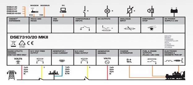
Deep sea electronics 4520 wiring diagram:
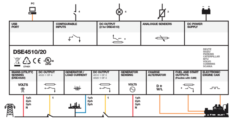
Deep sea electronics 6020 wiring diagram:
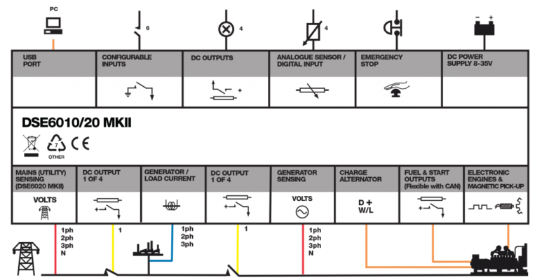
Deep sea electronics 8610 wiring diagram:
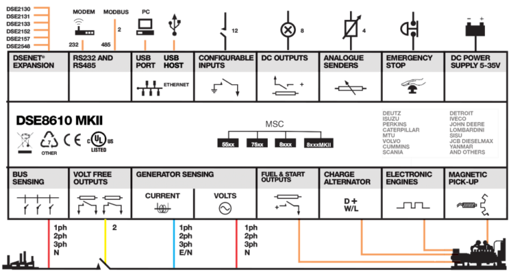
Detailed DSE wiring diagram
DSE7320 wiring diagram in detail
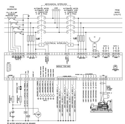
DSE4520 wiring diagram in detail
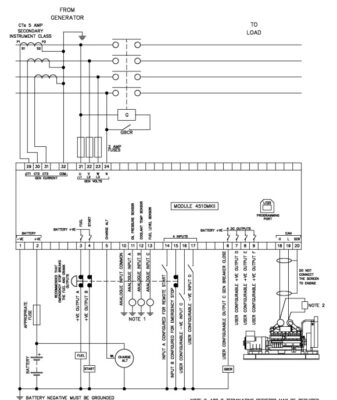
Please click on the link to get full information about DSE4520
DSE6020 wiring diagram in detail
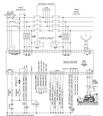
Please click on the link to get full information about DSE6020
DSE6120 wiring diagram in detail
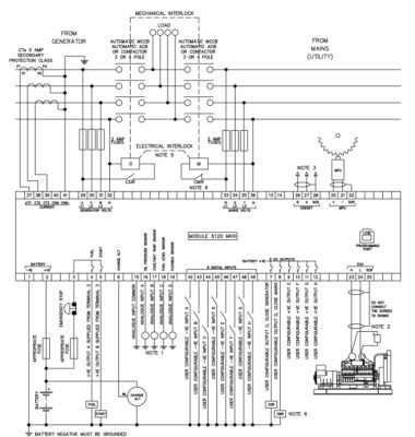
Please click on the link to get full information about DSE6120
DSE8610 wiring diagram in detail
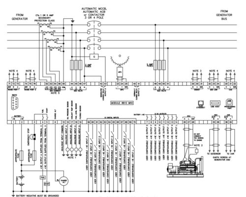
Operating the DSE controller (DSE 7320 MKII)
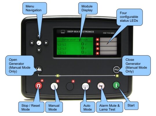
After setting parameters and filling on the generator, the next thing is to operate the machine. Operation is the last step to put into use. The steps are as follows:
Check fuel.
Check the coolant level.
Check the battery.
Check the air filter.
Turn on the DEEPSEA power switch.
Stats check based on buttons: Left, right, up, down.
Start generator:
Manual start:
Step 1: Select the manual start button.
Step 2: Select start the machine.
Step 3: Check the parameters to know.
Step 4: Select the button to stop the machine if not in use.
Auto start:
Step 1: Select Auto, the machine will automatically operate.
Step 2: Check the parameters to know.
Note: When choosing Auto, it will not interfere with the system by the controller anymore, so it is often used when the mains power is out. When there is power to the grid and the generator is in Auto mode, the generator will automatically turn off.
Please contact us for DSE7320 maintenance alarm reset and troubleshooting
TTTT GLOBAL co Ltd,.
Address: Landmark 4 Building, Vinhomes Central Park, 720A Dien Bien Phu Str, Ward 22, Binh Thanh District, Ho Chi Minh City, Vietnam.
Website: https://ttttglobal.com/en/
Hotline: +84286 2728 334
Email: Info@ttttglobal.com
CATEGORY: DEEPSEA DOCUMENTS
RELATED POSTS
Панель управления DSE6020 является универсальный контроллером для работы на дизельных, бензиновых и газовых электростанциях. Данная панель управления позволяет следить за состоянием электростанции, запускать генераторную установку в автоматическом режиме, обеспечить удаленный мониторинг посредством различных вариантов коммуникаций. Панель DSE6020 оборудована встроенным детектором фаз, имеет USB разъём для подключения периферийного оборудования и PC компьютера.
Панель управления DSE6020 контролирует скорость двигателя, частоту напряжения, силу тока, давление масла, температуру ОЖ и уровень топлива, выводит аварийные ошибки и предупреждения на монитор и ЛЕД-индикаторы.
DSE6020 имеет CAN-соединение с блоком управления двигателем. Так же есть вход для подключения датчика PICK-UP и электронного регулятора оборотов. Панель DSE6020 можно легко настроить под различные условия эксплуатации с помощью оригинального программного обеспечения DSE Configuration Suite. Так же имеется возможность настройки параметров с передней панели без применения оригинального программного обеспечения.
Возможности:
- LCD-дисплей с подсветкой
- аварийные сигналы выводимые на LCD-дисплей и ЛЕД-индикаторы
- энергонезависимая память
- подключение CAN-шины и датчика скорости
- настройка панели с помощью оригинального программного обеспечения DSE Configuration Suite
- настраиваемые параметры и задержки
- возможность настройки альтернативной конфигурации
- журнал ошибок
- возможность запуска оборудования по удаленному сигналу
- контроль выходного напряжения
- контроль мощности (кВт, кВА, кВар)
- контроль за внешней сетью для автоматического запуска электростанции
- кнопка «Тест»
- контроль за напряжение аккумуляторной батареи
- управление подогревателем двигателя
- счетчик моточасов
Преимущества:
- управление сетевыми и генераторными контакторами щита АВР
- счетчик моточасов позволяет контролировать общую наработку генераторной установки и двигателя
- дружественный интерфейс для оператора позволяет отслеживать сразу несколько параметров электростанции
- модуль DSE6020 может быть настроен под индивидуальные требования и особенности оборудования
- корпус IP65
Для покупки товара в нашем интернет-магазине выберите понравившийся товар и добавьте его в корзину. Далее перейдите в Корзину и нажмите на «Оформить заказ» или «Быстрый заказ».
Когда оформляете быстрый заказ, напишите ФИО, телефон и e-mail. Вам перезвонит менеджер и уточнит условия заказа. По результатам разговора вам придет подтверждение оформления товара на почту или через СМС. Теперь останется только ждать доставки и радоваться новой покупке.
Оформление заказа в стандартном режиме выглядит следующим образом. Заполняете полностью форму по последовательным этапам: адрес, способ доставки, оплаты, данные о себе. Советуем в комментарии к заказу написать информацию, которая поможет курьеру вас найти. Нажмите кнопку «Оформить заказ».
- Page 1
DSE 6020 AMF DSE 6020 AMF KONTROL MODÜLÜ CONTROL MODULE ÇALIŞTIRMA EL KİTABI OPERATING MANUAL DSE 6020 AMF… - Page 2
6020 AUTO DSE 6020 AMF KONTROL MODÜLÜ ÇALIŞTIRMA EL KİTABI ÜRETİCİ FİRMA YETKİLİ SERVİS AKSA JENERATÖR SANAYİ A.Ş. AKSA SERVİS & KİRALAMA Gülbahar Caddesi 1. Sokak Muratbey Beldesi, Güney Girişi Caddesi No:8 34212 No: 2 Güneşli / İSTANBUL 34540 Çatalca / İSTANBUL… -
Page 4: Table Of Contents
KONTROL BUTONLARININ İŞLEVİ ………………. 1 KONTROL BUTONLARI………………….2 MOTORUN ÇALIŞTIRILMASI ………………..3 MOTORU DURDURMA ………………….3 OPERASYON ……………………..4 5.1. OTOMATIK OPERASYON……………………..4 5.2. MANÜEL OPERASYON……………………….5 5.3. TEST OPERASYON…………………………6 MODÜL EKRANI ……………………6 6.1. ÖLÇÜ ALETLERI…………………………. 7 6.2. OLAY GÜNLÜĞÜ…………………………7 KONUM İKONLARI……………………
-
Page 5: Kontrol Butonlarinin İşlevi̇
1. KONTROL BUTONLARININ İŞLEVİ Genel durum gösterge ekranı Ortak Alarm Göstergesi Ekran ilerletme butonu 6020 Sayfa butonu Motoru başlatma (manuel konumunda) Stop konumu AUTO Alarm sus / lamba test Manüel konumu Yükte test konumu Otomatik konumu 6020 AUTO Şebeke hazır LED. Jeneratör hazır LED Şebeke devrede LED.
-
Page 6: Kontrol Butonlari
2. KONTROL BUTONLARI Stop / Reset konumu Bu buton, modülü Stop / Reset konumuna getirir. Herhangi bir alarm durumuna sebep olan kriteri ortadan kaldırmak için bu butona basarak sıfırlama yapılır. Eğer motor çalışıyorsa ve modül Stop pozisyonuna alınırsa, modül jeneratörü otomatik olarak yüksüz duruma alır (transfer panosunda jeneratör anahtarını devre dışı bırakır).
-
Page 7: Motorun Çaliştirilmasi
3. MOTORUN ÇALIŞTIRILMASI 6020 Sonra start tuşuna basarak Önce manuel motoru marşlayın konumunu seçin AUTO NOT: Detaylı bilgi için bu manüelin ‘OPERASYON’ bölümüne bakınız. 4. MOTORUN DURDURMA 6020 Stop konumuna aldığınızda jeneratör durur AUTO NOT: Detaylı bilgi için bu manüelin ‘OPERASYON’ bölümüne bakınız.
-
Page 8: Operasyon
5. OPERASYON 5.1. OTOMATİK OPERASYON Otomatik konumun etkin olması için butonuna basınız. Alarm durumu yoksa ekranda Otomatik çalışma ikonu gösterilir. Otomatik konum, kullanıcının müdahalesine ihtiyaç duyulmadan jeneratörün start ve stop edilmesi, tam otomatik olarak çalışmasına olanak sağlar. 5.1.1. OTOMATİK KONUMDA BEKLEME Jeneratörü…
-
Page 9: Manüel Operasyon
5.1.4. DURDURMA SIRASI Şebeke voltajı ve frekansı, modül programında ayarlanan sınır değerlere döndüğünde, veya uzak start talebi kalktığında geri dönüş zaman sayıcı çalışır, sürenin sonunda yük jeneratörden şebeke beslemesine transfer edilir ve jeneratör soğutma zaman sayıcısı çalışır. Soğutma zamanı süresince jeneratör yüksüz çalıştırılıp yeterli soğutmayı yapmasına izin verilir., Soğutma durumu özellikle turbo-şarjlı…
-
Page 10: Test Operasyon
• stop butonuna basıldığında – jeneratör hemen stop edecektir. • Otomatik butonuna basıldığında, jeneratör, otomatik konum durdurma işlemini sıraya koymadan önce tüm AUTO otomatik konum start sinyalleri ve stop zamanlayıcıların işleyip işlemediğine bakacaktır. 5.3. TEST OPERASYONU butonuna basıldığında test konumu etkin olur. Butonun arkasında bulunan LED lambası yanarak bu hareketi doğrular.
-
Page 11: Ölçü Aletleri
ÖRNEK EKRAN Bu örnekte jeneratör voltajı Jeneratör sembolü tarafından gösterilir. Ölçü aleti Ölçü aleti ikonu Birimi Etkin yapılandırma Konum ikonu 6.1. ÖLÇÜ ALETLERİNİN GÖRÜNTÜLENMES Ekran aktif hale gelirken önce yazılım versiyonu ekrana gelecek daha sonra Jeneratör Frekansını gösterecektir. İlerletme butonuna tekrar basarak farklı bilgi sayfalarını LCD ekranına getirmek mümkündür Bilgi butonuna basarak ölçü…
-
Page 12: Konum İkonlari
7. KONUM İKONLARI Ünitenin hangi konumda olduğu ekranda ikon ile gösterilir. İkon Grafik Detaylar Ünite stop konumunda ve motor çalışmıyorken bu ikon Durmuş / Kapalı ekranda görünür. Ünite otomatik konumunda ve motor çalışmıyorken bu ikon Otomatik ekranda görünür. Ünite manüel konumunda ve motor çalışmıyorken bu ikon Manüel ekranda görünür Bir zamanlayıcı…
-
Page 13: Korumalar
8. KORUMALAR Bir alarm durumu meydana geldiğinde ortak alarm LED i yanacaktır. LCD ekran ‘Bilgi sayfası’ dan ‘Alarm Sayfası’ na atlayacaktır. LCD ekranda birçok alarm örneğin “ Yüksek Motor Sıcaklığı durdurma”, “ Acil Stop” gösterilecektir. Bu alarmlar meydana geldiğinde sırayla ekranda otomatik olarak gösterilecektir. Bir ikaz alarm olduğunda ilgili ikon ekranda gösterilecektir.
-
Page 14: Durdurma Alarmlari
8.2. DURDURMA ALARMLARI Durdurma alarmları jeneratörü durdurur ve alarmlar kilitlenir. Alarm durumu ortadan kaldırıldıktan sonra Stop/Sıfırlama butonuna basılarak modül sıfırlanır. NOT: — Alarm durumu ortadan kaldırılmadıysa modülde alarm durumu sıfırlanmaz. E k r a n Sebebi Modül CAN çalışması için yapılandırılmışsa ve motor Can veri CAN ECU Veri Hatası…
-
Page 15: Kablolama
9. KABLOLAMA…
- Page 16
6020 AUTO DSE 6020 AMF CONTROL MODULE OPERATING MANUAL HEAD OFFICE AUTHORIZED SERVICE AKSA JENERATÖR SANAYİ A.Ş. AKSA SERVICE & RENTAL Gülbahar Caddesi 1. Sokak Muratbey Beldesi, Güney Girişi Caddesi No:8 34212 No: 2 Güneşli / İSTANBUL 34540 Çatalca / İSTANBUL… - Page 18
DESCRIPTION OF CONTROLS ………………1 CONTROLS……………………..2 STARTING THE ENGINE ………………… 3 STOPPING THE ENGINE…………………. 3 OPERATION……………………..4 5.1. OTOMATIC OPERATION ……………………..4 5.2. MANUAL OPERATION ……………………… 5 5.3. TEST OPERATION ………………………… 6 MODULE DISPLAY ……………………. 7 6.1. VIEWING THE INSTRUMENTS ……………………7 6.2. -
Page 19: Description Of Controls
1. DESCRIPTION OF CONTROLS Main status display Common alarm indicator Display scroll button 6020 Page Button (information) Start engine Select stop mode AUTO Alarm mute / lamp test Select manual mode Select test mode Select auto mode 6020 AUTO Generator Available Mains available Mains on load Generator on load…
-
Page 20: Controls
2. CONTROLS Stop / Reset This button places the module into its Stop/Reset mode. This will clear any alarm conditions for which the triggering criteria have been removed. If the engine is running and the module is in Stop mode, the module will automatically instruct the changeover device to unload the generator.
-
Page 21: Starting The Engine
3. STARTING THE ENGINE 6020 …Then, press the Start First select Manual button to crank the engine mode AUTO NOTE:- For further details, see the section entitled ‘OPERATION’ elsewhere in this manual. 4. STOPPING THE ENGINE 6020 Select Stop/Reset mode. The generator stops.
-
Page 22: Operation
5. OPERATION 5.1. AUTOMATIC OPERATION This mode is activated by pressing the pushbutton. The icon is displayed to indicate Auto Mode operation if no alarms are present. Auto mode will allow the generator to operate fully automatically, starting and stopping as required with no user intervention.
-
Page 23: Manual Operation
NOTE: The Load transfer signal remains inactive until the oil pressure has risen .This prevents excessive wear on the engine . If all start requests are removed, the stopping sequence will begin. 5.1.4. STOPPING SEQUENCE On the return of the mains supply, (or removal of the Remote Start signal if the set was started by remote signal), the return delay timer is initiated, once it has timed out, the load is transferred back to the mains (utility).
-
Page 24: Test Operation
Once the load has been transferred to the generator, it will not be automatically removed. To manually transfer the load back to the mains. • Press the auto mode button to return to automatic mode. The set will observe all auto mode start AUTO requests and stopping timers before beginning the Auto mode stopping sequence.
-
Page 25: Module Display
6. MODULE DISPLAY BACKLIGHT The backlight will be on if the unit has sufficient voltage on the power connection while the unit is turned on, unless the unit is in Power Save mode, or if the engine is cranking for which the backlight will be turned off. GRAPHICAL DISPLAY — 4- line, 64 x 132 small Graphic Display with LED Backlight — Icon and numeric display.
-
Page 26: Event Log
Metering: Generator Voltage, 3-phase, L-L and L-N Generator Frequency Generator Current Mains Voltage, 3-phase, L-L and L-N Battery Voltage Engine hours Run Oil Pressure Gauge Engine Temperature Gauge Fuel Level 6.2. EVENT LOG The info button toggles between the display of the instrumentation and the event log. Pressing the down button will move to the previous event, the event log entry at position 1 being the most recent.
-
Page 27: Auto Run Icon
7.1. AUTO RUN ICON When the engine is running in AUTO mode, an icon is displayed to indicate the reason for the set being run. Auto run reason Icon Remote start input Low battery run Scheduled run Mains failure 7.2. INSTRUMENTATION ICONS When displaying instrumentation a small icon is displayed in the instrumentation icon area to indicate what value is currently being displayed.
-
Page 28: Protections
8. PROTECTIONS When an alarm is present, the Common alarm LED will illuminate. The LCD display will jump from the ‘Information page’ to display the Alarm Page. See section entitled Graphical Display for details of alarm icons. The LCD will display multiple alarms E.g. “High Engine Temperature shutdown”, “Emergency Stop” and “Low Coolant Warning”.
-
Page 29: Shutdown Alarms
8.2. SHUTDOWN ALARMS Shutdowns are latching alarms and stop the Generator. Clear the alarm and remove the fault then press Stop/Reset to reset the module. NOTE:- The alarm condition must be rectified before a reset will take place. If the alarm condition remains, it will not be possible to reset the unit (The exception to this is the Low Oil Pressure alarm and similar ‘delayed alarms’, as the oil pressure will be low with the engine at rest).
-
Page 30: Amf Control Modul Wiring
9. 6020 AMF CONTROL MODUL WIRING…
- Page 32
İSTANBUL AVRUPA YAKASI AVCILAR MUSTAFA KEMAL PAŞA MAH. YILDIRIM BEYAZIT CAD. DEMET SOK. NO:132 AVCILAR/İSTANBUL T:0 212 428 66 66 PBX F:0 212 423 22 22 BAĞCILAR ORTAK BÖLGE (GÖKSU) FATİH, ZEYTİNBURNU, GAZİOSMANPAŞA, EYÜP MERKEZ MAH. ATATÜRK CAD. NO:24 YENİBOSNA T:0212 630 79 80/0212 630 79 98 KAĞITHANE ÇAĞLAYAN MAH. - Page 33
ALGERIA CHINA IRAQ Aksa Algeria Aksa Power Generation Aksa Power Generation (Iraq) Chemin du Parc d’Attraction (Changzhou) Co. Ltd. English Village House Cooperative El Baraka No: 417 Tixerain No.19 Tongjiang Road, New District, No:353 Arbil / Iraq Bir Moruad Rais / Alger… - Page 34
+ 971 4 880 9140 + 971 4 880 91 41 Ç‹N / CHINA No.19 Tongjiang Road, New District, Changzhou Jiansu Zone / China : + 86 (0) 519 856 01 307 : + 86 (0) 519 851 50 132 e-mail: aksa@aksapowergen.com…