

Argus Technologies Ltd.
018-570-C0 Rev B WC
Printed in Canada. © 2005 Argus Technologies Ltd. ARGUS and CORDEX are trademarks of Argus Technologies Ltd. All Rights Reserved.
Page 1 of 14
1 Introduction
1.1
Scope of the Manual
This instruction manual explains the installation and interconnection of the Cordex System Controller (CXC)
125/220Vdc panel (CXCP) and rack (CXCR) models from Argus Technologies.
NOTE: To aid the user with installation, frequent reference is made to drawings located at the rear of this manual.
1.2 Product
Overview
The CXC 125/220Vdc is an advanced system controller designed by Argus for operation with 125/220Vdc power
systems.
The CXCP and CXCR models each provide four digital and nine analog inputs that may be used to monitor a
wide range of power system components.
The CXCP and CXCR models allow the user to configure, monitor and control the entire DC power system from a
touch screen display similar to that used in a Personal Digital Assistant (PDA). Other features include temperature
compensation, auto equalization, remote access, dial out on alarm, battery diagnostics, as well as Web server
and SNMP support for configuration and monitoring.
NOTE: Separate documentation will be provided detailing the CXC software features, setup and operation.
The CXC offers additional advanced features via add-on “list options.” The customer should include these list
options at the time of ordering.
1.3
Part Numbers and List Options
Refer to the specifications section at the front of this manual for part numbers and ordering options.
Figure 1–Front view of Cordex controller 19” rack model CXCR
Latch (2PL)
Touch Screen
Reset Button
RS-232 (Craft Port)
LEDs
15 лет стабильной работы
Надежный поставщик электростанций, ИБП, стабилизаторов, АКБ и другого оборудования

Опытные инженеры
Проектирование, инжиниринг, монтаж, сервис

Собственный
производственно-складской комплекс
Более 17 000 выполненных проектов по всей РФ и СНГ
Готовые отраслевые решения
Строительство, Нефтегаз, Дата-центры ЦОД, Медицина, Торговые и Бизнес центры, Производство, Энергетика, ЖКХ
Лучшие цены и условия!
Скидки прорабам, дилерам и постоянным клиентам

ДГУ GeneralPower
Бесперебойное электроснабжение по разумной цене!

ИБП MAKELSAN
Инновационные и надежные решения!
Новейшие технологии, удобное управление, высокое качество продукции.
ИБП ИМПУЛЬС
Надежность, отказоустойчивость, высококлассная защита оборудования.

Cordex Controller Software Manual, Version 3.1x
User Manual
Part # 0700015-J0
Effective: 04/2012
member of The Group
™
Your Power Solutions Partner


Cordex Controller Software Manual
Version 3.1x
This software is compatible with Expanded Memory CXC
Controllers only.
NOTE:
Photographs contained in this manual are for illustrative purposes only. These photographs
may not match your installation.
NOTE:
Operator is cautioned to review the drawings and illustrations contained in this manual before
proceeding. If there are questions regarding the safe operation of this powering system, contact Alpha Technologies or your nearest Alpha representative.
NOTE:
Alpha shall not be held liable for any damage or injury involving its enclosures, power supplies,
generators, batteries, or other hardware if used or operated in any manner or subject to any
condition not consistent with its intended purpose, or is installed or operated in an unapproved
manner, or improperly maintained.
For technical support, contact Alpha Technologies:
Canada and USA: 1-888-462-7487
International: +1-604-436-5547
Email: support@alpha.ca
Copyright
Copyright © 2012 Alpha Technologies Ltd. All rights reserved. Alpha is a registered trademark of Alpha
Technologies.
No part of this documentation shall be reproduced, stored in a retrieval system, translated, transcribed, or
transmitted in any form or by any means manual, electric, electronic, electromechanical, chemical, optical, or
otherwise without prior explicit written permission from Alpha Technologies.
This documentation, the software it describes, and the information and know-how they contain constitute the
proprietary, confidential and valuable trade secret information of Alpha Technologies, and may not be used for
any unauthorized purpose, or disclosed to others without the prior written permission of Alpha Technologies.
The material contained in this document is for information only and is subject to change without notice.
While reasonable efforts have been made in the preparation of this document to assure its accuracy, Alpha
Technologies assumes no liability resulting from errors or omissions in this document, or from the use of the
information contained herein. Alpha Technologies reserves the right to make changes in the product design
without reservation and without notification to its users.

Contents
1. Introduction ……………………………………………………………………………………………………… 6
1.1 Scope of the Manual ………………………………………………………………………………………….6
1.2 Software Overview …………………………………………………………………………………………….6
2. Standard Features ……………………………………………………………………………………………. 7
2.1 Password Security …………………………………………………………………………………………….7
2.2 Software Conguration Loading and Updates ……………………………………………………….7
2.3 Customizable User Interface ……………………………………………………………………………….7
2.4 Mixed Rectier System ………………………………………………………………………………………8
2.5 Safe Voltage ……………………………………………………………………………………………………..8
2.6 Power Save ………………………………………………………………………………………………………8
2.7 Auto DC Priority …………………………………………………………………………………………………8
2.8 Battery Temperature Compensation …………………………………………………………………….8
2.9 Battery Auto Equalization ……………………………………………………………………………………9
2.10 Battery Monitor and Charge Current Control ……………………………………………………..10
2.11 Battery Test Scheduler ……………………………………………………………………………………10
2.12 Low Voltage Disconnect Operation …………………………………………………………………..10
2.13 Signals Management ……………………………………………………………………………………..10
2.14 Statistics and Historical Data ………………………………………………………………………….. 11
3. User Interface Options …………………………………………………………………………………….. 13
3.1 LCD Graphical User Interface ……………………………………………………………………………14
3.2 Home Screen (Default Operating Screen) …………………………………………………………..14
3.3 Contrast Adjustment of the GUI …………………………………………………………………………14
3.4 Menu Navigation - LCD …………………………………………………………………………………….15
4. Operation using the LCD GUI …………………………………………………………………………… 19
4.1 Start-up ………………………………………………………………………………………………………….19
4.2 Language Selection …………………………………………………………………………………………19
4.3 Date and Time …………………………………………………………………………………………………20
4.4 Resetting and Powering Down …………………………………………………………………………..20
2
0700015-J0 Rev B

4.5 Alarm Display and Conguration ………………………………………………………………………..21
4.6 Signals Display ………………………………………………………………………………………………..22
4.7 Rectiers (and Converters) Information ………………………………………………………………24
4.8 Voltage Mode Status and Temp Comp Settings ……………………………………………………25
4.9 Float (FL) Mode ……………………………………………………………………………………………….26
4.10 Equalize (EQ) Mode ……………………………………………………………………………………….26
4.11 Boost (BST) Mode ………………………………………………………………………………………….26
4.12 Battery Discharge Test or Battery Test (BT) Mode ………………………………………………26
4.13 Communications ……………………………………………………………………………………………28
5. Operating with the Web and Panel PC Interface …………………………………………………. 29
5.1 Communication Settings …………………………………………………………………………………..29
5.2 Getting Started ………………………………………………………………………………………………..30
5.3 Login ……………………………………………………………………………………………………………..31
5.4 Language Selection …………………………………………………………………………………………31
5.5 Saving Changes ………………………………………………………………………………………………31
5.6 Date & Time ……………………………………………………………………………………………………32
5.7 Alarm Display and Conguration ………………………………………………………………………..32
5.8 Converters ………………………………………………………………………………………………………33
5.9 Rectiers ………………………………………………………………………………………………………..33
5.10 Inverters ……………………………………………………………………………………………………….33
5.11 Battery Mode and Temp Comp Settings …………………………………………………………….33
5.13 Saving Conguration Files ………………………………………………………………………………34
5.12 Resetting the CXCU Controller ………………………………………………………………………..34
5.14 Summary of Menu Navigation ………………………………………………………………………….35
6. System Conguration: Programming and Adjustments ………………………………………… 36
6.1 System Info …………………………………………………………………………………………………….36
6.2 Converters ………………………………………………………………………………………………………39
6.3 Rectiers ………………………………………………………………………………………………………..39
6.4 Inverters …………………………………………………………………………………………………………43
6.5 Batteries …………………………………………………………………………………………………………50
6.6 Alarms ……………………………………………………………………………………………………………57
0700015-J0 Rev B
3

6.7 Signals …………………………………………………………………………………………………………..70
6.8 Controls ………………………………………………………………………………………………………….89
6.9 Communications ……………………………………………………………………………………………..91
6.10 Hardware ………………………………………………………………………………………………………93
6.11 Logs & Files (Web Interface only) …………………………………………………………………….94
6.12 Supervisor …………………………………………………………………………………………………….96
7. Advanced Programming…………………………………………………………………………………… 98
7.1 Example: Customize ………………………………………………………………………………………..98
7.2 Equation Builder Keypads …………………………………………………………………………………98
7.3 Tips on Programming ……………………………………………………………………………………….99
8. CXC Communications Menu Parameters …………………………………………………………. 100
8.1 Ethernet Port Conguration ……………………………………………………………………………..100
8.2 PPP Connection Devices ………………………………………………………………………………..101
8.3 Rear Port Conguration ………………………………………………………………………………….102
9. Remote Communications……………………………………………………………………………….. 104
9.1 Establishing a Network Connection via a Crossover Cable ………………………………….104
9.2 PPP Serial Data Connection ……………………………………………………………………………105
9.3 Modem Connection ……………………………………………………………………………………….. 111
10. Simple Network Management Protocol (SNMP) ………………………………………………..113
10.1 Overview …………………………………………………………………………………………………….113
10.2 Network Manager MIB Files ………………………………………………………………………….. 11 5
10.3 Communication Conguration ……………………………………………………………………….. 11 6
11. Factory Ranges and Defaults ………………………………………………………………………… 120
12. Modbus® Communications Protocol ……………………………………………………………… 131
13. Trouble-shooting …………………………………………………………………………………………. 139
14. Alpha Conventions ………………………………………………………………………………………. 140
14.1 Acronyms and Denitions ………………………………………………………………………………140
4
0700015-J0 Rev B

List of Tables
Table A — Web Interface Menu Structure …………………………………………………………………………….37
Table B — Output channel assignments ………………………………………………………………………………60
Table C — Digital input channel assignments……………………………………………………………………….61
Table D — Analog input channel assignments………………………………………………………………………70
Table E — Controller signal default denitions ……………………………………………………………………..72
Table F — Rectiers menu defaults …………………………………………………………………………………..120
Table G — Converters menu defaults ………………………………………………………………………………..120
Table H — Batteries menu defaults …………………………………………………………………………………..121
Table I — Alarms menu defaults ……………………………………………………………………………………….122
Table J — Controls menu defaults …………………………………………………………………………………….123
Table K — Communications menu defaults ………………………………………………………………………..124
Table L — Hardware menu defaults …………………………………………………………………………………..124
Table M — Supervisor menu defaults ………………………………………………………………………………..124
Table N — Signals menu defaults ……………………………………………………………………………………..124
Table O — Inverter Global Settings …………………………………………………………………………………..125
Table P — Inverter Parameters …………………………………………………………………………………………126
Table Q — Inverter Alarm Settings…………………………………………………………………………………….130
Table R — Table N–CXC Modbus PDU address denition for function code 0x01 (read coils) …..131
Table S — CXC Modbus PDU address denition for function code 0x02 (read discrete inputs) …132
Table T — CXC Modbus PDU address denition for function code 0x03 (read holding registers) 136
Table U — CXC Modbus PDU address denition for function code 0x04 (read input registers) …138
Table V — Trouble-shooting guide …………………………………………………………………………………….139
0700015-J0 Rev B
5

1. Introduction
1.1 Scope of the Manual
This document describes the software features, on-site setup, and operation of the Cordex System Controller (CXC) from Alpha Technologies. A basic understanding of Ethernet, TCP/IP, SNMP, RS-485, and
CAN bus functionality is required.
Refer to the Installation manual for hardware details.
1.2 Software Overview
The CXC software enables control of an entire DC + AC power system via the CXC central touch screen
user interface or web based monitoring and control interface. The software also allows the user to control
temperature compensation, auto equalization, remote access, and battery diagnostics.
The CXC is an integrated Alpha Cordex Controller designed to provide universal control for Alpha Group
products.
The CXC has Ethernet capability that supports a web interface and SNMP for customer access to the
equipment it is monitoring.
The CXC also has a CAN bus for communication with the Cordex rectifiers and other peripheral equipment.
1. 2.1 User Interface (UI)
Version 3.1x of the software is compatible with Expanded Memory CXC Controllers only. For each controller, a user can use either a touch screen or a web interface to set up and manage the system.
Remote communications over the web interface can be established with the step-by-step connection
wizard available from the Alpha website (www.alpha.ca.ca) or refer to Chapter “9. Remote Communications” on page 104 for detailed instructions.
1. 2.1.1 LED lights
Each CXC has three LEDs located on the front panel. These LEDs are used to display the alarm status of
the power system, CXC progress and status during startup, and file transfers.
1.2.1.2 Alarm conditions
When an alarm occurs, an LED illuminates corresponding to the following system alarm status:
• Green – OK, no alarms present.
• Yellow – Minor alarm is present (no major alarms).
• Red – Major alarm is present.
Only one LED is illuminated at a time during alarm conditions.
6
0700015-J0 Rev B
2. Standard Features
The following are new features in Version 3.1x:
• Retrieve inverter history file—see 6.4.8.2)
• Inverter alarms reported in the Event log—see 6.4.8.1
• Synchronization of the real time clock of the inverter controller (T2S) with the Cordex controller RTC
• Support of new CXCi+ hardware
2.1 Password Security
NOTE:
Three levels of password security are available: Supervisor (1234), User (5678) and Viewer (0000). A
Supervisor has write access to all editable fields. A User has permission to update inventory, make voltages changes and navigate through menus. A viewer can view all menus, but does not have permission
to make any changes.
The User password can only changed by the Supervisor from the web interface (see 6 .12 .1). Viewer login
is described in the next section.
Basic authentication is cached in Firefox and the Panel PC, so that the client is not
prompted to re-enter the password again after logging out. Closing the browser clears the
cache and prevents use by unathorized personnel.
2.1.1 Client Login Control
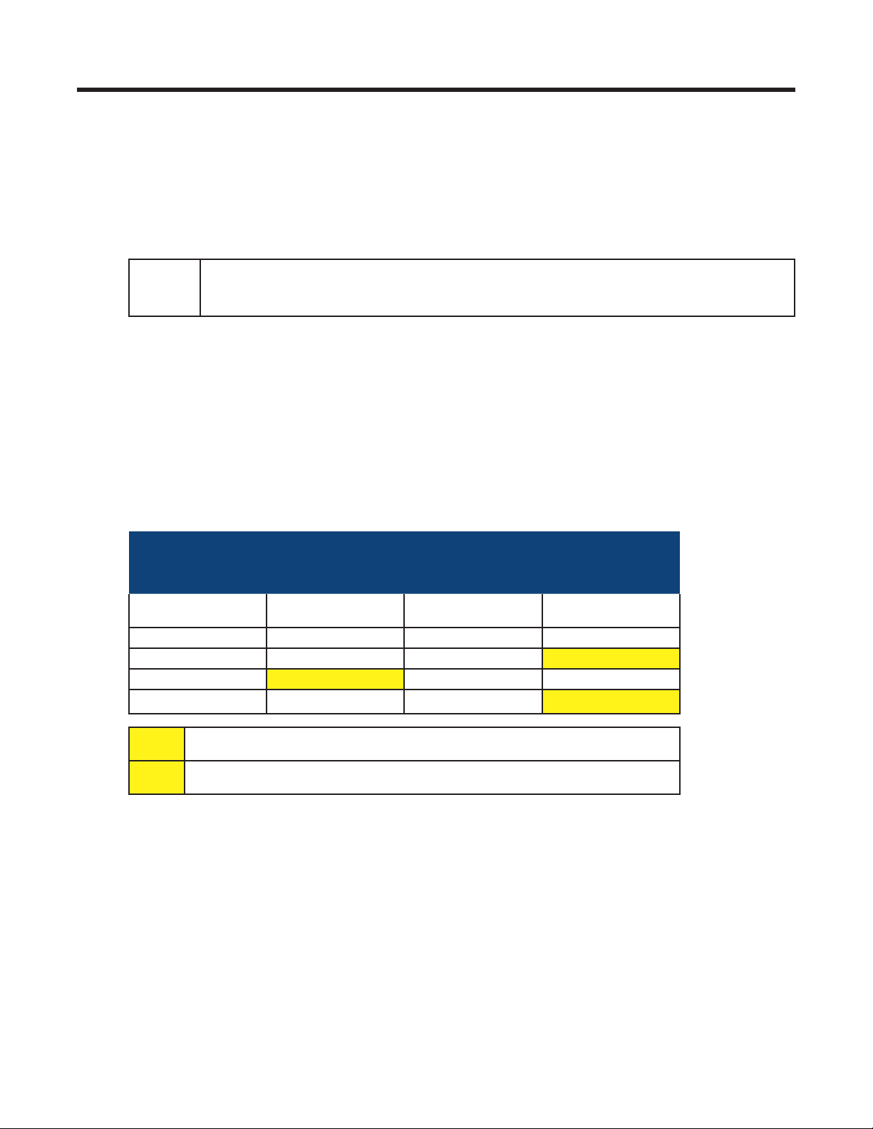
It is possible to have multiple users logged onto the controller. The following table shows the distribution
of allowed logins. (Both a User and a Supervisor are considered to have write access and only one can
be logged on at a time.)
Web Clients LCD Clients
Number of Viewers User
1-2 0 1 0
1-2 0 0 1**
1-2 1* — —
— — — 1**
or Supervisor
(Only 1 person can work with the
LCD)
Number of Viewers User
or Supervisor
* A User or Supervisor login to the web interface prevents any logins at the LCD - a
viewer currently logged on to the LCD will not be able to log back in if he logs off.
** A User or Supervisor login to the LCD prevents any logins at the web interface- a
viewer currently logged on to the web will not be able to log back in if he logs off.
2.2 Software Configuration Loading and Updates
Factory software updates and adjustments to the configuration file are possible through the Ethernet connection. The Supervisor can exclude settings and groups of settings when applying changes. A partial
configuration file can also be generated and sent to the CXC (v1.81 and above).
2.3 Customizable User Interface
The web interface can be customized to remove web browser elements that are of no interest to the user.
This menu for customizing the user interface is located in Supervisor > Customize User Interface. When
a group is unchecked, all related UI elements are removed from the browser. This includes menu items,
summary information in the View Live Status and signals and alarms.
0700015-J0 Rev B
7

2.4 Mixed Rectifier System
All controllers, except the CXCU, allow one type of Alpha Pathfinder model rectifier to work in parallel with
one type of Alpha Cordex model rectifier, for example, a PFM 48V-10kW or PFM 48V-3kW with a CXRF
48-3.6kW. Another example is a PFM 24V-3kW with a CXRF 24-3.1kW. The load share of each rectifier is
based on the percentage of the maximum output current of the rectifier; see Rectifier Report (4 . 7. 2 ).
The Pathfinder rectifiers are not shown under Upgrade Firmware as that submenu applies to Cordex
rectifiers and smart peripherals only.
2.5 Safe Voltage
The Safe Voltage is the voltage that the rectifiers default to if they lose communications with the controller.
The Supervisor can set the default system voltage (Safe Mode) that will be used if the communications to
the Cordex rectifiers fails. This feature has a time delay that varies according to the rectifier. Most rectifiers will revert to Safe Mode after five (5) minutes. The rectifier manual lists the default parameters.
Note: In general, the open circuit voltage for VRLA batteries is determined to be a point where discharge
or over charge will not occur.
2.6 Power Save
The Power Save feature enables the Supervisor to improve operational efficiency by running only the
necessary number of rectifiers. For example, when the load is significantly less than the available system
power, the controller shuts down one or more of the rectifiers so that the remaining rectifiers operate with
greater efficiency at a higher current level. A short (one-minute) time delay or hysteresis is built in to avoid
nuisance alarms and to prevent changes if the load is fluctuating.
With Power Save, rectifier usage rotates on a weekly basis to share the service time. Power Save comes
into effect when a minimum discharge or load current (~2.5% of maximum current of one rectifier) is
achieved. Battery charge current limit calculations are based on the rectifiers that are running.
The Power Save feature is suspended during Battery Test mode. See 4.12 . 4.
NOTE:
The Remote Shutdown setting must be enabled for the rectier (see Rectiers > Congure
Rectiers) to operate in Power Save.
2.7 Auto DC Priority
The inverters can be configured to automatically switch to DC Priority mode when a custom alarm is activated. The alarm could be triggered by a digital input such as a signal from an alternative energy source
– a fuel cell for example that has just switched on.
When the custom alarm activates, the CXC automatically switches the Inverters to draw from DC power
as much as possible. When the alarm is deactivated, the command is sent to return to AC Priority. (Custom alarms are configured from Alarms-> Configure Alarms.)
For more information, see section 6.4.7.
2.8 Battery Temperature Compensation
The automatic battery temperature compensation feature (Temp Comp or TC) works with Cordex series
rectifiers that support CAN bus communications and Pathfinder series rectifiers that support RS-485
remote communications. Temp Comp may be active in either the Float (4.9) or Equalize (4.10 ) mode.
Temperature inputs are available on the CXC for monitoring a lead acid battery string. Temperature sensor readings can be displayed on the GUI in either the Celsius (°C) or Fahrenheit (°F) scales.
The CXC has the flexibility to display the breakpoints in voltage and temperature. The breakpoints can be
entered as voltages or temperatures.
The detection of a thermal runaway is limited to a programmable Battery Over Temperature Alarm. The
Supervisor can select the temperature that triggers an alarm.
8
0700015-J0 Rev B

2. 8.1 Theory of Battery Temperature Compensation
The battery life expectancy and performance is directly related to the battery ambient temperature. The
optimum battery temperature during operation is 25°C (77°F). Without compensation, battery life is seriously compromised at temperatures above 25°C, while battery performance is reduced below 25°C.
Adjusting the battery’s float or equalize voltage to correspond with temperature fluctuations ensures
maximum battery performance and life expectancy. With the CXC, this can be accomplished by using
the software’s built-in automatic temperature compensation function. This function adjusts the system
voltage, ever 60 second, as the temperature changes and provides for a maximum voltage change of
0.1V over this interval.
Temp Comp occurs at standard rates commonly referred to as slope-compensation settings. For maximum performance, the battery slope compensation must be matched to the setting recommended by the
battery manufacturer. Do not confuse this with the slope regulation, which refers to the process of regulating the current among a group of parallel-operating rectifiers.
The Temp Comp feature uses programmable breakpoints, which are the points that Temp Comp ceases.
Further temperature decreases or increases do NOT increase or decrease the output voltage. This protects the connected load and battery from excessive voltages. As Temp Comp is active in either float or
equalize mode, set breakpoints with this in mind.
When temperature compensation is enabled in Equalize Mode, the CXC uses the equalize voltage setting
as the center point around which to make Temp Comp voltage adjustments.
When temperature compensation is enabled in Float Mode, the CXC uses the float voltage setting as the
center point around which to make Temp Comp voltage adjustments.
2.8.2 Operation of Battery Temperature Compensation
The CXC can accommodate up to four sensors that monitor lead acid battery temperatures. If more than
one sensor is used and the temperature readings are within 5°C (9°F) of one another, the temperature
readings are averaged. If the reading differences exceed 5°C, a thermal runaway is assumed in one
battery string and the reading changes from the average reading to the highest. If any reading suddenly
jumps outside the normal range (i.e. leads are cut or opened), that reading is discarded and the associated Temp Sensor Fail alarm is activated. The temperature reading then returns to the average for the
remaining sensors, or to the next highest reading.
Temp Comp has been programmed as a low priority item. All other commands and operations take
precedence over Temp Comp. If a command is issued during a Temp Comp cycle, the cycle will be put
on hold until the command is completed. If any operation is happening when the Temp Comp cycle occurs, the cycle is put on hold until the operation is completed. Temp Comp resumes when the command
or operation completes. The Temp Comp feature can be enabled or disabled in the CXC Batteries menu
(“6.5.1 Temperature Compensation” on page 50.
2.9 Battery Auto Equalization
Auto Equalize (Auto-EQ) is a protective feature designed to ensure optimal lead acid battery life and performance. With the CXC, auto equalize is used for two basic purposes: (1) for providing a quick battery
recharge after an AC power failure, and (2) as a long-term battery maintenance feature.
Refer to the battery manufacturer’s recommendations for equalization charging.
2. 9.1 Battery Charge Auto Equalize
Battery Charge Auto Equalize can be used after a prolonged AC power failure when the battery voltage
has decreased to a low level.
Once battery voltages have decreased below the auto equalize low voltage threshold, the CXC enters an
armed mode. When AC power returns, the system voltage begins to increase and charges the batteries.
Once the system voltage increases to the high voltage threshold, the CXC enters the equalize mode
and begins to equalize the battery charges for a period specified by the Supervisor in the AUTO-EQ
DURATION submenu. This is done to ensure the EQ duration is not effectively reduced by the time it
takes to recharge the battery to the nominal system voltage.
0700015-J0 Rev B
9

2.9.2 Periodic Auto Equalize
Periodic Auto Equalize can be used for maintaining the long-term integrity of a battery string. Over time,
individual battery cell voltages may vary greatly. To ensure that the batteries remain in optimum condition,
they should be equalize charged at regular intervals. The CXC enables the Supervisor to program the
time between automatic equalize charging of the battery string in the AUTO-EQ INTERVAL submenu.
2.9.3 Battery Current Termination (BCT) Equalize
The BCT Equalize feature provides an alternative method of ending the EQ mode early to prevent overcharging of the battery. Once enabled, it is only active when the EQ mode is caused by a Charge Auto
Equalize.
BCT EQ terminates the Charge Auto EQ when the battery current falls below the BC Threshold setting.
Upon initial activation of the EQ mode that is triggered by the Charge Auto EQ feature, the CXC waits
for one minute of system stabilization time before monitoring the battery current for BCT EQ. After one
minute, the battery current is checked about once per second to see if the current has fallen below the
BC Threshold.
When the battery current falls below the BC Threshold and remains below the threshold for three seconds, the EQ duration is replaced with the BCT duration. After this time, the system returns to FL mode.
2.10 Battery Monitor and Charge Current Control
The Battery Monitor feature enhances the CXC’s capability to provide information about the battery to
the user. Charge Current Control helps to increase battery longevity by keeping the battery current within
specified limits.
Charge current to the battery during recharge is limited to a value that is programmed by the Supervisor.
This value is derived from the battery manufacturer’s specification sheet and entered by the Supervisor.
A battery run time prediction is performed while the battery is supplying power to the load. The CXC
collects data to estimate the time it takes for the battery to be drained. If the Battery Monitor feature is
enabled and the battery is sourcing current to the load, a time estimate appears in the Mode Status
screen. A runtime estimate is also available in the Analog Signals display, which can be enabled for
display status in Signals > Configure Signals > Controller Signals.
During an AC outage or Battery Test, the data is collected to calculate a capacity prediction. A capacity
of 80% means that the battery is due to be replaced. The accuracy of this improves as the battery undergoes more discharge cycles.
2.11 Battery Test Scheduler
A battery test scheduler is built into the software. The test can be set to a frequency of a fixed number of
days apart, or set to a specific day of the month.
2.12 Low Voltage Disconnect Operation
Whenever the system parameters require that the LVD be activated, a 60-second countdown and audible
warning begins. When the countdown reaches zero, the LVD is activated. During this countdown, an icon
on the GUI can be pressed to evoke a prompt to inhibit LVD controls – activated by entering the Supervisor password. There is a 10-minute time-out for this. See also LVD Inhibit 6.8.2.
2.13 Signals Management
The Supervisor can view and edit a signal equation for a selected signal. The Supervisor can also configure custom signals; properties can be modified or disabled as required. All signals in the system can be
selected for a signal equation builder making it possible to combine logic conditions and analog values
to generate an alarm.
The Supervisor can select which Temperature Sensor to enable for the Battery Temp Sensor Signal.
There are 20 Custom Signals which the user can set by either SNMP or using the equation builder. Note
that for any particular signal, only one of these options can be selected. If the user chooses to set by
SNMP, any equation associated with that signal will no longer be evaluated. Similarly, if a signal is selected to be set by equation, SNMP “sets” made to that signal will be ignored. Because SNMP only allows
10
0700015-J0 Rev B

integer values and the CXC may require numbers accurate to two decimal places, values are multiplied
by 100 before sending over SNMP. So, for example, to set a signal to a value of “1”, the user should actually do an SNMP set with value “100”. Similarly, a signal with value “1” will be received by SNMP as “100”
and should be divided by 100 to determine the actual signal value. Note also that since signal values are
not saved over a CXC reset (but instead re-evaluated after reset), any value previously set by SNMP will
be lost during reset and the signal will go back to value “0”
2.14 Statistics and Historical Data
The CXC is capable of tracking several statistical parameters on a daily basis: analog statistics, for example, and triggered items such as battery log and event log.
Data is stored in local memory and can be accessed via a web interface (see Data Logging in Section
6.7. 3 ). The logged data is comma-delimited so it can automatically viewed in rows and columns in MS
Excel. The data is stored on a first-in-first-out basis.
2.14.1 Analog Statistics
All statistics, to a maximum of 90 records (one per day) contain a time stamp and date. Daily analog
statistics include the minimum, maximum and average of:
Load Voltage Load Current
Battery Voltage Battery Current
AC Mains Battery Temperature
Total Rectier Current Average DC Voltage
Average AC Voltage Number of Acquired Rectiers
Number of Sourcing Rectiers Ten Custom Signals
2.14. 2 Battery Log
A maximum of 40 records can be logged for battery statistics and events. The Battery Log contains the
following:
Event Type Capacity Rating
Battery Test Start Time Depth of Discharge
Discharge Duration Time Capacity
Amp Hours Delivered Recharge Duration
Amp Hours Recharge Return Peukert Number
1-5 Max. Midpoint Deviation Discharge Data1
1-5 Max. Midpoint Deviation Recharge Data2
Battery Current/Average Battery Current Battery Temperature/Average Battery Temperature
Battery Voltage/Battery Test End Voltage Open Circuit Voltage
Battery Test Result
During a battery discharge, active battery log information is displayed in a row above the Battery Log.
This information is then no longer available after the battery has finished recharging.
The Battery Log also provides support for very slow discharges. This is accomplished by saving intermediate battery log information in the event of controller power loss before battery recharge completes.
When a battery test (BT) is started remotely, the battery log shows Remote BT in the Event Type column.
0700015-J0 Rev B
11
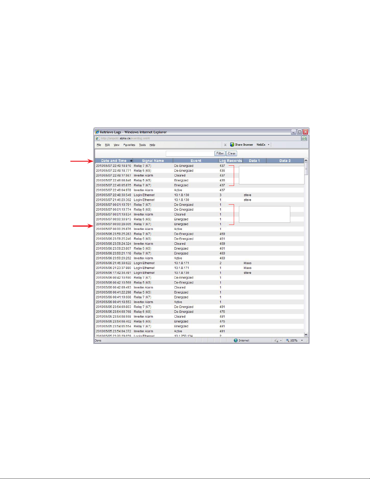
2.14.4 Event Log
The CXC can record up to 500 events. Each unique event is stamped with the date and time. Multiple
events are time stamped for the first daily occurrence and then the accumulated total is shown at the last
daily occurrence of the event. Refer to Relay 7 in the following event log.
Some of the events include the following:
• All alarm events (activation and deactivation).
• Rectifier alarm details.
• Any change of state of the digital inputs.
• Other miscellaneous events; such as, rectifiers being turned off or on due to the Power Save feature.
Once the maximum number of events have been recorded, the oldest events are erased as new events
are added.
Click on
column
heading
to sort by
column
Total number of occurrences
of Relay 7 energizing and deenergizing.
Event log
2.14.3 Data Logging
This feature of the CXC web interface allows the user to perform complex/custom configurations of the
data gathered by the Alpha controller. Various ways of setting the log frequency/limit and start/stop triggers enables greater management of the events for collection.
The data is stored in files showing the records associated with each for easy archiving and retrieval. File
Save Option enables a FIFO (first in first out) or “Stop when full” means of data collection.
Recommended size is up to seven signals and a maximum one thousand entries, as very large log files
may not be viewable. If the datalog screen comes up blank, the log is too large to be displayed.
First daily occurrence
of Relay 7 energizing
and de-energizing.
Figure 1 — Event Log
12
0700015-J0 Rev B
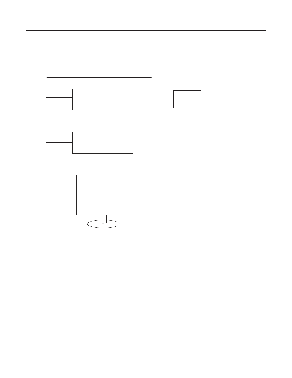
3. User Interface Options
This chapter provides an overview of the following user interfaces:
• LCD
• Web interface
A user with a Supervisor access level can make changes to parameters. A user with a User access level
can update inventory, make changes to system voltages and navigate through menus.
Win CE + Alpha browser
CXCU
CXC Controller
with expanded memory
PC running
Microsoft IE
or Firefox
Panel PC
5.7″ Color Touchscreen LCD
LCD
160x 160 pixel touch
screen liquid crystal display
0700015-J0 Rev B
13
3.1 LCD Graphical User Interface
This interface is a 160 x 160 pixel touch screen with interactive hot spots that call forth more screens. The
best tool for navigating these pages is a stylus (a small pen-shaped instrument). Make selections by tapping the stylus on the screen.
Auto-Logout Timeout
After 20 minutes of inactivity (no user input), the CXC automatically logs off the user. The CXC discards
any unsaved changes made by the user while logged in the system and returns to Normal Operation
mode. The access level is reset to the default user access and the screen continues to display live data.
Backlight Timeout
After one minute of inactivity (no user input), the CXC automatically turns off the LCD backlight.
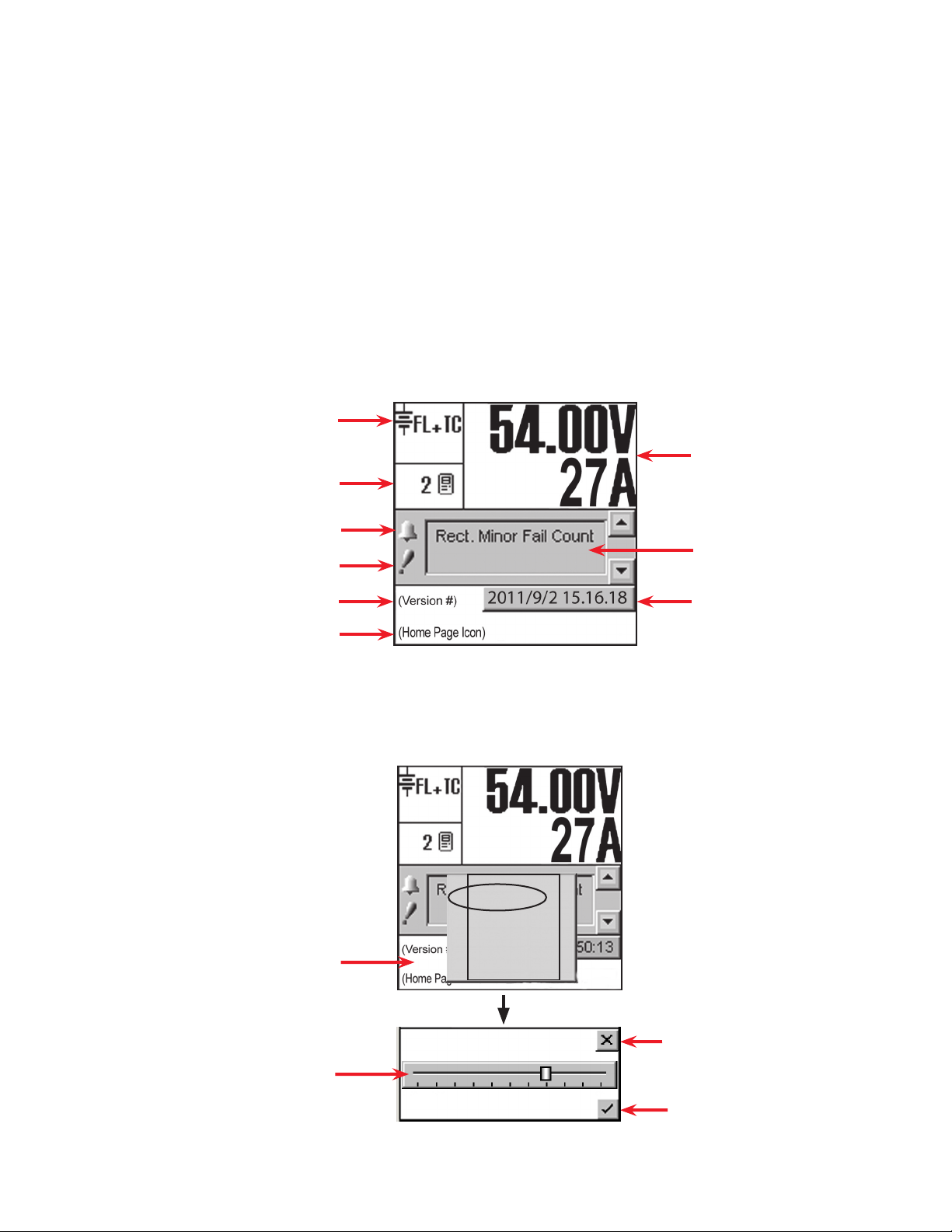
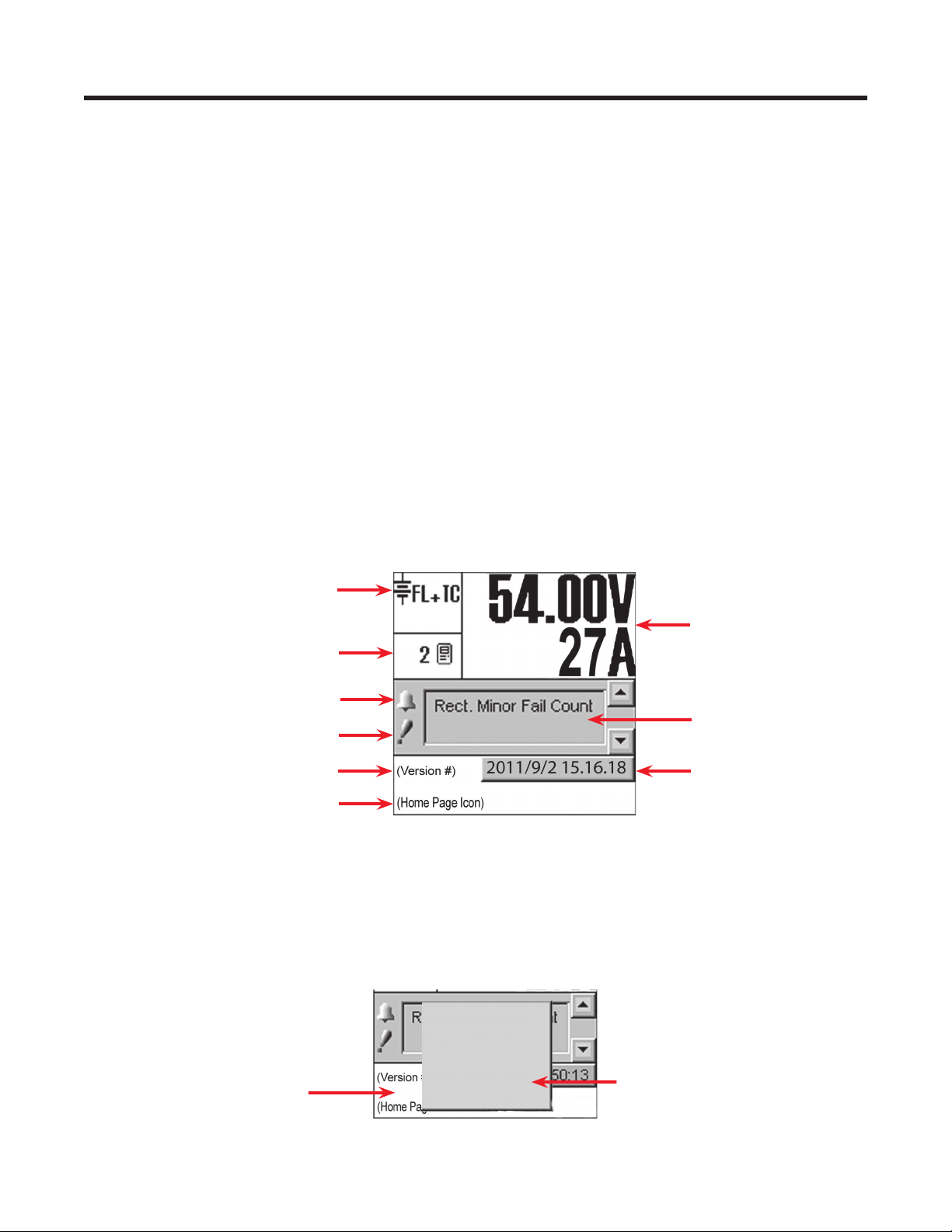
3.2 Home Screen (Default Operating Screen)
On startup the home screen shown in 2.1 appears. This GUI displays system status information and
monitors all input channels. See Chapter 4 for operating procedures with the LCD interface.
Mode Status
Rectiers Information
Converter Report can also be accessed by tapping this area
Audio Alarm enable/disable
Priority icon
Software Version
Home Page Icon, tap to login
Figure 3 — CXC default operating screen
3.3 Contrast Adjustment of the GUI
Tap the Home page icon and then tap Contrast on the pop-up window. The following figure shows the
contrast adjustment window. Use the slider on the GUI to adjust contrast as desired.
Tap the Home Page icon
Analog Signals Display
Alarm Indication
Date and Time
Login
Contrast
Reset
0: English
1: (C hinese)
2: Français
14
Discard changes and return to
previous screen
Tap slider to increase or decrease con-
trast of GUI as required
Accept changes and return to
previous screen
Figure 2 — Contrast adjustment pop-up window
0700015-J0 Rev B
3.4 Menu Navigation — LCD
Figure 7 illustrates the LCD menu structure.
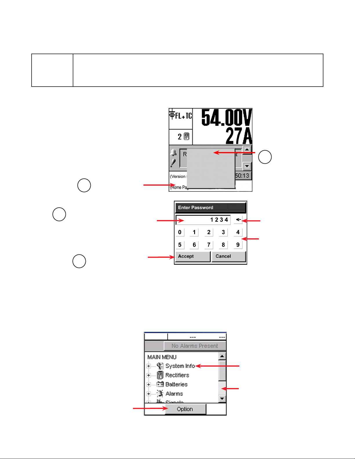
3.4 .1 Login (password entry)
NE W FEATURE
Follow steps 1 through 4 to login.
Once the password is verified, a
pop-up window provides acknowledgement; e.g., Supervisor Access
Granted.
3
The new Client Login Control feature allows up to three logins (see the feature description in
section 2.1).
If the number of logins has reached the maximum, a pop-up window appears with the warning:
Another operator is currently logged in.
Tap Home Page Icon.
1
Each character of the password entry appears
in this window for verication. Enter:
• Viewer – 0000 (read only access)
• User – 5678 (read and limited write access)
• Supervisor – 1234 (read and write access)
Login
Contrast
Reset
0: English
1: (C hinese)
2: Français
Tap to login.
2
Use the backspace key to
erase last entry as needed.
Use number keys to enter
password.
Tap to accept or cancel
4
Figure 5 — Password entry pop-up window
3.3.1 Menu Navigation Overview
The MAIN MENU screen appears on login. The folders with a plus sign can be expanded to show the
menu subcategories. See section 3.4.5 for the complete LCD menu structure and Chapter 6 for a complete description of the menu options.
Option button to logout
or save changes.
FL + TC
Figure 4 — Menu navigation screen
54.00V
250A
Tap on the folder icon or
label to expand.
Sliders and scroll bars are
used for navigation
0700015-J0 Rev B
15
3.4.2 Changing and Saving Settings
1. When changes are complete, return to the MAIN MENU navigation screen and press the OPTION
button to evoke the SAVE/LOGOUT pop-up window.
2. Select SAVE to save the new settings.
3. A pop-up window Save Complete confirms the selection (select the X icon to close the pop-up).
If no changes have been made, then saving in menu navigation results in a prompt (pop-up window):
There are no changes to save.
In each case, tapping the X button clears the pop-up from the active area and remains in menu navigation. The Supervisor retains the security access level to continue making changes and does not return to
the home page.
3.4.3 Logging Out
Tap the Option button to logout of the menu navigation screen (a pop-up window appears) and return to
the home page.
If changes have been made, another pop-up window prompts the user with Save or Discard buttons. In
either case, the active area returns to the home page and a pop-up window confirms the selection. Tapping the X button clears the pop-up from the active area.
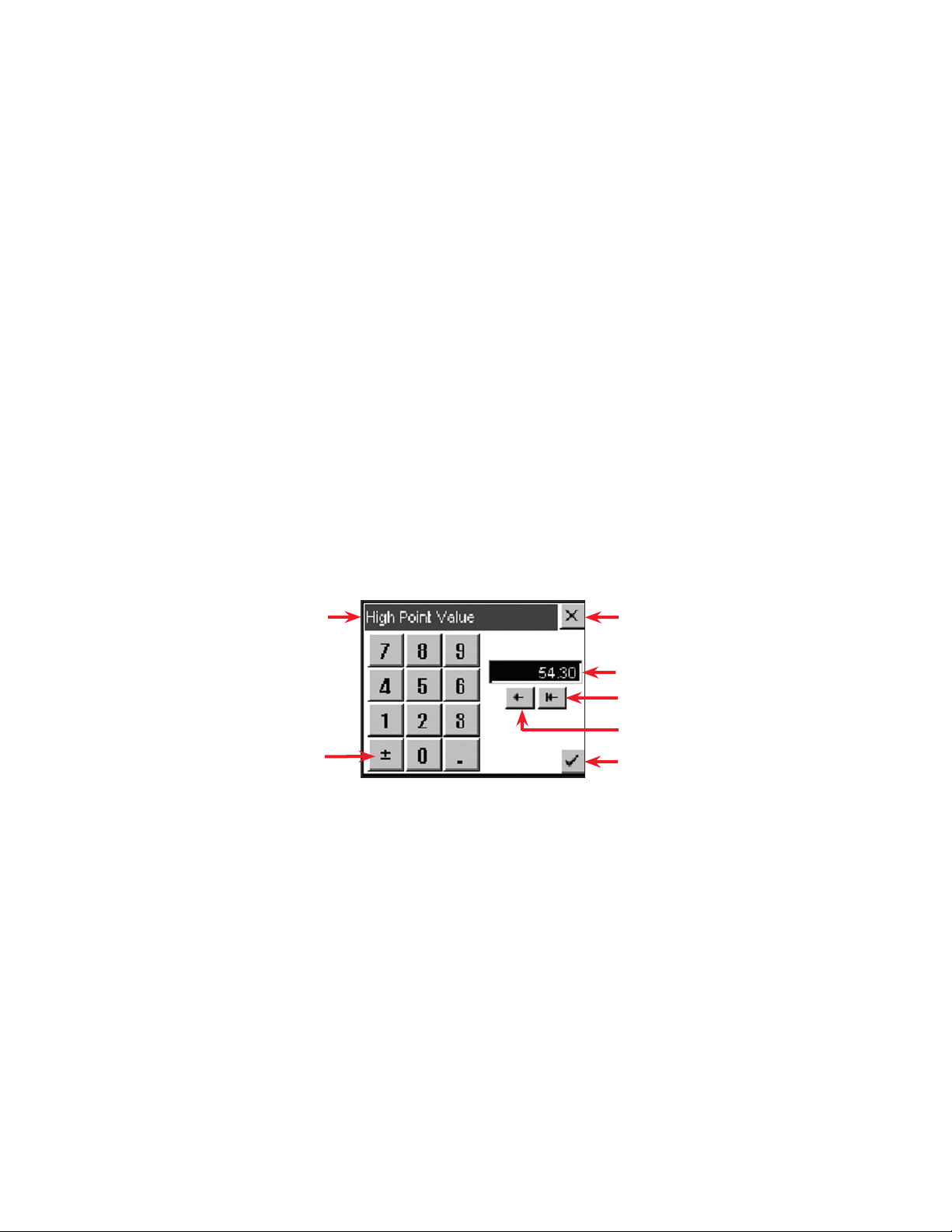
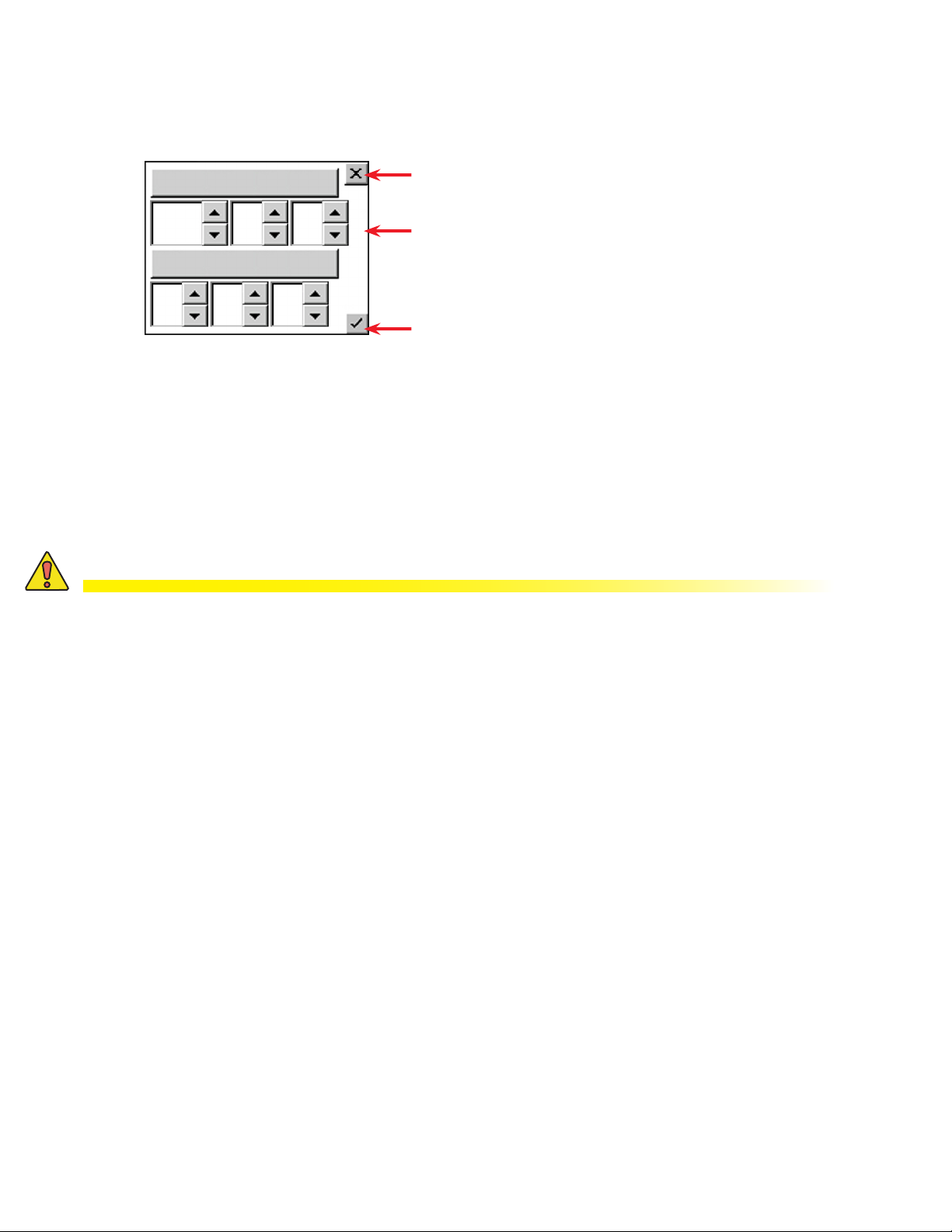
3.4.4 Virtual Numeric Keypad
Whenever a numeric field is selected, a virtual numeric keypad appears (in a pop-up window) to enable
editing of the value.
Tap the keypad to edit or enter a value. Use the virtual function buttons described below to navigate,
cancel or accept.
Name of value being edited
Toggle from positive to negative
3.4.5 LCD Menu Structure
Figure 7 shows the menu structure for all categories except the Inverter category which is listed below:
• AC Input Groups
• DC Input Groups
• AC Output Groups
• Auto DC Priority
Cancel entry and close window
Initial value of the eld
Clear entire eld
Clear one number at a time
Accept entry and close window
Figure 6 — Virtual numeric keypad pop-up window
16
0700015-J0 Rev B
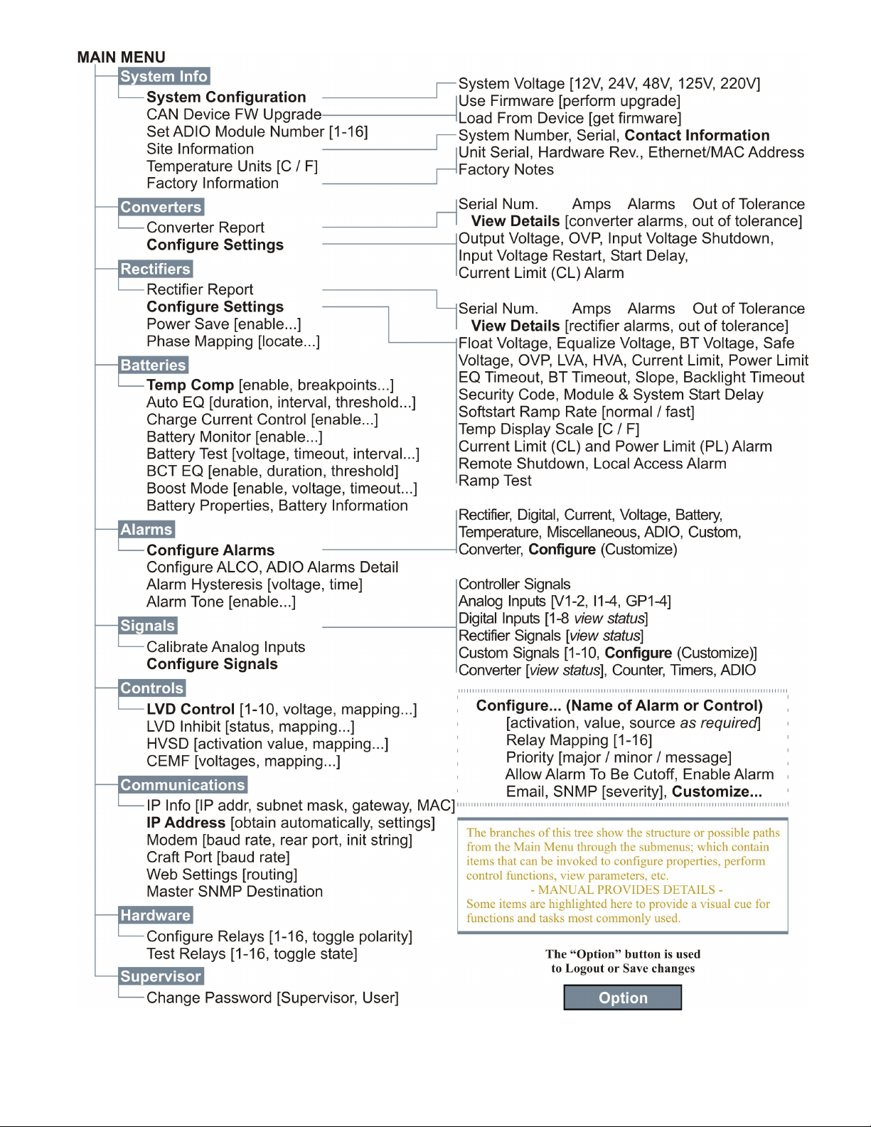
Figure 7 — LCD Menu structure
0700015-J0 Rev B
17

3.4.6 LCD Touch Screen Calibration
Perform the following steps to calibrate the touch screen from the home screen: Complete each step
within 20 sec or the calibration is ignored.
Both the targets must be tapped correctly for the calibration to take effect to prevent the calibration from
changing dramatically from the default.
1. Perform a diagonal action or «swipe»
from the top right area of the LCD to
the bottom left area:
2. Tap on the center of the first target
within 20 seconds to complete this
step.
Count down
timer
3. Tap on the center of the second target
within 20 seconds to complete the
calibration:
Count down
timer
18
0700015-J0 Rev B
4. Operation using the LCD GUI
This chapter briefly describes operation with an LCD interface. The following steps are a summary of
operating procedures on start up. The sections that follow expand on each of the steps
1. Initiate the startup routine by applying power to the CXC. (Close the battery breaker or close the
converter and rectifier input and output breakers.)
2. The CXC performs a short self-test as it boots up. The scrolling pattern of the LEDs indicates activity.
Alarm alerts are normal. Wait for the self-test to finish.
3. Check and adjust the alarms and control levels in the CXC submenus.
4. Check and adjust the group settings in the CONVERTERS and RECTIFIERS submenus. Parameters
to be adjusted include float, equalize voltage, etc.
5. Verify the relevant COMMUNICATIONS settings.
6. Program the CXC relevant TEMP COMP and AUTO EQUALIZE settings.
7. Test the relevant relay OUTPUT ALARM\CONTROLS such as Major Alarm, CEMF, etc.
4.1 Start-up
When the CXC is powered-up or reset, it performs a 15 second self-test before displaying the Cordex
logo and identification messages. The three front-panel LEDs illuminate temporarily, and then extinguish.
The Graphical User Interface (GUI) then displays system status information. Tap the active areas shown
in the following screenshot of the home page. Use a stylus pen to activate navigate through the touch
sensitive screens.
Mode Status
Rectiers Information
Converter Report can also be accessed via this active area
Alarm condition icon
Priority icon
Software Version (reporting)
Home Page Icon, tap to login
4.2 Language Selection
The user can select English, or Chinese characters for the display of text labels and messages. Language files can be uploaded via web interface. The CXC can be set up for a maximum of three language
files (two default plus one other) at one time pending availability.
Tap the Home page icon at the lower left of the home page and select language from the pop-up window
shown in the following figure:
Tap Home page Icon
Figure 8 — CXC home page
Login
Contrast
Reset
0: English
1: (C hinese)
2: Français
Analog Signals Display
Current Alarms
Date and Time
Make language selection
0700015-J0 Rev B
Figure 9 — Language selection on home page
19
4.3 Date and Time
To change the date and/or time, tap the area where the date and time are displayed on the home page
(below the Alarm Indication). Tap the up/down arrows to change the date (year, month, day) and time
(hour, minute, second) settings. tap this area of the screen to enter a new window of operation.
Discard changes and return to the
previous screen
2010 10
09
All CXC models (except CXCi and CSCM1) provide battery backup of time and date.
With the web interface, SNTP (Simple Network Time Protocol)can be used to synchronize the CXC device time with an external source; i.e., the user’s network.
30 00
Figure 10 — Setting the Date and Time
10
Tap arrows to decrease or increase
values.
Accept changes and return to the
previous screen.
4.4 Resetting and Powering Down
4.4.1 Reset
CAUTION!
During reset, the Controller may need to run a defragmentation cycle. Cycling of the LEDs on
the controller front panel indicate that defragmentation is in progress. A full defragmentation
can take up to 20 minutes to perform. DO NOT POWER DOWN the CXC during this time.
A reset enables the CXC to finish saving files to flash memory before a power down or restart.
1. Tap the Home page icon and then tap Reset on the pop-up window (see Figure 9. A new pop-up
window alerts the user “You are about to perform a system reset.”
2. To abort the operation, tap Cancel or the X button to clear the pop-up from the active area.
3. To proceed, tap Accept and a pop-up window notifies the user “Performing Reset, please wait…”
This window is then replaced with a window showing a timer counting down from 60 seconds and a
Reset Now button. A message will appear in this window to notify the user “It is now safe to reset the
system”.
4. Either tap the button or wait for the timer to count down and the operation proceeds automatically to
completion.
The screen goes blank and the LEDs flash as the CXC performs a short self-test before returning to Normal operating mode.
4.4.2 Powering Down
To power down the system, complete steps 1 through 3 under Reset.
It is safe to power down when the message appears “It is now safe to reset the system.”
20
0700015-J0 Rev B
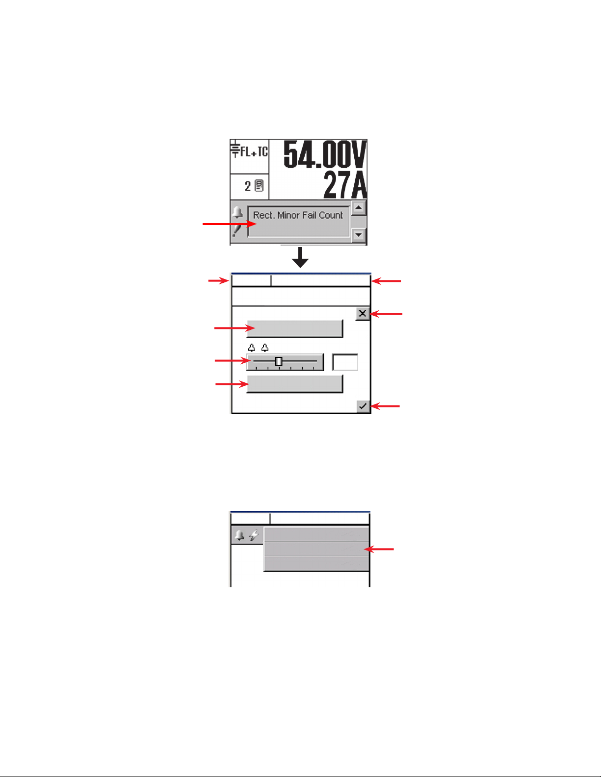
4.5 Alarm Display and Configuration
If the Alarm Indication window in the home screen indicates an alert (such as an active alarm and the
priority of the condition) tap the display area to enter a window of operation for alarm display and configuration.
Tap the Alarm Indication display
Mode (+Temp Comp) display
Tap to silence active alarms
Use slider to change alarm scroll rate
Tap to view alarm histor y
4.5.1 Silence All Alarms
Tap Cutoff All Alarms button to silence active alarms. In addition, on any screen where the alarm indication is shown, tapping the alarm indication button displays a pull-down menu (F igure 11) for alarm cutoff
(also known as ALCO, see 6.6.9):
FL + TC
54.00V
250A
Alarm scrolls here…
Cutoff All Alarms
Scroll Rate
1 s
Show Alarm History
Figure 12 — Alarm indication display screen
FL + TC
54.00V
250A
Alarms Display Here
Cutoff All Alarms
Cancel
Battery Volts and Load
Current display
Discard changes and return to
previous screen
Accept changes and return to
previous screen
Use pull- down menu to
cutoff all alarms
0700015-J0 Rev B
Figure 11 — Alarm cutoff pull-down menu
21
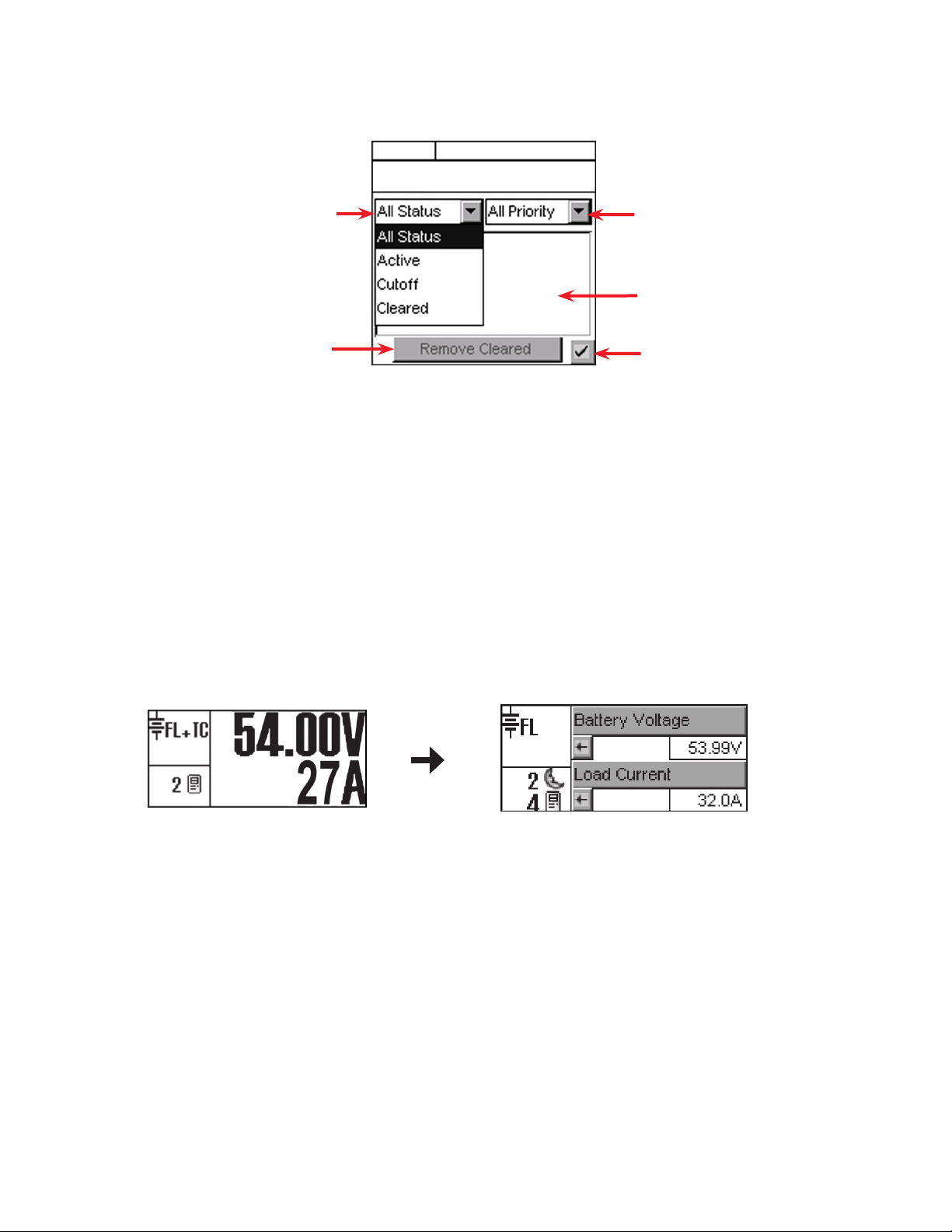
4.5.2 Alarm History
Tap Show Alarm History to link to another screen that lists past alarms. Two pull-down menus enable the
user to select which alarms to display according to status and priority:
Use pull- down menu to select
status as shown
Tap to Remove Cleared
alarms from display
4.5.3 Alarm Configuration
Login to the controller and select Alarms from the main menu (see section 3.4 for menu navigation). Examples of alarm settings are power system high/low voltage alarms, AC Mains high/low voltage alarms,
supervisor programmable alarms and alarm tone enable (audible alarm buzzer). For details, see section
6.6.
4.6 Signals Display
The Analog Signals display area on the home page shows two lines of text for system voltage and current
by default. Tap this active area to decrease the font size and display four lines of text showing the system
values and the corresponding labels. Tap the arrows beside the system values to return to the larger font
of the normal (default) home page.
The large font reappears after 20 minutes of inactivity (no user input).
FL + TC
54.00V
250A
Alarm will scroll here…
Figure 13 — Alarm History screen
Use pull- down menu to select
priority, either major, minor,
message, or all
Alarms display here in a list
Verify action and return to
previous screen
22
Figure 14 — Signal display area of the home screen
0700015-J0 Rev B
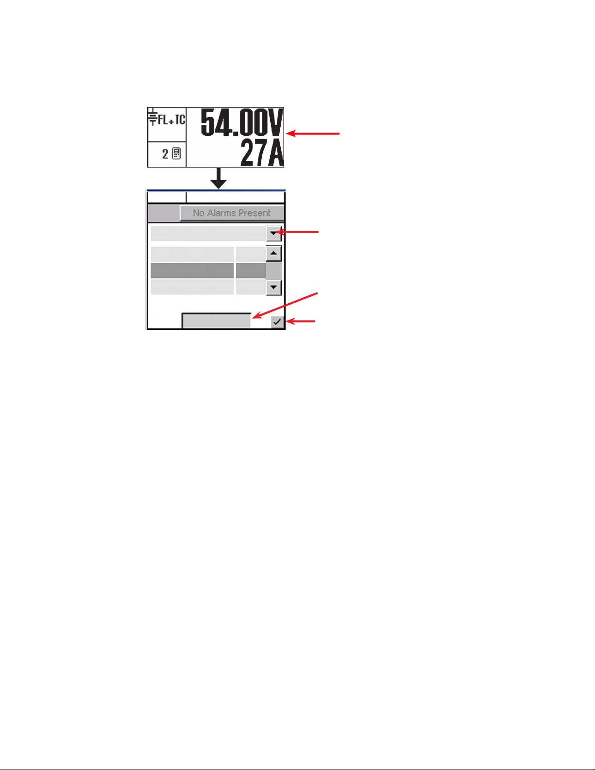
Tap the Analog Signals display on the home screen to enter an operation window for signals configuration. Or login to the controller and select Signals from the main menu (see section 3.4 for menu navigation). Section 6.7 has detailed instructions for reviewing and configuring signals.
Tap the Analog Signals display on the
home screen
FL + TC
54.00V
250A
Controller Signals
Load Current
Battery Voltage
Battery Current
250
54.00
5.4
Congure
Figure 15 — Signals display screen
Use the pull-down menu to select one of the following signals:
Controller Signals
Tap the Configure button to produce another window with a list of items to navigate, see
Section6 . 7.2 .1
Analog Inputs
Tap the Calibrate button to produce another window and list of items to navigate, see
Section 6.7.2.2.
Digital Inputs
Provides a list of digital inputs, see “Table D — Digital input channel assignments” on page
61.
Rectifier Signals
Custom Signals
Converter Signals
Counter
Timers
ADIO Signals
Provides a list of rectifier signals, see Table G on page 120.
Tap the Configure button to produce another window and list of items to navigate.
Provides a list of converter signals, see Table H on page 120.
Tap the Configure button to produce another window and list of items to navigate.
Tap the Configure button to produce another window and list of items to navigate.
Used to view live data from an ADIO device (i.e., Cordex Smart Peripherals) connected to
the CXC. Refer to Section 6.7.2.6 on page 74, Example 4.
Use drop-down menu to select
from signals list.
Tap Congure to edit the selected
menu item. Enter password when
prompted.
Accept changes and return to
previous screen
0700015-J0 Rev B
23
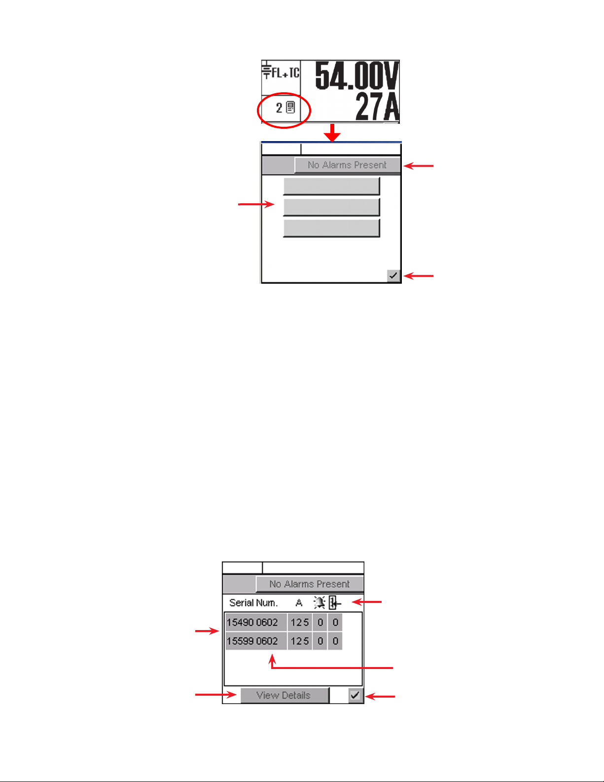
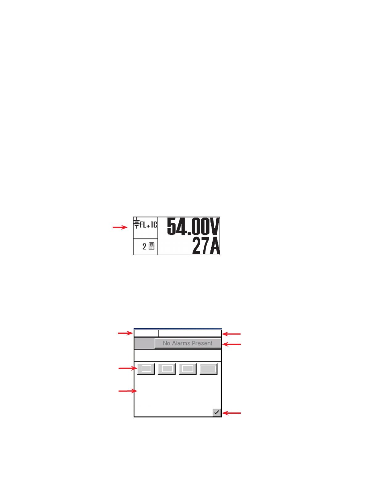
4.7 Rectifiers (and Converters) Information
Tap the rectifier display area to
enter an operation window for
converter/rectifier updates and
reports.
Select operation here
4.7.1 Inventory Update
This button enables the user to re-acquire all the attached modules to the CXC and verify the existence of
all connected modules.
Tapping this button updates the inventory and returns the user to the home page. A pop-up window appears over the home page to show a progress bar of the number of modules acquired during the update.
Tapping the X button clears the pop-up from the active area.
Inventory update must be done whenever a module is removed from the system. The system is polled
with respect to the following scenarios:
• Module has failed and is no longer able to communicate, or
• User has removed a module from the system.
FL + TC
54.00V
250A
Alarm Indication
Inventory Update
Rectier Report
Converter Report
Return to previous screen
Figure 16 — Update (inventory) and report selection screen
4.7. 2 Rectifier Report (Converter Report similar)
Tap the Rectifier Report button to generate a report of all acquired modules in the system.
A new operations window appears with a list of the rectifiers in the system. The first column lists the serial
numbers of the modules. The report then displays the current output (A) of each module (or toggle for %
of maximum output) and the number of active alarms. The right most column displays the number of settings out of tolerance (OOT per web interface).
FL + TC
Rectier (or Converter) Locate Feature
Once a module is selected, the (module)
LEDs ash briey.
Select a module and then tap View
Details to produce a new window
with pull-down menus showing all of
the alarms and settings that are out of
tolerance
Figure 17 — Rectifier (or Converter) report screen
54.00V
24
250A
Report headings for serial number, current
display (% or A), number of alarms and settings out of tolerance (OOT)
A value of ‘—‘ indicates Comms Lost
Return to previous screen
0700015-J0 Rev B
4.7. 3 Basic Programming Example
For details of the settings in the RECTIFIERS\ CONFIGURE SETTINGS menu, see 6.3.2:
1. Use the navigation arrows to scroll to the item that is to be changed; e.g. FLOAT VOLTAGE.
2. Enter a new value using the CXC virtual numeric keypad, e.g., 54.00.
Download new settings to all connected rectifiers:
3. Click the check mark in the lower right hand corner to return to MAIN MENU navigation screen.
4. Press the OPTION button to evoke the SAVE/LOGOUT pop-up window.
5. Select SAVE to save the new settings or select LOGOUT to clear. A pop-up window appears to
confirm the selection.
4.8 Voltage Mode Status and Temp Comp Settings
The Mode Status displays the current mode of operation:
• Float (FL)
• Equalize (EQ)
• Boost (BST)
• Battery test (BT)
The mode and temperature compensation (TC) appear in the upper left corner. The time duration, until
the mode changes, may also appears in that active area.
Refer to sections 4.9 to 4 .12 for a description of the voltage modes.
Mode Status
To change modes:
1. Tap the Mode Status active area to enter the mode selection screen.
2. In the screen that appears, tap the required mode button.
3. Tap the check mark button in the lower right corner to verify the selection and return to the previous
screen.
The icon for the new mode now displays in the upper left corner of the GUI.
Mode (+Temp Comp) display
Mode Selection buttons
Additional functions display
here; such as, countdowns and
status of battery runtime
FL + TC
54.00V
Battery Voltage Mode
FL
Periodic Auto-EQ Disabled
Auto BT Disabled
EQ BT
250A
BST
Battery Voltage and Load Current display
Alarm Indication
0700015-J0 Rev B
Verify action and return
to previous screen
Figure 18 — Mode selection screen
25

4.9 Float (FL) Mode
FL is the CXC default mode at start up and during normal system operation. In this mode, the rectifier’s
charge (or output) voltage is driven by the float voltage setting found in the CXC Rectifiers menu, see
6.3.2. Do not adjust the float voltage of the rectifiers when they are in Current Limit.
4.10 Equalize (EQ) Mode
Use the equalize mode to equalize charge a battery string. In this mode, the rectifier’s charge (or output)
voltage is driven by the equalize voltage setting found in the CXC Rectifiers menu, see 6.3.2
A maximum time limit for equalize charging can be programmed to prevent accidental over-charge of a
battery string. This limit is determined by the setting found in the EQ Timeout menu, see 6. 3. 2.1 0 . Do not
adjust the equalize level of the rectifiers while they are in Current Limit.
When operating in EQ mode, the text below the Mode Selection buttons (Figure 18) displays the time
until FL mode in hours.
4.11 Boost (BST) Mode
This feature provides the supervisor with the means to equalize charge the battery at a higher voltage
relative to the connected load. Activation is manual and certain conditions must be met to prevent damage to the load. A custom alarm must be created to include all the desired factors that must be taken into
account before activating BST mode. This mode will then only be permitted if the alarm is false.
Once activated, BST mode concludes with a timeout or whenever the status of the custom alarm is true
and reverts to FL mode. BST mode can also be cancelled if the conditions required to activate BST mode
have changed.
4.12 Battery Discharge Test or Battery Test (BT) Mode
The battery discharge test is used to update the status of the lead acid battery capacity.
Manual Activation Manually initiated (tap Mode Selection area and then
BT button) (Figure 18)
Auto-BT Feature BT can be set to run automatically on a periodic basis.
4.12 .1 Definitions
• End/Terminal Voltage — The voltage at which the test ends.
• Timeout — The maximum time the test can run before it is aborted.
• Period in Days — The time between each Auto-BT.
• Battery On Discharge (BOD) Alarm — indicates the battery is discharging.
4.12 . 2 Tips on Using the BT Mode
Use Charge Current Control (6.5.2) to limit the battery recharge current to the battery manufacturer’s
specified maximum value.
The resultant battery capacity estimate will be more accurate if the test is started when the battery is fully
charged. If a discharge has occurred within the last 96 hours, when a mode change to BT is selected, a
dialog box will prompt the user to confirm the mode change.
During a test, the runtime hours are accessible through the Analog Signals display or Mode Status
screen. The runtime hours reflect the time remaining in the test.
The runtime is displayed after the start of an outage and when a BOD condition is detected; i.e., battery
is sourcing current and voltage is below open circuit.
When a test is started by the remote BT feature, the battery log will show “Remote BT” in the Event Type
column.
The Supervisor can enable or disable the feature in
(BATTERIES) BATTERY TEST\AUTO-BT menu. See
section 6.5.4.
26
0700015-J0 Rev B

The BT depth of discharge (DOD) can be accessed via the Analog Signals Display; provides an additional indication of test progress.
BT information is available via the CXC battery log web page when a test is in progress. In addition, the
new battery capacity estimate can be accessed via the Analog Signals display at any time before, during
or after the test.
4.12 . 3 BT Initiation
When the test begins, an entry is made in the event log. If enabled, an alarm provides a warning to indicate that a Battery Test is in progress.
The test will continue, depending on the type of rectifier in use, in accordance with the following algorithms (as applied to lead acid batteries):
Algorithm 1 — For rectifiers that support Battery Test (BT) mode:
1. A command is sent to put the rectifiers into BT mode.
2. BT mode runs for the period set as Timeout or until BT End Voltage is reached.
Algorithm 2 — For (Pathfinder) rectifiers that do not support BT mode:
1. Rectifiers are commanded to go to nominal voltage.
2. The rectifiers are periodically scanned to be sure that they do not begin sourcing current. When 3%
DOD is reached and the rectifiers are still not sourcing current, the rectifiers are turned off.
3. The rectifier float setting is reset to the setting stored in the system controller.
4. When the system voltage reaches the end (termination) voltage or a timeout occurs, the system
controller will command the rectifiers to turn ON and enter FL mode.
4.12 .4 Activity During BT Mode
Temp Comp and Power Save features are suspended during a battery test.
When the battery is discharging, a BOD alarm is active.
During a test, the mode symbol in the upper left corner of the GUI updates to “BT.”
Runtime estimate begins at 3% DOD.
Capacity estimate also begins at 3% DOD, but is not stored unless DOD > 20%; the point at which reasonable accuracy can be assured.
4.12 . 5 AC Failure During BT Mode
If the AC fails during a battery test, the test will be aborted. This will place the rectifiers into a state that
will enable them to resume providing power to the load when AC returns. If the Runtime is being displayed, it will continue to update.
4.12 .6 Addition of Rectifiers During BT Mode
If rectifiers are added to the system when a battery test is active, they will be placed into the same state
as the other rectifiers. They are:
• Placed into BT mode (for rectifiers that support BT mode), or
• Placed into remote shutdown, or
• Set to the same voltage as the other rectifiers.
0700015-J0 Rev B
27

4.12 .7 Conditions to Watch for During BT Mode
If the voltage drops below 47 V before or when 3% DOD is reached, the test is aborted and the battery
capacity is set to 0% (resulting in a Battery Capacity Low alarm). This provides an indication that the battery is very weak . The battery capacity must be manually reset to 100%, or to the percentage of expected battery capacity before the next battery test is started, in order for the battery monitor to again attempt
to compute the battery capacity.
If rectifiers are seen to be sourcing current during the test and the battery ceases to be discharging, the
test is aborted.
4.12 . 8 Cancelling BT Mode
BT mode can be cancelled by changing mode to FL or EQ (see section 4.8).
4.12 .9 Battery Discharge Test Completion
The test is considered complete once the battery begins to charge. This could be due to the test ending
from timeout, the system reaching the end (termination) voltage or an abort condition.
Once the battery begins to charge, the recharge cycle begins. Live battery recharge information is available from the battery log web page.
4.12 .10 Remote BT Mode
This feature will force a transition to BT mode when a user-defined condition (custom alarm) is true.
When this condition is true, BT mode is entered regardless of the regular safety checks that are performed during manual or automatic changes to BT mode. BT mode stays active as long as the condition
remains true.
A check box is used to enable/disable this feature. The default is disabled. If the condition is true and the
check box is disabled, then the system will be put into FL mode.
If the condition becomes false, disabled, invalid, or the (assigned custom alarm) equation is empty, the
system will be put into FL mode.
This feature is exclusive for the Cordex series of rectifiers. If Remote BT is active and a rectifier other than
the Cordex series is added to the system then Remote BT will be aborted.
4.13 Communications
For the web interface, refer to Section 9.1 to set up network connections.
28
0700015-J0 Rev B

5. Operating with the Web and Panel PC Interface
5.1 Communication Settings
The web interface and panel PC are alike except for the communication settings to connect to the CXCU:
5.1.1 Web Interface
Refer to Section 9.1 to set up network connections between a remote PC and the CXC.
5.1. 2 Panel PC
Direct Connection
For a direct connection to the CXCU, verify that you are using a cross over cable. Configure your local
area network connection as follows:
1. Power up the panel PC.
2. Tap the Configuration (wrench) icon.
3. On the IP Protocol Settings tab, verify the following settings:
a. IP address is 10.10.10.202
b. Subnet Mask is 255.255.255.0
4. Make changes if necessary and click Apply.
NOTE: Changing the IP address of the Panel PC requires a restart of the Panel PC. A warning message
appears below the screen.
http://10.10.10.201/
Obtain an IP Address Using DHCP
Use the following IP Address
IP Address:
Subnet Mask:
Default Gateway:
Figure 19 — Panel PC IP settings
10. 10. 10. 202
255. 255. 255. 0
Application SettingsCXC Connection SettingsIP Protocol SettingsConnection Status
Cancel Apply
0700015-J0 Rev B
29

5. In the CXC Connection Settings tab, verify the IP Address of the CXCU is 10.10.10.201.
6. Tap Navigate To. The Home screen (Figure 21) appears.
http://10.10.10.201/
Application SettingsCXC Connection SettingsIP Protocol SettingsConnection Status
5.2 Getting Started
The following diagram shows navigation options available from the home page.
Alarm Cutoff
(ALCO)
Search
Select>>
Cordex Controller IP AddressSearch For Connected Controller:
10. 10. 10. 201
Cancel Apply
Figure 20 — Cordex Controller IP address
Scroll displayed
Active
Alarms
alarms
Navigate to
Alarms > View
Live Status
Alarm
Severit y
System>
Select Voltage
Mode
Number of Acquired
Rectiers
Inverters >
View Live
Rectiers >
View Live
Status
Inverter Mode = DC
to AC conversion
Line Mode = AC to
AC conversion
Number of
Acquired
Inverters
Figure 21 — Home Screen (Web Interface)
Signals > View
Live Status
Systems > View
Live Status
Status
30
0700015-J0 Rev B

5.3 Login
CAUTION: Basic authentication is cached in Firefox and the Panel PC. You must close the browser
window to clear password information and prevent unauthorized access.
Clicking any of the Home Screen icons, shown in 2.1, results in a login screen.
Login with your own name.
Anyone denied access will
know you’re logged on and the
time you spent logged in will
show up in the events log.
A Supervisor can both navigate through the menus and change values.
A User can navigate and change voltage modes (Main Menu > System > Select Voltage Mode).
A Viewer can navigate through the menus but can’t make any changes.
Default Passwords:
Viewer 0000
User 5678
Supervisor 1234
Figure 22 — Login Screen - Web Interface
5.4 Language Selection
Click the Language icon on the home page (2.1) and select a language from the list.
The CXC can be set up for a maximum of three languages (two defaults plus one other). Language files
can be uploaded from www.alpha.ca (pending availability).
5.5 Saving Changes
The following two screens show the two steps required to save a change. (This example shows a change
to the user interface.)
1
Click the Save icon.
2
Click Accept.
0700015-J0 Rev B
Figure 23 — Saving Changes — Web Interface
31

5.6 Date & Time
1. Select Controller > Date and Time from the main menu:
2. Fill in the date and time.Click the Save icon.
Figure 24 — Date & Time — Web Interface
5.6 .1 Configuring SNTP (Simple Network Time Protocol) Service
1. On a laptop or PC, view Date and Time in the Control Panel. Use the pull-down menu to select the
correct time zone. The Pacific time zone, for example, requires a time zone adjustment in the CXC of
–8:00.
2. In the CXC GUI, select Main Menu > Controller > Date and Time. Click the Enable SNTP Service
checkbox.
3. Enter the target IP Address for the SNTP source.
4. In the Time Zone Adjustment field, use the + or — button in addition to the pull-down menu to enter
the time zone adjustment.
5. Click the Save icon and Accept the changes.
6. Click Get Time Now to synchronize.
5.7 Alarm Display and Configuration
5.7.1 View Alarms
Major alarms are visible on the home screen. Use the up/ down arrows to scroll through the active
alarms.
Figure 25 — Alarms — Home page
Click the right most arrow on the home screen to display all alarms. Alternatively select Alarms > View
Live Status from the main menu.
5.7. 2 Alarm History
Select Alarms > View Live Status from the main menu. Then click Cleared Alarm History.
32
Figure 26 — Alarms history
0700015-J0 Rev B

5.7. 3 Silence all Alarms
Click the speaker icon to acknowledge active alarms. This may silence the buzzer and revert the alarm
relay to normal state depending on the global alarm configuration.
To configure global alarm parameters, select Alarms > Global Alarm Configuration from the main menu.
5.7. 4 Configure Alarms
Select Alarms > Configure Alarms from the main menu. See section 6.6 for a description of the alarm
parameters.
Ensure that the operating levels (e.g., input/output voltage, converter voltage, etc.) are within the operating parameters of the alarm and control thresholds.
Figure 27 — Configure Alarms – Web Interface
5.8 Converters
Select Converters > View Live Status for status report and alarms.
Select Converters > Configure Converters to set the rectifier parameters. Refer to section 6.2for a description of the parameters.
5.9 Rectifiers
Select Rectifiers > View Live Status for status report and alarms.
Select Rectifiers > Configure Rectifiers to set the rectifier parameters. Refer to section 6.3 for a description of the parameters.
Other menu options are Inventory Update, Power Save and Rectifier Phase Mapping—all of which are
described in section 6.3.
5.10 Inverters
Select Inverters > View Live Status for status report and alarms. Refer to Table A for menu options and
section 6.4 for a description of the parameters.
5.11 Battery Mode and Temp Comp Settings
Select System> Select Voltage Mode to change voltage mode. Refer to section Figure 3 for a description
of all battery parameters.
0700015-J0 Rev B
Figure 28 — Select Voltage Mode – Web Interface
33

5.12 Resetting the CXCU Controller
5.12 .1 Soft Reset or Power Down
A soft reset enables the CXC to finish saving files to flash
memory before a power down or restart.
From the main menu
To reset or power down the controller, select Controller >
Reset from the main menu and wait for the Reset Now pop-up
to appear.
CAUTION!
During reset, the Controller may need to run a defragmentation cycle. Cycling of the LEDs on
the controller front panel indicate that defragmentation is in progress. A full defragmentation
can take up to 20 minutes to perform. DO NOT POWER DOWN the CXC during this time.
From the controller front panel
The controller front panel has two reset buttons – both are recessed and require a stylus or pen to initiate the reset.
The upper reset button has two modes of operation. When
pressed momentarily, the unit beeps twice and then the microprocessor resets. The LEDs flash as the CXC performs a selftest
before returning to normal operating mode.
To reset the IP address, press and hold the front panel reset button for three seconds. The unit will beep three times, reset the IP
address to 10.10.10.201 and disable DHCP. The settings are saved
and the unit resets.
Soft reset
button
Hard reset
button
5.12 . 2 Hard Reset
If the controller is hung up, a hard reset can be initiated by pressing the lower reset button. No files are
saved to flash memory.
5.13 Saving Configuration Files
When all changes are made, select Main Menu > Logs and Files > Manage Configuration File to save the
configuration file:
Figure 29 — Manage Configuration File – Web Interface
Figure 30 — CXCU controller
34
0700015-J0 Rev B

5.14 Summary of Menu Navigation
Table A — Web Interface Menu Structure
Menu Sub-Menu Menu Sub-Menu
System
x View Live Status
x Configure System
x Select Voltage Mode
x Upgrade Firmware
x User Inventory
x System Inventory
x Inventory Update
Controller
x View Live Status
x Factory Information
x Date and Time
x Temperature Units
x Upgrade Software
x Upgrade Bootloader
x Reset
Converters
Rectifiers
Alarms
x View Live Status
x Configure Converters
x View Live Status
x Configure Rectifiers
x Inventory Update
x Power Save
x Rectifier Phase Mapping
x View Live Status
x Configure Alarms
x Global Alarm Configuration
Inverters
Batteries
Signals
x View Live Status
x View Group Status
x Group Mapping
x Set Inputs
x Set Output
x General Settings
x Manage Config File
x Auto DC Priority
x View Live Status
x Configure Batteries
x Battery Information
x View Live Status
x Configure Signals
x Configure Data Logging
Controls
Hardware
Supervisor
0700015-J0 Rev B
x View Live Status
x Configure Controls
x Configure Relays
x Test Relay
x Test Modem
x Change Password
x Customize User Interface
Communications
Logs and Files
x View Live Status
x Configure Communication Pa-
rameters
x Event Notification Destination
x SNMP Configuration
x Retrieve Logs
x Manage Editable Text Files
x Manage Configuration File
x Manage Language Files
35

6. System Configuration: Programming and Adjustments
The CXC menu structure (Figure 7) consists of two basic components: Menu Categories and Sub-Menu
Items. This chapter describes each of the CXC menu items, including alarms, controls and configuration
items. They are arranged, as they appear in the touch screen menus subject to product enhancements.
Items specific to the CXC web interface are indicated separately.
6.1 System Info
This menu category consists of factory, site and system data. Information pertaining to the CXC, the
related site and system can be accessed here. The Supervisor can set parameters; such as, system
number (Figure 33), system serial number, and temperature display units (Figure 34).
Sub Menu Action
System Conguration System Voltage [12V, 24V, 48V, 125V, 220V]
CAN Device FW Upgrade Use Firmware [perform upgrade]
Set ADIO Module Number [1-16] Select and map the order number in which CAN-enabled system devices,
Site Information System Number, Serial Number, Contact Information
Temperature Units [C / F] Selection of Centrigrade or Fahrenheit units
Factory Information Unit Serial, Hardware Rev. Ethernet/ MAC Address
For the web interface, this section is divided into two separate menu items: System and Controller. The
System menu allows configuration of the contact and system information, selection of the voltage mode,
upgrading the firmware, and setting of the ADIO module number. See sections 6.1.1 through 6 .1. 4 .
The Controller menu allows setting of the date and time (4.3), selection of temperature units (6.1. 5 ), and
display of factory information (6.1.6 ). In addition, the menu links are located here to upgrade the Bootloader and Software. A remote reset of the CXC can also be commanded via a link on this page.
6.1.1 System Configuration
Use the pull-down menu to select the system voltage.
CAUTION: This item affects all system settings that pertain to the system voltage including
LVD levels.
Load from Device (get rmware]
such as Battery Cell Monitor (BCM), are to appear in the CXC menus
Factory Notes
6.1. 2 CAN Device Firmware (FW) Upgrade [Cordex Series only]
This menu item enables the Supervisor to select, transfer and upgrade firmware for the CAN-enabled
system devices, such as Shunt Multiplexer (MUX) or CXRC rectifier shown in the following example:
1. Select Load From Device to see a list of Acquired Devices (or select the X icon to cancel entry and
close window).
2. Select device from list. Get Firmware produces
a message window prompting accept (or cancel).
3. Select Accept to proceed with firmware transfer. Select the X icon (in the message window) when
transfer is complete.
4. Select Use Firmware to see a list of Upgrade Devices.
5. Use the check box to select/deselect device from list. Perform Upgrade produces a message
window prompting accept (or cancel).
6. Select Accept to proceed with firmware upgrade. Rectifier LEDs flash in sequence to indicate data
transfer. Select the X icon when the upgrade is complete.
OR
36
In the web interface, use the Browse
button to select files from the PC.
0700015-J0 Rev B
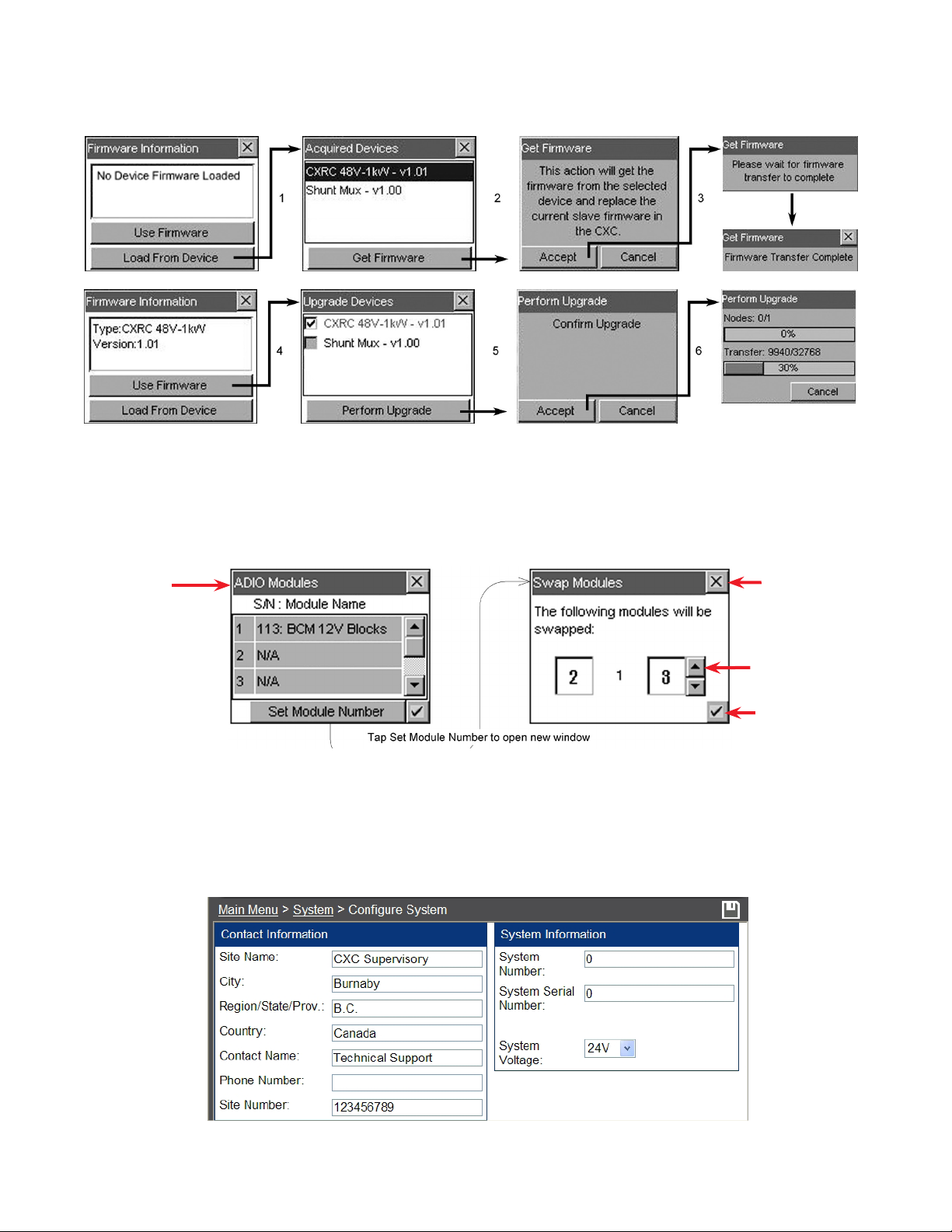
7. Repeat the steps above choosing Shunt MUX as required.
Figure 31 — Firmware upgrade procedure
6.1. 3 Set ADIO Module Number
The Supervisor can select and map the order number in which CAN-enabled system devices, such as
Battery Cell Monitor (BCM), are to appear in the CXC menus; shown in the examples below:
Select module
for mapping; e.g.
module 2
The module number
is important when any
of the signals from an
ADIO device is used for
custom signals or data
logging.
Figure 32 — ADIO Modules and Swap Modules windows
When replacing ADIO modules, assign the new identical device with the same ADIO module number of
the old device. This numbering preserves the functionality of any equations that use signals originating
on the old device.
6.1. 4 Site Information
Identical elds
exist in the LCD
for the entr y and
display of site
information.
Discard changes
and return to previous screen
Tap arrows to increase or decrease
value as required
Accept changes
and return to previous screen
0700015-J0 Rev B
1-888-462-7487
Figure 33 — Site Information and Contact Information windows – Web
37

6.1. 5 Temperature Units
This menu item enables the Supervisor to select the temperature display units (Celsius or Fahrenheit).
For the web interface, select Main Menu > Controller > Temperature Units.
Figure 34 — Temperature Units selection window
6.1. 6 Factory Information
The CXC factory unit default values are displayed here. Use the scroll bar to navigate the list of text items
for viewing; i.e., Unit Serial, Hardware Rev., Ethernet/MAC Address and Factory Notes.
For the web interface, select Main Menu > Controller > Factory Information.
6.1.7 User Inventory (Web Interface Only)
This page enables the user to enter data for up to 20 inventory items. When entering data, the tab key
may be used to move the cursor from one data entry box to the next. Figure 35 below:
Select from the pull-down menu
Accept change and return to previous screen
Figure 35 — User Inventory window (web interface only)
6.1. 8 System Inventory (Web Interface Only)
This page enables the user to view a single list of all CAN connected devices, user inventory items, and
battery information items. See Figure 36 below:
Select pull-down menu for
device details:
38
Figure 36 — System Inventory window (web interface only)
0700015-J0 Rev B

6.2 Converters
This menu category consists of converter alarms and controls. Parameters can be set/accessed such as
output voltage, OVP, high/low voltage alarms, and start delay.
The converter defaults are based on the system voltage of either 24 or 48 VDC.
At present, the converter software does not support:
• Two types of converters simultaneously
• 12, 125, and 220 VDC systems.
Other features include:
Active voltage control Inventory update
Converter locate Loadsharing
Firmware upgrade Major and minor alarms
6. 2.1 Converter Report
This feature provides the user with a list report (see 4. 7. 2 , Figure 17) of all acquired converters in the
system. The first column lists the serial numbers of the converters. The report then displays the output
current of each converter under the Amps column (or toggle for % of maximum output) and the number
of active alarms under the Alarms column (if that converter is issuing an alarm). The right most column
displays the number of settings out of tolerance.
Select a converter and tap View Details to produce another list showing details of the entire converter
alarms and settings that are out of tolerance.
6.2.2 Configure Settings
This feature allows the user to configure settings (via menu items) for all of the acquired converters in the
system; such as:
Output Voltage Start Delay
OVP Enable CL Alarm
Input Voltage Shutdown Input Voltage Restart
6.3 Rectifiers
This menu category consists of rectifier alarms and controls. Parameters can be set/accessed such as
float/equalize voltages, high/low voltage alarms, and start delay.
6.3 .1 Rectifier Report
This feature provides a list report (see 4 .7. 2 , Figure 17), of all acquired rectifiers in the system. The first
column lists the serial numbers of the rectifiers. The report then displays the output current of each rectifier under the Amps column (or toggle for % of maximum output) and the number of active alarms under
the Alarms column (if that rectifier is issuing an alarm). The right most column displays the number of
settings out of tolerance (OOT per web interface).
Select a rectifier and tap View Details to produce another list showing details of the entire rectifier alarms
and settings that are out of tolerance.
6.3.2 Configure Settings
This feature allows the user to configure settings (via menu items) for all of the acquired rectifiers in the
system.
0700015-J0 Rev B
39

Figure 37 — Configure Settings (rectifiers) window
The menu items described below can be configured via a virtual numeric keypad ( ) or by toggling the
listed item. For a basic programming example, see 4.7. 3.
6.3 .2.1 Float (FL) Voltage
The Supervisor can set the system BATTERY VOLTAGE (measured at an analog input channel) to the
desired float voltage value. Float voltage charges the battery string and supplies the load. Normally, the
power system will operate in the float mode. This setting should have a minimum of LVD + 1 V and a
maximum of OVP – 1 V.
6.3.2.2 Equalize (EQ) Voltage
The Supervisor can set the system BATTERY VOLTAGE (measured at an analog input channel) to the desired equalize voltage value. Equalize voltage charges the battery string at a higher than normal voltage
to either recharge batteries after a power failure or to balance individual cell voltages. Periodic equalizing
of the battery string may be required to optimize battery performance and life. This setting should have a
minimum of LVD + 1 V and a maximum of OVP – 1 V.
Discard changes and return to
previous screen
Sliders and scroll bars are used
for navigation Select menu item to
congure
Accept changes and return to
previous screen
6.3.2.3 Battery Test (BT) Voltage
The Supervisor can set the Battery (Discharge) Test Voltage to the desired value during the test (mode).
This setting should have a minimum of LVD + 1 V.
6.3.2.4 Safe Voltage
The Supervisor can set the default system voltage (Safe Mode) in the event that communications to Cordex rectifiers should fail. See 2.5 for more details about this feature.
6.3.2.5 OVP Voltage
The Supervisor can program one OVP setting for all connected rectifiers. OVP will disable a rectifier that
outputs an abnormally high voltage.
6.3.2.6 Low Voltage Alarm (LVA)
The Supervisor can program one LVA setting for all connected rectifiers. LVA serves as a warning to the
user indicating that output voltage is dropping.
6.3.2.7 High Voltage Alarm (HVA)
The Supervisor can program one HVA setting for all connected rectifiers.
HVA serves as a warning to the user indicating that output voltage is rising. This value should be less
than the OVP setting in order for the HVA to work effectively.
6.3.2.8 Current Limit (CL)
This menu item sets the level as a percentage at which current limiting activates in all connected rectifiers. Current limiting is a primary response to output over current situations. If the output current on the
rectifiers exceeds the current limit setting, their output voltage will automatically decrease but will maintain the current output at the current limit level. This prevents potential damage to the rectifiers.
If the CXC finds rectifiers in the system that cannot meet the default current limit value, the CXC will correct its default limit setting to match the rectifiers.
40
0700015-J0 Rev B

6.3.2.9 Power Limit (PL)
This menu item sets the level as a percentage at which power limiting activates in all connected Cordex
rectifiers.
6.3 .2.10 EQ Timeout
This menu item controls the maximum equalize time setting for all connected rectifiers. This control is
designed to prevent accidental over-charge of the batteries. CXC will send the command to change the
equalize time-out setting in all the rectifiers.
6.3. 2.11 BT Timeout
This menu item controls the maximum duration of the Battery Test.
6.3 .2.12 Slope (Pathfinder rectifiers only)
This menu item sets all connected rectifiers to the same slope adjustment value. Slope determines the
regulation percentage of the current between rectifiers in a group. When load sharing is initialized, CXC
will send commands to the rectifiers to try to adjust their output voltage within this slope range. The rectifiers should have their output voltage as close to being equal, in order to balance (or share) the load
current between them.
6.3 .2.13 Backlight Timeout (Pathfinder rectifiers w/LCD only)
This menu item controls the amount of time of GUI inactivity permitted before the rectifier automatically
turns off the LCD backlight.
6.3 .2.14 Security Code (Pathfinder rectifiers w/LCD only)
The Supervisor can program one security access code for all connected rectifiers. CXC logs in each of
the rectifiers as Factory Access and sends the direct command to change the access code.
6.3 .2.15 Module Start Delay
This menu item controls the stagger-start timer for all connected rectifiers.
With start delay, rectifiers start up in a time-delayed sequence. This prevents excessive loading of the
AC source. For example, setting a start delay time of 5 seconds will cause rectifier#1 to start at 1 second, rectifier#2 at 5 seconds, rectifier#3 at 10 seconds, etc. In the case where the start delay exceeds
the maximum range, the next rectifier in sequence will start its delay at zero and increment again by the
value specified in this menu item.
When the rectifier Module Start Delay is set to 0 s, all the rectifiers start with a 0 sec delay.
6.3 .2.16 System Start Delay
This menu item controls the amount of time, in seconds, before the stagger-start timer commences, see
the previous section.
6.3 .2.17 Soft Start Ramp Rate (Cordex rectifiers only)
The Supervisor can select the soft start ramp rate (normal or fast). Current limit ramps up at about
t12%/sec during normal soft start and 100%/sec during fast.
For systems without batteries, select the Fast setting for the Soft Start Ramp Rate.
6.3 .2.18 Temp Display Scale (Pathfinder rectifiers w/LCD only)
The Supervisor can select the temperature display scale (Celsius or Fahrenheit).
6.3 .2.19 Check to Enable
The Supervisor can toggle (enable or disable) the following list of items:
• CL and PL Alarm
• Remote Shutdown (Cordex rectifiers only; affects operation of Power Save, see below)
• Local Access Alarm (Pathfinder rectifiers w/LCD only)
• Ramp Test (Cordex rectifiers only)
0700015-J0 Rev B
41
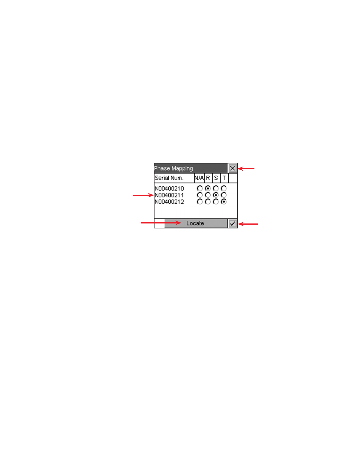
6.3.3 Power Save
The Supervisor can improve operational efficiency when conditions warrant by running only the necessary number of rectifiers. The remote shutdown setting (enable or disable) affects correct operation of the
Power Save feature. See also 2.6 for more details.
6.3.3.1 Enable
The Supervisor can control the CXC Power Save feature.
6.3.3.2 Redundant Rectifiers
The Supervisor can specify the number of extra rectifiers to turn on.
6.3.3.3 Max (Maximum) Power Usage
The Supervisor can specify the percentage (of maximum power usage) per rectifier module used in the
computation of the Power Save feature. This works to avoid rectifiers operating continuously at greater
than the set limit (i.e. 95%) and going into current limit frequently due to load surges or power limit conditions; such as, low line voltage or high temperature.
6.3.3.4 Phase Mapping
The user can assign or map a rectifier per input signal for individual phase voltage readings:
Assign/map a rectier per Phase R, S, and T
(radio buttons) for the respective signal
Discard changes and return to
previous screen
Tap Locate and the LEDs of the selected rectier
will ash to enable the user to determine the phase
connection
Accept changes and return to
previous screen
Figure 38 — Phase Mapping (rectifiers) window
42
0700015-J0 Rev B
 Loading…
- No category
Cordex™ CXCR 125/220V
Download
Report
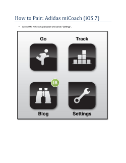
How to Pair: Adidas miCoach (iOS 7)
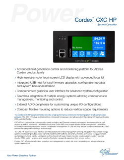
Alpha Cordex™ CXC HP-System Controller
PTI — 3P — ppiindia.net

Poskom PXM-20BTP
DHC BT 2010

Specification Sheet — Global Technology Systems
![Era Series [Innovative] [F] [Converted].ai - dtp.co.th](https://s3.expydoc.com/store/data/000606526_1-addfffaacb444e21fda50388de95ea70-250x500.png)
Era Series [Innovative] [F] [Converted].ai — dtp.co.th

Summer 2014 — Hawker Battery | EnerSys
FG20341 12 Volt 3.4 Ah FG series
TRITON – M2
S-HJT/3/3W c/w LED/40/NL — No Lens (Wide Angle) S
Open — The Scottish Government
expydoc.com
- Explore
- Sitemap
- About ExpyDoc
- Contacts
Your ExpyDoc
- Log in
- Create new account
© Copyright 2023 ExpyDoc
- About ExpyDoc
- DMCA / GDPR
- Report