*Производитель оставляет за собой право без уведомления
менять характеристики, внешний вид, комплектацию товара.
Указанная информация не является публичной офертой.

Бесплатная доставка до транспортной компании

Собственный сервисный центр

- Описание
- Доставка
- Задать вопрос
Доставка
Компания ООО «ПКФ УРАЛКРАНДЕТАЛЬ» предлагает несколько вариантов доставки товаров:
-
Бесплатная доставка до терминала ТК Деловые линии (меж терминальная доставка и доставка до склада Покупателя, оплачивается отдельно)
-
Доставка товара до склада Покупателя (отправка производится ТК Деловые линии, необходимо запросить выставить счет на Товар, с учетом доставки до склада Покупателя).
-
Доставка по г. Екатеринбург, автотранспортом ООО «ПКФ УРАЛКРАНДЕТАЛЬ» (необходимо запросить счет на Товар, с учетом доставки).
-
Самовывоз со склада.
Для получения товара транспортной компанией Покупателя, необходимо заполнить и прислать Доверительное письмо.
Задать вопрос
Вы можете задать любой интересующий вас вопрос по товару или работе магазина.
Наши квалифицированные специалисты обязательно вам помогут.
Задать вопрос
1 INSTALLATION & OPERATION MANUAL saga1 -L Series 1 SAGA 1-L10/L12 User s MANUAL Table Of Contents Chapter 1 Warranty 1-1 Warranty 1-2 Warranty Period 1-3 Excluded Items 1-4 Remarks Chapter 2 Operating Precautions 2-1 Attention 2-2 Precautions 2-3 Emergency Procedures Chapter 3 Standard Accessories Chapter 4 OPERATION 4-1 Transmitter Configuration 4-2 General OPERATION 4-3 Special Functions OPERATION 4-4 The Use of Copier 4-5 Change of Frequency 4-6 ID-Code Remote Setting 4-7 Receiver Voltage Selection 4-8 Transmitter Battery Adoption Appendix: I. Function Setting (Defined by Customer) II. Correspondence Between Pushbuttons and Relay Output III PC Software INSTALLATION and OPERATION Guide IV Additional Applications V General Specification saga1 -L Series 2 Chapter 1 Warranty 1 — 1 Warranty Gain Electronic Co.
2 , Ltd. guarantees that this equipment meets its published it should work as expected. However, GAIN does not guarantee that OPERATION in saga1 system is error free or without intermission. 1 — 2 Warranty Period This equipment is warranted against defects in material and manufacturing for a period of one year from the date of shipment. During the warranty period, GAIN is responsible for necessary repairs as long as the product can be proved to be defective. For warranty service or repair, this product must be returned to a service facility designated by GAIN. Buyer will pay shipping charges to GAIN, while GAIN will pay return shipping charges. 1 3 Excluded Items This warranty does not include consumptive parts such as batteries, fuses, buttons, and relays. Also this warranty does not cover defects caused by improper INSTALLATION , improper or insufficient maintenance, unauthorized modification, improper OPERATION , ignorance of environmental specifications, or improper software or interfacing.
3 1 — 4 Remarks 1. No other warranty is expressed or implied, except for the above mentioned. 2. The remedies provided herein are the buyers sole and exclusive remedies. GAIN shall not be liable for any direct, indirect, special, incidental or consequential damages. saga1 -L Series 3 Chapter 2 Operating Precautions 2 — 1 Attention 1. Read this MANUAL carefully before operating and installing saga1 -L10/L12. 2. Due to the complex nature of equipment, it is necessary to read the entire MANUAL before INSTALLATION . 3. Never allow any unauthorized personnel to dismantle equipment as this may cause the equipment to be damaged. 4. The equipment has been stringently tested for quality before delivery from our plant. However, it must not be used in extremely dangerous situations, or where damage may result. 5. After operating the Crane, switch off main power as well as the power on the Receiver and remove the Transmitter key.
4 6. The Transmitter should be safely placed when not in use to avoid accidental pressing of buttons. 7. The Crane should be equipped with a main power Relay, Limit Switch and other required safety devices. 8. Don’t use this device during electrical storm or where there are conditions of high electrical interference. 9. Ensure that the Transmitter batteries are in good condition and the power for Receiver is normal. 10. INSTALLATION and maintenance should be done only while the Crane’s main power is off and the Receiver s power is off to prevent electrical shock. 11. The contents of the MANUAL may be amended by the manufacturer without notice. 12. The manufacturer may introduce new functions to the equipment as is necessary; therefore, the descriptions may be subject to change. 2 — 2 Precautions 1. After operating saga1 -L10/L12, please press EMS mushroom and shut off the main power supply on the Crane & the Receiver and remove the Transmitter key.
5 2. Stop operating when slow-response occurs due to insufficient Transmitter power, beyond the remote control range or severe interference. 3. Remove the batteries when the equipment is not going to be in use for a long period of time. saga1 -L Series 44. SAGA is suitable for use in diverse industrial environments correct operating and maintenance will extend the saga1 system s life. 5. Check EMS mushroom and the other security functions of the saga1 system before daily OPERATION . 6. Presses EMS mushroom when malfunctions or abnormal conditions occur. 7. The operator must be familiar with the following Emergency Procedures before operating. 2 — 3 Emergency Procedures In case of emergency, please follow the steps below: 1. Press EMS mushroom. 2. Turn the security key or rotary key switch to «OFF» position. 3.
6 Remove the battery box and key. 4. Shut off the main power of the Crane and discontinue the OPERATION . 5. Contact the distributor to find out reasons. saga1 -L Series 5 Chapter 3 Standard Accessories A standard and full set of saga1 -L10/L12 is consist of: Transmitter ( strap included ) — 1 unit Receiver — 1 unit Transmitter ( strap included ) — 1 unit Receiver — 1 unit saga1 -L12 saga1 -L10 saga1 -L Series 6 Chapter 4 OPERATION 4 1 Transmitter Configuration saga1 -L10 saga1 -L12 Figure 4-1 Transmitter Configuration 1- Antenna 6- F1 Pushbutton 2- Emergency Stop 7- Start Pushbutton 3- LED Indicator 8- Battery Cover 4- Motion Pushbutton 9- Rotary Key Switch 5- Aux. Pushbutton R1 ~ R4 10-Security Key 15 4 2 8 5 9 3 7 5 6 4 2 1 4 5 3 4 10 saga1 -L Series 74 2 General OPERATION 1.
7 Install 2 new AA-size alkaline batteries in the battery box of saga1 -L12, then insert into battery case of transmitter; or battery chamber of saga1 -L10, and screw up transmitter s bottom cover. Make sure the + and — directions are correct.. 2. Insert security key in the OFF position. 3. Turn on the power according to the Power-On Modes . Note: LED indicator will flash with red color if proper procedures are not followed. 4. Operate transmitter by pressing each pushbutton. 5. After OPERATION , perform the following procedures in sequence: (1) Press EMS mushroom, (2) rotate security key or rotary key switch counterclockwise to the OFF position, (3) remove key and keep it in a safe place, (4) remove batteries if not to be used for a long period of time. 4 3 Special Functions OPERATION 4-3-1 Power-On operations Power-on means that the Main-Relay on the receiver will switch on as soon as the transmitter sends a signal and then the receiver will be on standby for continuous control.
8 There are 2 options for Power-On Mode : A. Any pushbutton Power-On Mode 1. Rotate EMS mushroom clockwise 45 and pull out. 2. Turn security key clockwise to ON position for saga1 -L12; Rotary key switch clockwise to ON position for saga1 -L10. 3. Press any pushbutton on the transmitter. This will turn on the power as well as execute the function of pushbutton. B. Start pushbutton Power-On Mode 1. Rotate EMS mushroom clockwise 45 and pull out. 2. Turn security key clockwise to ON position for saga1 -L12; Rotary key switch clockwise to ON position for saga1 -L10. 3. Press Start pushbutton on the transmitter to turn on power for saga1 -L12; Continue to turn rotary key switch to START position to turn on power for saga1 -L10(the rotary key switch will return to ON position saga1 -L Series 8automatically after been released).
9 4-3-2 Acceleration OPERATION 1. For saga1 -L12 : Start pushbutton is the acceleration pushbutton. 2. For saga1 -L10 : Start key is the acceleration key to use. 3. When a motion is in the second speed, quick touch of acceleration pushbutton will accelerate the speed. Repeated touch of acceleration pushbutton will increase the speed. Note: When accelerating, the motion pushbutton must be depressed and held in the second speed. If motion pushbutton is released, there will be no acceleration and speed will return to zero. 4-3-3 Inching OPERATION 1. Start pushbutton(or key) is set for inching function. 2. Press or turn and hold inching pushbutton or key. 3. Press any motion pushbutton to perform the inching motion. Note: The other pushbutton of transmitter must be released before press inching pushbutton. 4 4 The Use of Copier 1. Insert the six pins female plug of copier into the male socket inside the TX or RX of saga1 -L10/L12. 2.
10 For copying and saving the data from TX or RX, put on the magnetic key onto the receptor to connect; for transferring the saved data from copier to TX or RX, release the magnetic key from the receptor. 3. Press and release 1 pushbutton (or 2, 3) to copy and save the data (When magnetic key is on) from TX or RX, after the green indicator light has flashed, the transfer is finished, disconnect the plug. Proceed the same procedure to transfer the data from copier to TX or RX. (When magnetic key is off) Note: sure the power of TX or RX is off when copying. copier for saga1 -L10/L12 (dual colors on the appearance) can also be used for existing saga1 -L4/6/8/6B/8B, the old one (blue) can not be used for saga1 -L10/L12. copier can copy both function settings and ID-Code, but to pair the crystal is still essential to match both TX and RX for communicating each other.
 |
[Page 1] Saga SAGA1-L Series INSTALLATION & OPERATION MANUAL |
 |
[Page 2] Saga SAGA1-L Series SAGA1-L Series 1 SAGA 1-L10/L12 User’s Manual Table Of Contents Chapter 1 Warranty 1-1 Warranty 1-2 Warranty P… |
 |
[Page 3] Saga SAGA1-L Series SAGA1-L Series 2 Chapter 1 Warranty 1 — 1 Warranty Gain Electronic Co., Ltd. guarantees that this equipment meets its publ… |
 |
[Page 4] Saga SAGA1-L Series SAGA1-L Series 3 Chapter 2 Operating Precautions 2 — 1 Attention 1. Read this manual carefully before operating and install… |
 |
[Page 5] Saga SAGA1-L Series SAGA1-L Series 4 4. SAGA is suitable for use in diverse industrial environments correct operating and maintenance will extend… |
 |
[Page 6] Saga SAGA1-L Series SAGA1-L Series 5 Chapter 3 Standard Accessories A standard and full set of SAGA1-L10/L12 is consist of: Transmitter ( strap… |
 |
[Page 7] Saga SAGA1-L Series SAGA1-L Series 6 Chapter 4 Operation 4 – 1 Transmitter Configuration SAGA1-L10 SAGA1-L12 Figur… |
 |
[Page 8] Saga SAGA1-L Series SAGA1-L Series 7 4 – 2 General Operation 1. Install 2 new AA-size alkaline batteries in the battery box of SAGA1-L12, then ins… |
 |
[Page 9] Saga SAGA1-L Series SAGA1-L Series 8 automatically after been released). 4-3-2 Acceleration Operation 1. For SAGA1-L12 : “Start” pushbutton is th… |
 |
[Page 10] Saga SAGA1-L Series SAGA1-L Series 9 4 – 5 Change of Frequency It is easy to change frequency of the SAGA1-L series simply by replacing … |
 |
[Page 11] Saga SAGA1-L Series SAGA1-L Series 10 4 – 6 ID-Code Remote Setting ID-Code remote setting allows you to pair the new TX or RX if one of them is dam… |
 |
[Page 12] Saga SAGA1-L Series SAGA1-L Series 11 4 – 7 Receiver Voltage Selection There are two types of power vo… |
 |
[Page 13] Saga SAGA1-L Series SAGA1-L Series 12 APPENDIX I Function Setting (Defined by Customer) 1. Pushbutton Function setting: 1-1.“UP/DOWN”, ”EAST/WE… |
 |
[Page 14] Saga SAGA1-L Series SAGA1-L Series 13 3 EMS Control 1. Ctrl. by EMS 2. Bypass EMS Control by EMS: means the corresponding relay of function … |
 |
[Page 15] Saga SAGA1-L Series SAGA1-L Series 14 2. Transmitter Function Setting: Item Title Content Description 1 Power-On Mode 1. Any Pushbutton 2. Start… |
 |
[Page 16] Saga SAGA1-L Series SAGA1-L Series 15 6 Remote Setting 1. Enable 2. Disable Enable: Allow the transmitter to do ID- Code remote setting. Disa… |
 |
[Page 17] Saga SAGA1-L Series SAGA1-L Series 16 APPENDIX II Correspondence Between Pushbutton and Relay Output All SAGA1-L12 is equipped with 4 relays in e… |
 |
[Page 18] Saga SAGA1-L Series SAGA1-L Series 17 6.Dual Motor(2)/Dual Motor(2) 1 st Step 2 nd Step 1 st Step … |
 |
[Page 19] Saga SAGA1-L Series SAGA1-L Series 18 APPENDIX III PC Software Installation and Operation Guide 1. Software Installation: 1-1. Open CD-Rom of your co… |
 |
[Page 20] Saga SAGA1-L Series SAGA1-L Series 19 1-3. Click “Finish” to end the installation, then remove the CD from the CD-Rom. The program will add a sho… |
 |
[Page 21] Saga SAGA1-L Series SAGA1-L Series 20 2-2. Default and second page of the program: … |
 |
[Page 22] Saga SAGA1-L Series SAGA1-L Series 21 2-3. Using RS232 connecting cable to connect transmitter or receiver to the computer, click “Read Data”… |
 |
[Page 23] Saga SAGA1-L Series SAGA1-L Series 22 2-5. To read data from saved file, click “Open File”, after the source file (*.saga) chosen, click “O… |
 |
[Page 24] Saga SAGA1-L Series SAGA1-L Series 23 APPENDIX IV Additional Applications 1.Exchangeable NC/NO Relays: There are reserved NC/NO output contacts for… |
 |
[Page 25] Saga SAGA1-L Series SAGA1-L Series 24 APPENDIX V General Specification Frequen… |


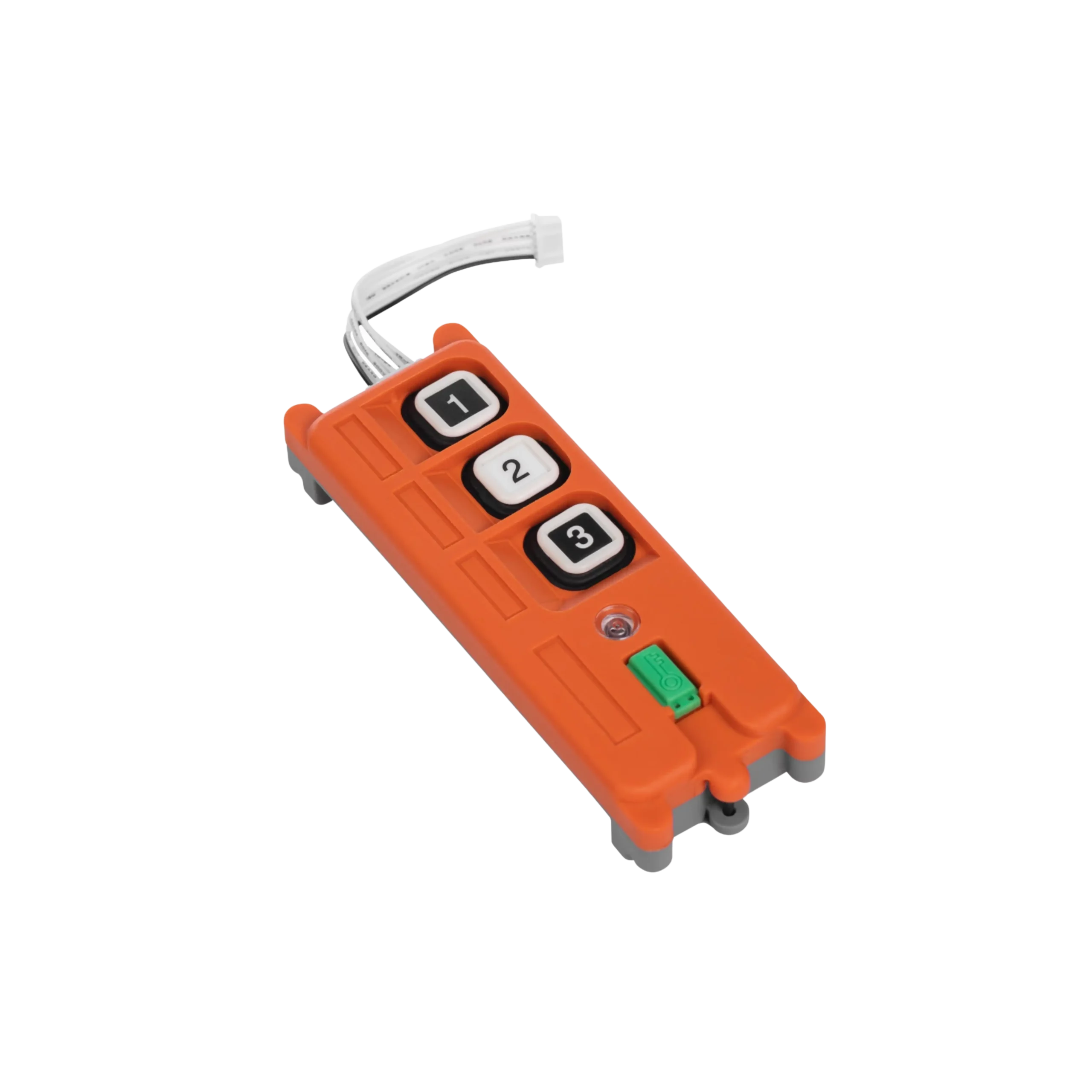
- The SAGA1 K series copier can synchronize (pair) transmitters and receivers without a computer.
- SAGA1 K series duplicators are suitable for SAGA1-K1/K2 and SAGA1-K3/K4 products.
SAGA1-K1/K2 , SAGA1-K3/K4
Follow us:”Facebook: Telecrane Taiwan”,“ Youtube: Telecrane Taiwan”

Category: SAGA1 Accessories
Tags: SAGA1-K1/K2, SAGA1-K3/K4
You may also like…
-

SAGA1 AccessoriesSAGA1 L Series Copier