
Order code: IC-NT MINT, IC-NT MINT LT
This product is discontinued. Contact ComAp local representative for availability.
Gen-set controller for gen-sets in multiple parallel applications.
- Overview
- Related products
- Resources
- Overview
- Related products
- Resources
InteliCompact NT MINT (RFA) offers:
- Compact genset controller for gensets operating in multiple island and/or parallel to mains mode (together with MainsCompact NT)
- Advanced Power Management for up to 32 gensets allowing
Load demand Start/Stop function
Load demand Swapping of different size gensets
Running Hours equalization - Active Load and VAr sharing
- Full gen-set monitoring and protection
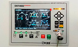
- Possibility to connect up to 8 gauges to display engine values
- True voltage and current RMS measurement
- Outstanding EFI engine support (CAN/J1939, RS232/Modbus) with diagnostic messages in plain text
- 3 phase generator voltage and current measurement
- 3 phase busbar voltage measurement
- 3 phase power measurement
- 3 analog inputs
- RS232, RS485, USB, Modbus, GSM/Analog Modem, Internet communication*
- GPRS communication and IC-NT RD (remote display) software
- AirGate and WebSupervisor support
- Support of active SMS Events or Commands
- Event and performance log
- 2 languages (user changeable)
* Relevant plug-in module is required
* FW version IC-NT 2.5.0 or newer is needed for the compatibility of Load Sharing and Power Management with InteliGen 200
Related products
Accessories
Frequently Asked Questions
Can I unlock my controller?
If you have forgotten your controller password, it can be found using the password decode function.
You will need the following information about your device:
- serial number
- «password decode» number
Both numbers can be obtained through the monitoring software relevant to the device.
- Serial number is available in Controller info
- Password decode number is available in Values / Info
You can also show these numbers on your device’s display. Typically, this requires a sequence or combination of buttons to be pressed. Details can be found typically in the device Operator guide.
Once you have these numbers, please contact your ComAp distributor and they will help you get your password back.
I cannot program my controller, it looks dead. How do I restore a controller with broken firmware?
The controller firmware does not usually break by itself however it can be damaged during controller programming, typically if power is lost during the process. If there does not seem to be a hardware issue with the controller there is an option to restore the controller using a process called ‘Boot Jumper’ programming.
This can be described as a sequence of steps you need to perform to allow the configuration tool to write new firmware into the device.
The steps typically are:
- Physically connect the controller to your PC.
- Power the controller on and initiate connection and firmware programming from the software tool menu.
- The software will ask you to switch the device off, close the Boot Jumper and switch the device back on.
- The programming will then proceed and you will receive further instructions during the process.
The boot jumper can be found either on the communication module (where plug-in modules are used) or on the device itself, typically under a rubber grommet, next to the dongle slot.
The description above is not enough? Try our Booot jumper training video.
How do I connect to my ComAp controller? What types of connections are supported?
ComAp offers a wide range of options to connect to your controller:
- RS232 / RS485
- USB — USB A<->B (usually a printer cable)
- Internet connection — LAN, GPRS, 3G, 4G
Note that some connection types require you to use a communication module (plug-in eg a RS232 card) or communication bridge (external device eg Internet Bridge NT).
Each ComAp device usually allows for multiple ways of connection. The simplest one supported by the majority of our devices is the RS232 (serial) connection. For this, you need an RS232 cable (null modem) and if your PC is not equipped with an RS232 port you need a USB<->RS232 converter.
USB connections are very common. Almost all ComAp devices support connection using simple USB A<->B cable (printer cable) for easy configuration. Some devices can be powered from the USB port for programming to allow easy configuration right on your desk.
Other connection types: Internet connection (LAN, GPRS, 3G, 4G), Modbus RTU, Modbus TCP, SNMP, AirGate, Modem.
Note that some connection types require you to use a communication module (plug-in eg a RS232 card) or communication bridge (external device eg Internet Bridge NT). Not all types of connection are possible on each device. You can find all the details related to this topic in your device’s Comprehensive guide or Communication guide.
Detailed information about connection to:
InteliLite NT, InteliATS NT, InteliCompact NT is available IL-NT, IA-NT, IC-NT Communication Guide (page 21)
InteliGen-NT, InteliSys-NT, InteliMains-NT is available in IGS-NT Communication Guide (page 19)
InteliLite is available in Global Guide InteliLite AMF25 Global Guide (page 126)
I cannot connect to my controller using the Internet or AirGate connection, why?
Usually connecting to the controller over the internet is straightforward and works out of the box. However, there are a few parameters that need to be set correctly.
- Make sure you have the latest firmware in the controller itself but also in all the communication modules (plug-in, built-in or external).
- Communication modules that supports connection via the internet
- CM-4G-GPS
- CM-Ethernet
- CM-GPRS
- InternetBridge-NT 4G
- InternetBridge-NT
- IB-Lite
- IB-COM (Built-in communication module for NTC controllers)
- IL-NT GPRS
- Communication modules that supports connection via the internet
- Ensure the communication interface is configured correctly.
- CM-4G-GPS, CM-Ethernet, CM-GPRS — Can be set in the controllers setpoints on the unit itself or using InteliConfig configuration software.
- IB-COM, IB-Lite — Use web interface — just connect to http://<controller-ip-address>/sp_index.htm using your favourite web browser.
- InternetBridge-NT 4G, InternetBridge-NT — Requires a software tool called IBNTConfig(https://www.comap-control.com/products/detail/ib-nt-config) and an USB A<->B cable for configuration. This way you can also enable MODBUS, SNMP etc.
- Make sure there is no firewall blocking your connection. Consult your IT specialist or ISP if not sure. If you use a firewall, make sure the following ports are open for communication:
- The device must be able to send data to the AirGate server at UDP port 6127 and TCP port 23. The TCP port can be changed in the module setup to 21 if needed.
- TCP port 44445 is required for WebSupervisor connection.
- Port 80 is used for accessing the communication module web interface.
- Port 502 is used for Modbus TCP communication (enabled by default).
- Port 161 is used for SNMP (needs to be enabled).
How do I change the controller firmware? Where can I get the latest firmware?
You can download the latest firmware package on the webpage of the device. You can easily navigate there through the ‘Products’ section or just use the Search function. If you cannot find the firmware on the website or if you require different than the offered version do not hesitate to contact our support team.
The firmware upgrade itself is easy to perform. You need the appropriate configuration software and a connection to the controller (preferably a direct connection). Prior to initiating the update process, we strongly recommend you to save a complete backup of your device.
It usually consists of several steps:
- Create a controller back up.
- Update the device firmware. It will contain default Configuration Archive and default Application.
- Change the Application (SPtM, MiNT, MCB, MGCB, BTB, etc) to the required type (by programming appropriate default archive to the controller).
- Use the Import Configuration Wizard to restore your previous configuration. In some cases manual interventions might be needed during this step.
- Optional: Update the connected display firmware or device communication module firmware.
Should you be unsuccessful in programming the new version, the rollback procedure is to install previous firmware version and use your back up to restore the controller to its original state before the firmware upgrade was attempted.
You might also need
Alternative products from the category
Our website uses cookies and similar technologies to provide you the best experience and to understand how you use our site.
You may either „Accept all“ by which you agree with using functional, analytical and marketing cookies. By pressing „Revoke“ only necessary cookies shall be allowed to enable the website and applications function correctly. To revoke your consent you can do it from footer menu in Change cookie preferences section.
You can find more information on the Cookie page and the Privacy section .

Поставка под заказ 2-3 недели
Контроллер ComAp InteliCompact NT MINT
-
Характеристики
-
Услуги
-
Документация
-
Отзывы
Характеристики
| Производитель: | ComAp |
| Происхождение бренда:
? |
|
| Автозапуск: | нет |
| Параллельная работа: | да |
| Параллельная работа: | нет |
| PLC: | нет |
| USB разъем: | нет |
| ЖК экран: | LCD экран с LED подсветкой пиктограмм |
| WiFi: | нет |
| RS232 (com): | да |
| CAN-шина: | да |
| Ethernet (LAN):
|
да |
| RS485: | нет |
| Журнал событий: | да |
| Габариты: | 185x125x58 |
| Размер выреза в панели: | 168×110 |
Услуги
Наша мобильная служба сервиса работает по всей территории Российской Федерации и может предложить вам следующие работы, связанные панелями управления (контроллерами) генераторных установок:
Для заказчиков, которых не устраивает существующая панель управления генераторной установки, сотрудники службы сервиса нашей компании готовы провести полный комплекс работ по замене, настройке и наладке контрольных панелей и пультов управления любых генераторов. При производстве этих работ на уже установленную дизельную электростанцию могут быть добавлены дополнительные функции и возможности.
Синхронизация генераторов успешно используется в ситуациях, когда необходимо обеспечить совместную параллельную работу двух или более генераторов. Данное решение может применяться для решения самых разнообразных задач. Специалисты нашей компании готовы наладить синхронную работу любых генераторов, как уже купленных, так и только планируемых к приобретению. Мы обеспечиваем параллель как для однотипных генераторов, так и для генераторов разных марок и\или мощностей.

Для идущих в ногу со временем владельцев генераторных установок, сервисная служба «Мототех» предлагает новое современное решение в области удаленного WEB и GSM мониторинга. Мы предлагаем мониторинг, который работает с любыми генераторными установками и электростанциями. Каждый клиент найдёт для себя решение, максимально полно отвечающее его потребностям и техническим особенностям объекта.
Ресурс любого оборудования не вечен. Квалифицированное и регулярное техническое обслуживание позволит продлить срок эксплуатации, но не может гарантировать отсутствие каких либо поломок. В таких ситуациях для заказчика наиболее важно обратиться именно в профессиональную инжиниринговую компанию, которая проводит ремонты оборудования (в нашем случае электростанций и дизельных генераторов) на постоянной основе, регулярно осуществляя эти работы и имея за плечами многолетний опыт. Сервисная служба нашей компании выполняет ремонт любых дизельных генераторов.
Документация
- Каталог контроллеров Comap
- Спецификации на панель управления ComAp InteliCompact NT MINT
- Руководство пользователя для пульта управления ComAp InteliCompact NT MINT
2424000990242400 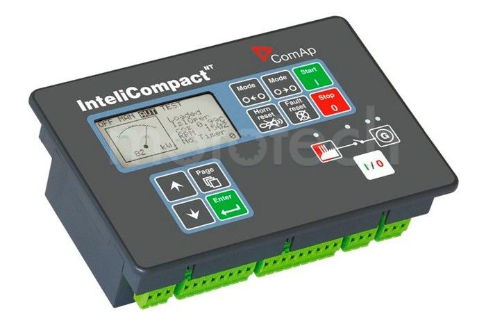
Купить Контроллер ComAp InteliCompact NT MINT производства Чехия гарантия . Подробные технические характеристики, фотографии, цены
Описание ComAp InteliCompact NT MINT
Панель управления ComAP InteliCompactNT MINT является встраиваемым (устанавливаемым) контроллером для одиночных генераторных установок. Контроллер полностью подходят для управления генераторной установкой, которая работает в резервном режиме и имеет АВР (автомат ввода резерва), включая управление электростанцией по модему, настройку пользователем, полный контроль и защиту генераторных установок.
- Поддержка по работе с двигателем с электронным впрыском топлива (стандарт J1939, Modbus);
- Базовая нагрузка, Импорт/Экспорт, Срез пиков, Управление напряжением и коэффициентом мощности
- Работа в параллель до 32 установок
- Работа в режиме АВР
- Встроенные ПЛК функции
- Конфигурируемые входы/выходы для различных нужд потребителя
- Журнал событий (до 500 записей)
Обзор марки ComAp
Наши преимущества
С 2001 на рынке
Мы успешно реализуем энергетические решения уже 20 лет и накопили опыт решения самых сложных задач
Сервисная служба
Мы обладаем собственной мобильной службой сервиса и ремонта оборудования
Большой склад
Наш склад — это более тысячи наименований оригинальных запчастей и различных расходных элементов
Гарантия качества
Все наши решения защищены и проверены одной из крупнейших СРО. Ответственность застрахована
Аналоги по техническим параметрам ComAp InteliCompact NT MINT

По запросуЗапросить
- Автозапуск: нет
- Параллельная работа: нет
- CAN-шина: нет
- RS485: нет
- Журнал событий: да

По запросуЗапросить
- Параллельная работа: нет
- CAN-шина: нет
- RS485: нет
- Журнал событий: нет

По запросуЗапросить
- Автозапуск: нет
- Параллельная работа: нет
- CAN-шина: нет
- RS485: нет
- Журнал событий: нет

По запросуЗапросить
- Автозапуск: да
- Параллельная работа: нет
- CAN-шина: нет
- RS485: да
- Журнал событий: нет
В избранноеСравнить
\"")
Цену и наличие уточняйте у менеджеров
InteliCompact MINT являются встраиваемыми контроллерами генераторных установок для применения в дежурном режиме и режиме параллельной работы.Оптимизированы для простого использования, установки и настройки; включают в себя встроенный синхронизатор и цифровое изохронное разделение нагрузки. Контроллеры обеспечивают работу до 32 генераторных установок в параллель.
Для подключения к ПК нужен дополнительный модуль — IL-NT S-USB.
Купить в 1 клик
- Описание
- Характеристики
- Фотографии
- Инструкция
- Доставка
- Другие товары данной категории
- Отзывы
InteliCompact IC-NT-MINT являются встраиваемыми контроллерами генераторных установок для применения в дежурном режиме и режиме параллельной работы.Оптимизированы для простого использования, установки и настройки; включают в себя встроенный синхронизатор и цифровое изохронное разделение нагрузки. Контроллеры обеспечивают работу до 32 генераторных установок в параллель.
Основные технические параметры InteliCompac NT MINT, IC-NT-MINT:
- Функции АВР и параллельной работы;
- Срез пиков, Сетевой экспорт/импорт;
- Поддержка по работе с двигателем с электронным впрыском топлива (стандарт J1939, Modbus); отражение кодов тревог в текстовой форме;
- Базовая нагрузка, деление нагрузки;
- Оптимизирование количества работающих генераторных установок в режиме параллельной работы;
- Конфигурируемые входы/выходы для различных нужд потребителя;
- Файл истории.
| Размеры ДxШxВ, мм | 180x120x55 |
| Вес, г | 450 |
Самовывоз
Офис: г. Санкт-Петербург, ул. Литовская, д. 10.
Режим работы: Пн — Пт с 9:00 до 18:00.
Склад: г. Санкт-Петербург, ул. Латышских стрелков, д. 31
Режим работы: Пн — Пт с 10:00 до 17:00.
Доставка по России
Осуществляется транспортными компаниями и курьерскими службами.
Рассчитать стоимость доставки
Отзывы о Контроллер ComAp InteliCompact NT MINT (IC-NT MINT)
Отзывов еще нет.
Будьте первым, кто оставить отзыв!
-
7/26/2019 Comap Igs Nt Mint 2.2 Reference Guide
1/102
Copyright 2005 ComAp s.r.o.
ComAp, spol. s r.o.Kundratka 2359/17, 180 00 Praha 8, Czech
RepublicTel: +420 266 012 111, Fax: +420 266 316 647Technical support
hotline: +420 266 012 666E-mail: [email protected], www.comap.cz
REFERENCE GUIDE
Compact Controller for Stand-by and Parallel Operating
Gen-setsInteli New Technology
Modular Gen-set ControllerMultiple Internal engines application
SW configurationMINT
IG-NT, IG-NTC, IG-EE, IG-EEC, IS-NT
Software version IGS-NT-2.2, December 2007
-
7/26/2019 Comap Igs Nt Mint 2.2 Reference Guide
2/102
Inteli NT MINT, SW Version 2.2, ComAp December
2007IGS-NT-MINT-2.2-Reference Guide.PDF2
Table of Contents
Table of Contents
……………………………………………………………………………………………………………………………..2General
guidelines…………………………………………………………………………………………………………………………….4What
is described in this manual?
…………………………………………………………………………………………………..4General description
…………………………………………………………………………………………………………………………..6Description
of the controller system (with all
options)…………………………………………………………………………6Available
related
documentation……………………………………………………………………………………………………..6Functions…………………………………………………………………………………………………………………………………………7OFF-MAN-AUT
mode
……………………………………………………………………………………………………………………7Power
management………………………………………………………………………………………………………………………9Engine
states………………………………………………………………………………………………………………………………14PLC
functions
……………………………………………………………………………………………………………………………..20Multi
language
support…………………………………………………………………………………………………………………20ECU
interface
customizing……………………………………………………………………………………………………………20Protections and Alarm
management………………………………………………………………………………………………….21Gen-set operation
states………………………………………………………………………………………………………………….30Inputs
and Outputs
………………………………………………………………………………………………………………………….31Virtual and physical modules
………………………………………………………………………………………………………..31Binary
Inputs — Control
…………………………………………………………………………………………………………………31Binary
inputs Status information
…………………………………………………………………………………………………39Binary
outputs Engine control
…………………………………………………………………………………………………….40Binary
outputs Breaker
control……………………………………………………………………………………………………41Binary
outputs Control loops
………………………………………………………………………………………………………42Binary
outputs Status
information……………………………………………………………………………………………….43Binary
outputs Fixed protection
outputs……………………………………………………………………………………….46Binary
outputs Configurable prog. States
…………………………………………………………………………………….49Binary
outputs Power
management…………………………………………………………………………………………….53Analog
inputs………………………………………………………………………………………………………………………………53Analog outputs
……………………………………………………………………………………………………………………………54Analog
values……………………………………………………………………………………………………………………………..54Setpoints………………………………………………………………………………………………………………………………………..56ProcessControl……………………………………………………………………………………………………………………………56Basic
settings
……………………………………………………………………………………………………………………………..61Comms
settings
………………………………………………………………………………………………………………………….65Engine
params……………………………………………………………………………………………………………………………67Engine
protect
…………………………………………………………………………………………………………………………….71Analog
protect
…………………………………………………………………………………………………………………………….76Gener
protect
……………………………………………………………………………………………………………………………..76Pwr
management
………………………………………………………………………………………………………………………..81Sync/Load
ctrl……………………………………………………………………………………………………………………………..86Sync/load
control
adjustment………………………………………………………………………………………………………..90Volt/PF
ctrl………………………………………………………………………………………………………………………………….92Volt/PF
control
adjustment……………………………………………………………………………………………………………93Force
value…………………………………………………………………………………………………………………………………94Load
shedding…………………………………………………………………………………………………………………………….96PLC
settings
……………………………………………………………………………………………………………………………….96Timer
settings……………………………………………………………………………………………………………………………..97Act.
calls/SMS…………………………………………………………………………………………………………………………….97Date/Time…………………………………………………………………………………………………………………………………..99List of possible events
……………………………………………………………………………………………………………………100Controller
configuration and monitoring
……………………………………………………………………………………………101Direct connection to the PC
………………………………………………………………………………………………………..101GenConfig
functions…………………………………………………………………………………………………………………..101InteliMonitor………………………………………………………………………………………………………………………………102Modbus
protocol………………………………………………………………………………………………………………………..102Value
and setpoint
codes……………………………………………………………………………………………………………102 -
7/26/2019 Comap Igs Nt Mint 2.2 Reference Guide
3/102
Inteli NT MINT, SW Version 2.2, ComAp December
2007IGS-NT-MINT-2.2-Reference Guide.PDF3
Technical
data…………………………………………………………………………………………………………………………..102 -
7/26/2019 Comap Igs Nt Mint 2.2 Reference Guide
4/102
Inteli NT MINT, SW Version 2.2, ComAp December
2007IGS-NT-MINT-2.2-Reference Guide.PDF4
General guidelines
What is described in this manual?
This manual describes MINT software configuration. The software
configuration is designed for multiplesets applications with
internal load sharer and synchronizer.What is the purpose of this manual?This manual provides general
information on how to configure and operate the controller.This
manual is intended for use by:Operators of gen-setsGen-set control panel buildersFor everybody
who is concerned with installation, operation and maintenance of
the gen-set!! Warnings !!
Remote controlThe NT controller can be remotely controlled. In
case that maintenance needs to be done to the gen-set,check the
following to ensure that the engine cannot be started.To be sure:Disconnect remote control via RS232 lineDisconnect
input REMOTE START/STOPorDisconnect output STARTER and output GCB CLOSE/OPEN
The controller contains a large number of configurable
setpoints, because of this it is impossible to describeall of its
functions. These are subject to change from SW version to SW
version. This manual only describesthe product and is not
guaranteed to be set for your application on arrival.Text
ESC (Capital letters in the frame) buttons on the front
panelBreak Return (Italic) set pointsGenerator protections (Bold) Set
point groupREMOTE START/STOP (Capital letters) binary inputs and
outputsCyan background Valid for IS-NT onlyConformity declaration
Following described machine complies with the appropriate basic
safety and healthrequirement of the EC Low Voltage Directive No:
73/23 / EEC and ECElectromagnetic Compatibility Directive 89/336 /
EEC based on its design and type,as brought into circulation by
us.Note:ComAp believes that all information provided herein is
correct and reliable and reserves the right to updateat any time.
ComAp does not assume any responsibility for its use unless
otherwise expressly undertaken. -
7/26/2019 Comap Igs Nt Mint 2.2 Reference Guide
5/102
Inteli NT MINT, SW Version 2.2, ComAp December
2007IGS-NT-MINT-2.2-Reference Guide.PDF5
WARNING VERY IMPORTANT !! !
Be aware that the binary outputs can change state during and
after sof twarereprogramming (before the controller is used again
ensure that the properconfiguration and setpoint settings are set in the
controller)!!!Be aware that gen-set can automatically or remotely start
!!!Switch the controller to MAN mode and disconnect the Binary
outputs Starter and Fuelto avoid unexpected automatic start of
gen-set and GCB closing.!!! CAUTION !!!
Dangerous voltage
The terminals for voltage and current measurement should never
be touched.Properly connect the grounding terminals.Do not disconnect the CT terminals for any reason.
Adjust set points
All setpoints are preadjusted to their typical values. But the
set points in the Basic settings settingsgroup !!must!!be adjusted
before the first startup of the gen-set.!! ! WRONG ADJUSTMENT OF BASIC PARAMETERSCAN DESTROY THE GEN-SET
!!!The following inst ructions are for qualified personnel only. To
avoid personal injury donot perform any action not specified in
this User guide !!! -
7/26/2019 Comap Igs Nt Mint 2.2 Reference Guide
6/102
Inteli NT MINT, SW Version 2.2, ComAp December
2007IGS-NT-MINT-2.2-Reference Guide.PDF6
General description
Descript ion of the control ler system (with all options)
NT Family controllers are comprehensive AMF-controllers for
single and multiple generating sets operatingin stand-by or
parallel modes. A modular construction allow upgrades to different
levels of complexity inorder to provide the best solution for
various customer applications.NT Family controllers are equipped
with a powerful graphic display showing icons, symbols and
bar-graphsfor intuitive operation, which sets, together with high
functionality, new standards in Gen-set controls.The controller
automatically starts the gen-set, closes the Gen-set C.B. when all
conditions are met, thenstops the engine on external signal or by
pressing push buttons.Parallel to the Mains operation is a standard
feature. Isolated parallel and Power Management Systemsupport are
optional. Forward and reverse synchronizing, Generator protections,
Mains protection includingvector shift, load and power factor
control are the major functions provided. Interfacing to
foreignsynchronizers and load sharers is supported. Regarding the
measurement inputs, the controller providesTrue RMS method for
voltage, current and power measurement.The key feature of the controller is its easy-to-use operation
and installation. Predefined configurations fortypical applications
are available as well as user-defined configurations for special
applications.Available related documentation
PDF files Description
IGS-NT-2.2-Application guide.pdf Application guide for
IG/IS-NTIGS-NT-2.2-Installation guide.pdf Installation guide for
IG/IS-NTIGS-NT-2.2-Operator guide.pdf Operator guide for IG/IS-NT
InteliCommunicationGuide December07.pdf Communication guide for
IG/IS-NT, ID and Il controllers -
7/26/2019 Comap Igs Nt Mint 2.2 Reference Guide
7/102
Inteli NT MINT, SW Version 2.2, ComAp December
2007IGS-NT-MINT-2.2-Reference Guide.PDF7
Functions
OFF-MAN-AUT mode
OFF modeOutputs STARTER, GCB CLOSE/OPEN and FUEL SOLENOID are
not energized.Gen-set cannot be started. If START,STOP,GCB ON/OFF buttons are
pressed the controller will notrespond.When the gen-set is running it is not possible to switch
directly to OFF mode. First you have to stop theengine.MAN mode
1) START — starts the gen-set.
2) GCB ON/OFF
If generator voltage is out of the limits (adjusted in the set
point group Gener protect) controller doesnot respond to the GCB
ON/OFFa) controller closes GCB to dead bus.b) controller starts GCB
synchronizing when bus voltage is OK and MCB is closed or when
othergen-set(s) provide healthy voltage to the bus. Closes the GCB
when synchronized and staysrunning in parallel (island or mains
parallel).c) Unloads gen-set and opens the GCB if gen-set was running in
parallel to the mains or to othergen-set(s).3) STOP
a) When gen-set is running in parallel: transfers the load to
the mains or to other gen-set(s), opensGCB, goes into cooling state
and stops the engine.b) When gen-set is running in single island (or in general there
is no mains and no other gen-set(s)to transfer the load to): opens
GCB, goes into cooling state and stops the engine.c) When engine is running unloaded: activates cooling sequence
and then stops the engine.d) During cooling state causes immediate
engine stop.Hint:The gen-set is permitted to run unloaded for unlimited
time.Controller does not automatically start the gen-set when SYS
START/STOP input is closed.Load control type in mains parallel
depends on ProcessControl: #SysLdCtrlPtM= BASELOAD orLDSHARING
setpoint.SEM
In SEM mode, pressing of START or STOP buttons performs a
predefined sequence:1) START starts the engine, synchronizes and runs in
parallel.2) STOP softly unloads the gen-set, opens GCB, provides cooldown
and stops the engine.AUT mode1) All gen-sets necessary to cover selected LoadRes strt
are started when binary input SYS START/STOPis closed and Pwr managementis ENABLED. Power management can be
based on kW, kVA or onrelative % reserve.a) 1 sec delayed when MCB
FEEDBACK binary input is closed (mains parallel)b) delayed
#SysAMFstrt delwhen MCB FEEDBACK binary input is opened start to
island parallel(multi AMF) situation2) The first gen-set closes the GCB to the
dead bus, the rest are synchronized to the bus.3) When all
necessary gen-sets are connected to the bus and LoadRes strt is
achieved, SYST RES OKoutput is closed. Output could be used to close the MGCB (Master
GCB).4) Total load and power factor are shared between parallel
operating gen-sets.5) Close input LOAD RESERVE 2 (or 3 or 4) and
use setpoint LoadRes strt2(or 3 or 4) to switch to anotherload reserve setting. E.g. high load reserve during system start
to be able to switch-on big devices, thenduring normal operation
lower reserve to save engines (and fuel). -
7/26/2019 Comap Igs Nt Mint 2.2 Reference Guide
8/102
Inteli NT MINT, SW Version 2.2, ComAp December
2007IGS-NT-MINT-2.2-Reference Guide.PDF8
6) If total load increases and selected LoadRes strt is no more
fulfilled, after a Next start del next readygen-set with the
highest priority (lowest priority number) is started and
synchronized to the bus.7) If load decreases and selected LoadRes stp is exceeded, after
a Next stop del the running gen-set withthe lowest priority is
unloaded, got off line, cooled and stopped. Complete gen-sets group stops when binary input SYS
START/STOP opens. If the input MCBFEEDBACK is closed (gen-sets are
in parallel to mains) controllers softly transfer the load to the
mains.When gen-set is unloaded (see GCB open levelor GCB open del)
opens the output GCBCLOSE/OPEN.9) The Running hours balancing or Load demand engines
swap can be activated in power management.Hint:Controller does not respond to GCB ON/OFF , STOP, START buttons
and corresponding remoteInteliMonitor or Modbus commands in AUT mode.
Set Basic setting: FltRes GoToMAN= ENABLED to avoid automatic
engine start when pressing FAULTRESET after any 2nd
level alarm (Shutdown, Slow stop, Breaker
Open&Cooldown). -
7/26/2019 Comap Igs Nt Mint 2.2 Reference Guide
9/102
-
7/26/2019 Comap Igs Nt Mint 2.2 Reference Guide
10/102
Inteli NT MINT, SW Version 2.2, ComAp December
2007IGS-NT-MINT-2.2-Reference Guide.PDF10
Relative power management in %Guarantees that the engines be not
continuously loaded more than to a certain level, leaving less
thanselected relative load reserve. Suitable for engine life-based
optimization.Activation: #Pwr mgmt mode= REL (%)Start/Stop conditions in Power management
Reserve Actual Reserve Start condition Stop conditionAbsolutekW
/ kVAARstrt = PgNom PgActARstp = Pg*Nom PgAct
ARstrt < #LdResStrt ARstp > #LdResStp
Relative%
RRstrt = [(PgNom PgAct) / PgNom].100%RRstp = [(Pg*Nom PgAct) /
Pg*Nom].100%RRstrt < #%LdResStrt RRstp > #%LdResStp
WhereARstrt Actual Absolute reserve in kW or kVA — for engine
start calculation.ARstp Actual Absolute reserves in kW or kVA — for
engine stop calculation.RRstrt Actual Relative reserve in % — for
engine start calculation.RRstp Actual Relative reserves in % — for
engine stop calculation.PgNom Sum of Nominal power of all gen-sets
on the bus.Pg*Nom Sum of Nominal power of all gen-sets on the bus
apart from the one, which is going to bestopped.PgAct Sum of Actual power of all gen-sets on the bus =
system load. -
7/26/2019 Comap Igs Nt Mint 2.2 Reference Guide
11/102
Inteli NT MINT, SW Version 2.2, ComAp December
2007IGS-NT-MINT-2.2-Reference Guide.PDF11
Hint:Optional functions in absolute or relative Power management
are:— Running hours balancing (equalization),- Load demand
(different size) engines swap and- Power management of two or more
gen-set groups (bus tie support).Running hours balancingThe gen-sets priorities are automatically
swapped to balance engine running hours. Up to 32 controllers
aresupported.Activation: #PriorAutoSwap= RUN HOURS EQUImportant
setpoints: RunHoursBase, #RunHrsMaxDiffDifferent sized engines (Load demand) swapThree running engines
(priorities) are swapped based on load demand (one small engine
runs on smallload and swaps to another one big engine that runs
when load increases).Activation: #PriorAutoSwap= LD DEMAND
SWAPImportant setpoints: #PwrBandContr1, #PwrBandContr2,
#PwrBandContr3, #PwrBandContr4,#PwrBandChngDe. -
7/26/2019 Comap Igs Nt Mint 2.2 Reference Guide
12/102
Inteli NT MINT, SW Version 2.2, ComAp December
2007IGS-NT-MINT-2.2-Reference Guide.PDF12
Pwr management of splitted groupImportant setpoints: Control
group, GroupLinkLeft, GroupLinkRightWhen a Bus-tie disconnects the
gen-set group the Power management can operate separately on each
ofthem.G1 G2 G3 G4 G5
LOAD1 LOAD 2
Basic settings:
Contr.addr= 1
Pwr management:
Control group= 1GroupLinkLeft= 1
GroupLinkRight= 2
BTB
BIGrouplink
1.controller 2.controller 3.controller 4.controller
5.controllerBasic settings:
Contr.addr= 2
Pwr management:Control group= 1
GroupLinkLeft= CGroupLinkRight= C
Basic settings:
Contr.addr= 3
Pwr management:Control group= 2
GroupLinkLeft= CGroupLinkRight = C
Basic settings:
Contr.addr= 4
Pwr management:Control group= 2
GroupLinkLeft= CGroupLinkRight = C
Basic settings:
Contr.addr= 5
Pwr management:Control group= 2
GroupLinkLeft= CGroupLinkRight = C
Control group 2.Control group 1.
BTB feedback
Load sheddingAll LOAD SHED outputs are activated (closed) to
trip the unessential load when gen-set goes to island:a) When GCB is closed after mains fail and gen-set starts in SEM
/ AUT mode.b) When MCB opens from parallel to mains operation in
SEM / AUT mode.c) Before MCB is opened in MAN mode by button.The load shedding function is active in all controller modes
except OFF.Load shedding has three steps and each step is linked
with its own Load shed x binary output. There is onlyone load shed
level and delay for all three steps as well as recon level and
delay. Load shed can only movefrom one step to the next, e.g. No
LoadShed to LdShed S1 to LdShed S2 to LdShed S3 and vice versa.If
manual reconnection of the load is desired, the AutoLd recon
setpoint needs to be disabled (AutoLd recon=DISABLED) and the MAN
load recon binary input needs to be configured.Rising edge on this
input resets the controller to a lower stage, but only if the load
is under the Ld recon levelat that moment.Hint:If no Load Shedding outputs are configured, there is no
record to history and no scrren timer indication of theactivity of
this function. -
7/26/2019 Comap Igs Nt Mint 2.2 Reference Guide
13/102
Inteli NT MINT, SW Version 2.2, ComAp December
2007IGS-NT-MINT-2.2-Reference Guide.PDF13
Load reconnection automatic ->AutoLd recon =ENABLED
Ld recon del Ld recon delLd recon del
BO Load shed 2
Ld recon level
Gen-set power
BO Load shed 3
BO Load shed 1
opened
opened
opened
Load reconnection manual ->AutoLd recon =DISABLED
System Base loadGen-set group is controlled on constant (or
adjustable) power. The Baseload value can by changed bysetpoint or
via analog input.Important setpoints: ProcessControl:
#SysLdCtrlPtM= BASELOAD; #SysBaseload; SysBaseLdMode.Local BaseloadSelected gen-set from island or mains parallel
running group can be loaded to constant LocalBaseloadvalue. This
engine is taken out from Load sharing and Power management.
LocalBaseloadvalue is reducedonly when common group (actual) load
is lower than this value. The gen-sets in the group will try to
matchtheir LocalBaseloads (when more than one) based on their
controller addresses, so the first limited would bethe one with the
highest CAN address. I.e. this function will switch-off
automatically in one or morecontrollers if there is not enough load to cover all the
requested LocalBaseloads.Important setpoints: ProcessControl:
LocalBaseload. -
7/26/2019 Comap Igs Nt Mint 2.2 Reference Guide
14/102
Inteli NT MINT, SW Version 2.2, ComAp December
2007IGS-NT-MINT-2.2-Reference Guide.PDF14
System Base power factorGen-set group is controlled in mains
parallel to keep a constant (or adjustable) power factor.Important
setpoints: ProcessControl: #SysPFCtrlPtM= BASEPF;
#SysPwrFactor.Import-ExportGen-set group is controlled to keep constant (or
adjustable) Import or Export value. The external controllerInteliMains NT must be connected on the CAN2 to control gen-set
group kW I/E.Important setpoints: ProcessControl: #SysLdCtrlPtM=
LDSHARING.Import/Export power factorGen-set group is controlled to keep
constant (or adjustable) Import or Export power factor.Important
setpoints: ProcessControl: #SysLdCtrlPtM= VSHARING.The external
InteliMains NT controllermust be connected on the CAN2 to control
gen-set group PF I/E.Engine states
Engine prelubrication
Engine params: PrelubrTime
PrelubrPause
Prelubr pump
Not lubricated
Hint:To use Prelubrication, configure Binary output PRELUBR PUMP
first.Prelubrication is disabled in controller OFF mode or if
Prelubr time is set to zero.Binary output PRELUBR PUMP is opened
when engine is running.Prelubrication cycle starts with
PrelubrPauseafter engine stop.Prelubrication cycle starts
immediately when controller power supply is switched on or when
mode changesfrom OFF to MAN or AUT or after Emergency stop was
reset. An Alarmlist message Not lubricated is activeuntil this
first lubrication cycle has been completed.Engine cooling
Engine warming
Service time alarm
-
7/26/2019 Comap Igs Nt Mint 2.2 Reference Guide
15/102
Inteli NT MINT, SW Version 2.2, ComAp December
2007IGS-NT-MINT-2.2-Reference Guide.PDF15
Engine starting procedures
Engine starting procedure if Engine params:Fuel solenoid= DIESEL
ENGINE with different setting ofFuelSol offset.Engine starting procedure if Engine params: Fuel solenoid= GAS
ENGINE -
7/26/2019 Comap Igs Nt Mint 2.2 Reference Guide
16/102
Inteli NT MINT, SW Version 2.2, ComAp December
2007IGS-NT-MINT-2.2-Reference Guide.PDF16
Unsuccessful start no Engine params: Starting RPMreached
Unsuccessful start RPM disappeared before/after Underspeed
protection got active:RPM dropped under Starting RPM
level and Underspeed enabled
-> protection activated.
Underspeed unblocking
BO: Fuel solenoid
RPM
BO: Starter
Start fail activated because of
RPM loss.
BO: Start fail
Starting RPM level.
Underspeed protection is not yet
Active. Underspeed is detected
only if RPM 5s:
-
7/26/2019 Comap Igs Nt Mint 2.2 Reference Guide
17/102
Inteli NT MINT, SW Version 2.2, ComAp December
2007IGS-NT-MINT-2.2-Reference Guide.PDF17
Transition Idle -> Nominal RPM, protections unblocking:
= 5s
Max stab time
ProtDel GroupX
Idle time
BO: Idle/Nominal
RPM
BO: Starter
Transition Idle — > Nominal RPM.
Starter switched off.
Underspeed protection
unblocked.
Electrical protections enabled.
Engine running only
protections of group X (=1 -3)
enabled.
Underspeed unblocking
Preventilation (if Fuel solenoid= GAS ENGINE):
Ventilation (if Fuel solenoid= GAS ENGINE):
-
7/26/2019 Comap Igs Nt Mint 2.2 Reference Guide
18/102
Inteli NT MINT, SW Version 2.2, ComAp December
2007IGS-NT-MINT-2.2-Reference Guide.PDF18
Engine stopping proceduresNormal engine stop:
1s
BO: Stop pulse
BO: Stop solenoid Stop time
BO: Fuel solenoid
RPM + pick — up signal
Typical engine stop time
Correct setting Stop time
setpoint is set to longer
time than typical engine
stop time.
Pick-up sensor fault forced engine stop:
Normal engine stop, but Stop timeis set too short:
-
7/26/2019 Comap Igs Nt Mint 2.2 Reference Guide
19/102
Inteli NT MINT, SW Version 2.2, ComAp December
2007IGS-NT-MINT-2.2-Reference Guide.PDF19
Unsuccessful engine stop:
BO: Stop pulse
5s
BO: Stop solenoid
Stop time
BO: Fuel solenoid
RPM + pick — up signal > 0
Stop command issued, but
no reaction.
The cyclic stop attempts
continue until the engine
actually stops.Stop time
In this moment the Stop time
elapsed, but the engine is still
moving. Sd Stop fail alarm
appears.The fuel or stop valve probably
stucked in wrong position.
Forced stop in still state:
BO: Stop pulse
BO: Stop solenoid
= Stop time
BO: Fuel solenoid
measured RPM = 0Stop bu tton pressed (MAN
mode).
Stop solenoid activated for
Stop time period.
Stop pulse activated for 1s.
Spontaneous engine start-up:
B) BO: Stop solenoid
= 2+5s
A) BO: Stop solenoid
Stop time
BO: Fuel solenoid
measured RPM
Engine running condition
detected. Alarm Sd Stop fail
appears.
Still engine condition
achieved.
Stop time A) Stop time long enough to
stop the engine.
B) Stop time too short,
additional Stop solenoid
activation needed.
The overlay is 2+5s since still
engine condition achieved.
Engine started conditions- Engine speed (RPM) > Starting
RPMor- AI: Oil press > Starting POilor- D+ terminal active for
minimum 1s or- BI: RunIndication 1 or 2 or 3 = active or- Generator
voltage > 25% of GenNomV(any phase) -
7/26/2019 Comap Igs Nt Mint 2.2 Reference Guide
20/102
Inteli NT MINT, SW Version 2.2, ComAp December
2007IGS-NT-MINT-2.2-Reference Guide.PDF20
Engine running conditions- RPM > Engine params: Starting
RPMor- Analog input Oil pressure > Engine params: Starting
POilor- D+ terminal active and Engine params: D+ function= ENABLED
or- Active Binary input Run indication1 or- Active Binary input Run
indication2 or— Active Binary input Run indication3 or- Vgen > 15 V (any
phase).Still engine conditions- Engine speed (RPM) = 0 and- AI: Oil
press < Starting POiland- D+ terminal not active and- BI:
RunIndication 1 and 2 and 3 = not active and- Generator voltage
< 15V (all phases) and- Generator frequency = 0 Hz and- if all
above conditions are fulfilled, additional 2s delay is necessary to
confirm still engineNote:If any of the functions not used (e.g. BI RunIndication3
not configured), its state is omitted in the evaluation.This is not
valid for RPM comparisons, this condition is always active.PLC functions
For PLC functions description see IGS-NT-2.2-Application
guide.pdf.Multi language support
NT Family controllers support up to five Languages that is
possible to switch during controller duty. Everyterminal (i.e.
Remote display or PC-InteliMonitor) can be switched to different
language. Use PC-GenConfig- Translator tool to translate texts to
another language.Default application archives contain all texts in
English only.ECU interface customizing
The list of available ECU interfaces can be found in GenConfig /
Modules / ECU list.Binary selectorThis function enables to change the following CAN
values transmitted to ECU via J1939 or binary outputonly. The
change can be provided by setpoint or via Binary input. There are
four Bin selector channelsavailable.J1939 value ECU command
Governor mode Isochronous — Droop
Idle Speed select Idle NominalFrequency select 1500 1800
Preheat request Yes No
Protection override Yes No
-
7/26/2019 Comap Igs Nt Mint 2.2 Reference Guide
21/102
Inteli NT MINT, SW Version 2.2, ComAp December
2007IGS-NT-MINT-2.2-Reference Guide.PDF21
Protections and Alarm management
Protection groupsThere are two groups of protections in the
controller: fix and customer configurable.Setpoint group
Analog protections Configurable Analog protect
Generator protections Configurable Gener protect
Mains protectionsshould not be used inMINT application
Configurable Mains protect
Fix protections Fix Engine params,Gener protect,Analog
protectProtection typesLev. Protection
typesAbbr. Gen-set action Record Horn
activeLED
*)
1 Historyrecord
Hst None History only no no
1 Alarm only Al None (Alarm disappears whenbecomes inactive and
Fault Resetbutton is pressed.)Alarmlist only yes Y
1 Warning Wrn None (Alarm disappears whenbecomes inactive and
Fault Resetbutton is pressed.)Alarmlist andHistory
yes Y
1 ALindication
ALI None (Alarm disappearsautomatically, when
becomesinactive.)Alarmlist only no no
1 A+Hindication
AHI None (Alarm disappearsautomatically, when
becomesinactive.)Alarmlist andHistory
no no
2 Low power LoP Load is ramped-down to Generprotect: Min power
PtM. Afterprotection becomes inactive, thepower limitation is
automaticallyterminated (no fault resetnecessary).Alarmlist andHistory
no no
2 Off load OfL SEM, AUT modes:Controller opens GCB without
softunloading, gen-set runs 1 minute atNominal RPM. Gen-set
statechanges to Cooling and Stop 1minute after Off load
activation.Controller starts automatically GCBsynchronizing (or
closes GCB)when Off load is deactivated (nofault reset
necessary).MAN mode:Controller opens GCB without softunloading and
the gen-set runswithout load until operatorintervention.All generator protections are activeduring Off load duty.
Alarmlist andHistory
no no
-
7/26/2019 Comap Igs Nt Mint 2.2 Reference Guide
22/102
Inteli NT MINT, SW Version 2.2, ComAp December
2007IGS-NT-MINT-2.2-Reference Guide.PDF22
2 BreakerOpen &Cool-down
BOC Controller opens GCB without softunloading, gen-set state
changes toCooling and Stop. Fault reset mustbe activated for next
start.Alarmlist andHistory
yes R
1 Mainsprotection
MP Controller opens GCB, gen-setstays running.
History only no no
2 Slow stop Stp Soft unloading then the GCBopens, the gen-set
state changes toCooling and Stop.Alarmlist andHistory
yes R
2 Shutdown Sd Controller opens GCB without softunloading and
stops the gen-setwithout Cooling state.Alarmlist andHistory
yes R
X Sensor fail Fls Can be indicated when Analoginput value is 6%
out of sensorcharacteristic range.To allow sensor fail to
activatecorresponding (e.g. Sd) Analoginput protection, set the
protectionin GenConfig -> Inputs/Outputs ->Analoginputs -> Protection -> propertyActive when to
Under/Over limit +Fls.Alarmlist andHistory
no no
*) Yellow color of Gen-set indication LED is available only in
IS-NT. In IG-NT, Y indication of LED meansthat both red and green
LEDs are on.Default protections in MINT
Fix firmware based
Engine: Protection Corresponding setpoints
Overspeed Sd Engine protections: Overspeed
Underspeed Sd Engine params: Starting RPM
Generator: Corresponding setpoints
IDMT overcurrent BOC Basic settings: Nomin current;Gener
protect:2Inom delIDMT Active power BOC Gener protect: OverldStrtEval;
2POvrldStrtEvDelShortcurrent BOC Gener protect: Ishort; Ishort del
Generator voltage: Ug1>, Ug1, Ug2, Ug3V BOC; Gen
>,Ug2>>, Ug3>>Sd Gener protect: Gen >V Sd; Gen V del.
Generator frequency: fg BOC Gener protect: Gen >f; Gen V BOC;
Gen f; Gen V; Batt -
7/26/2019 Comap Igs Nt Mint 2.2 Reference Guide
23/102
Inteli NT MINT, SW Version 2.2, ComAp December
2007IGS-NT-MINT-2.2-Reference Guide.PDF23
Bus vo ltage and frequency protections — limits and
indicationsBasic settings:
VoltProtSelect = PHASE-NEUTRAL
Gener protect: Gen >V BOC
Gen V Sd Gen V del
Gen >f
Gen V BOC
Gen V Sd
Gen V del Gen >f
Gen V BOC
Gen f
Gen V BOC
Gen f Gen
-
7/26/2019 Comap Igs Nt Mint 2.2 Reference Guide
24/102
Inteli NT MINT, SW Version 2.2, ComAp December
2007IGS-NT-MINT-2.2-Reference Guide.PDF24
— Underspeed (only if Fuel solenoid= GAS ENGINE)
Alarm time chart
Ready
RPM=0
LoadedCranking Starting Running
All the time & Overspeed protections & Ig IDMT, Ig
unbal, IG shortMains >V, Mains f, Mains V, Genf, Gen
-
7/26/2019 Comap Igs Nt Mint 2.2 Reference Guide
25/102
Inteli NT MINT, SW Version 2.2, ComAp December
2007IGS-NT-MINT-2.2-Reference Guide.PDF25
Possible CB sequences:
CB close command:
2s
BO: CB status
BI: CB fdb neg
BI: CB fdb
BO: CB ON coil
1s
BO: CB close/open
BO: CB UV coil minimum 1s from UV switching on,together with
MinStab time elapsing isnecessary before the CB is allowed
tocloseWhen closing the CB, the CB status LBOswitches over only when
both feedbacksare in correct position -
7/26/2019 Comap Igs Nt Mint 2.2 Reference Guide
26/102
Inteli NT MINT, SW Version 2.2, ComAp December
2007IGS-NT-MINT-2.2-Reference Guide.PDF26
Repeated CB close command:
CB fail fdb mismatch:
2s
2s1s
BO: CB OFF coil
2s
BO: CB status
BI: CB fdb ne
BI: CB fdb
BO: CB ON coil
1s
BO: CB close/o en
BO: CB UV coil
If the CB is not closed afterthe first attempt, it is only
resetby OFF pulse and no CB fail isissued. This would be
issuedafter the second unsuccessfullattempt.BO: CB status = 0
BI: CB fdb ne = 1
BI: CB fdb = 0
BO: CB fail
ON pulse has finished and CBstatus is not =1. CB fail isissued
immediatelly2s
BO: CB OFF coil
BO: CB fail
500 ms
-
7/26/2019 Comap Igs Nt Mint 2.2 Reference Guide
27/102
Inteli NT MINT, SW Version 2.2, ComAp December
2007IGS-NT-MINT-2.2-Reference Guide.PDF27
CB open command:
Transition closing -> opening (opening command is issued
during clos ing pulse):2sBO: CB OFF coil
BI: CB fdb neg
BI: CB fdb
BO: CB close/open
BO: CB UV coil
During CB opening the CB statusLBO is deactivated with change
ofthe first feddback statusFurther behavior of UV outputdepends on the system status.
Incase of transition to cooling staysoff, if the Cb was opened
manuallyand the engine keeps running, itactivates again after
timeoutelapses.BO: CB status
-
7/26/2019 Comap Igs Nt Mint 2.2 Reference Guide
28/102
Inteli NT MINT, SW Version 2.2, ComAp December
2007IGS-NT-MINT-2.2-Reference Guide.PDF28
Transition opening -> closing (closing command is issued
during opening pulse)MCB opens on = GENRUN:
2s
2s
BO: CB OFF coil
BI: CB fdb neg
BI: CB fdb
BO: CB close/open
BO: CB UV coil
BO: CB status
BO: CB ON coil
OFF a UV pulse is always activated forthe full time. manual
control (= CBbutton) is deactivated during openingpulse.
Here starts the standard closingsequence see CB close
command.In this moment, the reason for closing theCB is activated again
(e.g. RemoteStart/Stop is activated)BO: MCB UV coil
FwRet break
RPM / fg / UgEmergStart del
2s
BO: MCB OFF coil
BI: MCB fdb neg
BI: MCB fdb
BO: Mains OK
BO: MCB status
BO: Fuel solenoid
FwRet break dealy is between MCBstatus deactivation and command
forGCB closing.BO: MCB close/open
Generator voltage is within limits
BO: GCB close/open
BO: GCB ON coil
If mains returns in this moment,starting sequence is
interruptedand MCB stays closed. It is validuntil the moment when
generatorvoltage is within limits. -
7/26/2019 Comap Igs Nt Mint 2.2 Reference Guide
29/102
Inteli NT MINT, SW Version 2.2, ComAp December
2007IGS-NT-MINT-2.2-Reference Guide.PDF29
Other CB fail reasons:
When the BO CB close/open is in steady state and CB feedback is
changed, the CB fail is detectedimmediately (no delay).Alar m: GC B f ail
BO G CB close/open
BI GCB feedback
Alarm detect ion:
immediatelly
active
closed
opened
Alarm: G CB fail
BI GCB feedback
BO G CB c lose/open
Alarm detection:
immediatelly
active
opened
closed
When the BO CB close/open opens, there is 5 resp. 2 sec delay
for the breaker to respond before a CBfail is detected. In such
case, if CB OFF coil is used for opening the CB and CB fail occurs
duringopening the CB, the signal CB OFF coil is automatically
extended until the breaker opening is detected(evaluated as CB
status).2 sec when the CB is used for synchronizing
5 sec in other cases
Alarm: G CB fail
BO G CB close/open
BI GCB feedback
active
opened
opened
Time delay
5 sec
In case that CB fail is detected after switching the controller
on (CB is closed), the CB OFF coil output isactivated
immediatelly. -
7/26/2019 Comap Igs Nt Mint 2.2 Reference Guide
30/102
Inteli NT MINT, SW Version 2.2, ComAp December
2007IGS-NT-MINT-2.2-Reference Guide.PDF30
Gen-set operation states
Gen-set can operate in following states
Not ready Gen-set is not ready to start
Init After controller power supply switch on
Ready Gen-set is ready to run
Prestart Prestart sequence in process.From closing of
Prestartoutput to closing of Starteroutput.Cranking Engine is cranking; Starteroutput is closed
Pause Pause between start attempts
Starting Engine params:Starting RPMis reached
Running Waiting for GCB connection
Warming After GCB is closed to parallel operation, gen-set load
is reduced Engineparams:Warming loadSoft load Gen-set power is ramping up
Loaded Gen-set is loaded
Soft unld Gen-set power is ramping down
Cooling Gen-set is cooling before stop
Stop Stop
Shutdown Shutdown alarm activated
Ventil Gas engine ventilation of unburned fuel when stop command
comes duringcranking with gasSDVentil Gas engine ventilation of unburned fuel after
unsuccessful start attemptOff load GCB is opened, gen-set keeps running on nominal RPM
Emerg man Emergency manual state see Emerg. manualBI
descriptionExternal gen-set conditions :
MainsOper Mains is present (MCB is closed, GCB is opened)
Brks Off GCB, MCB opened
Synchro Gen-set is synchronizing (bus voltage OK, GCB
isopen)MultIslOp Multiple Island — gen-set is running loaded in
islandparallel mode (MCB is open, GCB is closed)MultParOp Multiple Parallel gen-set is running loaded inmains
parallel mode (MCB is closed, GCB isclosed) -
7/26/2019 Comap Igs Nt Mint 2.2 Reference Guide
31/102
Inteli NT MINT, SW Version 2.2, ComAp December
2007IGS-NT-MINT-2.2-Reference Guide.PDF31
Inputs and Outputs
Virtual and physical modules
Number of I/O can be extended and project wiring can be reduced
using the following extension and virtualmodules.Module name
BIN
BOUT
AIN
AOUT
Note
IGS-NT cont roller x x x x Number of I/O depends on type.
IGS-PTM 8 8 4 1 Standard I/O extension module.
IS-AIN8 — — 8 — Standard I/O extension module.
IS-BIN16/8 16 8 — — Standard I/O extension module.
I-CB x x x x Configurable communication bridge.
IGL-RA15 — 15 — — 15 Green, Red, Yellow LED panel.I-AOUT8 — — —
8 8 Analog outputsVPIO 8 8 — — Virtual periphery I/O module.
SHBIN 8 — — — SHared (virtual) Binary INput module
SHBOUT — 8 — — SHared (virtual) Binary OUTput module
SHAIN — — 8 — Shared (virtual) Analog INput module
SHAOUT — — — 8 Shared (virtual) Analog OUTput module
PLC x x x x Programmable (internal) logic module.
Hint:For more details about Virtual peripherals (Shared and
Internal virtual I/O periphery and PLC) see IGS-NT-Application
guide-2.2.pdf.Binary Inputs — Control
Sys start/stopIf the input closes, the controller may start the
engine (in AUT mode only). Request to start depends on stateof
setpoint Pwr management:Pwr managementstate and, if ENABLED, on the
actual need of load reserve.I.e. all controllers in the system
should have their Sys start/stop inputs active, but it doesnt mean
that allengines are running.If Pwr management:Pwr managementis
DISABLED, the closed input requests the engine to startregardless
of the load reserves.Gen-set is running both in mains parallel or
island parallel (depends on mains condition). Reaction on inputstate change is delayed by setpoints #SysAMFStrtDel/
#SysAMFStopDelin island mode, by 1 sec in mainsparallel mode (=
input MCB feedback active).Emergency stopIf the input is activated, engine shutdown is
immediately issued. It has a character of a Shutdown -protection
type, however some special behaviour follows in the case of its
activation:— Outputs Ignition, Ventilation, Cooling pump, Prelubr pump are
switched off, regardless of the enginestate.— This input cannot be overridden with the input Sd
override.Hint:Alarm type is set to No protection, as this input
itself creates the shutdown protection.Input is inverted (=
normally closed) in default configuration to achieve maximum
security (broken wire). -
7/26/2019 Comap Igs Nt Mint 2.2 Reference Guide
32/102
Inteli NT MINT, SW Version 2.2, ComAp December
2007IGS-NT-MINT-2.2-Reference Guide.PDF32
Nominal speedIf the input is closed, the controller forces the
engine immediately to the Running state, bypassing the
Idletimesetting and shortening the start-up procedure.Hint:
Use this input if you want to shorten the start-up procedure in
an AMF situation.PrestartBypassIf the input is closd, the controller bypasses the
Prestart timeand activates the Starter output immediately.Hint:Use
this input to bypass the pre-glow / prelubrication time in the case
that the engine has run a short timebefore.Oil pressBehavior for Inverted = Open to activate
configuration:Binary input must be closed when engine is not
running and opened when it is running. «Sd Oil press B» isactivated
when input is opened on not running engine (still engine condition)
or when stays closed for timeperiod set by Engine protect: RunOnlyBlkDel1after engine start.
«Sd Oil press B» protection is not activewhen input is not
configured.Sd overrideIf the input is closed, all 2
ndlevel protections are disabled to allow engine run in an
emergency situation, e.g.sprinkler devices power supply.All protections are shown in
Alarmlist and recorded into History, but the controller doesnt stop
the enginedue to their occurence. If the input is deactivated and
some protections are still active or not yet reset, thecontroller
starts to take these protections into account and consequently
stops the engine.Hint:All 2ndlevel protections are locked out, except of:
— Emergency stop- Overspeed
— Underspeed (only if Fuel solenoid= GAS ENGINE)
Emerg. manualThe controller behaves like when switched to OFF
mode if input is closed. Opens all binary outputs Fuelsolenoid,
Cooling pump signals, etc… except:Stop solenoid output does not close.The output terminals that
are configured with inversion are closed.Detection of «running engine» condition and subsequent alarm
message «Sd Stop fail» is blocked. Thecontroller shows «Emerg Man»
state and the engine can not be started. Generator current and
power(energy) measurement is active in this mode, regardless of the
actual state of the engine.After the binary input EMERG. MANUAL is
open again, the controller recovers to previous mode andbehaves according to the actual situation. Should the engine run
and any of the conditions to start the enginewas active, it will
keep the engine running.Function is active in any controller mode
and activation of this input is written to history.Hint:The
function is intended especially for Marine gen-sets which are
supposed to be started manually while thecontroller has no power
supply. To recover successfully from this state, only the signals
Stop solenoid, GCBON/OFF coil should be used for engine and breaker
control, as the other outputs are continuous activeduring engine
run (e.g. Fuel solenoid) and it is not possible to switch them
between more control sources. -
7/26/2019 Comap Igs Nt Mint 2.2 Reference Guide
33/102
Inteli NT MINT, SW Version 2.2, ComAp December
2007IGS-NT-MINT-2.2-Reference Guide.PDF33
RunIndication1
RunIndication 2
RunIndication 3Any of three binary inputs can be used for engine
running indication e.g. via Oil pressure contact. ActiveRunning indication blocks engine start (to avoid starter
damage).AccessLock intIf the input is closed, no setpoints can be
adjusted and no commands can be issued from the controller
frontpanel.Hint:As the controller mode (OFF-MAN-AUT-TEST) is one of
the setpoints, not even that can be changed.The START, STOP, FAULT
RESET and other control buttons are disabled as well.AccessLock D#2If the input is closed, no setpoints can be
adjusted and no commands can be issued from IG/IS-Display #2.AccessLock D#3If the input is closed, no setpoints can be
adjusted and no commands can be issued from IS-Display #3.AccessLock extIf the input is closed, no setpoints can be
adjusted and no commands can be issued from any externalterminal =
via direct/modem/internet connection to the controller.Hint:Use
these inputs to lock out the selected terminals for setpoint
changes and commands. Such a terminal canonly be used for
monitoring.Remote OFFActive binary input forces the controller mode to OFF.
When opened the controller is switched to previousmode.If the
engine is running, the active input has no effect. The controller
switches to OFF mode only after theengine has been stopped.Hint:Use
this input to block the engine start during service.Remote MANActive binary input forces the controller mode to
MAN.Remote AUTActive binary input forces the controller mode to
AUT.Hint:Use this input to switch the controller to automatic
operation, e.g. using the external key switch.Force block 1
Force block 2
Force block 3Three binary inputs for user-specific blocking of
programmable protections. If the particular input is active, allthe
protections with the corresponding Force block X block type are
blocked. -
7/26/2019 Comap Igs Nt Mint 2.2 Reference Guide
34/102
Inteli NT MINT, SW Version 2.2, ComAp December
2007IGS-NT-MINT-2.2-Reference Guide.PDF34
Load res 2
Load res 3
Load res 4If the input LOAD RES X is closed, the setpoint set
Pwr management:#LoadResStrt X+ #LoadResStop X(#%LdResStrt X+ #%LdResStop X)will be selected. Higher index has
higher priority when more thesebinary inputs are closed together.
When not configured or not active, setpoint set #LoadResStrt
1+#LoadResStop 1(#%LdResStrt 1+ #%LdResStop 1)is used.Hint:All
controllers operating in Power management must have the same Load
reserves selected.It is possible to use Virtual periphery to share
the signals between more controllers on the CAN bus. In suchcase
one controller is a server which physically has the signals
connected and other controllers get thesesignals via CAN
bus.Setpoint set selection depends on the #Pwr mgmt mode if set to
ABS (kW or kVA), #LoadResStrt Xtypesetpoints are active, if set to
REL (%), #%LdResStrt Xtype setpoints are active.MinRun power 1
MinRun power 2
MinRun power 3When binary input MinRun power 1 or 2 or 3 is
closed, the corresponding setpoint Pwr management:#MinRun power 1or
2or 3is selected. Higher index has higher priority when more these
binary inputs areclosed together. When not configured or not
active, minimal running power is 0, i.e. the system works onlybased
on Load reserves.Hint:All controllers operating in Power management
must have selected the same MinRun power input.It is possible to
use Virtual periphery to share the signals between more controllers
on the CAN bus. In thiscase one controller is a server which
physically has the signals connected and other controllers get
thesesignals via CAN bus.Priority sw A (Priority switch A)
Priority sw B (Priority switch B)
Priority sw C (Prior ity switch C)
Priority sw D (Prior ity switch D)
Binary inputs for priority selection.
Priority value Priority 1 2 3 4 5 6 7 8 9 10 11 12 13 14 15
Priority sw A 0 or nc 1 0 1 0 1 0 1 0 1 0 1 0 1 0 1Priority sw B
0 or nc 0 1 1 0 0 1 1 0 0 1 1 0 0 1 1Priority sw C 0 or nc 0 0 0 1 1 1 1 0 0 0 0 1 1 1 1
Priority sw D 0 or nc 0 0 0 0 0 0 0 1 1 1 1 1 1 1 1
Hint:Priority value is defined by setpoint Priority when all
Priority switches are opened or not configured.The priority value
defined by a combination of binary inputs Priority sw X is accepted
with 1s delay. So if achange is made to more inputs simultaneously,
it is accepted 1s after the last change sensed.GroupLinkIf the input is configured, the group linking function
is active, i.e. this controller becomes the status server fortwo
groups of gen-sets and informs them about the BTB status.If this
input is closed, the controller reports BTB status as closed, if
open, the controller reports open BTBstatus. -
7/26/2019 Comap Igs Nt Mint 2.2 Reference Guide
35/102
Inteli NT MINT, SW Version 2.2, ComAp December
2007IGS-NT-MINT-2.2-Reference Guide.PDF35
StartButton
Binary input has the same function as Start button on the
controller front panel. It is only active in MAN modeand when setpoint Basic settings-> Local Buttonis set to
EXTBUTTONS or BOTH.StopButton
Binary input has the same function as Stop button on the
controller front panel. It is only active in MAN modeand when setpoint Basic settings-> Local Buttonis set to
EXTBUTTONS or BOTH.FaultResButton
Binary input has the same function as Fault reset button on the
controller front panel.To enable this function, set the setpoint Basic settings->
Local Buttonto EXTBUTTONS or BOTH.HornResButton
Binary input has the same function as Horn reset button on the
controller front panel.GCBButton
Binary input has the same function as GCB button on the
controller front panel. It is active in MAN andTEST modes only. In TEST mode in some special cases only (see
description of the TEST mode in chapterMode and functions
description).Hint:All Binary inputs, which simulate controller
front panel buttons, are edge (no level) sensitive, and they
reacton the rising edge only. Minimal input pulse duration is 0,2
seconds.ManualLdReconThe rising edge on this input switches the
controller to the lower Load Shedding stage when
Loadshedding:AutoLd recon=DISABLED and the load is under Load
shedding:Ld recon level.GCB disableThe input blocks the GCB closing, even if all other
conditions (e.g. during synchronizing) for its closing arefulfilled. Valid in all modes.Hint:If you want to lock out the
GCB (or MCB) closing during synchronizing loop test, set Sync/Load
ctr l:Phasewindow= 0. This allows the control loop to be tested
while actual GCB (or MCB) closing is blocked.Conditions for
closing:1) voltage only on generator side of GCB (or MCB)2) voltage on
both sides of GCB (or MCB) and all synchronizing conditions
fulfilled.Al t brightnessActive binary input switches controller display
backlight to the alternative setting. Alternative intensity of
thebacklight can be set independently using the controller panel
buttons.Hint:Input available in IG-NT/EE and modifications only. For
IG-Display and IS-Display modules, this binary inputis located in
the Power connector and its function is fixed (not
configurable).IssueActCallC1
IssueActCallC2
IssueActCallC3Rising edge on these binary inputs forces an
active call to be issued via the corresponding channel.Hint:Can be
used to send e.g. SMS in the case of a mains failure to report that
the engine has successfullystarted (linked from the output Gen
params OK) and later on to report that the engine has stopped
again(linked from the inverted output Fuel solenoid). -
7/26/2019 Comap Igs Nt Mint 2.2 Reference Guide
36/102
Inteli NT MINT, SW Version 2.2, ComAp December
2007IGS-NT-MINT-2.2-Reference Guide.PDF36
ECUComFailBlckThe input blocks the issuing of the alarm in case
of ECU communication failure.StartblockingThe input blocks the engine start. If active,
NotReady state is shown on the controller screen and a
messageappears in the Alarmlist. As soon as input is deactivated,
engine start is enabled again.Hint:Use this input for cooperation with external supervisory
device, such as PLC. It can prevent the engine to bestarted because
of some reasons not known to the controller.ECU StoppedEngEngine stop was activated in ECU, not from
controller. The controller reflects this situation and also goes
toStop to avoid an Underspeed alarm (and record in the Alarm
list).CtrlHBeat sensBI «CtrlHBeat sens»should be assigned to the
output «CtrlHeartBeat» from the other controller. If input
signaldoes not correspond to right form (log 1 / log 0 — 500 ms /
500 ms; +/- 100 ms), BO: «CtrlHBeat FD» (FailDetect) is activated.
This BO can be used for primary controller blocking (switching to
Emerg. manual,disconnecting BO, …) and mainly for disconnecting of BI
«Emerg. manual» of this controller. What means thatthe backup
controller assumes engine control.Force value 1 16If any of the particular 16 input s is active,
the Force value function on that corresponding channel getsactive,
forcing an alternative value to the selected setpoint.CylDifEvalBlkIf the signal is active, the protection based on
the difference amongst cylinder temperatures is blocked.
Aftersignal deactivation, the protection is unblocked
immediately.ExtValue1 up
ExtValue2 up
ExtValue3 up
ExtValue4 upActive binary input causes increasing of the
corresponding ExtValueXvalue. The rate of change is given bythe
setpoint ExtValueX rate. If the ExtValueXreaches the
ExtValueXHiLim, the further input request isignored.CylDifEvalDel
Internal prot activity
CylDif evaluates deviation
BI: CylDifEvalBlk
CylDif Prot activeFault reset
-
7/26/2019 Comap Igs Nt Mint 2.2 Reference Guide
37/102
Inteli NT MINT, SW Version 2.2, ComAp December
2007IGS-NT-MINT-2.2-Reference Guide.PDF37
ExtValue1 down
ExtValue2 down
ExtValue3 down
ExtValue4 downActive binary input causes decreasing of the
corresponding ExtValueXvalue. The rate of change is given bythe
setpoint ExtValueX rate. If the ExtValueXreaches the
ExtValueXLoLim, the further input request isignored.Hint:If at
least one of the inputs (ExtValueX up/ ExtValueX down) is
configured for the particular ExtValueX, theexternal set commands
to the same value are ignored.ExtValue1reset
ExtValue2reset
ExtValue3reset
ExtValue4resetActive binary input causes ExtValueXto be reset
and held at its default value, given by the
setpointExtValueXdeflt.Hint:These inputs, if configured, do not
block the external set commands (in contrast to ExtValueX up/
ExtValueXdown inputs). However, if the reset input is activated,
the corresponding ExtValueXis reset to its default(ExtValueXdeflt)
value. This default value is kept in ExtValueXuntil the reset input
is deactivated, and theexternal set commands received meanwhile are
ignored.PulseCounter 1PulseCounter 2
PulseCounter 3
PulseCounter 4The inputs are linked with corresponding counters,
which integrate the pulses sensed at these inputs. Eachrising edge
of the signal at input increases the internal counter
value.Hint:Pulse width (both high/low levels) must be at least 100
ms in order to be correctly sensed!Conversion ratio can be selected
using the setpoints ConvCoefPulseX. The converted values are
visible instatistics values PulseCounter X. These values can be
reset using Statistics window in InteliMonitor.Timer block 1
Timer block 2
Timer block 3
Timer block 4
Timer block 5
Timer block 6
Timer block 7
-
7/26/2019 Comap Igs Nt Mint 2.2 Reference Guide
38/102
Inteli NT MINT, SW Version 2.2, ComAp December
2007IGS-NT-MINT-2.2-Reference Guide.PDF38
Timer block 8
Timer block 9
Timer block 10
Timer block 11
Timer block 12
Timer block 13
Timer block 14
Timer block 15
Timer block 16
Blocking inputs for particular timer module channels. The input
can lock out its assigned channel if thisinput is active, the
channel wont activate its output (Timer active X) to e.g. start the
engine.Lang sel int A
Lang sel int B
Lang sel int CSet of binary inputs for forcing alternative
languages. This set of inputs is switching the controllers
internalterminal for IG-based controllers the front panel, for
IS-based controllers the IS-Display with address #1.Encoding of binary inputs combinations:
Language index -> given by display setting 1 2 3 4 5 6 7
Lang sel int A 0 1 0 1 0 1 0 1
Lang sel int B 0 0 1 1 0 0 1 1
Lang sel int C 0 0 0 0 1 1 1 1
Hint:Warning each language change causes the restart of the
respective display (not the whole controller), sothe displays
control panel wont react until the restart has finished (~
5s).Value 0 in the table denotes that the corresponding input is
not active or not configured.If more than 7 languages are present
in the controller, it is not possible to force languages with index
higherthan 7 using these binary inputs.The reaction on BI
combination change is 1s delayed not to react on transient
combinations if a rotaryselector switch is used.Lang sel D#2 ALang sel D#2 B
Lang sel D#2 CSet of binary inputs for forcing alternative
languages. This set of inputs is switching the controllers
externalterminal with address #2 for IG-based controllers the
IG-Display, for IS-based controllers the IS-Displaywith address
#2.Encoding of binary inputs combinations:
Language index -> given by display setting 1 2 3 4 5 6 7
Lang sel D#2 A 0 1 0 1 0 1 0 1
Lang sel D#2 B 0 0 1 1 0 0 1 1
Lang sel D#2 C 0 0 0 0 1 1 1 1
-
7/26/2019 Comap Igs Nt Mint 2.2 Reference Guide
39/102
Inteli NT MINT, SW Version 2.2, ComAp December
2007IGS-NT-MINT-2.2-Reference Guide.PDF39
Hint:Warning each language change causes the restart of the
respective display (not the whole controller), sothe displays
control panel wont react until the restart has finished (~
5s).Value 0 in the table denotes that the corresponding input is
not active or not configured.If more than 7 languages are present
in the controller, it is not possible to force languages with index
higherthan 7 using these binary inputs.The reaction on BI
combination change is 1s delayed not to react on transient
combinations if a rotaryselector switch is used.
Lang sel D#3 A
Lang sel D#3 B
Lang sel D#3 CSet of binary inputs for forcing alternative
languages. This set of inputs is switching the IS-Display
withaddress #3.Encoding of binary inputs combinations:
Language index -> given by display setting 1 2 3 4 5 6 7
Lang sel D#3 A 0 1 0 1 0 1 0 1Lang sel D#3 B 0 0 1 1 0 0 1 1
Lang sel D#3 C 0 0 0 0 1 1 1 1
Hint:Warning each language change causes the restart of the
respective display (not the whole controller), sothe displays
control panel wont react until the restart has finished (~
5s).Value 0 in the table denotes that the corresponding input is
not active or not configured.If more than 7 languages are present
in the controller, it is not possible to force languages with index
higherthan 7 using these binary inputs.The reaction on BI
combination change is 1s delayed not to react on transient
combinations if a rotaryselector switch is used.Binary inputs Status information
GCB feedbackGenerator Circuit Breaker positive feedback input
(closed if GCB is closed). This is a primary source for
thecontroller about the status of the GCB.GCB fdb negGenerator Circuit Breaker negative feedback input
(closed if GCB is open). Additional signal, can be used ifboth
positive and negative feedback signals are available from the
breaker.Hint:If both feedbacks are used and there is a mismatch
between these signals, longer than 500 ms, a GCB failalarm is activated.
MCB feedbackMains Circuit Breaker positive feedback input
(closed if MCB is closed). This is a primary source for
thecontroller about the status of the MCB.Hint:The controller
decides based on this signal whether the gen-set is running in
mains parallel or islandoperation.MCB fdb negMains Circuit Breaker negative feedback input (closed
if MCB is open). Additional signal, can be used if bothpositive and
negative feedback signals are available from the breaker. -
7/26/2019 Comap Igs Nt Mint 2.2 Reference Guide
40/102
Inteli NT MINT, SW Version 2.2, ComAp December
2007IGS-NT-MINT-2.2-Reference Guide.PDF40
Hint:If both feedbacks are used and there is a mismatch between
these signals, longer than 500 ms, a MCB failalarm is
activated.NeutralCB fdbUse this input to detect, whether the Neutral
circuit breaker is open or closed. See also setpoint Processcontrol:#Neutral cont.and binary output Neutral CB C/O.
Binary outputs Engine control
StarterThe output is intended to energize the starter motor
during start sequence. The output opens ifthe Engine
params:Starting RPMlevel is reached or maximum time of cranking is
exceeded.Hint:If setpoint Engine params:Fuel solenoid= GAS ENGINE,
the Starter output is active during Preventilationand Ventilation
states as well to clean the engine off the unburned gas.Fuel solenoidThe output controls the engine fuel valve. The
setpoint Engine params: Fuel solenoidselects the outputbehaviour
DIESEL or GAS ENGINE.Stop solenoidThe output closes to activate the stop valve which
interrupts the fuel input to the engine. The output isalways closed
until the engine reaches 0 RPM and other engine running conditions
disappear as well +additional 5s.The minimum time of activation is
given by the Engine params:Stop timesetpoint, so even if all
enginerunning conditions would disappear before, the Stop solenoid
stays closed for that time.Hint:The output also closes if the
engine begins to rotate spontaneously. It stays closed until still
enginecondition is achieved + additional 5s.Intended only for diesel engines, especially marine ones.
Stop pulse1s pulse for engine stop command, intended for ECU
connection.PrestartThe output closes prior to the engine start (time
defined by Engine params:Prestart timesetpoint) andopens when
Starter output opens the last time during starting sequence. During
repeated crank attempts theoutput is constantly closed.The output
can be used for pre-glow, pre-heat or prelubrication.IgnitionIntended to activate the ignition unit of gas engines.
The output closes immediately as engine runningcondition is
detected and opens after the engine stop (still engine condition).
The function is independenton other conditions, i.e. always if
engine running is detected, the output activates.The output opens
immediately when BI EMERGENCY STOP gets active.Hint:In case of
repeated start:a) the output is switched on when RPM = 30 (it is
fixed value)b) the output is switched off during Crank pause, but
not until RPM fell down to 0c) the output is switched off by STOP
command when RPM=0VentilationIntended for the engine ventilator control. The
output closes together with Prestart output and opens after theengine stop (still engine condition).The output opens
immediately when BI EMERGENCY STOP gets active or in OFF mode. -
7/26/2019 Comap Igs Nt Mint 2.2 Reference Guide
41/102
Inteli NT MINT, SW Version 2.2, ComAp December
2007IGS-NT-MINT-2.2-Reference Guide.PDF41
Idle/NominalThe output closes with transition from Starting
(Idle) to Running state. It opens either with transition toCooling
state (if Engine params:Cooling speed= IDLE), or after the command
to stop the engine (if Engineparams:Cooling speed= NOMINAL).The
closed output means that Nominal RPM are requested.Hint:Connect this output to the speed governor to switch the
requested speed: opened = IDLE RPM,closed=Nominal RPM.Cooling pumpThe output closes when gen-set starts (engine
started condition) and opens AfterCoolTimedelayed afterthe engine
stop (still engine condition).The output opens immediately when BI
EMERGENCY STOP gets active or in OFF mode.Prelubr pumpIf engine is not running, the output closes with
period Engine params:Prelubr pausefor Engine params:Prelubr
time.The output opens immediately when BI EMERGENCY STOP gets
active or in OFF mode.Not lubricatedOutput indicates the lubrication cycle
(PrelubrTime) is not finished after controller Switch-on or return
fromOFF mode or deactivation of Emergency stop signal.Binary outputs Breaker control
Hint:Controllers are protected against simultaneoous closing of
two or more GCBs to dead bus by means ofhand-shake signals on CAN
bus communication.GCB close/open
The output controls the generator circuit breaker. It is
intended for contactors provides a continual activesignal if GCB
should be closed.GCB ON coilThe pulse output for GCB closing. If GCB
synchronizing is enabled, the pulse length is 2s, if not, pulse
lengthis 5s.Hint:ON coil can only be closed if UV coil is already
active for at least 1s and MinStab timehas elapsed.GCB OFF coilThe pulse output for GCB opening. If GCB
synchronizing is enabled, the pulse length is 2s, if not,
pulselength is 5s. -
7/26/2019 Comap Igs Nt Mint 2.2 Reference Guide
42/102
Inteli NT MINT, SW Version 2.2, ComAp December
2007IGS-NT-MINT-2.2-Reference Guide.PDF42
GCB UV coilGCB undervoltage coil. Output is closed if generator
values are within limits and GCB is ready to be closed.It is opened
if GCB should be open, and then closed again if generator electric
values are in limits. If GCBsynchronizing is enabled, the opening
pulse length is 2s, if not, pulse length is 5s.Hint:UV coil
automatically opens and OFF coil closes if GCB is closed
spontaneously, not from controllersactivity. This state lasts until the GCB status has been
deactivated.The only exception is during synchronization state, as
an external device is allowed to close the GCB.GCB statusIndicates breaker state expected by controller (based
on gen-set state, controller commands and breakerfeedback). Can be
used for external indication of breaker status according to
controllers information.MCB statusIndicates breaker state expected by controller (based
on gen-set state, controller commands and breakerfeedback). Can be
used for external indication of breaker status according to
controllers information.Neutral CB C/O
Neutral circuit breaker close /open output controls the
generator Neutral circuit breaker. It is intended forcontactors
provides a continual active signal if NCB should be closed. See
also setpoint Neutral cont.LdShed stage 1
LdShed stage 2
LdShed stage 3Load shedding outputs for partial load
switching.Binary outputs Control loops
AVR up
AVR dnBinary outputs for Volt / PF control by motorized or
electronic potentiometer.Speed up
Speed dnBinary outputs for Synchronizing and Load control.
Outputs can be used instead of analog Speed governoroutput for
older engine types. Minimum pulse duration is 0,15 sec. Maximum
pulse duration is 10,0 sec.Binary outputs UP nad DOWN of a PID regulator produce pulses,
whose length correspond to derivation ofthe analog output (further
AOUT) of the same regulator. In other words:1. If there is no change of the AOUT, no pulses are produced2.
If the AOUT is increasing, pulses are generated on the UP output.
Pulse length depends on speed ofthe increase.3. If the AOUT is decreasing, pulses are generated
on the DOWN output. Pulse length depends onspeed of the decrease.4. Long pulses on the same output can
merge5. If the calculated pulse in each particular cycle is too
short, it is not copied to the output, but is onlybuffered. When the buffered pulse exceeds minimal pulse length,
pulse is generated to appropriateoutput.The pulses are generated even if the analog regulator output is
already at limit value. As for speed andvoltage regulation, this kind of regulation is good for
droop-based systems. At isochronous system, it cancause stability
problems, because it is slower. -
7/26/2019 Comap Igs Nt Mint 2.2 Reference Guide
43/102
Inteli NT MINT, SW Version 2.2, ComAp December
2007IGS-NT-MINT-2.2-Reference Guide.PDF43
Hint:When Speed governor output stays near to the limit value
(SpeedGovLowLim+0,2 V or SpeedGovHiLim-0,2V) for more than 2 sec,
the Wrn SpdRegLim message is displayed in the Alarm list and
recorded to History.When AVRi output stays on 98% for more than 2
sec, the Wrn VoltRegLim is displayed in theAlarm list and recorded
to History.Corresponding warning is blocked when Binary outputs
Speed Up, Speed Dn or AVR up, AVR dn areconfigured to a physical BO or VPIO.It is not recommended to
process these signals via the internal PLC, as the precise signal
timing would bedistorted.RemoteControl1
RemoteControl2
RemoteControl3
RemoteControl4
RemoteControl5
RemoteControl6
RemoteControl7
RemoteControl8These outputs are controlled remotely from
InteliMonitor or other tool. The user selects the requested stateof
these outputs via the buttons in this program.Hint:Outputs can be
used to switch on/off some auxiliary devices in the control
panel.Binary outputs Status information
Ready for loadThe output closes when the engine is running, no
2ndlevel protection is active and the GCB is already closed
or is able to be closed (i.e. all generator parameters are
within limits).Gen-set activeThe output closes together with Prestart output
and opens together with achieving still engine conditionafter the
stop command. If the start sequence finishes with Start fail, the
output opens after the lastunsuccessful start attempt.Hint:The output also closes if the engine begins to rotate
spontaneously. It stays closed until still enginecondition is
achieved.OperationalThe output is closed when no protection is active and
the gen-set is ready for operation or is currently inoperation.ReadyThe output is closed, if following conditions are
fulfilled:- Gen-set is not running and- No 2ndlevel protection is active (or not yet reset)
— The controller has no engine running indication from any
source- The controller is not in OFF mode -
7/26/2019 Comap Igs Nt Mint 2.2 Reference Guide
44/102
Inteli NT MINT, SW Version 2.2, ComAp December
2007IGS-NT-MINT-2.2-Reference Guide.PDF44
Not readyThe output is closed, if following conditions are
fulfilled:- The controller in OFF mode or- Any 2ndlevel alarm is active or not yet reset
CrankProcedure
The output closes together with the first Starter activation and
opens with the last Starter deactivation (eitherengine running
state achieved, or Start fail). During crank pauses, the output
stays closed.CrankingIndication of cranking procedure.
StartingThe output closes together with Prestart output and
opens with transition from Idle to Running state or withStart fail
output activation. During crank pauses, the output stays
closed.Idle run
The output closes if engine started condition is detected after
start and opens with Starting to Runningtransition.RunningThe output closes with transition from Starting to
Running state. It opens with transition to Cooling state or ifany
2ndlevel protection gets active. It stays closed if the engine is
loaded.ForwardSynchroThe output is closed during forward synchronizing
and opens when GCB status gets active (= GCB wasclosed). The output
can be used for external synchronizing module control.Warming
The output is closed during warming procedure the gen-set power
is kept at Warming loadlevel in thisperiod.Soft loadThe output is closed during gen-set soft loading state
the gen-set power is ramping up, i.e. since GCB wasclosed until the
end of the ramp.LoadedThe output is closed when gen-set is loaded GCB is closed
and no load ramp is active.Soft unloadThe output is closed during gen-set soft unloading
state gen-set power is ramping down.CoolingThe output closes during engine Cooling state, i.e. from
GCB opening to stop command.StoppingThe output closes after the command to stop has been
issued. It opens if still engine conditions are fulfilled.The
output also closes if the engine begins to rotate spontaneously. It
stays closed until still enginecondition is achieved.Off modeThe output is closed, if OFF mode is selected.
-
7/26/2019 Comap Igs Nt Mint 2.2 Reference Guide
45/102
Inteli NT MINT, SW Version 2.2, ComAp December
2007IGS-NT-MINT-2.2-Reference Guide.PDF45
Man modeThe output is closed, if MAN mode is selected.
Sem modeThe output is closed, if SEM mode is selected.
Aut modeThe output is closed, if AUT mode is selected.
Gen params OKThe output is copy of generator status LED on
controller front panel. The output is closed if gen-set isrunning
and all generator electric values are in limits and no 2ndlevel alarm is active (when only 1
stlevel
alarm is active, the output is closed).Hint:Use this output for
switching on of auxiliary device (e.g. cooling pump) driven from
generator voltageindependently on the GCB status.Bus params OKThe output is copy of bus status LED on controller
front panel. The output is closed if bus electric values arein
limits.In synchronismThe output closes during synchronizing if all
matching conditions are fulfilled. It opens if correspondingbreaker
is closed (xCB status output get active).Hint:Synchronizing
matching conditions:— Slip frequency < 0,25 Hz- Gen to Mains/Bus voltage phase
shift within Sync/Load ctrl :Phase window- Gen and Mains/Bus
voltages within Sync/Load ctr l:Voltage window- Sync/Load c
trl:Dwell timeelapsedStartButnEcho
StopButnEcho
FltResButnEcho
HrnResButnEcho
GCBButnEchoThese outputs are active for 1s if the corresponding
button is pressed or binary input gets active or remotecommand is
issued (from PC software, SMS, …).CtrlHeartBeatThe output signalizes watchdog reset. In a healthy
state it flashes at 500ms : 500ms rate. It stops flashingwhen the
unit reset occurs and the new controller start-up fails.Bin selector 1-4The outputs are active according to the
corresponding setpoints Engine params:Bin selector X.These areused
for particular ECU settings.Logical 0Constant value that can be configured to any
output. -
7/26/2019 Comap Igs Nt Mint 2.2 Reference Guide
46/102
Inteli NT MINT, SW Version 2.2, ComAp December
2007IGS-NT-MINT-2.2-Reference Guide.PDF46
Logical 1Constant value that can be configured to any
output.Al lAvailGS runThe output gets closed if all gen-sets available
to take part in PMS are running and loaded. All gen-setshaving the
same logical group (Pwr management: Control group) as this
controller has are considered +gen-sets from other logical groups if those are currently linked
with controllers logical group (usingGroupLink feature).InMainsParalThis LBO indicates that controller (or logical
group, which the controller is member of) is connected to themains.
It means that there exists a way across MCB (IM-NT-MCB application)
or MCB+MGCB (IM-NT-MGCB application) to the controller. It is
possible to configure this signal as MCB feedback of the
controller,what can be useful for complicated applications with
higher amount of mains.Hint:This signal works correctly only if
IM-NT is used as the MCB/MGCB control device.TimerAct 1-4
TimerAct 5-8
TimerAct 9-12
TimerAct 13-16These outputs are active if at least one of their
assigned timer module channels gets active. Timer modulechannels
are organized into groups of four.TimerActiveComThis output is a logical OR (Com = Common) of the
outputs TimerAct 1-4, 5-8, 9-12, 13-16. It gets active ifany timer
module channel is active.kWh pulseThe output generates 1 sec pulse in case that the kWh
value increases.Engines swappedThe output generates 100 ms pulse in case that
two gen-sets exchange their priorities due to differencebetween
Maximal running hours and Minimal running hours value (active when
Pwr management:#PriorAutoSwapset to RUN HOURS EQU).Binary outputs Fixed protection outputs
AlarmThe output closes if any alarm comes up. It opens if FAULT
RESET is pressed. The output closes again if anew fault comes up.
Alarm flash ingIf any alarm comes up, the output starts periodic
closing/opening with period 1s/1s. It opens and stays openif FAULT RESET is pressed.
Horn
The output closes if any alarm comes up. It opens if FAULT RESET
or HORN RESET is pressed or ifEngine protect:Horn timeouthas elapsed. The output closes again
if a new fault comes up. -
7/26/2019 Comap Igs Nt Mint 2.2 Reference Guide
47/102
Inteli NT MINT, SW Version 2.2, ComAp December
2007IGS-NT-MINT-2.2-Reference Guide.PDF47
Horn flashingIf any alarm comes up, the output starts periodic
closing/opening with period 1s/1s. It opens and stays openif FAULT RESET or HORN RESET is pressed or if Engine
protect:Horn timeouthas elapsed.Common HstThe output closes if any History record-type alarm
appears. The output opens after 1s.Common LoPThe output closes if any Low power-type alarm appears.
The output opens, if no Low power-type alarm isactive. No FAULT RESET needed.
Common AlThe output closes if any Alarm only-type alarm appears.
The output opens, if no Alarm only-type alarm isactive and FAULT RESET has been pressed.
Common WrnThe output closes if any Warning-type alarm appears.
The output opens, if no Warning-type alarm isactive and FAULT RESET has been pressed.
CommonActLev 1The output is a logical OR of Common Al and Common
Wrn outputs.CommonAlLev 1The output is active if at least one of the 1
stlevel alarms (Al, Wrn) is active or not yet confirmed.
Hint:See picture below with signal behaviour description. The
same behaviour like for Warning-type alarm wouldbe for Alarm
only.The same behaviour, but with signals CommonActLev 2 and
CommonAlLev 2 would be forBreakerOpen&Cool-down, Slow stop and
Shutdown-type alarmsCommon OfL
The output closes if any Off load-type alarm appears. The output
opens, if no Off load-type alarm isactive. No FAULT RESET
needed. -
7/26/2019 Comap Igs Nt Mint 2.2 Reference Guide
48/102
Inteli NT MINT, SW Version 2.2, ComAp December
2007IGS-NT-MINT-2.2-Reference Guide.PDF48
Common BOCThe output closes if any Breaker Open &
Cool-down-type alarm appears. The output opens, if no BreakerOpen & Cool-down-type alarm is active and FAULT RESET has
been pressed.Common StpThe output closes if any Slow stop-type alarm appears.
The output opens, if no Slow stop-type alarm isactive and FAULT RESET has been pressed.
Common SdThe output closes if any Shutdown-type alarm appears.
The output opens, if no Shutdown-type alarm isactive and FAULT RESET has been pressed.
CommonActLev 2The output is a logical OR of Common BOC, Common
Stp and Common Sd outputs.CommonAlLev 2The output is active if at least one of the 2
ndlevel alarms (BOC, Stp, Sd) is active or not yet
confirmed.Common FlsThe output closes if any Fail sensor-type alarm
appears. The output opens, if no Fail sensor-type alarm isactive and FAULT RESET has been pressed.
T cyl differOutput closes when engine cylinder temperature
difference warning is active.Vgen The output closes if the generator over/under voltage alarm
activates.Vbus The output closes if the bus over/under voltage is
detected.OvercurrentThe output closes if the generator IDMT Overcurrent
or Shortcurrent alarm activates. The output opens, ifnone of these alarms is active and FAULT RESET has been
pressed.ECU comm errorOutput closes if there is an error in the
communication with ECU. It doesnt matter how the ECU isconnected
J1939 link or RS232 line.PeriphCommErr
Output closes if there is an error in the communication with any
peripheral unit (e.g. IS-AIN8, IGS-PTM, …).CtrlHBeat FDBI «CtrlHBeat sens»should be assigned to the output
«CtrlHeartBeat» from the other controller. If input signaldoes not
correspond to right form (log 1 / log 0 — 500 ms / 500 ms; +/- 100
ms), BO: «CtrlHBeat FD» (FailDetect) is activated. This BO can be
used for primary controller blocking (switching to Emerg.
manual,disconnecting BO, …) and mainly for disconnecting of BI
«Emerg. manual» of this controller. What means thatthe backup
controller assumes engine control.CAN2 bus emptyThe output closes if the controller doesnt see any
other controllers on the CAN2 bus. The output activationcan be
blocked by setpoint Basic settings:CAN2emptDetect(So it should be
DISABLED for singleapplications.)
-
7/26/2019 Comap Igs Nt Mint 2.2 Reference Guide
49/102
Inteli NT MINT, SW Version 2.2, ComAp December
2007IGS-NT-MINT-2.2-Reference Guide.PDF49
Bus meas errorThe output closes when bus measurement protection
is activated according to description of
Generprotect:BusMeasErrorsetpoint.Binary outputs Configurable prog. States
J1939Indication of J1939 communication fail (configurable
between Nop protection, Warning or Shutdown).KWP2000Indication of KWP2000 communication fail.
SHBinCfGErrShared Binary module configuration error i.e. more
than one source was configured (is on the CAN2 bus
 Complete gen-sets group stops when binary input SYS
Контроллер InteliCompactNT MINT (IC-NT-MINT) разработан компанией ComAp, как встраиваемый контроллер дизель-генераторных установок для применения в дежурном режиме и режиме параллельной работы. Контроллеры InteliCompactNT MINT (IC-NT-MINT) оптимизированы для простого использования, установки и настройки; включают в себя встроенный синхронизатор и цифровое изохронное разделение нагрузки. Контроллеры обеспечивают работу до 32 генераторных установок в параллель.
Основные технические параметры InteliCompactNT MINT, IC-NT-MINT:
- Функции АВР и параллельной работы;
- Срез пиков, Сетевой экспорт/импорт;
- Поддержка по работе с двигателем с электронным впрыском топлива (стандарт J1939, Modbus); отражение кодов тревог в текстовой форме;
- Базовая нагрузка, деление нагрузки;
- Оптимизирование количества работающих генераторных установок в режиме параллельной работы;
- Конфигурируемые входы/выходы для различных нужд потребителя;
- Файл истории.
Для покупки товара в нашем интернет-магазине выберите понравившийся товар и добавьте его в корзину. Далее перейдите в Корзину и нажмите на «Оформить заказ» или «Быстрый заказ».
Когда оформляете быстрый заказ, напишите ФИО, телефон и e-mail. Вам перезвонит менеджер и уточнит условия заказа. По результатам разговора вам придет подтверждение оформления товара на почту или через СМС. Теперь останется только ждать доставки и радоваться новой покупке.
Оформление заказа в стандартном режиме выглядит следующим образом. Заполняете полностью форму по последовательным этапам: адрес, способ доставки, оплаты, данные о себе. Советуем в комментарии к заказу написать информацию, которая поможет курьеру вас найти. Нажмите кнопку «Оформить заказ».
Оплачивайте покупки удобным способом. В интернет-магазине доступно 3 варианта оплаты:
- Наличные при самовывозе или доставке курьером. Специалист свяжется с вами в день доставки, чтобы уточнить время и заранее подготовить сдачу с любой купюры. Вы подписываете товаросопроводительные документы, вносите денежные средства, получаете товар и чек.
- Безналичный расчет при самовывозе или оформлении в интернет-магазине: карты Visa и MasterCard. Чтобы оплатить покупку, система перенаправит вас на сервер системы ASSIST. Здесь нужно ввести номер карты, срок действия и имя держателя.
- Электронные системы при онлайн-заказе: PayPal, WebMoney и Яндекс.Деньги. Для совершения покупки система перенаправит вас на страницу платежного сервиса. Здесь необходимо заполнить форму по инструкции.
Экономьте время на получении заказа. В интернет-магазине доступно 4 варианта доставки:
- Курьерская доставка работает с 9.00 до 19.00. Когда товар поступит на склад, курьерская служба свяжется для уточнения деталей. Специалист предложит выбрать удобное время доставки и уточнит адрес. Осмотрите упаковку на целостность и соответствие указанной комплектации.
- Самовывоз из магазина. Список торговых точек для выбора появится в корзине. Когда заказ поступит на склад, вам придет уведомление. Для получения заказа обратитесь к сотруднику в кассовой зоне и назовите номер.
- Постамат. Когда заказ поступит на точку, на ваш телефон или e-mail придет уникальный код. Заказ нужно оплатить в терминале постамата. Срок хранения — 3 дня.
- Почтовая доставка через почту России. Когда заказ придет в отделение, на ваш адрес придет извещение о посылке. Перед оплатой вы можете оценить состояние коробки: вес, целостность. Вскрывать коробку самостоятельно вы можете только после оплаты заказа. Один заказ может содержать не больше 10 позиций и его стоимость не должна превышать 100 000 р.
Download or browse on-line these Reference Manual for ComAp InteliCompact NT Controller.
More Manuals:
In case you failed to obtain relevant information in this document, please, look through related operating manuals and user instructions for ComAp InteliCompact NT.
Just click one of the links below to go to the selected manual:

Summary of Contents:
 |
[Page 1] ComAp InteliCompact NT Reference Guide Paralleling gen-set controller SW version 2.1, May 2016 Copyright ©2015 ComAp a.s. ComAp a.s. Kundratka 17, 180 00 Praha 8, Cze… |
 |
[Page 2] ComAp InteliCompact NT InteliCompact NT , SW version 2.1 InteliCompact-NT-2.1-Reference Guide.pdf, ©ComAp – May 2015 2 Table of contents 1 Document information ……………………………………………………………………………………….. |
 |
[Page 3] ComAp InteliCompact NT InteliCompact NT , SW version 2.1 InteliCompact-NT-2.1-Reference Guide.pdf, ©ComAp – May 2015 3 3.20.4 IB-Lite ……………………………………………………………………………………………………………….. |
 |
[Page 4] ComAp InteliCompact NT InteliCompact NT , SW version 2.1 InteliCompact-NT-2.1-Reference Guide.pdf, ©ComAp – May 2015 4 6.10 Island operation – MINT …………………………………………………………………………………………… 103… |
 |
[Page 5] ComAp InteliCompact NT InteliCompact NT , SW version 2.1 InteliCompact-NT-2.1-Reference Guide.pdf, ©ComAp – May 2015 5 7.3.15 Setpoints – Sensors Spec ………………………………………………………………………………… 132 8 Valu… |
 |
[Page 6] ComAp InteliCompact NT InteliCompact NT , SW version 2.1 InteliCompact-NT-2.1-Reference Guide.pdf, ©ComAp – May 2015 6 14.11.1 IG-AVRi module ………………………………………………………………………………………………. 156 14… |
 |
[Page 7] ComAp InteliCompact NT InteliCompact NT , SW version 2.1 InteliCompact-NT-2.1-Reference Guide.pdf, ©ComAp – May 2015 7 1 Document information InteliCompact-NT® – Reference guide Written by: Jan Tomandl, Revised by: Jan Donat, Jan Podlipny ©2013 ComAp a…. |
 |
[Page 8] ComAp InteliCompact NT InteliCompact NT , SW version 2.1 InteliCompact-NT-2.1-Reference Guide.pdf, ©ComAp – May 2015 8 1.1 Clarification of notation HINT This type of paragraph points out details to help user installation/configuration. NOTE: This typ… |
 |
[Page 9] ComAp InteliCompact NT InteliCompact NT , SW version 2.1 InteliCompact-NT-2.1-Reference Guide.pdf, ©ComAp – May 2015 9 2 System overview 2.1 General description InteliCompact NT (also IC-NT) Family controllers are comprehensive gen-set controllers for sing… |
 |
[Page 10] ComAp InteliCompact NT InteliCompact NT , SW version 2.1 InteliCompact-NT-2.1-Reference Guide.pdf, ©ComAp – May 2015 10 CONFIGURATION OF BINARY INPUTS AND OUTPUTS “Logical” inputs “Logical” outputs Main program (control loop) Alarm management FIRMWARE … |
 |
[Page 11] ComAp InteliCompact NT InteliCompact NT , SW version 2.1 InteliCompact-NT-2.1-Reference Guide.pdf, ©ComAp – May 2015 11 2.2.2 InteliMonitor PC Monitoring tool for Inteli controllers. See more in the InteliMonitor Reference Guide. This tool provides the fol… |
 |
[Page 12] ComAp InteliCompact NT InteliCompact NT , SW version 2.1 InteliCompact-NT-2.1-Reference Guide.pdf, ©ComAp – May 2015 12 2.3 Applications overview 2.3.1 Single applications The typical scheme of a single parallel to mains application is shown below. The con… |
 |
[Page 13] ComAp InteliCompact NT InteliCompact NT , SW version 2.1 InteliCompact-NT-2.1-Reference Guide.pdf, ©ComAp – May 2015 13 GCB 3x K3 GCB GCB CLOSE/OPEN G 1 3Ph U B 3Ph U G 3x InteliCompact NT MINT BO BI 3Ph I G IG-AVRi SG+ AVRi SPEED GOVERNOR GCB K3 GCB GCB CLOSE… |
 |
[Page 14] ComAp InteliCompact NT InteliCompact NT , SW version 2.1 InteliCompact-NT-2.1-Reference Guide.pdf, ©ComAp – May 2015 14 3 Installation 3.1 Mounting The controller is to be mounted onto the switchboard door. The requested cut-out size is 175×115 mm. Use th… |
 |
[Page 15] ComAp InteliCompact NT InteliCompact NT , SW version 2.1 InteliCompact-NT-2.1-Reference Guide.pdf, ©ComAp – May 2015 15 3.3 Dimensions 29 58 47 185 125 110 80 168 D+ + — NT InteliCompact Mounting cutout size: 175 x 115 mm NOTE: The dimensions are in… |
 |
[Page 16] ComAp InteliCompact NT InteliCompact NT , SW version 2.1 InteliCompact-NT-2.1-Reference Guide.pdf, ©ComAp – May 2015 16 3.4 Terminal diagram MINT SPTM 3.5 General To ensure proper function: Use grounding terminals. Wiring for binary inp… |
 |
[Page 17] ComAp InteliCompact NT InteliCompact NT , SW version 2.1 InteliCompact-NT-2.1-Reference Guide.pdf, ©ComAp – May 2015 17 3.6 Wiring Tightening torque, allowed wire size and type, for the Field-Wiring Terminals: Based on terminal type: 1. PA256: SP… |
 |
[Page 18] ComAp InteliCompact NT InteliCompact NT , SW version 2.1 InteliCompact-NT-2.1-Reference Guide.pdf, ©ComAp – May 2015 18 For connection with a 12 V DC power supply, the InteliCompact NT includes internal capacitors that allow the controller to continue operat… |
 |
[Page 19] ComAp InteliCompact NT InteliCompact NT , SW version 2.1 InteliCompact-NT-2.1-Reference Guide.pdf, ©ComAp – May 2015 19 3.8.1 Power supply fusing A one-amp fuse should be connected in line with the battery positive terminal to the controller and modules. Th… |
 |
[Page 20] ComAp InteliCompact NT InteliCompact NT , SW version 2.1 InteliCompact-NT-2.1-Reference Guide.pdf, ©ComAp – May 2015 20 B) G L1 L2 L3 N N L3L2L1 GENERATOR N L3L2L1 MAINS / BUS C) G L1 L2 L3 N L3L2L1 GENERATOR N L3L2L1 MAINS / BUS D) G L1 N N L3L2… |
 |
[Page 21] ComAp InteliCompact NT InteliCompact NT , SW version 2.1 InteliCompact-NT-2.1-Reference Guide.pdf, ©ComAp – May 2015 21 NOTE: IT IS NECESSARY TO ENSURE THAT THE POTENTIAL DIFFERENCE BETWEEN THE GENERATOR CURRENT COM TERMINAL AND THE BATTERY “-” TERMINAL… |
 |
[Page 22] ComAp InteliCompact NT InteliCompact NT , SW version 2.1 InteliCompact-NT-2.1-Reference Guide.pdf, ©ComAp – May 2015 22 3.10.2 Generator frequency If the pickup is not used, set the setpoint Gear Teeth to zero. The engine speed will be measured from the gen… |
 |
[Page 23] ComAp InteliCompact NT InteliCompact NT , SW version 2.1 InteliCompact-NT-2.1-Reference Guide.pdf, ©ComAp – May 2015 23 3) Connect a PC with LiteEdit to the controller and display «Values» window, group «Engine», value W-TerminalFreq. 4… |
 |
[Page 24] ComAp InteliCompact NT InteliCompact NT , SW version 2.1 InteliCompact-NT-2.1-Reference Guide.pdf, ©ComAp – May 2015 24 + — From the microprocessor WIRING OF BINARY OUTPUTS NOTE: Outputs can provide steady current of up to 2A. Every single binary output… |
 |
[Page 25] ComAp InteliCompact NT InteliCompact NT , SW version 2.1 InteliCompact-NT-2.1-Reference Guide.pdf, ©ComAp – May 2015 25 + — AI COM AI WIRING OF ANALOG INPUTS – GROUNDED SENSORS + — AI COM AI WIRING OF ANALOG INPUTS – ISOLATED SENSORS 3.13.1 Trist… |
 |
[Page 26] ComAp InteliCompact NT InteliCompact NT , SW version 2.1 InteliCompact-NT-2.1-Reference Guide.pdf, ©ComAp – May 2015 26 3.14 Circuit breakers There are two power switches controlled by the controller: The generator circuit breaker or contactor – GCB … |
 |
[Page 27] ComAp InteliCompact NT InteliCompact NT , SW version 2.1 InteliCompact-NT-2.1-Reference Guide.pdf, ©ComAp – May 2015 27 3.14.2 MCB special requirements SPtM only 1. If a contactor is used on the MCB position, it is recommended that the wiring be provided i… |
 |
[Page 28] ComAp InteliCompact NT InteliCompact NT , SW version 2.1 InteliCompact-NT-2.1-Reference Guide.pdf, ©ComAp – May 2015 28 AVR VOLTAGE ADJUST GENERATOR VOLTAGE AVRI AO GND IG-AVRI MODULE WIRING |
 |
[Page 29] ComAp InteliCompact NT InteliCompact NT , SW version 2.1 InteliCompact-NT-2.1-Reference Guide.pdf, ©ComAp – May 2015 29 [V] 10 V 100 [%] OUT1 — OUT2 0 -10 V 50 2V -2V AVR output AVRi output AVRi trim turned in max. position (clockwise) AVRi trim turned in mi… |
 |
[Page 30] ComAp InteliCompact NT InteliCompact NT , SW version 2.1 InteliCompact-NT-2.1-Reference Guide.pdf, ©ComAp – May 2015 30 3.15.2 AVR list LeRoy-Somer LeRoy-Somer: R 438 LS, R448 Kutai EA448 18VAC From generator OUT1 OCOM iG- AVRi 230/400VAC 0VAC AVR… |
 |
[Page 31] ComAp InteliCompact NT InteliCompact NT , SW version 2.1 InteliCompact-NT-2.1-Reference Guide.pdf, ©ComAp – May 2015 31 LeRoy-Somer: R 128 18VAC From generator OUT1 OCOM iG- AVRi 230/400VAC 0VAC AVRI AO GND 4 5 AO GND AVRI IG- AVRi TRANS AVRi output… |
 |
[Page 32] ComAp InteliCompact NT InteliCompact NT , SW version 2.1 InteliCompact-NT-2.1-Reference Guide.pdf, ©ComAp – May 2015 32 LeRoy-Somer: R 230 18VAC From generator OUT1 OUT2 iG- AVRi 230/400VAC 0VAC AVRI AO GND J4 500 AVRI AO GND IG- AVRi TRANS Remove L… |
 |
[Page 33] ComAp InteliCompact NT InteliCompact NT , SW version 2.1 InteliCompact-NT-2.1-Reference Guide.pdf, ©ComAp – May 2015 33 LeRoy-Somer: R 449 From generator OUT1 OUT2 iG- AVRi 230/400VAC 0VAC AVRI AO GND 5 4 3 2 1 AVRI AO GND ST4 IG- AVRi TRANS AV… |
 |
[Page 34] ComAp InteliCompact NT InteliCompact NT , SW version 2.1 InteliCompact-NT-2.1-Reference Guide.pdf, ©ComAp – May 2015 34 STAMFORD MX 341 18VAC From generator OUT1 OCOM iG- AVRi 230/400VAC 0VAC AVRI AO GND AO GND AVRI A1 A2 IG- AVRi TRANS AVRi trim… |
 |
[Page 35] ComAp InteliCompact NT InteliCompact NT , SW version 2.1 InteliCompact-NT-2.1-Reference Guide.pdf, ©ComAp – May 2015 35 Caterpillar DVR 18VAC From generator OUT1 OCOM iG- AVRi 230/400VAC 0VAC AVRI AO GND AO GND AVRI 7 45 IG- AVRi TRANS Pin 44 on DV… |
 |
[Page 36] ComAp InteliCompact NT InteliCompact NT , SW version 2.1 InteliCompact-NT-2.1-Reference Guide.pdf, ©ComAp – May 2015 36 Basler: DESC 200 18VAC From generator OUT1 OUT2 iG- AVRi 230/400VAC 0VAC AVRI AO GND A10 A9 AVRI AO GND IG- AVRi TRANS AVRi… |
 |
[Page 37] ComAp InteliCompact NT InteliCompact NT , SW version 2.1 InteliCompact-NT-2.1-Reference Guide.pdf, ©ComAp – May 2015 37 MarelliMotori Mark V (M16FA655A) 18VAC From generator OUT1 OCOM iG- AVRi 230/400VAC 0VAC AVRI AO GND AO GND AVRI P Q IG- AVRi … |
 |
[Page 38] ComAp InteliCompact NT InteliCompact NT , SW version 2.1 InteliCompact-NT-2.1-Reference Guide.pdf, ©ComAp – May 2015 38 18VAC From generator OUT1 OCOM iG- AVRi 230/400VAC 0VAC AVRI AO GND AO GND AVRI 29 30 IG- AVRi TRANS AVRi trim to 1/16 from minimum…. |
 |
[Page 39] ComAp InteliCompact NT InteliCompact NT , SW version 2.1 InteliCompact-NT-2.1-Reference Guide.pdf, ©ComAp – May 2015 39 Piller Piller 18VAC From generator OUT1 OUT2 iG- AVRi 230/400VAC 0VAC AVRI AO GND 1 2 AVRI AO GND IG- AVRi TR… |
 |
[Page 40] ComAp InteliCompact NT InteliCompact NT , SW version 2.1 InteliCompact-NT-2.1-Reference Guide.pdf, ©ComAp – May 2015 40 18VAC From generator OUT1 OUT2 iG- AVRi 230/400VAC 0VAC AVRI AO GND 8 6 AVRI AO GND IG- AVRi TRANS Volt/PF ctrl: AVR Bias = 50… |
 |
[Page 41] ComAp InteliCompact NT InteliCompact NT , SW version 2.1 InteliCompact-NT-2.1-Reference Guide.pdf, ©ComAp – May 2015 41 Sincro Sincro AVR BL3 or BL4 AVRI AO GND 18VAC From generator OUT1 AVRi 230/400VAC 0VAC AVRI AO GND IG- AVRi TRANS IG- COM POT EX… |
 |
[Page 42] ComAp InteliCompact NT InteliCompact NT , SW version 2.1 InteliCompact-NT-2.1-Reference Guide.pdf, ©ComAp – May 2015 42 3.16 Speed governor interface The speed governor output is used to control the speed or the power of the engine via the remote speed cont… |
 |
[Page 43] ComAp InteliCompact NT InteliCompact NT , SW version 2.1 InteliCompact-NT-2.1-Reference Guide.pdf, ©ComAp – May 2015 43 3.16.1 Speed governor list Woodward VoutR 16 COM 15 ± WOODWARD 2301A Speed Control SG + AO COM Sync/Load Ctrl: Speed Gov … |
 |
[Page 44] ComAp InteliCompact NT InteliCompact NT , SW version 2.1 InteliCompact-NT-2.1-Reference Guide.pdf, ©ComAp – May 2015 44 2 8 WOODWARD EPG 1712/512 1724/524 SG + AO COM VoutR 7 4 5 6 3 MPU Actuator Sync/Load Ctrl: Speed Gov Bias = 3.10 V SpeedGovChar =… |
 |
[Page 45] ComAp InteliCompact NT InteliCompact NT , SW version 2.1 InteliCompact-NT-2.1-Reference Guide.pdf, ©ComAp – May 2015 45 A1 I9 Cummins ECPG SG + AO COM Vout Sync/Load Ctrl: Speed Gov Bias = 5.00 V SpeedGovChar = POSITIVE Pay attention to th… |
 |
[Page 46] ComAp InteliCompact NT InteliCompact NT , SW version 2.1 InteliCompact-NT-2.1-Reference Guide.pdf, ©ComAp – May 2015 46 Caterpillar 19 9 Caterpillar PEEC SG + AO COM PWM Pay attention to the connector and jumper orientation. 1 2 Caterpil… |
 |
[Page 47] ComAp InteliCompact NT InteliCompact NT , SW version 2.1 InteliCompact-NT-2.1-Reference Guide.pdf, ©ComAp – May 2015 47 Perkins 20 (J1/3) 24 (J1/17) PERKINS 2300, 2800 SG + AO COM Vout 12 (J1/18) 2 (J1/49) Customer interface connector (ECM connector) … |
 |
[Page 48] ComAp InteliCompact NT InteliCompact NT , SW version 2.1 InteliCompact-NT-2.1-Reference Guide.pdf, ©ComAp – May 2015 48 L A GAC SDG 735 SG + AO COM VoutR Sync/Load Ctrl: Speed Gov Bias = 5.00 V SpeedGovChar = NEGATIVE SpeedGovLowLim = 2.5 … |
 |
[Page 49] ComAp InteliCompact NT InteliCompact NT , SW version 2.1 InteliCompact-NT-2.1-Reference Guide.pdf, ©ComAp – May 2015 49 3 4 Heinzman KG-1-03F SG + AO COM VoutR 5 GND Sync/Load Ctrl: Speed Gov Bias = 0.00 V SpeedGovChar = POSITIVE 3 (A3) 1 … |
 |
[Page 50] ComAp InteliCompact NT InteliCompact NT , SW version 2.1 InteliCompact-NT-2.1-Reference Guide.pdf, ©ComAp – May 2015 50 3.17 CAN bus wiring The wiring of the CAN bus communication should be provided in such a way that the following rules are observed: … |
 |
[Page 51] ComAp InteliCompact NT InteliCompact NT , SW version 2.1 InteliCompact-NT-2.1-Reference Guide.pdf, ©ComAp – May 2015 51 3.18 Recommended CAN/RS485 connection 3.18.1 CAN bus connection The bus has to be terminated by 120 Ω resistors at both ends. External … |
 |
[Page 52] ComAp InteliCompact NT InteliCompact NT , SW version 2.1 InteliCompact-NT-2.1-Reference Guide.pdf, ©ComAp – May 2015 52 H/A L/B COM 120 Ω H/A L/B COM 120 Ω PICTURE 1 – SHORTER DISTANCES (ALL NETWORK COMPONENTS WITHIN ONE ROOM) CAN1 H COM L CAN2 12… |
 |
[Page 53] ComAp InteliCompact NT InteliCompact NT , SW version 2.1 InteliCompact-NT-2.1-Reference Guide.pdf, ©ComAp – May 2015 53 3.19 Extension modules Extension modules are to be enabled and configured using LiteEdit. Extension modules are not contained in the fact… |
 |
[Page 54] ComAp InteliCompact NT InteliCompact NT , SW version 2.1 InteliCompact-NT-2.1-Reference Guide.pdf, ©ComAp – May 2015 54 3.19.2 IGL-RA15 remote annunciator The IGL-RA15 module is a remote annunciator that is connected to the controller via a CAN1 bus. The mo… |
 |
[Page 55] ComAp InteliCompact NT InteliCompact NT , SW version 2.1 InteliCompact-NT-2.1-Reference Guide.pdf, ©ComAp – May 2015 55 3.19.3 IL-NT-AOUT8 The IL-NT-AOUT8 module is to be directly plugged-in into the slot on the rear side of the controller. The module conta… |
 |
[Page 56] ComAp InteliCompact NT InteliCompact NT , SW version 2.1 InteliCompact-NT-2.1-Reference Guide.pdf, ©ComAp – May 2015 56 To insert the module, you must open the cover first (use a screwdriver to open) and then insert the module into the slot. Once you have ins… |
 |
[Page 57] ComAp InteliCompact NT InteliCompact NT , SW version 2.1 InteliCompact-NT-2.1-Reference Guide.pdf, ©ComAp – May 2015 57 3.19.5 IC-NT CT-BIO7 Hybrid current input and binary input/output module (SPtM) IC-NT CT-BIO7 is an optional plug-in card. Through this c… |
 |
[Page 58] ComAp InteliCompact NT InteliCompact NT , SW version 2.1 InteliCompact-NT-2.1-Reference Guide.pdf, ©ComAp – May 2015 58 BINARY INPUTS Number of inputs 7 Input resistance 4.7 kΩ Input range 0–36 V DC Voltage level for close contact indication (… |
 |
[Page 59] ComAp InteliCompact NT InteliCompact NT , SW version 2.1 InteliCompact-NT-2.1-Reference Guide.pdf, ©ComAp – May 2015 59 3.20 Communication modules A communication module enables connection of a remote computer or other remote device such as a PLC to the con… |
 |
[Page 60] ComAp InteliCompact NT InteliCompact NT , SW version 2.1 InteliCompact-NT-2.1-Reference Guide.pdf, ©ComAp – May 2015 60 3.20.2 IL-NT RS232-485 The IL-NT RS232-485 is a dual port module with RS232 and RS485 interfaces at independent COM channels. The RS232 i… |
 |
[Page 61] ComAp InteliCompact NT InteliCompact NT , SW version 2.1 InteliCompact-NT-2.1-Reference Guide.pdf, ©ComAp – May 2015 61 3.20.4 IB-Lite IB-Lite is a plug-in module with Ethernet 10/100 Mbit interface in RJ45 connector. The module is internally connected to b… |
 |
[Page 62] ComAp InteliCompact NT InteliCompact NT , SW version 2.1 InteliCompact-NT-2.1-Reference Guide.pdf, ©ComAp – May 2015 62 The communication module IB-Lite works with: WebSupervisor – internet-based remote monitoring solution AirGate – powerful co… |
 |
[Page 63] ComAp InteliCompact NT InteliCompact NT , SW version 2.1 InteliCompact-NT-2.1-Reference Guide.pdf, ©ComAp – May 2015 63 Any manipulation of the IL-NT GPRS module should be done only without voltage. SMS Commands To control the gen-set equipped with InteliC… |
 |
[Page 64] ComAp InteliCompact NT InteliCompact NT , SW version 2.1 InteliCompact-NT-2.1-Reference Guide.pdf, ©ComAp – May 2015 64 Event Msg – enable/disable sending of event SMS Tel No/Addr Ch1 or Tel No/Addr Ch2 – field for administrator’s GSM phone nu… |
 |
[Page 65] ComAp InteliCompact NT InteliCompact NT , SW version 2.1 InteliCompact-NT-2.1-Reference Guide.pdf, ©ComAp – May 2015 65 3.21 EFI engines To meet requests for low fuel consumption, low emissions and high reliability, modern engines are electronically control… |
 |
[Page 66] ComAp InteliCompact NT InteliCompact NT , SW version 2.1 InteliCompact-NT-2.1-Reference Guide.pdf, ©ComAp – May 2015 66 NOTE: The ECU values Oil pressure, Coolant temperature and Fuel level can be configured as source values for the controller analog inputs… |
 |
[Page 67] ComAp InteliCompact NT InteliCompact NT , SW version 2.1 InteliCompact-NT-2.1-Reference Guide.pdf, ©ComAp – May 2015 67 Iveco ADEMIII (Vector) Yes Yes Yes * Iveco EDC (Cursor) No No Yes * John Deere No No Yes * Perkins ECM No No … |
 |
[Page 68] ComAp InteliCompact NT InteliCompact NT , SW version 2.1 InteliCompact-NT-2.1-Reference Guide.pdf, ©ComAp – May 2015 68 3.22 Typical wiring – EFI engine GENERATOR ENGINE W D+ (L) +B -B + — STARTER ECU AVR IG-AVRi AC 230V AVRi-TRANS GCB MCB LOAD MAINS INL… |
 |
[Page 69] ComAp InteliCompact NT InteliCompact NT , SW version 2.1 InteliCompact-NT-2.1-Reference Guide.pdf, ©ComAp – May 2015 69 3.23 Typical wiring – classic engine GENERATOR ENGINE W D+ (L) +B -B FUEL SOLENOID OIL PRESSURE COOLANT TEMPERATURE FUEL LEVEL + — STAR… |
 |
[Page 70] ComAp InteliCompact NT InteliCompact NT , SW version 2.1 InteliCompact-NT-2.1-Reference Guide.pdf, ©ComAp – May 2015 70 GENERATOR ENGINE W D+ (L) +B -B FUEL SOLENOID OIL PRESSURE COOLANT TEMPERATURE FUEL LEVEL + — STARTER GOVERNOR AVR IG-AVRi AC 230V AVRi-TRA… |
 |
[Page 71] ComAp InteliCompact NT InteliCompact NT , SW version 2.1 InteliCompact-NT-2.1-Reference Guide.pdf, ©ComAp – May 2015 71 3.24 Emergency Stop The Emergency Stop function can be made in two ways: Connecting a normally closed “mushroom-type” button to… |
 |
[Page 72] ComAp InteliCompact NT InteliCompact NT , SW version 2.1 InteliCompact-NT-2.1-Reference Guide.pdf, ©ComAp – May 2015 72 4 Putting it into operation 4.1 Programming the configuration The controller is delivered with a default configuration that should fit mo… |
 |
[Page 73] ComAp InteliCompact NT InteliCompact NT , SW version 2.1 InteliCompact-NT-2.1-Reference Guide.pdf, ©ComAp – May 2015 73 NOTE: It is possible to program only firmware compatible with the currently attached controller. Other firmware is disabled and cannot be… |
 |
[Page 74] ComAp InteliCompact NT InteliCompact NT , SW version 2.1 InteliCompact-NT-2.1-Reference Guide.pdf, ©ComAp – May 2015 74 4.5 Factory default configuration 4.5.1 SPtM SPtM only BINARY INPUTS NO. DESCRIPTION CONFIGURED FUNCTION BI1 Generator circui… |
 |
[Page 75] ComAp InteliCompact NT InteliCompact NT , SW version 2.1 InteliCompact-NT-2.1-Reference Guide.pdf, ©ComAp – May 2015 75 4.5.2 MINT MINT only BINARY INPUTS NO. DESCRIPTION CONFIGURED FUNCTION BI1 Generator circuit breaker feedback GCB Feedback … |
 |
[Page 76] ComAp InteliCompact NT InteliCompact NT , SW version 2.1 InteliCompact-NT-2.1-Reference Guide.pdf, ©ComAp – May 2015 76 4.6 Step-by-step guide In the following you will find several steps which you should carry out when you are putting a gen-set into operat… |
 |
[Page 77] ComAp InteliCompact NT InteliCompact NT , SW version 2.1 InteliCompact-NT-2.1-Reference Guide.pdf, ©ComAp – May 2015 77 V GCB O I MIN MAX OPEN The voltmeter must show minimum voltage in all phases when the synchroscope is in 12 o’clock position V GCB O I … |
 |
[Page 78] ComAp InteliCompact NT InteliCompact NT , SW version 2.1 InteliCompact-NT-2.1-Reference Guide.pdf, ©ComAp – May 2015 78 5 Operator guide 5.1 Front panel elements 1 2 3 4 9 10 11 71213 8 1415 17 20 1918 65 16 GEN-SET CONTROL BUTTONS POSITION DES… |
 |
[Page 79] ComAp InteliCompact NT InteliCompact NT , SW version 2.1 InteliCompact-NT-2.1-Reference Guide.pdf, ©ComAp – May 2015 79 5 MODE LEFT button. Use this button to change the mode. The button works only if the main screen with the indicator of the currently… |
 |
[Page 80] ComAp InteliCompact NT InteliCompact NT , SW version 2.1 InteliCompact-NT-2.1-Reference Guide.pdf, ©ComAp – May 2015 80 16 Graphic B/W display, 128×64 pixels 17 PAGE button. Use this button to switch across display pages. See the next chapter fo… |
 |
[Page 81] ComAp InteliCompact NT InteliCompact NT , SW version 2.1 InteliCompact-NT-2.1-Reference Guide.pdf, ©ComAp – May 2015 81 P O Time Date 16:00:00 16/11/2011 >15:00:00 16/11/2011 14:35:00 16/11/2011 19:20:00 14/11/2011 -1 Time Stamp MEASURE… |
 |
[Page 82] ComAp InteliCompact NT InteliCompact NT , SW version 2.1 InteliCompact-NT-2.1-Reference Guide.pdf, ©ComAp – May 2015 82 5.4 View measured values Press the button repeatedly until you see the main screen with the kW meter and mode selector. Then press or… |
 |
[Page 83] ComAp InteliCompact NT InteliCompact NT , SW version 2.1 InteliCompact-NT-2.1-Reference Guide.pdf, ©ComAp – May 2015 83 LIST OF GROUPS OF SETPOINTS LIST OF SETPOINTS WITHIN SELECTED GROUP EDITING A SETPOINT 5.6 Browsing the history log 1. Press the… |
 |
[Page 84] ComAp InteliCompact NT InteliCompact NT , SW version 2.1 InteliCompact-NT-2.1-Reference Guide.pdf, ©ComAp – May 2015 84 MAIN HISTORY LOG SCREEN NOTE: The first history record after the controller is switched on, programmed or watchdog reset occurs contai… |
 |
[Page 85] ComAp InteliCompact NT InteliCompact NT , SW version 2.1 InteliCompact-NT-2.1-Reference Guide.pdf, ©ComAp – May 2015 85 NOTE: The ECU AlarmList is visible only if an ECU is configured. 5.8 Entering the password A password must be entered prior to adjustin… |
 |
[Page 86] ComAp InteliCompact NT InteliCompact NT , SW version 2.1 InteliCompact-NT-2.1-Reference Guide.pdf, ©ComAp – May 2015 86 + + 1) 2) 1) Init Sreen is enabled 2) Init Screen is disabled The information screen contains the following information: Control… |
 |
[Page 87] ComAp InteliCompact NT InteliCompact NT , SW version 2.1 InteliCompact-NT-2.1-Reference Guide.pdf, ©ComAp – May 2015 87 5.10 Controller language selection There are two languages available in the controller. The default languages are English and Chinese. Th… |
 |
[Page 88] ComAp InteliCompact NT InteliCompact NT , SW version 2.1 InteliCompact-NT-2.1-Reference Guide.pdf, ©ComAp – May 2015 88 6 Function description This chapter describes the most frequent situations in the gen-set control. Non-standard situations and combination… |
 |
[Page 89] ComAp InteliCompact NT InteliCompact NT , SW version 2.1 InteliCompact-NT-2.1-Reference Guide.pdf, ©ComAp – May 2015 89 6.2 Parallel operation flowchart Gen-set ready Start sequence Start command: either pressing START button in MAN mode or automatic star… |
 |
[Page 90] ComAp InteliCompact NT InteliCompact NT , SW version 2.1 InteliCompact-NT-2.1-Reference Guide.pdf, ©ComAp – May 2015 90 6.3 Operating modes Selecting the operating mode is done through MODE buttons on the front panel or by changing the Controller mode setpo… |
 |
[Page 91] ComAp InteliCompact NT InteliCompact NT , SW version 2.1 InteliCompact-NT-2.1-Reference Guide.pdf, ©ComAp – May 2015 91 6.3.3 AUT The engine is started and stopped by the binary input Rem Start/Stop (SPtM), by the Load demand auto start function (SPtM) or b… |
 |
[Page 92] ComAp InteliCompact NT InteliCompact NT , SW version 2.1 InteliCompact-NT-2.1-Reference Guide.pdf, ©ComAp – May 2015 92 Import/Export doesn’t go below 0 ± 5% the alarm WrnTstOnLdFail becomes active and it’s recorded in the history. If the setpoint … |
 |
[Page 93] ComAp InteliCompact NT InteliCompact NT , SW version 2.1 InteliCompact-NT-2.1-Reference Guide.pdf, ©ComAp – May 2015 93 Starting RPM reached? Another “engine running” symptom present? Starter deactivated MaxCrank time elapsed? Starter activated Engine … |
 |
[Page 94] ComAp InteliCompact NT InteliCompact NT , SW version 2.1 InteliCompact-NT-2.1-Reference Guide.pdf, ©ComAp – May 2015 94 6.4.2 Gas engine The setpoint Fuel Solenoid must be switched to the GAS position. 1. After the command for start is issued (pressing STA… |
 |
[Page 95] ComAp InteliCompact NT InteliCompact NT , SW version 2.1 InteliCompact-NT-2.1-Reference Guide.pdf, ©ComAp – May 2015 95 Starting RPM reached? MaxCrank time elapsed? Starter activated Engine is started Start fail alarm Yes Yes No No Starter deactivated Starte… |
 |
[Page 96] ComAp InteliCompact NT InteliCompact NT , SW version 2.1 InteliCompact-NT-2.1-Reference Guide.pdf, ©ComAp – May 2015 96 NOTE: The starting sequence will be interrupted at any time if a stop command comes. NOTE: The Underspeed protection starts to be ev… |
 |
[Page 97] ComAp InteliCompact NT InteliCompact NT , SW version 2.1 InteliCompact-NT-2.1-Reference Guide.pdf, ©ComAp – May 2015 97 NOTE: The governor and AVR must be adjusted properly to achieve these limits as the controller does not perform any regulation and the re… |
 |
[Page 98] ComAp InteliCompact NT InteliCompact NT , SW version 2.1 InteliCompact-NT-2.1-Reference Guide.pdf, ©ComAp – May 2015 98 NOTE: It is also possible to change screens manually (arrows Up and Down) after displaying the Synchroscope screen. In this case there is … |
 |
[Page 99] ComAp InteliCompact NT InteliCompact NT , SW version 2.1 InteliCompact-NT-2.1-Reference Guide.pdf, ©ComAp – May 2015 99 6.7.4 Object load dependent auto start The gen-set can start and stop automatically according to the object load. To enable this function,… |
 |
[Page 100] ComAp InteliCompact NT InteliCompact NT , SW version 2.1 InteliCompact-NT-2.1-Reference Guide.pdf, ©ComAp – May 2015 100 NOTE: If the Export kW setpoint is negative, it actually means import. This function can be used to protect the system from unwanted expo… |