
Table of Contents
Cisco Aironet 700 Series Access Points
About this Guide
Introduction to the Access Point
Safety Instructions
Unpacking
Configurations
Internal Antennas
Regulatory Domains
Countries Supported
Access Point Ports and Connectors
Configuring the Access Point
The Controller Discovery Process
Preparing the Access Point
Installation Summary
Performing a Pre-Installation Configuration
Pre-Installation Configuration Setup
Mounting the Access Point
Deploying the Access Point on the Wireless Network
Troubleshooting
Guidelines for Using Cisco Aironet Lightweight Access Points
Using DHCP Option 43
Checking the Access Point LED
Troubleshooting the Access Point Join Process
Declarations of Conformity and Regulatory Information
Manufacturers Federal Communication Commission Declaration of Conformity Statement
VCCI Statement for Japan
Guidelines for Operating Cisco Aironet Access Points in Japan
Japanese Translation
English Translation
Statement 371—Power Cable and AC Adapter
English Translation
Industry Canada
Canadian Compliance Statement
French Translation
European Community, Switzerland, Norway, Iceland, and Liechtenstein
Declaration of Conformity with regard to the R&TTE Directive 1999/5/EC & Medical Directive 93/42/EEC
Declaration of Conformity for RF Exposure
Generic Discussion on RF Exposure
This Device Meets International Guidelines for Exposure to Radio Waves
This Device Meets FCC Guidelines for Exposure to Radio Waves
This Device Meets the Industry Canada Guidelines for Exposure to Radio Waves
Cet appareil est conforme aux directives internationales en matière dqexposition aux fréquences radioélectriques
Additional Information on RF Exposure
Administrative Rules for Cisco Aironet Access Points in Taiwan
Chinese Translation
English Translation
Chinese Translation
English Translation
Operation of Cisco Aironet Access Points in Brazil
Access Point Models
Portuguese Translation
English Translation
Declaration of Conformity Statements
Configuring DHCP Option 43 and DHCP Option 60
Access Point Specifications
Obtaining Documentation and Submitting a Service Request
Getting Started Guide
About this Guide
This Guide provides instructions on how to install and configure your Cisco Aironet 700 Series Access Point. The 700 Series Access Point is referred to as the 700 series or the access point in this document.
Introduction to the Access Point
The 700 series supports high-performing two spatial stream rates over a deployable distance with high reliability when serving clients. The 700 series provides high reliability and overall wireless performance.
The 700 series offers dual-band radios (2.4 GHz and 5 GHz) with integrated internal antennas. The access point supports full interoperability with leading 802.11n clients.
The 700 series access point is available in the controller-based and autonomous configurations and supports:
- Simultaneous dual-band (2.4 GHz/5 GHz) radios
- Integrated antennas on 702I access point model (AIR-CAP702I-x-K9)

Note![]() The ‘x’ in the model numbers represents the regulatory domain. Refer to “Regulatory Domains” section for a list of supported regulatory domains.
The ‘x’ in the model numbers represents the regulatory domain. Refer to “Regulatory Domains” section for a list of supported regulatory domains.
The features of the 700 series are:
- Processing sub-systems for controller-based models (including CPUs and memory) and radio hardware which supports:
–![]() Unified
Unified
–![]() FlexConnect
FlexConnect
–![]() Monitor-mode
Monitor-mode
Note![]() Enhanced Local Mode (ELM) is not supported.
Enhanced Local Mode (ELM) is not supported.
- The following processor features:
–![]() 128 MB NAND flash size
128 MB NAND flash size
–![]() 1 MB NOR flash size
1 MB NOR flash size
–![]() 128 MB DDR2 memory bus, x32
128 MB DDR2 memory bus, x32
- 2.4 GHz and 5 GHz 802.11n radios with the following features:
–![]() 802.11n standard compliant
802.11n standard compliant
–![]() A-MPDU TX
A-MPDU TX
–![]() HT Duplicate Mode
HT Duplicate Mode
–![]() 2TX x 2RX
2TX x 2RX
–![]() 2-spatial streams, 300 Mbps PHY rate
2-spatial streams, 300 Mbps PHY rate
–![]() Maximal ratio combining (MRC)
Maximal ratio combining (MRC)
–![]() Cyclic Shift Diversity (CSD)
Cyclic Shift Diversity (CSD)
–![]() MCS0-MCS15; Short or Long Guard Intervals
MCS0-MCS15; Short or Long Guard Intervals
–![]() DFS for UNII-2 and UNII-2 Extended channels, including 0.5us radar pulse detection
DFS for UNII-2 and UNII-2 Extended channels, including 0.5us radar pulse detection
Safety Instructions
Translated versions of the following safety warnings are provided in the translated safety warnings document that is shipped with your access point. The translated warnings are also in the Translated Safety Warnings for Cisco Aironet Access Points, which is available on Cisco.com.

Warning![]() IMPORTANT SAFETY INSTRUCTIONS
IMPORTANT SAFETY INSTRUCTIONS
This warning symbol means danger. You are in a situation that could cause bodily injury. Before you work on any equipment, be aware of the hazards involved with electrical circuitry and be familiar with standard practices for preventing accidents. Use the statement number provided at the end of each warning to locate its translation in the translated safety warnings that accompanied this device. Statement 1071
SAVE THESE INSTRUCTIONS
Warning![]() Read the installation instructions before you connect the system to its power source. Statement 1004
Read the installation instructions before you connect the system to its power source. Statement 1004
Warning![]() Installation of the equipment must comply with local and national electrical codes. Statement 1074
Installation of the equipment must comply with local and national electrical codes. Statement 1074
Warning![]() This product relies on the building’s installation for short-circuit (overcurrent) protection. Ensure that the protective device is rated not greater than:
This product relies on the building’s installation for short-circuit (overcurrent) protection. Ensure that the protective device is rated not greater than:
20A. Statement 1005
Warning![]() Do not operate your wireless network device near unshielded blasting caps or in an explosive environment unless the device has been modified to be especially qualified for such use. Statement 245B
Do not operate your wireless network device near unshielded blasting caps or in an explosive environment unless the device has been modified to be especially qualified for such use. Statement 245B
Warning![]() In order to comply with FCC radio frequency (RF) exposure limits, antennas should be located at a minimum of 7.9 inches (20 cm) or more from the body of all persons.
In order to comply with FCC radio frequency (RF) exposure limits, antennas should be located at a minimum of 7.9 inches (20 cm) or more from the body of all persons.
Statement 332

Caution
![]() The fasteners you use to mount an access point on a ceiling must be capable of maintaining a minimum pullout force of 20 lbs (9 kg) and must use all 4 holes on the mounting bracket.
The fasteners you use to mount an access point on a ceiling must be capable of maintaining a minimum pullout force of 20 lbs (9 kg) and must use all 4 holes on the mounting bracket.
Caution
![]() This product and all interconnected equipment must be installed indoors within the same building, including the associated LAN connections as defined by Environment A of the IEEE 802.af Standard.
This product and all interconnected equipment must be installed indoors within the same building, including the associated LAN connections as defined by Environment A of the IEEE 802.af Standard.
Note![]() The access point is suitable for use in environmental air space in accordance with section 300.22.C of the National Electrical Code and sections 2-128, 12-010(3), and 12-100 of the Canadian Electrical Code, Part 1, C22.1. You should not install the power supply or power injector in air handling spaces.
The access point is suitable for use in environmental air space in accordance with section 300.22.C of the National Electrical Code and sections 2-128, 12-010(3), and 12-100 of the Canadian Electrical Code, Part 1, C22.1. You should not install the power supply or power injector in air handling spaces.
Note![]() Use only with listed ITE equipment.
Use only with listed ITE equipment.
Unpacking
To unpack the access point, follow these steps:
Step 1![]() Unpack and remove the access point and the accessory kit from the shipping box.
Unpack and remove the access point and the accessory kit from the shipping box.
Step 2![]() Return any packing material to the shipping container and save it for future use.
Return any packing material to the shipping container and save it for future use.
Step 3![]() Verify that you have received the items listed below. If any item is missing or damaged, contact your Cisco representative or reseller for instructions.
Verify that you have received the items listed below. If any item is missing or damaged, contact your Cisco representative or reseller for instructions.
–![]() The access point
The access point
–![]() Mounting bracket (if selected when the access point was ordered)
Mounting bracket (if selected when the access point was ordered)
–![]() Adjustable ceiling-rail clip (if selected when the access point was ordered)
Adjustable ceiling-rail clip (if selected when the access point was ordered)
Configurations
The 700 series access point contains two simultaneous dual-band radios, the 2.4-GHz and 5-GHz 802.11n MIMO radios, in a controller-based mode or autonomous mode.
The 700 series access point models for controller-based operation is AIR-CAP702I-x-K9 and for autonomous configuration is AIR-SAP702I-x-K9. Each configuration provides two 2.4-GHz/5-GHz dual-band radios, with integrated single-band antennas.
Internal Antennas
The 702I model access points are configured with four single-band, inverted-F antennas (two 2.4-GHz and two 5-GHz). The four antennas, deployed inside the access point, are evenly spaced inside the top housing. The basic features are as follows:
- Single-band, inverted-F antennas.
- Antenna elements integrated into 702I access point top housing.
- Peak gains are approximately 3 dBi in the 2.4-GHz band and 5 dBi in the 5-GHz band.
Regulatory Domains
The 700 series supports the following regulatory domains (shown as “x” in the model numbers):
- -A, -C, -E, -F, -H, -I, -K, -N, -Q, -R, -S, -T, -Z
Access Point Ports and Connectors
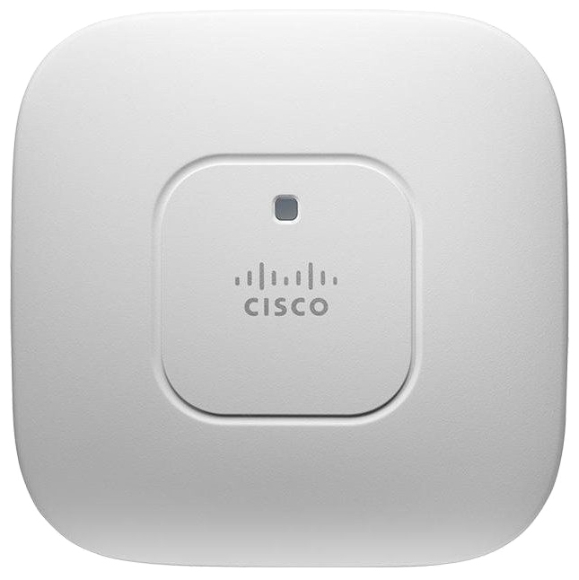
The 702I model access points have integrated antennas and do not have external connectors on the top of the unit; however, they do have the LED indicator on top of the unit, as shown in Figure 1.
Figure 1 Access Point LED Indicator (top)
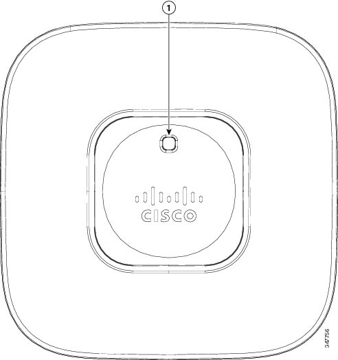
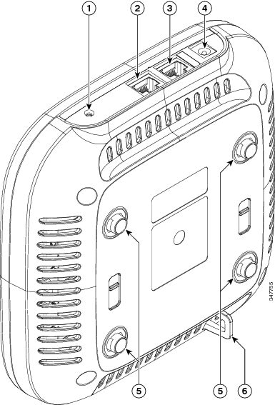
The ports and connections on the side of the access point are shown in Figure 2.
Figure 2 Access Point Ports and Connections (bottom)
|
1 |
Mode button |
4 |
AC power connector |
|
2 |
Ethernet port |
5 |
Mounting bracket pins |
|
3 |
Console port |
6 |
Security hasp |
Configuring the Access Point
This section describes how to connect the access point to a wireless LAN controller. Because the configuration process takes place on the controller, see the Cisco Wireless LAN Controller Configuration Guide for additional information. This guide is available on Cisco.com.
The Controller Discovery Process
The access point uses standard Control and Provisioning of Wireless Access Points Protocol (CAPWAP) to communicate between the controller and other wireless access points on the network. CAPWAP is a standard, interoperable protocol which enables an access controller to manage a collection of wireless termination points. The discovery process using CAPWAP is identical to the Lightweight Access Point Protocol (LWAPP) used with previous Cisco Aironet access points. LWAPP-enabled access points are compatible with CAPWAP, and conversion to a CAPWAP controller is seamless. Deployments can combine CAPWAP and LWAPP software on the controllers.
The functionality provided by the controller does not change except for customers who have Layer 2 deployments, which CAPWAP does not support.
In a CAPWAP environment, a wireless access point discovers a controller by using CAPWAP discovery mechanisms and then sends it a CAPWAP join request. The controller sends the access point a CAPWAP join response allowing the access point to join the controller. When the access point joins the controller, the controller manages its configuration, firmware, control transactions, and data transactions.
Note![]() For additional information about the discovery process and CAPWAP, see the Cisco Wireless LAN Controller Software Configuration Guide. This document is available on Cisco.com.
For additional information about the discovery process and CAPWAP, see the Cisco Wireless LAN Controller Software Configuration Guide. This document is available on Cisco.com.
Note![]() CAPWAP support is provided in controller software release 5.2 or later. However, your controller must be running release 7.5.x.x or later to support 700 series access points.
CAPWAP support is provided in controller software release 5.2 or later. However, your controller must be running release 7.5.x.x or later to support 700 series access points.
Note![]() You cannot edit or query any access point using the controller CLI if the name of the access point contains a space.
You cannot edit or query any access point using the controller CLI if the name of the access point contains a space.
Note![]() Make sure that the controller is set to the current time. If the controller is set to a time that has already occurred, the access point might not join the controller because its certificate may not be valid for that time.
Make sure that the controller is set to the current time. If the controller is set to a time that has already occurred, the access point might not join the controller because its certificate may not be valid for that time.
Access points must discovered a controller before they can become an active part of the network. The access point supports these controller discovery processes:
- Layer 3 CAPWAP discovery—The access point performs a local broadcast (255.255.255.255) discovery request to find any contollers on the same subnet/vlan. The request can be forwarded to other networks by the IP helper featuer that is present on switches and router.
- Locally stored controller IP address discovery—If the access point was previously joined to a controller, the IP addresses of the primary, secondary, and tertiary controllers are stored in the access point’s non-volatile memory. This process of storing controller IP addresses on an access point for later deployment is called priming the access point. For more information about priming, see the “Performing a Pre-Installation Configuration” section.
- DHCP server discovery—This feature uses DHCP option 43 to provide controller IP addresses to the access points. Cisco switches support a DHCP server option that is typically used for this capability. For more information about DHCP option 43, see the “Configuring DHCP Option 43 and DHCP Option 60” section.
- DNS discovery—The access point can discover controllers through your domain name server (DNS). For the access point to do so, you must configure your DNS to return controller IP addresses in response to CISCO-CAPWAP-CONTROLLER.localdomain, where localdomain is the access point domain name. Configuring the CISCO-CAPWAP-CONTROLLER provides backwards compatibility in an existing customer deployment. When an access point receives an IP address and DNS information from a DHCP server, it contacts the DNS to resolve CISCO-CAPWAP-CONTROLLER.localdomain. When the DNS sends a list of controller IP addresses, the access point sends discovery requests to the controllers.
Preparing the Access Point
Before you mount and deploy your access point, we recommend that you perform a site survey (or use the site planning tool) to determine the best location to install your access point.
You should have the following information about your wireless network available:
- Access point locations.
- Access point mounting options: below a suspended ceiling, on a flat horizontal surface, or on a desktop.
Note![]() You can mount the access point above a suspended ceiling but you must purchase additional mounting hardware: See “Mounting the Access Point” section for additional information.
You can mount the access point above a suspended ceiling but you must purchase additional mounting hardware: See “Mounting the Access Point” section for additional information.
- Access point power options: power supplied by the recommended external power supply (Cisco AIR-PWR-B), a DC power supply, PoE from a network device, or a PoE power injector/hub (the Cisco-recommended injector is the AIR-PWRINJ5=), usually located in a wiring closet.
Note![]() Access points mounted in a building’s environmental airspace must be powered using PoE to comply with safety regulations.
Access points mounted in a building’s environmental airspace must be powered using PoE to comply with safety regulations.
Cisco recommends that you make a site map showing access point locations so that you can record the device MAC addresses from each location and return them to the person who is planning or managing your wireless network.
Installation Summary
Installing the access point involves these operations:
- Performing a pre-installation configuration (optional)
- Mounting the access point
- Grounding the access point
- Deploying the access point on the wireless network
Performing a Pre-Installation Configuration
The following procedures ensure that your access point installation and initial operation go as expected. A pre-installation configuration is also known as priming the access point. This procedure is optional.
Note![]() Performing a pre-installation configuration is an optional procedure. If your network controller is properly configured, you can install your access point in its final location and connect it to the network from there. See the “Deploying the Access Point on the Wireless Network” section for details.
Performing a pre-installation configuration is an optional procedure. If your network controller is properly configured, you can install your access point in its final location and connect it to the network from there. See the “Deploying the Access Point on the Wireless Network” section for details.
Pre-Installation Configuration Setup
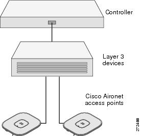
The pre-installation configuration setup is shown in Figure 3.
Figure 3 Pre-Installation Configuration Setup
To perform pre-installation configuration, perform the following steps:
Step 1![]() Make sure that the Cisco wireless LAN controller DS port is connected to the network. Use the CLI, web-browser interface, or Cisco Prime Infrastructure procedures as described in the appropriate Cisco wireless LAN controller guide.
Make sure that the Cisco wireless LAN controller DS port is connected to the network. Use the CLI, web-browser interface, or Cisco Prime Infrastructure procedures as described in the appropriate Cisco wireless LAN controller guide.
a.![]() Make sure that access points have Layer 3 connectivity to the Cisco wireless LAN controller Management.
Make sure that access points have Layer 3 connectivity to the Cisco wireless LAN controller Management.
b.![]() Configure the switch to which your access point is attach to. See the Cisco Unified Wireless Network WLAN Controller Configuration Guide for additional information.
Configure the switch to which your access point is attach to. See the Cisco Unified Wireless Network WLAN Controller Configuration Guide for additional information.
c.![]() Set the Cisco wireless LAN controller as the master so that new access points always join with it.
Set the Cisco wireless LAN controller as the master so that new access points always join with it.
d.![]() Make sure DHCP is enabled on the network. The access point must receive its IP address through DHCP.
Make sure DHCP is enabled on the network. The access point must receive its IP address through DHCP.
e.![]() CAPWAP UDP ports ( ports 5246 and 5247) must not be blocked in the network.
CAPWAP UDP ports ( ports 5246 and 5247) must not be blocked in the network.
f.![]() The access point must be able to find the IP address of the controller. This can be accomplished using DHCP, DNS, or IP subnet broadcast. This guide describes the DHCP method to convey the controller IP address. For other methods, refer to the product documentation. See also the “Using DHCP Option 43” section for more information.
The access point must be able to find the IP address of the controller. This can be accomplished using DHCP, DNS, or IP subnet broadcast. This guide describes the DHCP method to convey the controller IP address. For other methods, refer to the product documentation. See also the “Using DHCP Option 43” section for more information.
Step 2![]() Apply power to the access point:
Apply power to the access point:
a.![]() The access point is 802.3af (15.4 W) compliant and can be powered by any 802.3af compliant device.
The access point is 802.3af (15.4 W) compliant and can be powered by any 802.3af compliant device.
Note![]() The 700 series access point requires a Gigibit Ethernet link to prevent the Ethernet port from becoming a bottleneck for traffic because wireless traffic speeds exceed transmit speeds of a 10/100 Ethernet port.
The 700 series access point requires a Gigibit Ethernet link to prevent the Ethernet port from becoming a bottleneck for traffic because wireless traffic speeds exceed transmit speeds of a 10/100 Ethernet port.
b.![]() As the access point attempts to connect to the controller, the LEDs cycle through a green, red, and amber sequence, which can take up to 5 minutes.
As the access point attempts to connect to the controller, the LEDs cycle through a green, red, and amber sequence, which can take up to 5 minutes.
Note![]() If the access point remains in this mode for more than five minutes, the access point is unable to find the Master Cisco wireless LAN controller. Check the connection between the access point and the Cisco wireless LAN controller and be sure that they are on the same subnet.
If the access point remains in this mode for more than five minutes, the access point is unable to find the Master Cisco wireless LAN controller. Check the connection between the access point and the Cisco wireless LAN controller and be sure that they are on the same subnet.
c.![]() If the access point shuts down, check the power source.
If the access point shuts down, check the power source.
d.![]() After the access point finds the Cisco wireless LAN controller, it attempts to download the new operating system code if the access point code version differs from the Cisco wireless LAN controller code version. While this is happening, the Status LED blinks amber.
After the access point finds the Cisco wireless LAN controller, it attempts to download the new operating system code if the access point code version differs from the Cisco wireless LAN controller code version. While this is happening, the Status LED blinks amber.
e.![]() If the operating system download is successful, the access point reboots.
If the operating system download is successful, the access point reboots.
Step 3![]() Configure the access point if required. Use the controller CLI, controller GUI, or Cisco Prime Infrastructure to customize the access-point-specific 802.11n network settings.
Configure the access point if required. Use the controller CLI, controller GUI, or Cisco Prime Infrastructure to customize the access-point-specific 802.11n network settings.
Step 4![]() If the pre-installation configuration is successful, the Status LED is green indicating normal operation. Disconnect the access point and mount it at the location at which you intend to deploy it on the wireless network.
If the pre-installation configuration is successful, the Status LED is green indicating normal operation. Disconnect the access point and mount it at the location at which you intend to deploy it on the wireless network.
Step 5![]() If your access point does not indicate normal operation, turn it off and repeat the pre-installation configuration.
If your access point does not indicate normal operation, turn it off and repeat the pre-installation configuration.
Note![]() When you are installing a Layer 3 access point on a different subnet than the Cisco wireless LAN controller, be sure that a DHCP server is reachable from the subnet on which you will be installing the access point, and that the subnet has a route back to the Cisco wireless LAN controller. Also be sure that the route back to the Cisco wireless LAN controller has destination UDP ports 5246 and 5247 open for CAPWAP communications. Ensure that the route back to the primary, secondary, and tertiary wireless LAN controller allows IP packet fragments. Finally, be sure that if address translation is used, that the access point and the Cisco wireless LAN controller have a static 1-to-1 NAT to an outside address.
When you are installing a Layer 3 access point on a different subnet than the Cisco wireless LAN controller, be sure that a DHCP server is reachable from the subnet on which you will be installing the access point, and that the subnet has a route back to the Cisco wireless LAN controller. Also be sure that the route back to the Cisco wireless LAN controller has destination UDP ports 5246 and 5247 open for CAPWAP communications. Ensure that the route back to the primary, secondary, and tertiary wireless LAN controller allows IP packet fragments. Finally, be sure that if address translation is used, that the access point and the Cisco wireless LAN controller have a static 1-to-1 NAT to an outside address.
Deploying the Access Point on the Wireless Network
After you have mounted the access point, follow these steps to deploy it on the wireless network:
Step 1![]() Connect and power up the access point.
Connect and power up the access point.
Step 2![]() Observe the access point LED (for LED descriptions, see “Checking the Access Point LED” section).
Observe the access point LED (for LED descriptions, see “Checking the Access Point LED” section).
a.![]() When you power up the access point, it begins a power-up sequence that you can verify by observing the access point LED. If the power-up sequence is successful, the discovery and join process begins. During this process, the LED blinks sequentially green, red, and amber. When the access point has joined a controller, the LED chirps green if no clients are associated or stays green if one or more clients are associated.
When you power up the access point, it begins a power-up sequence that you can verify by observing the access point LED. If the power-up sequence is successful, the discovery and join process begins. During this process, the LED blinks sequentially green, red, and amber. When the access point has joined a controller, the LED chirps green if no clients are associated or stays green if one or more clients are associated.
b.![]() If the LED is not on, the access point is most likely not receiving power.
If the LED is not on, the access point is most likely not receiving power.
c.![]() If the LED blinks sequentially for more than 5 minutes, the access point is unable to find its primary, secondary, and tertiary Cisco wireless LAN controller. Check the connection between the access point and the Cisco wireless LAN controller, and be sure the access point and the Cisco wireless LAN controller are either on the same subnet or that the access point has a route back to its primary, secondary, and tertiary Cisco wireless LAN controller. Also, if the access point is not on the same subnet as the Cisco wireless LAN controller, be sure that there is a properly configured DHCP server on the same subnet as the access point. See the “Configuring DHCP Option 43 and DHCP Option 60” section for additional information.
If the LED blinks sequentially for more than 5 minutes, the access point is unable to find its primary, secondary, and tertiary Cisco wireless LAN controller. Check the connection between the access point and the Cisco wireless LAN controller, and be sure the access point and the Cisco wireless LAN controller are either on the same subnet or that the access point has a route back to its primary, secondary, and tertiary Cisco wireless LAN controller. Also, if the access point is not on the same subnet as the Cisco wireless LAN controller, be sure that there is a properly configured DHCP server on the same subnet as the access point. See the “Configuring DHCP Option 43 and DHCP Option 60” section for additional information.
Step 3![]() Reconfigure the Cisco wireless LAN controller so that it is not the Master.
Reconfigure the Cisco wireless LAN controller so that it is not the Master.
Note![]() A Master Cisco wireless LAN controller should be used only for configuring access points and not in a working network.
A Master Cisco wireless LAN controller should be used only for configuring access points and not in a working network.
Troubleshooting
If you experience difficulty getting your access point installed and running, look for a solution to your problem in this guide or in additional access point documentation. These, and other documents, are available on Cisco.com.
Guidelines for Using Cisco Aironet Lightweight Access Points
Keep these guidelines in mind when you use 700 series lightweight access points:
- The access point can only communicate with Cisco wireless LAN controllers, such as 2500 series, 5500 series, 7500 series, 8500 series, virtual Wireless LAN Controllers, and WiSM2 controllers.
- The access point does not support Wireless Domain Services (WDS) and cannot communicate with WDS devices. However, the controller provides functionality equivalent to WDS when the access point joins it.
- CAPWAP does not support Layer 2. The access point must get an IP address and discover the controller using Layer 3, DHCP, DNS, or IP subnet broadcast.
- The access point console port is enabled for monitoring and debug purposes. All configuration commands are disabled when the access point is connected to a controller.
Checking the Access Point LED
The location of the access point status LED is shown in Figure 1.
Note![]() Regarding LED status colors, it is expected that there will be small variations in color intensity and hue from unit to unit. This is within the normal range of the LED manufacturer’s specifications and is not a defect.
Regarding LED status colors, it is expected that there will be small variations in color intensity and hue from unit to unit. This is within the normal range of the LED manufacturer’s specifications and is not a defect.
The access point status LED indicates various conditions and are described in Table 1.
|
Message |
Status |
Message Meaning |
|---|---|---|
|
Boot loader status sequence |
Blinking green |
DRAM memory test in progress |
|
DRAM memory test OK |
||
|
Board initialization in progress |
||
|
Initializing FLASH file system |
||
|
FLASH memory test OK |
||
|
Initializing Ethernet |
||
|
Ethernet OK |
||
|
Starting Cisco IOS |
||
|
Initialization successful |
||
|
Association status |
Chirping Green |
Normal operating condition, but no wireless client associated |
|
Green |
Normal operating condition, at least one wireless client association |
|
|
Operating status |
Blinking amber |
Software upgrade in progress |
|
Cycling through green, red, and amber |
Discovery/join process in progress |
|
|
Rapidly cycling through red, green, and amber |
Access point location command invoked |
|
|
Blinking red |
Ethernet link not operational |
|
|
Boot loader warnings |
Blinking amber |
Configuration recovery in progress (MODE button pushed for 2 to 3 seconds) |
|
Red |
Ethernet failure or image recovery (MODE button pushed for 20 to 30 seconds) |
|
|
Blinking green |
Image recovery in progress (MODE button released) |
|
|
Boot loader errors |
Red |
DRAM memory test failure |
|
Blinking red and amber |
FLASH file system failure |
|
|
Blinking red and off |
Environment variable failure |
|
|
Bad MAC address |
||
|
Ethernet failure during image recovery |
||
|
Boot environment failure |
||
|
No Cisco image file |
||
|
Boot failure |
||
|
Cisco IOS errors |
Red |
Software failure; try disconnecting and reconnecting unit power |
|
Cycling through red, green, amber, and off |
General warning; insufficient inline power |
Troubleshooting the Access Point Join Process
Access points can fail to join a controller for many reasons: a RADIUS authorization is pending; self-signed certificates are not enabled on the controller; the access point’s and controller’s regulatory domains don’t match, and so on.
Controller software enables you to configure the access points to send all CAPWAP-related errors to a syslog server. You do not need to enable any debug commands on the controller because all of the CAPWAP error messages can be viewed from the syslog server itself.
The state of the access point is not maintained on the controller until it receives a CAPWAP join request from the access point. Therefore, it can be difficult to determine why the CAPWAP discovery request from a certain access point was rejected. In order to troubleshoot such joining problems without enabling CAPWAP debug commands on the controller, the controller collects information for all access points that send a discovery message to it and maintains information for any access points that have successfully joined it.
The controller collects all join-related information for each access point that sends a CAPWAP discovery request to the controller. Collection begins with the first discovery message received from the access point and ends with the last configuration payload sent from the controller to the access point.
An access point sends all syslog messages to IP address 255.255.255.255 by default when any of the following conditions are met:
- An access point running software release 5.2 or later has been newly deployed.
- An existing access point running software release 5.2 or later has been reset after clearing the configuration.
If any of these conditions are met and the access point has not yet joined a controller, you can also configure a DHCP server to return a syslog server IP address to the access point using option 7 on the server. The access point then starts sending all syslog messages to this IP address.
When the access point joins a controller for the first time, the controller sends the global syslog server IP address (the default is 255.255.255.255) to the access point. After that, the access point sends all syslog messages to this IP address until it is overridden by one of the following scenarios:
- The access point is still connected to the same controller, and the global syslog server IP address configuration on the controller has been changed using the config ap syslog host global syslog_server_IP_address command. In this case, the controller sends the new global syslog server IP address to the access point.
- The access point is still connected to the same controller, and a specific syslog server IP address has been configured for the access point on the controller using the config ap syslog host specific Cisco_AP syslog_server_IP_address command. In this case, the controller sends the new specific syslog server IP address to the access point.
- The access point is disconnected from the controller and joins another controller. In this case, the new controller sends its global syslog server IP address to the access point.
- Whenever a new syslog server IP address overrides the existing syslog server IP address, the old address is erased from persistent storage, and the new address is stored in its place. The access point also starts sending all syslog messages to the new IP address provided the access point can reach the syslog server IP address.
You can configure the syslog server for access points and view the access point join information only from the controller CLI.
A detailed explanation of the join process is on Cisco.com at the following URL:
http://www.Cisco.com/en/US/products/ps6366/products_tech_note09186a00808f8599.shtml
Declarations of Conformity and Regulatory Information
This section provides declarations of conformity and regulatory information for Cisco Aironet 700 Series Access Points. You can find additional information at this URL:
www.cisco.com/go/aironet/compliance
Manufacturers Federal Communication Commission Declaration of Conformity Statement

|
Models |
Certification Numbers |
|---|---|
|
AIR-CAP702I-A-K9 AIR-SAP702I-B-K9 |
LDK102085 |
Manufacturer:
Cisco Systems, Inc.
170 West Tasman Drive
San Jose, CA 95134-1706
USA
This device complies with Part 15 rules. Operation is subject to the following two conditions:
1.![]() This device may not cause harmful interference, and
This device may not cause harmful interference, and
2.![]() This device must accept any interference received, including interference that may cause undesired operation.
This device must accept any interference received, including interference that may cause undesired operation.
This device operates in the 5150-5250MHz and 5470-5725MHz bands and is therefore restricted to indoor operation only per FCC guidance.
This equipment has been tested and found to comply with the limits of a Class B digital device, pursuant to Part 15 of the FCC Rules. These limits are designed to provide reasonable protection against harmful interference when the equipment is operated in a residential environment. This equipment generates, uses, and radiates radio frequency energy, and if not installed and used in accordance with the instructions, may cause harmful interference. However, there is no guarantee that interference will not occur. If this equipment does cause interference to radio or television reception, which can be determined by turning the equipment off and on, the user is encouraged to correct the interference by one of the following measures:
- Reorient or relocate the receiving antenna.
- Increase separation between the equipment and receiver.
- Connect the equipment to an outlet on a circuit different from which the receiver is connected.
- Consult the dealer or an experienced radio/TV technician.
Caution
![]() The Part 15 radio device operates on a non-interference basis with other devices operating at this frequency when using the integrated antennas. Any changes or modification to the product not expressly approved by Cisco could void the user’s authority to operate this device.
The Part 15 radio device operates on a non-interference basis with other devices operating at this frequency when using the integrated antennas. Any changes or modification to the product not expressly approved by Cisco could void the user’s authority to operate this device.
Caution
![]() Within the 5.15 to 5.25 GHz and 5.47-5.725 GHz bands, this device is restricted to indoor operations to reduce any potential for harmful interference to co-channel Mobile Satellite System (MSS) operations.
Within the 5.15 to 5.25 GHz and 5.47-5.725 GHz bands, this device is restricted to indoor operations to reduce any potential for harmful interference to co-channel Mobile Satellite System (MSS) operations.
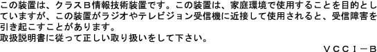
VCCI Statement for Japan
|
Warning |
This is a Class B product based on the standard of the Voluntary Control Council for Interference from Information Technology Equipment (VCCI). If this is used near a radio or television receiver in a domestic environment, it may cause radio interference. Install and use the equipment according to the instruction manual. |
|
|
|

Guidelines for Operating Cisco Aironet Access Points in Japan
This section provides guidelines for avoiding interference when operating Cisco Aironet access points in Japan. These guidelines are provided in both Japanese and English.
Japanese Translation
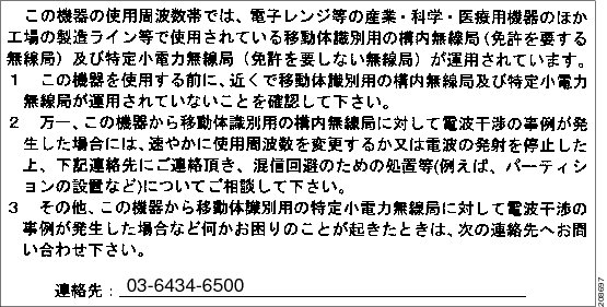
English Translation
This equipment operates in the same frequency bandwidth as industrial, scientific, and medical devices such as microwave ovens and mobile object identification (RF-ID) systems (licensed premises radio stations and unlicensed specified low-power radio stations) used in factory production lines.
1.![]() Before using this equipment, make sure that no premises radio stations or specified low-power radio stations of RF-ID are used in the vicinity.
Before using this equipment, make sure that no premises radio stations or specified low-power radio stations of RF-ID are used in the vicinity.
2.![]() If this equipment causes RF interference to a premises radio station of RF-ID, promptly change the frequency or stop using the device; contact the number below and ask for recommendations on avoiding radio interference, such as setting partitions.
If this equipment causes RF interference to a premises radio station of RF-ID, promptly change the frequency or stop using the device; contact the number below and ask for recommendations on avoiding radio interference, such as setting partitions.
3.![]() If this equipment causes RF interference to a specified low-power radio station of RF-ID, contact the number below.
If this equipment causes RF interference to a specified low-power radio station of RF-ID, contact the number below.
Contact Number: 03-6434-6500
Statement 371—Power Cable and AC Adapter
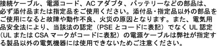
English Translation
When installing the product, please use the provided or designated connection cables/power cables/AC adaptors. Using any other cables/adaptors could cause a malfunction or a fire. Electrical Appliance and Material Safety Law prohibits the use of UL-certified cables (that have the “UL” shown on the code) for any other electrical devices than products designated by CISCO. The use of cables that are certified by Electrical Appliance and Material Safety Law (that have “PSE” shown on the code) is not limited to CISCO-designated products.
Industry Canada
Canadian Compliance Statement
|
Models |
Certification Numbers |
|---|---|
|
AIR-CAP702I-A-K9 |
2461B-102085 |
This Class B Digital apparatus meets all the requirements of the Canadian Interference-Causing Equipment Regulations.
This device complies with Class B Limits of Industry Canada. Operation is subject to the following two conditions:
1.![]() This device may not cause harmful interference, and
This device may not cause harmful interference, and
2.![]() This device must accept any interference received, including interference that may cause undesired operation.
This device must accept any interference received, including interference that may cause undesired operation.
Cisco Aironet Access Points are certified to the requirements of RSS-210. The use of this device in a system operating either partially or completely outdoors may require the user to obtain a license for the system according to the Canadian regulations. For further information, contact your local Industry Canada office.
This device has been designed to operate with antennas having a maximum gain of 5 dBi. Antennas having a gain greater than 5 dBi are strictly prohibited for use with this device. The required antenna impedance is 50 ohms.
To reduce potential radio interference to other users, the antenna type and its gain should be so chosen that the equivalent isotropically radiated power (EIRP) is not more than that permitted for successful communication.
French Translation
Cet appareil numerique de la classe B respecte les exigences du Reglement sur le material broilleur du Canada.
Cet appareil respecte les limites prescrites pour les appareils de classe B par Industrie Canada. Son utilisation est soumise aux deux conditions suivantes :
(1) Cet appareil ne doit pas causer d’interf_rences nuisibles, et
(2) Cet appareil doit accepter toutes les interf_rences, y compris celles susceptibles de perturber le fonctionnement de l’appareil.
Les points d’acc_s Aironet de Cisco sont certifi_s conform_ment aux exigences du CNR-210. L’utilisation de cet appareil dans un syst_me fonctionnant partiellement ou enti_rement ˆ l’ext_rieur peut n_cessiter l’obtention d’une licence pour le syst_me, conform_ment ˆ la r_glementation canadienne. Pour plus de renseignements, communiquez avec le bureau local d’Industrie Canada.
Cet appareil a _t_ con_u pour fonctionner avec une antenne d’un gain maximum de 6 dBi. Il est strictement interdit d’utiliser des antennes ayant un gain sup_rieur ˆ 6 dBi avec cet appareil. L’antenne doit avoir une imp_dance de 50 ohms.
Afin de r_duire le risque d’interf_rence aux autres utilisateurs, le type d’antenne et son gain doivent _tre choisis de fa_on ˆ ce que la puissance isotrope rayonn_e _quivalente (p.i.r.e.) ne soit pas sup_rieure au niveau requis pour obtenir une communication satisfaisante.
European Community, Switzerland, Norway, Iceland, and Liechtenstein
Models:
AIR-CAP702I-E-K9
AIR-SAP702I-E-K9
Declaration of Conformity with regard to the R&TTE Directive 1999/5/EC & Medical Directive 93/42/EEC
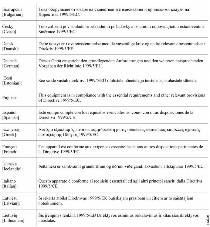
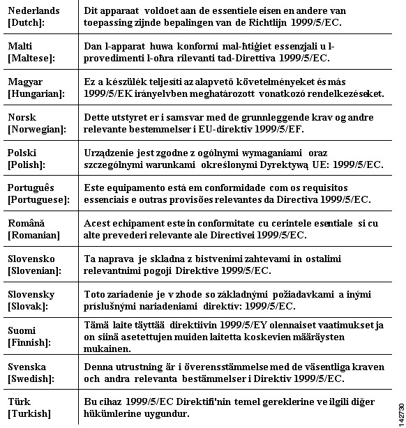
The following standards were applied:
EMC—EN 301.489-1 v1.8.1; EN 301.489-17 v2.1.1
Health & Safety—EN60950-1: 2005; EN 50385: 2002
Radio—EN 300 328 v 1.7.1; EN 301.893 v 1.5.1
The conformity assessment procedure referred to in Article 10.4 and Annex III of Directive 1999/5/EC has been followed.
This device also conforms to the EMC requirements of the Medical Devices Directive 93/42/EEC.
Note![]() This equipment is intended to be used in all EU and EFTA countries. Outdoor use may be restricted to certain frequencies and/or may require a license for operation. For more details, contact Cisco Corporate Compliance.
This equipment is intended to be used in all EU and EFTA countries. Outdoor use may be restricted to certain frequencies and/or may require a license for operation. For more details, contact Cisco Corporate Compliance.
The product carries the CE Mark:

Declaration of Conformity for RF Exposure
This section contains information on compliance with guidelines related to RF exposure.
Generic Discussion on RF Exposure
The Cisco products are designed to comply with the following national and international standards on Human Exposure to Radio Frequencies:
- US 47 Code of Federal Regulations Part 2 Subpart J
- American National Standards Institute (ANSI) / Institute of Electrical and Electronic Engineers / IEEE C 95.1 (99)
- International Commission on Non Ionizing Radiation Protection (ICNIRP) 98
- Ministry of Health (Canada) Safety Code 6. Limits on Human Exposure to Radio Frequency Fields in the range from 3kHz to 300 GHz
- Australia Radiation Protection Standard
To ensure compliance with various national and international Electromagnetic Field (EMF) standards, the system should only be operated with Cisco approved antennas and accessories.
This Device Meets International Guidelines for Exposure to Radio Waves
The 700 series device includes a radio transmitter and receiver. It is designed not to exceed the limits for exposure to radio waves (radio frequency electromagnetic fields) recommended by international guidelines. The guidelines were developed by an independent scientific organization (ICNIRP) and include a substantial safety margin designed to ensure the safety of all persons, regardless of age and health.
As such the systems are designed to be operated as to avoid contact with the antennas by the end user. It is recommended to set the system in a location where the antennas can remain at least a minimum distance as specified from the user in accordance to the regulatory guidelines which are designed to reduce the overall exposure of the user or operator.
|
Separation Distance |
||
|---|---|---|
|
MPE |
Distance |
Limit |
|
0.63 mW/cm2 |
20 cm (7.87 inches) |
1.00 mW/cm2 |
The World Health Organization has stated that present scientific information does not indicate the need for any special precautions for the use of wireless devices. They recommend that if you are interested in further reducing your exposure then you can easily do so by reorienting antennas away from the user or placing he antennas at a greater separation distance then recommended.
This Device Meets FCC Guidelines for Exposure to Radio Waves
The 700 series device includes a radio transmitter and receiver. It is designed not to exceed the limits for exposure to radio waves (radio frequency electromagnetic fields) as referenced in FCC Part 1.1310. The guidelines are based on IEEE ANSI C 95.1 (92) and include a substantial safety margin designed to ensure the safety of all persons, regardless of age and health.
As such the systems are designed to be operated as to avoid contact with the antennas by the end user. It is recommended to set the system in a location where the antennas can remain at least a minimum distance as specified from the user in accordance to the regulatory guidelines which are designed to reduce the overall exposure of the user or operator.
The device has been tested and found compliant with the applicable regulations as part of the radio certification process.
|
Separation Distance |
||
|---|---|---|
|
MPE |
Distance |
Limit |
|
0.63 mW/cm2 |
20 cm (7.87 inches) |
1.00 mW/cm2 |
The US Food and Drug Administration has stated that present scientific information does not indicate the need for any special precautions for the use of wireless devices. The FCC recommends that if you are interested in further reducing your exposure then you can easily do so by reorienting antennas away from the user or placing the antennas at a greater separation distance then recommended or lowering the transmitter power output.
This Device Meets the Industry Canada Guidelines for Exposure to Radio Waves
The 700 series device includes a radio transmitter and receiver. It is designed not to exceed the limits for exposure to radio waves (radio frequency electromagnetic fields) as referenced in Health Canada Safety Code 6. The guidelines include a substantial safety margin designed into the limit to ensure the safety of all persons, regardless of age and health.
As such the systems are designed to be operated as to avoid contact with the antennas by the end user. It is recommended to set the system in a location where the antennas can remain at least a minimum distance as specified from the user in accordance to the regulatory guidelines which are designed to reduce the overall exposure of the user or operator.
|
Separation Distance |
||
|---|---|---|
|
MPE |
Distance |
Limit |
|
0.63 mW/cm2 |
20 cm (7.87 inches) |
1.00 mW/cm2 |
Health Canada states that present scientific information does not indicate the need for any special precautions for the use of wireless devices. They recommend that if you are interested in further reducing your exposure you can easily do so by reorienting antennas away from the user, placing the antennas at a greater separation distance than recommended, or lowering the transmitter power output.
Cet appareil est conforme aux directives internationales en matière d’exposition aux fréquences radioélectriques
Cet appareil de la gamme 1700 comprend un émetteur-récepteur radio. Il a été conçu de manière à respecter les limites en matière d’exposition aux fréquences radioélectriques (champs électromagnétiques de fréquence radio), recommandées dans le code de sécurité 6 de Santé Canada. Ces directives intègrent une marge de sécurité importante destinée à assurer la sécurité de tous, indépendamment de l’âge et de la santé.
Par conséquent, les systèmes sont conçus pour être exploités en évitant que l’utilisateur n’entre en contact avec les antennes. Il est recommandé de poser le système là où les antennes sont à une distance minimale telle que précisée par l’utilisateur conformément aux directives réglementaires qui sont conçues pour réduire l’exposition générale de l’utilisateur ou de l’opérateur.
|
Distance d’éloignement |
||
|---|---|---|
|
MPE |
Distance |
Limite |
|
0.63 mW/cm2 |
20 cm (7.87 po) |
1.00 mW/cm2 |
Santé Canada affirme que la littérature scientifique actuelle n’indique pas qu’il faille prendre des précautions particulières lors de l’utilisation d’un appareil sans fil. Si vous voulez réduire votre exposition encore davantage, selon l’agence, vous pouvez facilement le faire en réorientant les antennes afin qu’elles soient dirigées à l’écart de l’utilisateur, en les plaçant à une distance d’éloignement supérieure à celle recommandée ou en réduisant la puissance de sortie de l’émetteur.
Additional Information on RF Exposure
You can find additional information on the subject at the following links:
- Cisco Systems Spread Spectrum Radios and RF Safety white paper at this URL:
http://www.cisco.com/warp/public/cc/pd/witc/ao340ap/prodlit/rfhr_wi.htm - FCC Bulletin 56: Questions and Answers about Biological Effects and Potential Hazards of Radio Frequency Electromagnetic Fields
- FCC Bulletin 65: Evaluating Compliance with the FCC guidelines for Human Exposure to Radio Frequency Electromagnetic Fields
- FCC Bulletin 65C (01-01): Evaluating Compliance with the FCC guidelines for Human Exposure to Radio Frequency Electromagnetic Fields: Additional Information for Evaluating Compliance for Mobile and Portable Devices with FCC limits for Human Exposure to Radio Frequency Emission
You can obtain additional information from the following organizations:
- World Health Organization Internal Commission on Non-Ionizing Radiation Protection at this URL: www.who.int/emf
- United Kingdom, National Radiological Protection Board at this URL: www.nrpb.org.uk
- Cellular Telecommunications Association at this URL: www.wow-com.com
- The Mobile Manufacturers Forum at this URL: www.mmfai.org
Administrative Rules for Cisco Aironet Access Points in Taiwan
This section provides administrative rules for operating Cisco Aironet access points in Taiwan. The rules for all access points are provided in both Chinese and English.
Chinese Translation
English Translation
Administrative Rules for Low-power Radio-Frequency Devices
Article 12
For those low-power radio-frequency devices that have already received a type-approval, companies, business units or users should not change its frequencies, increase its power or change its original features and functions.
Article 14
The operation of the low-power radio-frequency devices is subject to the conditions that no harmful interference is caused to aviation safety and authorized radio station; and if interference is caused, the user must stop operating the device immediately and can’t re-operate it until the harmful interference is clear.
The authorized radio station means a radio-communication service operating in accordance with the Communication Act.
The operation of the low-power radio-frequency devices is subject to the interference caused by the operation of an authorized radio station, by another intentional or unintentional radiator, by industrial, scientific and medical (ISM) equipment, or by an incidental radiator.
Chinese Translation
English Translation
Low-power Radio-frequency Devices Technical Specifications
|
4.7 |
Unlicensed National Information Infrastructure |
|
4.7.5 |
Within the 5.25-5.35 GHz band, U-NII devices will be restricted to indoor operations to reduce any potential for harmful interference to co-channel MSS operations. |
|
4.7.6 |
The U-NII devices shall accept any interference from legal communications and shall not interfere the legal communications. If interference is caused, the user must stop operating the device immediately and can’t re-operate it until the harmful interference is clear. |
|
4.7.7 |
Manufacturers of U-NII devices are responsible for ensuring frequency stability such that an emission is maintained within the band of operation under all conditions of normal operation as specified in the user manual. |
Operation of Cisco Aironet Access Points in Brazil
This section contains special information for operation of Cisco Aironet access points in Brazil.
Access Point Models
AIR-CAP702I-T-K9
AIR-SAP702I-T-K9
Figure 4 Brazil Regulatory Information

Portuguese Translation
Este equipamento opera em caráter secundário, isto é, não tem direito a proteção contra interferência prejudicial, mesmo de estações do mesmo tipo, e não pode causar interferência a sistemas operando em caráter primário.
English Translation
This equipment operates on a secondary basis and consequently must accept harmful interference, including interference from stations of the same kind. This equipment may not cause harmful interference to systems operating on a primary basis.
Declaration of Conformity Statements
All the Declaration of Conformity statements related to this product can be found at the following location: http://www.ciscofax.com
Configuring DHCP Option 43 and DHCP Option 60
This section contains a DHCP Option 43 configuration example on a Windows 2003 Enterprise DHCP server for use with Cisco Aironet lightweight access points. For other DHCP server implementations, consult product documentation for configuring DHCP Option 43. In Option 43, you should use the IP address of the controller management interface.
Note![]() DHCP Option 43 is limited to one access point type per DHCP pool. You must configure a separate DHCP pool for each access point type.
DHCP Option 43 is limited to one access point type per DHCP pool. You must configure a separate DHCP pool for each access point type.
The 700 series access point uses the type-length-value (TLV) format for DHCP Option 43. DHCP servers must be programmed to return the option based on the access point’s DHCP Vendor Class Identifier (VCI) string (DHCP Option 60). The VCI string for the 700 series access point is:
Cisco AP c700
Note![]() If your access point was ordered with the Service Provider Option (AIR-OPT60-DHCP) selected in the ordering tool, the VCI string for the access point contains ServiceProvider. For example, a 700 with this option will return this VCI string:
If your access point was ordered with the Service Provider Option (AIR-OPT60-DHCP) selected in the ordering tool, the VCI string for the access point contains ServiceProvider. For example, a 700 with this option will return this VCI string:
Cisco AP c700-ServiceProvider
The format of the TLV block is listed below:
- Type: 0xf1 (decimal 241)
- Length: Number of controller IP addresses * 4
- Value: List of WLC management interfaces
To configure DHCP Option 43 in the embedded Cisco IOS DHCP server, follow these steps:
Step 1![]() Enter configuration mode at the Cisco IOS CLI.
Enter configuration mode at the Cisco IOS CLI.
Step 2![]() Create the DHCP pool, including the necessary parameters such as default router and name server. A DHCP scope example is as follows:
Create the DHCP pool, including the necessary parameters such as default router and name server. A DHCP scope example is as follows:
ip dhcp pool <pool name>
network <IP Network> <Netmask>
default-router <Default router>
dns-server <DNS Server>
Where:
<pool name> is the name of the DHCP pool, such as AP702
<IP Network> is the network IP address where the controller resides, such as 10.0.15.1
<Netmask> is the subnet mask, such as 255.255.255.0
<Default router> is the IP address of the default router, such as 10.0.0.1
<DNS Server> is the IP address of the DNS server, such as 10.0.10.2
Step 3![]() Add the option 60 line using the following syntax:
Add the option 60 line using the following syntax:
option 60 ascii “VCI string”
For the VCI string, “Cisco AP c702”. The quotation marks must be included.
Step 4![]() Add the option 43 line using the following syntax:
Add the option 43 line using the following syntax:
option 43 hex <hex string>
The hex string is assembled by concatenating the TLV values shown below:
Type + Length + Value
Type is always f1(hex). Length is the number of controller management IP addresses times 4 in hex. Value is the IP address of the controller listed sequentially in hex.
For example, suppose that there are two controllers with management interface IP addresses, 10.126.126.2 and 10.127.127.2. The type is f1(hex). The length is 2 * 4 = 8 = 08 (hex). The IP addresses translate to 0a7e7e02 and 0a7f7f02. Assembling the string then yields f1080a7e7e020a7f7f02. The resulting Cisco IOS command added to the DHCP scope is option 43 hex f1080a7e7e020a7f7f02.
Obtaining Documentation and Submitting a Service Request
For information on obtaining documentation, submitting a service request, and gathering additional information, see What’s New in Cisco Product Documentation at:
http://www.cisco.com/en/US/docs/general/whatsnew/whatsnew.html
Subscribe to What’s New in Cisco Product Documentation, which lists all new and revised Cisco technical documentation, as an RSS feed and deliver content directly to your desktop using a reader application. The RSS feeds are a free service.
Cisco and the Cisco logo are trademarks or registered trademarks of Cisco and/or its affiliates in the U.S. and other countries. To view a list of Cisco trademarks, go to this URL: www.cisco.com/go/trademarks. Third-party trademarks mentioned are the property of their respective owners. The use of the word partner does not imply a partnership relationship between Cisco and any other company. (1721R)
Any Internet Protocol (IP) addresses used in this document are not intended to be actual addresses. Any examples, command display output, and figures included in the document are shown for illustrative purposes only. Any use of actual IP addresses in illustrative content is unintentional and coincidental.
© 2019- 2014 Cisco Systems, Inc. All rights reserved.
Рейтинг точки доступа:
(3.67 — 3 голосов)
Дать ссылку друзьям:
Рейтинг: Пока без рейтинга
Наличие инструкции подключения и альтернативной прошивки: В наличии
Настройка подключения
На данной странице вы узнаете как подключить Wi-Fi маршрутизатор к компьютеру, а также сможете найти инструкцию по настройке на русском языке.
Сотрудники нашего информационного портала ежедневно обновляют официальные прошивки для той или иной модели устройства.
Настройка Вай-Фай
Пошаговая настройка роутера Cisco AIR-SAP702I для Ростелеком, Билайн и других интернет провайдеров займет у Вас несколько минут и после этого вы сможете наслаждаться всеми достоинствами Wi-Fi точки доступа Циско.
Настройка IPTV
Если вы хотите получить последнюю версию официальной прошивки и инструкцию по подключению VPN или PPPOE и настройка IPTV телевидения для этого устройства на русском языке на ваш Email, то вам следует оставить полный, развернутый отзыв о той или иной модели Вай-Фай устройства.
Скачать прошивку для маршрутизатораЧтобы скачать прошивку для Cisco AIR-SAP702I вам достаточно внимательно ознакомиться со страницей, на которой вы сейчас находитесь. Не забывайте оставлять свои отзывы (форма для добавления отзывов находится в нижней части страницы). Если вас не затруднит, то вы можете поделиться ссылкой на прошивку со своими друзьями. Также, если вы не нашли ответ на свой вопрос, то вы можете задать его воспользовавшись формой в нижней части сайта. У нас вы найдете последние версии драйверов для беспроводных устройств. Чтобы скачать новый драйвер, вам необходимо перейти по ссылке «Скачать прошивку», которая расположена чуть ниже.
Скачать прошивку Настройки роутера Видео как настроить Cisco AIR-SAP702I |
|
-
Cisco AIR-CAP702I-I-K9 — page 1
G ETTING S TARTED G UIDE Cisco Aironet 700 Series Access Points First Published: June 2013 Last Updated: September 2014 1 About this Guide 2 Introduction to the Access Point 3 Safety Instructi ons 4 Unpacking 5 Configuratio ns 6 Access Point Ports and Connectors 7 Configuring the Access Point 8 Mounting the Access Point 9 Deploying the Access Point …
-
Cisco AIR-CAP702I-I-K9 — page 2
2 1 About this Guide This Guide provides in structions on how to install and conf igure your Cisco Aironet 700 Seri es Access Point. The 700 Series Access Point is referred to as the 700 series or the access point in this document. 2 Introduction to the Access Point The 700 series supports high-performing two spatial stream rates over a deployab le …
-
Cisco AIR-CAP702I-I-K9 — page 3
3 War n in g IMPORT ANT SAFETY INSTRUCTIONS This warning symbol means d anger . Y ou are in a situation that could cause bod ily injury . Before you work on any equipment, be aware of the hazards invo lved with electrical circuitry and be familiar with standard practices for preventing accidents. Use the statement number provided at the end of ea c …
-
Cisco AIR-CAP702I-I-K9 — page 4
4 4 Unpacking T o unpack the access point , follow these steps: Step 1 Unpa ck and remove the access point and the accessory kit from the shipping box . Step 2 Re turn any packing material to the shippi ng con tainer and save it for future use. Step 3 V erify that you have received the items lis ted below . If any item is missing or da maged, conta …
-
Cisco AIR-CAP702I-I-K9 — page 5
5 Figur e 1 Access P oint LED Indicator (t op) The ports and connections on the side of the access point are shown in Figure 2 . 1 LED indicator 347756 1 …
-
Cisco AIR-CAP702I-I-K9 — page 6
6 Figur e 2 Access P oint P orts and Connection s (bot tom) 7 Configuring the Access Point This section describes how to connect the access point to a wir eless LAN controller . Because th e configura tion process takes place on the co ntroller , see the Cisco Wireless LAN Controller Configuration Guide for additional information. This guide is ava …
-
Cisco AIR-CAP702I-I-K9 — page 7
7 The Controller Discovery Process The access point uses standard Control and Provisioning of Wireless Access Points Protocol (CAPW AP ) to communicate between the controller and other wireless access points on the network. CAPW AP is a standard, interoperable pro tocol which enables an access controller to ma nage a collection of wirele ss termina …
-
Cisco AIR-CAP702I-I-K9 — page 8
8 Preparing the Access Point Before you mount and deploy your access poin t, we recommend that you perform a site su rvey (or use the site planning tool) to determine the best location to install your access point. Y ou should have the following in formation about your wireless network available: • Access point locations. • Access point mountin …
-
Cisco AIR-CAP702I-I-K9 — page 9
9 Figure 3 Pr e-Installat ion Configuration Setup T o perform pre-installati on configuration, perform the following steps: Step 1 Mak e sure that the Cisco wireless LAN controller DS port is connected to the network. Use the CLI, web-browser interface, or Cisco Prime Infras tructure procedures as de scri bed in the appropriate Cisc o wireless LA N …
-
Cisco AIR-CAP702I-I-K9 — page 10
10 e. If the operating system download is successful, the access point reboots. Step 3 Config ure the access point if required. Use the controller CLI, contro ller GUI, or Cisco P rime Infrastructure to customize the access-point-spe cific 802.11n network settings. Step 4 If the pre-installatio n configuration is successful, the Status LED is green …
-
Cisco AIR-CAP702I-I-K9 — page 11
11 10 Troubleshooting If you experience difficulty getting your access point installe d a nd running, look for a solution to your problem in this guide or in additional access point documentation. These, an d other documents, are available on Cisco.com. Guidelines for Using Cisco Ai ronet Lightweigh t Access Points Keep these guidelines in mind whe …
-
Cisco AIR-CAP702I-I-K9 — page 12
12 Troubleshooting the Ac cess Point Join Process Access points can fail to join a controller for many reasons: a RADIUS authorization is pending; self-signe d certificates are n ot enabled on the controller; the access point’ s a nd controller’ s regu latory domains don’t match, and so on. Controller software enables you to configure th e ac …
-
Cisco AIR-CAP702I-I-K9 — page 13
13 An access point sends all syslo g messages to IP address 255.255.255.255 b y default when any of the following conditions are met: • An access point running software release 5.2 or later has been newly deploy ed. • An existing access point running softw are release 5.2 or later has been re set after clearing the configuration. If any of thes …
-
Cisco AIR-CAP702I-I-K9 — page 14
14 Manufacturer: Cisco Systems, Inc. 170 W est T asman Drive San Jose, CA 95134-1706 USA This device complies with Part 15 rules. Operation is subject to the followin g two conditions: 1. This device ma y not cause harmful interference, a nd 2. This device must accept any interference received, incl uding interference that may ca use undesired oper …
-
Cisco AIR-CAP702I-I-K9 — page 15
15 Guidelines for Operating Cisco Aironet Access Points in Japan This section provides guidelines for avoiding interference when operating Cisco Aironet a ccess po ints in Ja pan. These guideline s are provided in both Japanese and English. Japanese Translation English Translation This equipment operates in the same freque ncy bandwidth as industri …
-
Cisco AIR-CAP702I-I-K9 — page 16
16 English Translation When installing the product, please use the provid ed or designated connection cables/power cables/AC adaptors. Using any other cables/adaptors could cause a malfunction or a fire. Elect rical Appliance an d Material Safety Law proh ibits the use of UL-certified cables (that have the “UL” sh own on the code) for any other …
-
Cisco AIR-CAP702I-I-K9 — page 17
17 European Community, Switzerland, Norway, Iceland, and Liechtenstein Models: AIR-CAP702I-E-K9 AIR-SAP702I-E-K9 Declaration of Conformity with regard to the R&TTE Directive 1999/5/EC & Medical Directive 93/42/EEC …
-
Cisco AIR-CAP702I-I-K9 — page 18
18 The following standards were applied: EMC—EN 301.489-1 v1.8.1; EN 301.489-17 v2.1.1 Health & Safety—EN60950-1: 2005; EN 50385: 2002 Radio—EN 300 328 v 1.7.1; EN 301.893 v 1.5.1 The conformity assessment procedure referr ed to in Article 10.4 and Annex III of Directive 1999/5/EC has been followed. This device also conforms to the EMC re …
-
Cisco AIR-CAP702I-I-K9 — page 19
19 Generic Discussion on RF Exposure The Cisco products are designed to comply with the following na tional and international standard s on Human Exposure to Radio F requencies: • US 47 Code of Federal Regulations Pa rt 2 Subpart J • American National Standards Institute (ANSI) / Institute of Electrical and Electronic Engineers / IEEE C 95.1 (9 …
-
Cisco AIR-CAP702I-I-K9 — page 20
20 This Device Meets the In dustry Canada Guidelines fo r Exposure to Radio Waves The 700 series device includes a radio transmi tter and receiver . It is desi gned not to exceed the limits for exposure to radio waves (radio frequency electromagnetic fields) as refer e nced in Health Canada Safety Code 6. The guidelines include a substantial safety …
-
Cisco AIR-CAP702I-I-K9 — page 21
21 • FCC Bulletin 65C (01-01): Evaluating Comp liance with the FCC guidelines for Human Exposure to Radio Frequency Electromagnetic Fields: Additiona l Information for Evaluati ng Compliance for Mobi le and Portable Devices with FCC limits for Human Exposure to Radio Frequency Emission Y ou can obtain additional information from the following org …
-
Cisco AIR-CAP702I-I-K9 — page 22
22 The operation of the low-power ra dio-freque ncy devices is subjec t to the conditions that no harmful interference is caused to aviation safety and authorized radio station; and if interference is caused, the user must stop operating the device immediatel y and can’t re-operate it until th e harmful interference is clear . The authorized r …
-
Cisco AIR-CAP702I-I-K9 — page 23
23 Operation of Cisco Aironet Access Points in Brazil This section contains special information for ope ration o f Cisco Aironet access points in Bra zil. Access Point Models AIR-CAP702I-T -K9 AIR-SAP702I-T -K9 Portuguese Translation Este equipamento opera em caráter secundário, isto é, não tem direito a prot eção con tra interferência preju …
-
Cisco AIR-CAP702I-I-K9 — page 24
24 Step 2 Crea te the DHCP pool, including the ne cessary parameters such as default r outer and name server . A DHCP scope example is as follows: ip dhcp pool <pool name> network <IP Network> <Netmask> default-router <Default router> dns-server <DNS Server> Where: <pool name> is the name of the DHCP pool, such a …
-
Cisco AIR-CAP702I-I-K9 — page 25
25 …
-
Cisco AIR-CAP702I-I-K9 — page 26
26 Cisco and the Cisco logo are trademarks or registered tra demarks of Cisco and/or its affiliates in the U.S. and other countries. T o view a list of Cisco trademarks, go to this URL: www.cisco.com/go/trademarks . Third-party trademarks mentioned are the property of their re spective owners. The use of the word partner does not imply a pa rtnersh …
802.11n CAP702, 2×2:2SS; Int Ant; R Reg Domain
Характеристики Cisco AIR-CAP702I-R-K9
-
Основные характеристики
-
Тип устройства
Точка доступа
-
Технология доступа
Ethernet, Wi-Fi
-
1
-
Тип LAN портов
10/100/1000Base-TX (1000 мбит/с)
-
Протоколы Ethernet
IEEE 802.3, IEEE 802.3ab, IEEE 802.3u
-
Wi-Fi
Есть
-
Диапазон частот Wi-Fi
2,4 ГГц, 5 ГГц
-
Максимальная скорость беспроводной передачи данных
300 Мбит/с
-
Стандарты беспроводной связи
IEEE 802.11a, IEEE 802.11b, IEEE 802.11g, IEEE 802.11n
-
Поддержка PoE
Есть
-
Поддержка Auto-MDI/MDI-X
Есть
-
Поддержка MIMO
Есть
-
Консольный порт
Есть
-
Аппаратная составляющая
-
Объем оперативной памяти
128 МБ
-
Объем Flash памяти
128 МБ
-
Антенна
-
Тип антенн
Несъемная
-
Управление
-
WMM (Wi-Fi QoS)
Есть
-
Защита сети
WEP, WPA-PSK, WPA2-PSK
-
Эксплуатационные характеристики
-
Рабочая температура
от 0°C до +40°C
-
Температура хранения
от -30°C до +70°C
-
Влажность при эксплуатации
10% to 90%, без конденсации
-
Источник питания
-
Напряжение
57 В
-
Потребляемая мощность
9.5 Вт
-
Поддержка операционных систем
-
Поддерживаемые операционные системы
MacOS, UNIX or Linux, Windows 98/NT/2000/XP/Vista/7/8
-
Другие характеристики
-
Габариты
177.6 x 50.4 x 177.6 мм
-
Вес нетто
0.48 кг
Сайт поставщика продукции и решений Cisco. Получить дополнительную информацию о фото, стоимости, описании, спецификации и характеристиках позиции Точка доступа Cisco AIR-CAP702I-R-K9 вы можете по телефону +7 499 390-91-17 или электронной почте sale@russia-cisco.ru.
Мы предлагаем следующие способы доставки товара:
Самовывоз из пункта выдачи
Самостоятельное получение заказа в пункте выдачи. Дата и время получения заранее согласуется с менеджером магазина.
Отгрузка товара юридическим лицам осуществляется только при наличии печати или правильно оформленной и заполненной доверенности, наличии паспорта получателя.
Отгрузка физическим лицам, в случае оплаты заказа банковскими картами, возможна только при предъявлении паспорта плательщика.
При оплате банковской картой через сайт требуется предъявление карты, с которой производилась оплата. Для получения заказа, оплаченного вышеуказанным способом, третьим лицом необходимо наличие нотариально заверенной доверенности.
Курьерская доставка по Москве
Доставка по адресу покупателя или до пункта приема транспортной компании в г. Москве. Дата и время доставки заранее согласуется с менеджером магазина.
Доставка транспортной компанией по России
Доставка транспортной компанией по России до пункта выдачи транспортной компании или до конечного адреса покупателя.
Мы предлагаем следующие способы оплаты товара:
Оплата наличными
Оплата за наличный расчет для физических и юридических лиц. После внесения денежных средств Покупатель подписывает товаросопроводительные документы и получает кассовый чек. Отгрузка товара юридическим лицам осуществляется только при наличии печати или правильно оформленной и заполненной доверенности, наличии паспорта получателя.
Безналичная оплата
Мы работаем с физическими и юридическими лицами за безналичный расчёт со 100% предоплатой с оформлением всех предусмотренных законодательством документов. Счёт на оплату направляется Покупателю на электронную почту после запроса счета через форму на сайте либо по электронной почте. Цена на заказанный товар действительна в течение 2 дней с момента оформления Заказа.
Электронные способы
Оплата Заказа электронными способами, в т.ч. банковскими картами. Оплата Заказа данным способом доступна запросом ссылки на оплату у нашего менеджера.
Если у вас возникнут вопросы по оформлению заявки, вы можете обратиться к сотруднику магазина или позвонить по телефону +7 499 390-91-17 или электронной почте sale@russia-cisco.ru. Мы открыты для любых вопросов и предложений по нашему сервису.
Мы предоставляем официальную гарантию на всю поставляемую продукцию.
Гарантийный сервис включает в себя:
- Приемку продукции в сервисный центр для выполнения диагностики дефекта.
- Ремонт продукции.
- Доставку продукции до объекта заказчика.
Контакты гарантийного отдела:
- Телефон: +7 499 390-91-17 доб. 710
- E-mail: sale@russia-cisco.ru
Оставьте заявку в один клик, и наш специалист свяжется с вами в кратчайшие сроки:
- Окажет профессиональную консультацию.
- Сообщит цену на продукцию.
- Сообщит информацию об актуальных акциях и скидках.
- Подскажет ближайшее к вам отделение с наличием нужной продукции.
- Согласует с вами возможное время доставки.
Связаться с отделом продаж: Тел.: +7 499 390-91-17
E-mail: sale@russia-cisco.ru
Получить КП / Счет
-
Page 1: Cisco AIR-CAP702I-I-K9
G ETTING S TARTED G UIDE Cisco Aironet 700 Series Access Points First Published: June 2013 Last Updated: September 2014 1 About this Guide 2 Introduction to the Access Point 3 Safety Instructi ons 4 Unpacking 5 Configuratio ns 6 Access Point Ports and Connectors 7 Configuring the Access Point 8 Mounting the Access Point 9 Deploying the Access Point[…]
-
Page 2: Cisco AIR-CAP702I-I-K9
2 1 About this Guide This Guide provides in structions on how to install and conf igure your Cisco Aironet 700 Seri es Access Point. The 700 Series Access Point is referred to as the 700 series or the access point in this document. 2 Introduction to the Access Point The 700 series supports high-performing two spatial stream rates over a deployab le[…]
-
Page 3: Cisco AIR-CAP702I-I-K9
3 War n in g IMPORT ANT SAFETY INSTRUCTIONS This warning symbol means d anger . Y ou are in a situation that could cause bod ily injury . Before you work on any equipment, be aware of the hazards invo lved with electrical circuitry and be familiar with standard practices for preventing accidents. Use the statement number provided at the end of ea c[…]
-
Page 4: Cisco AIR-CAP702I-I-K9
4 4 Unpacking T o unpack the access point , follow these steps: Step 1 Unpa ck and remove the access point and the accessory kit from the shipping box . Step 2 Re turn any packing material to the shippi ng con tainer and save it for future use. Step 3 V erify that you have received the items lis ted below . If any item is missing or da maged, conta[…]
-
Page 5: Cisco AIR-CAP702I-I-K9
5 Figur e 1 Access P oint LED Indicator (t op) The ports and connections on the side of the access point are shown in Figure 2 . 1 LED indicator 347756 1[…]
-
Page 6: Cisco AIR-CAP702I-I-K9
6 Figur e 2 Access P oint P orts and Connection s (bot tom) 7 Configuring the Access Point This section describes how to connect the access point to a wir eless LAN controller . Because th e configura tion process takes place on the co ntroller , see the Cisco Wireless LAN Controller Configuration Guide for additional information. This guide is ava[…]
-
Page 7: Cisco AIR-CAP702I-I-K9
7 The Controller Discovery Process The access point uses standard Control and Provisioning of Wireless Access Points Protocol (CAPW AP ) to communicate between the controller and other wireless access points on the network. CAPW AP is a standard, interoperable pro tocol which enables an access controller to ma nage a collection of wirele ss termina[…]
-
Page 8: Cisco AIR-CAP702I-I-K9
8 Preparing the Access Point Before you mount and deploy your access poin t, we recommend that you perform a site su rvey (or use the site planning tool) to determine the best location to install your access point. Y ou should have the following in formation about your wireless network available: • Access point locations. • Access point mountin[…]
-
Page 9: Cisco AIR-CAP702I-I-K9
9 Figure 3 Pr e-Installat ion Configuration Setup T o perform pre-installati on configuration, perform the following steps: Step 1 Mak e sure that the Cisco wireless LAN controller DS port is connected to the network. Use the CLI, web-browser interface, or Cisco Prime Infras tructure procedures as de scri bed in the appropriate Cisc o wireless LA N[…]
-
Page 10: Cisco AIR-CAP702I-I-K9
10 e. If the operating system download is successful, the access point reboots. Step 3 Config ure the access point if required. Use the controller CLI, contro ller GUI, or Cisco P rime Infrastructure to customize the access-point-spe cific 802.11n network settings. Step 4 If the pre-installatio n configuration is successful, the Status LED is green[…]
-
Page 11: Cisco AIR-CAP702I-I-K9
11 10 Troubleshooting If you experience difficulty getting your access point installe d a nd running, look for a solution to your problem in this guide or in additional access point documentation. These, an d other documents, are available on Cisco.com. Guidelines for Using Cisco Ai ronet Lightweigh t Access Points Keep these guidelines in mind whe[…]
-
Page 12: Cisco AIR-CAP702I-I-K9
12 Troubleshooting the Ac cess Point Join Process Access points can fail to join a controller for many reasons: a RADIUS authorization is pending; self-signe d certificates are n ot enabled on the controller; the access point’ s a nd controller’ s regu latory domains don’t match, and so on. Controller software enables you to configure th e ac[…]
-
Page 13: Cisco AIR-CAP702I-I-K9
13 An access point sends all syslo g messages to IP address 255.255.255.255 b y default when any of the following conditions are met: • An access point running software release 5.2 or later has been newly deploy ed. • An existing access point running softw are release 5.2 or later has been re set after clearing the configuration. If any of thes[…]
-
Page 14: Cisco AIR-CAP702I-I-K9
14 Manufacturer: Cisco Systems, Inc. 170 W est T asman Drive San Jose, CA 95134-1706 USA This device complies with Part 15 rules. Operation is subject to the followin g two conditions: 1. This device ma y not cause harmful interference, a nd 2. This device must accept any interference received, incl uding interference that may ca use undesired oper[…]
-
Page 15: Cisco AIR-CAP702I-I-K9
15 Guidelines for Operating Cisco Aironet Access Points in Japan This section provides guidelines for avoiding interference when operating Cisco Aironet a ccess po ints in Ja pan. These guideline s are provided in both Japanese and English. Japanese Translation English Translation This equipment operates in the same freque ncy bandwidth as industri[…]
-
Page 16: Cisco AIR-CAP702I-I-K9
16 English Translation When installing the product, please use the provid ed or designated connection cables/power cables/AC adaptors. Using any other cables/adaptors could cause a malfunction or a fire. Elect rical Appliance an d Material Safety Law proh ibits the use of UL-certified cables (that have the “UL” sh own on the code) for any other[…]
-
Page 17: Cisco AIR-CAP702I-I-K9
17 European Community, Switzerland, Norway, Iceland, and Liechtenstein Models: AIR-CAP702I-E-K9 AIR-SAP702I-E-K9 Declaration of Conformity with regard to the R&TTE Directive 1999/5/EC & Medical Directive 93/42/EEC[…]
-
Page 18: Cisco AIR-CAP702I-I-K9
18 The following standards were applied: EMC—EN 301.489-1 v1.8.1; EN 301.489-17 v2.1.1 Health & Safety—EN60950-1: 2005; EN 50385: 2002 Radio—EN 300 328 v 1.7.1; EN 301.893 v 1.5.1 The conformity assessment procedure referr ed to in Article 10.4 and Annex III of Directive 1999/5/EC has been followed. This device also conforms to the EMC re[…]
-
Page 19: Cisco AIR-CAP702I-I-K9
19 Generic Discussion on RF Exposure The Cisco products are designed to comply with the following na tional and international standard s on Human Exposure to Radio F requencies: • US 47 Code of Federal Regulations Pa rt 2 Subpart J • American National Standards Institute (ANSI) / Institute of Electrical and Electronic Engineers / IEEE C 95.1 (9[…]
-
Page 20: Cisco AIR-CAP702I-I-K9
20 This Device Meets the In dustry Canada Guidelines fo r Exposure to Radio Waves The 700 series device includes a radio transmi tter and receiver . It is desi gned not to exceed the limits for exposure to radio waves (radio frequency electromagnetic fields) as refer e nced in Health Canada Safety Code 6. The guidelines include a substantial safety[…]
-
Page 21: Cisco AIR-CAP702I-I-K9
21 • FCC Bulletin 65C (01-01): Evaluating Comp liance with the FCC guidelines for Human Exposure to Radio Frequency Electromagnetic Fields: Additiona l Information for Evaluati ng Compliance for Mobi le and Portable Devices with FCC limits for Human Exposure to Radio Frequency Emission Y ou can obtain additional information from the following org[…]
-
Page 22: Cisco AIR-CAP702I-I-K9
22 The operation of the low-power ra dio-freque ncy devices is subjec t to the conditions that no harmful interference is caused to aviation safety and authorized radio station; and if interference is caused, the user must stop operating the device immediatel y and can’t re-operate it until th e harmful interference is clear . The authorized r[…]
-
Page 23: Cisco AIR-CAP702I-I-K9
23 Operation of Cisco Aironet Access Points in Brazil This section contains special information for ope ration o f Cisco Aironet access points in Bra zil. Access Point Models AIR-CAP702I-T -K9 AIR-SAP702I-T -K9 Portuguese Translation Este equipamento opera em caráter secundário, isto é, não tem direito a prot eção con tra interferência preju[…]
-
Page 24: Cisco AIR-CAP702I-I-K9
24 Step 2 Crea te the DHCP pool, including the ne cessary parameters such as default r outer and name server . A DHCP scope example is as follows: ip dhcp pool <pool name> network <IP Network> <Netmask> default-router <Default router> dns-server <DNS Server> Where: <pool name> is the name of the DHCP pool, such a[…]
-
Page 25: Cisco AIR-CAP702I-I-K9
25[…]
-
Page 26: Cisco AIR-CAP702I-I-K9
26 Cisco and the Cisco logo are trademarks or registered tra demarks of Cisco and/or its affiliates in the U.S. and other countries. T o view a list of Cisco trademarks, go to this URL: www.cisco.com/go/trademarks . Third-party trademarks mentioned are the property of their re spective owners. The use of the word partner does not imply a pa rtnersh[…]
WIFI точка доступа Cisco AIR-SAP702I внутренего использования, с 2-мя встроеными антеннами 2.4 GHz/5 GHz, 1 x GE RJ-45, 802.11a/b/g/n, 2×2 MIMO
AIR-SAP702I-E-K9 — беспроводная точка доступа серии 700 Cisco ® Aironet. Данная точка доступа отлично подойдет для клиентов, которые хотят модернизировать беспроводную сеть и сделать ее пригодной для самых современных требований.
MIMO-возможности
AIR-SAP702I-E-K9 обладает двойным радиомодулем и множеством выходов MIMO, обеспечивающими по крайней мере шесть каналов с пропускной способностью до 300 Мбит/с, что намного превышает скорость предыдущего стандарта беспроводных сетей 802.11a/g.
High Density-совершенство
AIR-SAP702I-E-K9 обеспечивает безопасное и надежное соединение, обладающее рядом следующих преимуществ:
Услуга Cisco Network Assistant
Для быстрой и легкой настройки AIR-SAP702I-E-K9 данная услуга обеспечивает централизованное представление сети с удобным графическим интерфейсом, который упрощает настройку, управление и устранение неполадок. Использование Cisco Network Assistant помогает легко обнаруживать и инициализировать сеть автономных точек доступа.
Вся информация на сайте ru-cisco.com носит исключительно справочный характер и не является публичной офертой. Производитель оборудования Cisco оставляет за собой право на внесение изменений в конструкцию, дизайн и комплектацию оборудования без предварительного уведомления. Уточняйте подробную информацию о товаре у наших специалистов.
Сайт официального поставщика оборудования Cisco. Для получения дополнительной информации о стоимости, описании, спецификации, характеристиках AIR-SAP702I-R-K9 Cisco WIFI точка доступа со встроенными антеннами 2.4 GHz/5 GHz. 802.11a/n свяжитесь с нами по телефону +7 (495) 003-13-35 или электронной почте sale@ru-cisco.com.
Мы предлагаем следующие способы доставки товара:
Самовывоз из пункта выдачи
Самостоятельное получение заказа в пункте выдачи. Дата и время получения заранее согласуется с менеджером магазина.
Отгрузка товара юридическим лицам осуществляется только при наличии печати или правильно оформленной и заполненной доверенности, наличии паспорта получателя.
Отгрузка физическим лицам, в случае оплаты заказа банковскими картами, возможна только при предъявлении паспорта плательщика.
Для получения заказа, оплаченного вышеуказанным способом, третьим лицом необходимо наличие нотариально заверенной доверенности.
Курьерская доставка по Москве
Доставка по адресу покупателя или до пункта приема транспортной компании в г. Москве. Дата и время доставки заранее согласуется с менеджером магазина.
Доставка транспортной компанией по России
Доставка транспортной компанией по России до пункта выдачи транспортной компании или до конечного адреса покупателя.
Мы предлагаем следующие способы оплаты товара:
Оплата наличными
Оплата за наличный расчет для физических и юридических лиц. После внесения денежных средств Покупатель подписывает товаросопроводительные документы и получает кассовый чек. Отгрузка товара юридическим лицам осуществляется только при наличии печати или правильно оформленной и заполненной доверенности, наличии паспорта получателя.
Безналичная оплата
Мы работаем с физическими и юридическими лицами за безналичный расчёт со 100% предоплатой с оформлением всех предусмотренных законодательством документов. Счёт на оплату направляется Покупателю на электронную почту после запроса счета через форму на сайте либо по электронной почте. Цена на заказанный товар действительна в течение 2 дней с момента оформления Заказа.
Электронные способы
Оплата Заказа электронными способами, в т.ч. банковскими картами. Оплата Заказа данным способом доступна запросом ссылки на оплату у нашего менеджера.
Контакты отдела доставки:
Телефон: +7 495 003-13-35
E-mail: sale@ru-cisco.com
Получить КП
Мы предоставляем официальную гарантию на всю продукцию.
Сервис расширенной гарантии включает в себя:
- Приемку в сервисном центра для выполнения диагностики дефекта.
- Ремонт.
- Бесплатную доставку клиенту.
В рамках дополнительной программы оборудование Cisco Systems может быть поставлено с расширенной гарантией Cisco. Cрок расширенной гарантии Cisco – 12 месяцев с даты регистрации партнером продажи данного оборудования в базе данных компании Cisco Systems. По желанию клиента расширенная гарантия может быть продлена на следующие 12 месяцев по истечению первоначального срока или приобретена сразу на 24 или 36 месяцев.
Контакты гарантийного отдела:
Телефон: +7 495 003-13-35
E-mail: sale@ru-cisco.com
Получить КП
Оставьте заявку в один клик и наш специалист свяжется с вами в кратчайшие сроки:
- Окажет профессиональную консультацию.
- Сообщит цену.
- Сообщит информацию об актуальных акциях и скидках.
- Подскажет ближайшее к вам отделение с наличием нужной продукции.
- Согласует с вами возможное время доставки.
Связаться с отделом продажТелефон: +7 495 003-13-35
E-mail: sale@ru-cisco.com
Получить КП