
© 2012 Cisco and/or its affiliates. All rights reserved. This document is Cisco Public Information.
Page 1 of 7
Data Sheet
Indoor Access Points
Cisco Aironet
®
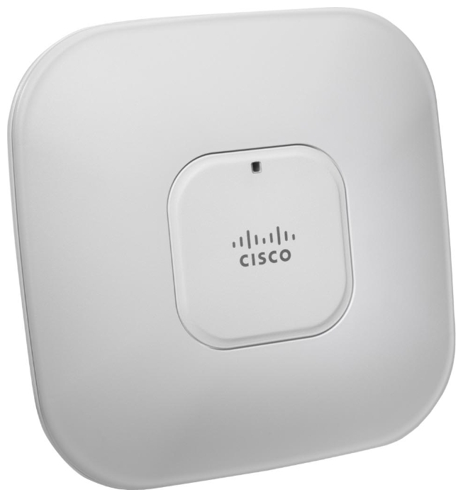
3500i Model
●
Sleek design with internal antennas
●
Ideal for carpeted offices
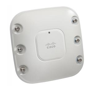
Cisco Aironet 3500e Model
●
Rugged metal housing and extended operating
temperature
●
Ideal for factories, warehouses, and other
indoor industrial environments
●
Versatile RF coverage with external antennas
●
UL 2043 plenum-rated for above-ceiling
installation options or suspended from drop
ceilings
Self-Healing and Self-Optimizing Wireless
●
Classify over 20 different types of interference,
including non-Wi-Fi interference within 5 to 30
seconds
●
Automatic remedial action and less manual
intervention
Secure Interoperability
●
Controller-based Deployment Only
Troubleshooting Forensics for Faster
Interference Resolution and Proactive Action
●
Spectrum Expert Connect provides real-time,
raw spectrum data to help with difficult-to-
diagnose interference problems
●
Air Quality Index provides a snapshot of
network performance and the impact of
interference
●
Historic interference information for back-in-
time analysis and faster problem solving
●
24 x 7 monitoring with remote access reduces
travel and speeds resolution
Robust Security and Policy Enforcement
●
Industry’s first access point with non-Wi-Fi
detection for off-channel rogues
●
Supports rogue access point detection and
detection of denial-of-service attacks
●
Management frame protection detects
malicious users and alerts network
administrators
●
Set policies to prohibit devices that interfere
with the Wi-Fi network or jeopardize network
security
Cisco Aironet 3500 Series Access Point
Cisco
®
Aironet
®
3500 Series Access Points with Cisco CleanAir
technology are the industry’s first
802.11n
access points
to create a
self-healing, self-optimizing wireless network. CleanAir technology is
a systemwide feature of the Cisco Unified Wireless Network that
improves air quality by detecting RF interference that other systems
can’t recognize, identifying the source, locating it on a map, and
then making automatic adjustments to optimize wireless coverage.
These innovative access points provide the highest-performance
802.11n connectivity for mission-critical
mobility
. By intelligently
avoiding interference, the 3500 Series offers performance protection
for 802.11n networks to help ensure reliable application delivery.
RF Excellence
Building on the Cisco Aironet heritage of RF excellence, the 3500
Series delivers industry-leading performance for secure and reliable
wireless
connections. Enterprise-class silicon and optimized radios
deliver a robust mobility experience using Cisco M-Drive technology,
which includes:
●
ClientLink
improves reliability and coverage for legacy clients
●
BandSelect
improves 5-GHz client connections in mixed
client environments
●
VideoStream
uses multicast to improve rich-media
applications
All of these features help ensure the best possible end-user
experience on the wireless network
![]()
GETTING STARTED GUIDE
Cisco Aironet 3502P Lightweight Access Point
1About this Guide
2Safety Instructions
3Unpacking
4Overview
5Configuring the Access Point
6Mounting the Access Point
7Deploying the Access Point on the Wireless Network
8Troubleshooting
9Declarations of Conformity and Regulatory Information
10Configuring DHCP Option 43 and DHCP Option 60
11Access Point Specifications

1 About this Guide
This Guide provides instructions on how to install and configure your Cisco Aironet 3502P Access Point. This guide also provides mounting instructions and limited troubleshooting procedures.
2 Safety Instructions
Translated versions of the following safety warnings are provided in the translated safety warnings document that is shipped with your access point. The translated warnings are also in the Translated Safety Warnings for Cisco Aironet Access Points, which is available on Cisco.com.
|
Warning |
IMPORTANT SAFETY INSTRUCTIONS |
Warning
Warning
Warning
Warning
This warning symbol means danger. You are in a situation that could cause bodily injury. Before you work on any equipment, be aware of the hazards involved with electrical circuitry and be familiar with standard practices for preventing accidents. Use the statement number provided at the end of each warning to locate its translation in the translated safety warnings that accompanied this device. Statement 1071
SAVE THESE INSTRUCTIONS
Only trained and qualified personnel should be allowed to install, replace, or service this equipment.
Statement 1030
Read the installation instructions before you connect the system to its power source.
Statement 1004
This product must be connected to a Power-over-Ethernet (PoE) IEEE 802.3af compliant power source or an IEC60950 compliant limited power source. Statement 353
Installation of the equipment must comply with local and national electrical codes.
Statement 1074
2

|
Warning |
This product relies on the building’s installation for short-circuit (overcurrent) |
||
|
protection. Ensure that the protective device is rated not greater than: |
|||
|
20A. Statement 1005 |
|||
|
Warning |
Do not operate your wireless network device near unshielded blasting caps or in an |
||
|
explosive environment unless the device has been modified to be especially qualified for |
|||
|
such use. Statement 245B |
|||
|
Caution |
The fasteners you use to mount an access point on a ceiling must be capable of |
||
|
maintaining a minimum pullout force of 20 lbs (9 kg) and must use all 4 indented holes |
|||
|
on the mounting bracket. |
|||
|
Caution |
This product and all interconnected equipment must be installed indoors within the same |
||
|
building, including the associated LAN connections as defined by Environment A of the |
|||
|
IEEE 802.af Standard. |
|||
Note The access point is suitable for use in environmental air space in accordance with section 300.22.C of the National Electrical Code and sections 2-128, 12-010(3), and 12-100 of the Canadian Electrical Code, Part 1, C22.1. You should not install the power supply or power injector in air handling spaces.
Note Use only with listed ITE equipment.
3 Unpacking
Follow these steps:
Step 1 Unpack and remove the access point and the accessory kit from the shipping box.
Step 2 Return any packing material to the shipping container and save it for future use.
3

Step 3 Verify that you have received the items listed below. If any item is missing or damaged, contact your Cisco representative or reseller for instructions.
–3502P access point
–Mounting bracket (selected when you ordered the access point)
–Adjustable ceiling-rail clip (selected when you ordered the access point)
4 Overview
The following illustrations show the access point connections and features.
Figure 1 Access Point Ports and Connections (top)
207613
4
|
1 |
2.4-GHz antenna connector B |
4 |
5-GHz antenna connector A |
|||||||||||||||||
|
(labelled with black text) |
(labelled with blue text) |
|||||||||||||||||||
|
2 |
2.4-GHz antenna connector C |
5 |
5-GHz antenna connector C |
|||||||||||||||||
|
(labelled with black text) |
(labelled with blue text) |
|||||||||||||||||||
|
3 |
2.4-GHz antenna connector A |
6 |
5-GHz antenna connector B |
|||||||||||||||||
|
(labelled with black text) |
(labelled with blue text) |
|||||||||||||||||||
|
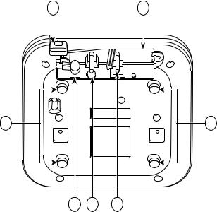
Figure 2 |
Access Point Ports and Connections (bottom) |
|||||||||||||||||||
|
1 |
5 |
|||||||||||||||||||
|
272377 |
|||||
|
2 |
3 |
4 |
|||
|
1 |
Kensington lock slot |
4 |
Console port |
||
|
2 |
Power connection |
5 |
Security padlock and hasp (padlock not |
||
|
included) |
|||||
|
3 |
Ethernet port |
6 |
Mounting bracket pins (feet for desk or |
||
|
table-top mount) |
|||||
5

5 Configuring the Access Point
This section describes how to connect the access point to a wireless LAN controller. Because the configuration process takes place on the controller, see the Cisco Wireless LAN Controller Configuration Guide for additional information. This guide is available on Cisco.com.
The Controller Discovery Process
The 3502P access point uses the IETF standard Control and Provisioning of Wireless Access Points Protocol (CAPWAP) to communicate between the controller and other wireless access points on the network. CAPWAP is a standard, interoperable protocol which enables an access controller to manage a collection of wireless termination points. The discovery process using CAPWAP is identical to the Lightweight Access Point Protocol (LWAPP) used with previous Cisco Aironet access points. LWAPP-enabled access points are compatible with CAPWAP and conversion to a CAPWAP controller is seamless. Deployments can combine CAPWAP and LWAPP software on the controllers.
The functionality provided by the controller does not change except for customers who have Layer 2 deployments, which CAPWAP does not support.
In a CAPWAP environment, a wireless access point discovers a controller by using CAPWAP discovery mechanisms and then sends it a CAPWAP join request. The controller sends the access point a CAPWAP join response allowing the access point to join the controller. When the access point joins the controller, the controller manages its configuration, firmware, control transactions, and data transactions.
For additional information about the discovery process and CAPWAP, see the Cisco Wireless LAN Controller Software Configuration Guide. This document is available on Cisco.com.
CAPWAP support is provided in controller software release 5.2 or later. However, your controller must be running release 7.0.116.0 or later to support 3502P access points.
You cannot edit or query any access point using the controller CLI if the name of the access point contains a space.
Make sure that the controller is set to the current time. If the controller is set to a time that has already occurred, the access point might not join the controller because its certificate may not be valid for that time.
6
Access points must be discovered by a controller before they can become an active part of the network. The 3502P access point supports these controller discovery processes:
•Layer 3 CAPWAP discovery—Can occur on different subnets than the access point and uses IP addresses and UDP packets rather than MAC addresses used by Layer 2 discovery.
•Over-the-air provisioning (OTAP)—This feature is supported by Cisco 4400 series controllers. If this feature is enabled on the controller, all joined access points transmit wireless CAPWAP neighbor messages, and new access points receive the controller IP address from these messages. This feature is disabled by default and should remain disabled when all access points are installed.
Additional information about OTAP is available on Cisco.com at the following link: http://www.ciscosystems.com/en/US/products/ps6366/products_tech_note09186a008093d74a.shtml
•Locally stored controller IP address discovery—If the access point was previously joined to a controller, the IP addresses of the primary, secondary, and tertiary controllers are stored in the access point’s non-volatile memory. This process of storing controller IP addresses on an access point for later deployment is called priming the access point. For more information about priming, see the “Performing a Pre-Installation Configuration” section on page 8.
•DHCP server discovery—This feature uses DHCP option 43 to provide controller IP addresses to the access points. Cisco switches support a DHCP server option that is typically used for this capability. For more information about DHCP option 43, see the “Configuring DHCP Option 43 and DHCP Option 60” section on page 26.
•DNS discovery—The access point can discover controllers through your domain name server (DNS). For the access point to do so, you must configure your DNS to return controller IP addresses in response to CISCO-CAPWAP-CONTROLLER.localdomain, where localdomain is the access point domain name. Configuring the CISCO-LWAPP-CONTROLLER provides backwards compatibility in an existing customer deployment. When an access point receives an IP address and DNS information from a DHCP server, it contacts the DNS to resolve CISCO-CAPWAP-CONTROLLER.localdomain. When the DNS sends a list of controller IP addresses, the access point sends discovery requests to the controllers.
Preparing the Access Point
Before you mount and deploy your access point, we recommend that you perform a site survey (or use the site planning tool) to determine the best location to install your access point.
You should have the following information about your wireless network available:
•Access point locations.
•Access point mounting options: below a suspended ceiling, on a flat horizontal surface, or on a desktop.
7

Note You can mount the access point above a suspended ceiling but you must purchase additional mounting hardware: See “Mounting the Access Point” section on page 12 for additional information.
•Access point power options: power supplied by the recommended external power supply (Cisco AIR-PWR-B), a DC power supply, PoE from a network device, or a PoE power injector/hub (usually located in a wiring closet).
Note Access points mounted in a building’s environmental airspace must be powered using PoE to comply with safety regulations.
Cisco recommends that you make a site map showing access point locations so that you can record the device MAC addresses from each location and return them to the person who is planning or managing your wireless network.
Installation Summary
Installing the access point involves these operations:
•Performing a pre-installation configuration (optional)
•Mounting the access point
•Grounding the access point
•Deploying the access point on the wireless network
Performing a Pre-Installation Configuration
The following procedures ensure that your access point installation and initial operation go as expected. A pre-installation configuration is also known as priming the access point. This procedure is optional.
Note Performing a pre-installation configuration is an optional procedure. If your network controller is properly configured, you can install your access point in its final location and connect it to the network from there. See the “Deploying the Access Point on the Wireless Network” section on page 12 for details.
8
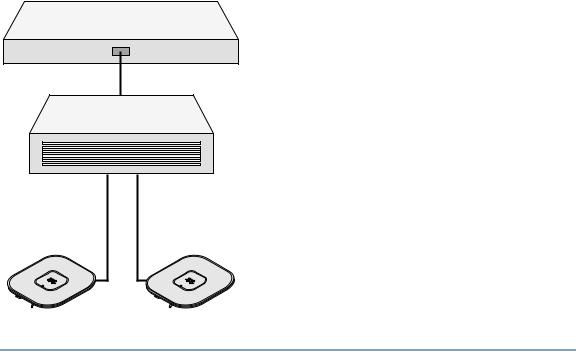
Pre-Installation Configuration Setup
Figure 3 shows the pre-installation configuration setup.
Figure 3 Pre-Installation Configuration Setup
Controller
Layer 3 devices
Cisco Aironet access points
272488
Follow these steps to perform the pre-installation configuration.
Step 1 Make sure that the Cisco wireless LAN controller DS port is connected to the network. Use the CLI, web-browser interface, or Cisco WCS procedures as described in the appropriate Cisco wireless LAN controller guide.
a.Make sure that access points have Layer 3 connectivity to the Cisco wireless LAN controller Management and AP-Manager Interface.
b.Configure the switch to which your access point is to attach. See the Cisco Unified Wireless Network WLAN Controller Guide: Cisco 440x Series WLAN Controllers for additional information.
c.Set the Cisco wireless LAN controller as the master so that new access points always join with it.
d.Make sure DHCP is enabled on the network. The access point must receive its IP address through DHCP.
9
 Loading…
Рейтинг точки доступа:
(4 — 1 голос)
Дать ссылку друзьям:
Рейтинг: Пока без рейтинга
Наличие инструкции подключения и альтернативной прошивки: В наличии
Настройка подключения
На данной странице вы узнаете как подключить Wi-Fi маршрутизатор к компьютеру, а также сможете найти инструкцию по настройке на русском языке.
Сотрудники нашего информационного портала ежедневно обновляют официальные прошивки для той или иной модели устройства.
Настройка Вай-Фай
Пошаговая настройка роутера Cisco AIR-CAP3502I для Ростелеком, Билайн и других интернет провайдеров займет у Вас несколько минут и после этого вы сможете наслаждаться всеми достоинствами Wi-Fi точки доступа Циско.
Настройка IPTV
Если вы хотите получить последнюю версию официальной прошивки и инструкцию по подключению VPN или PPPOE и настройка IPTV телевидения для этого устройства на русском языке на ваш Email, то вам следует оставить полный, развернутый отзыв о той или иной модели Вай-Фай устройства.
Скачать прошивку для маршрутизатораЧтобы скачать прошивку для Cisco AIR-CAP3502I вам достаточно внимательно ознакомиться со страницей, на которой вы сейчас находитесь. Не забывайте оставлять свои отзывы (форма для добавления отзывов находится в нижней части страницы). Если вас не затруднит, то вы можете поделиться ссылкой на прошивку со своими друзьями. Также, если вы не нашли ответ на свой вопрос, то вы можете задать его воспользовавшись формой в нижней части сайта. У нас вы найдете последние версии драйверов для беспроводных устройств. Чтобы скачать новый драйвер, вам необходимо перейти по ссылке «Скачать прошивку», которая расположена чуть ниже.
Скачать прошивку Настройки роутера Видео как настроить Cisco AIR-CAP3502I |
|
More products and manuals for WLAN access points Cisco
| Models | Document Type |
|---|---|
|
AIR-AP1230B-A-K9 |
Datasheet
8 pages |
|
AIR-CAP3502I-EK910 |
Datasheet
6 pages |
|
AIR-LAP1310G-A-K9 |
Datasheet
14 pages |
|
WAP4410N |
Datasheet
5 pages |
|
AIR-AP1142-EK9-5PR |
Datasheet
5 pages |
|
WS-SVC-WISM-1-K9= |
Datasheet
12 pages |
|
AIR-AP1020-I-K9 |
Datasheet
9 pages |
|
AIR-AP1262N-E-K9 |
Datasheet
6 pages |
|
WRP400-G2 |
Datasheet
6 pages |
|
AIR-PI21AG-A-K9 |
Datasheet
8 pages |
|
AIR-AP1121G-J-K9 |
Datasheet
9 pages |
|
AIR-LAP1131G-E-K9 |
Datasheet
12 pages |
|
AIR-BR1310G-A-K9 |
Datasheet
4 pages |
|
WAP4400N-EU |
Datasheet
4 pages |
|
WAP610N-EE |
Datasheet
2 pages |
|
AIR-CAP1552E-E-K9 |
Datasheet
8 pages |
|
AIR-AP1242AG-I-K9 |
Datasheet
6 pages |
|
AIR-LAP1232AG-P-K9 |
Datasheet
8 pages |
|
AIR-PWR-1000= |
Datasheet
9 pages |
|
AIR-LAP1252AG-S-K9 |
Datasheet
7 pages |

1 docs – User Manuals, Help Guides and Specs – for the Cisco AIR-CAP3502I-A-K9 product are present in our data base.
Tips for Finding Manuals:
This web-page provides a list of 1 accessible operating manuals and information books describing Cisco AIR-CAP3502I-A-K9.
All manuals and instructions for Cisco AIR-CAP3502I-A-K9 are introduced in an easy-to-use PDF format and may be gratuitously downloaded or looked through directly from the site.
The page offers the following types of manuals: Wireless Router.
Helpful hints: While selecting a necessary guide for Cisco AIR-CAP3502I-A-K9 one should pay special attention to the type of the document.
We try to supply you with the fullest possible set of papers we or our users are able to find. These may be overviews and specifications of the device, mounting and installing instructions, the unit operating rules and maintenance regulations and much more.
Haven’t found a required manual for your Cisco AIR-CAP3502I-A-K9?
Check in a while. We update our guides collection and add new documents on a daily basis for you to be always able to find the very paper you need on our web-site. In case you own a directory or an instruction for Cisco AIR-CAP3502I-A-K9, which is absent on our site, and you’d like to share it with the public, please send it to us as a scanned copy or a PDF file, and we’ll definitely place it on our page while providing your name as a supplier of the doc. Lots of our users will be grateful for your assistance!
To get access to your Cisco AIR-CAP3502E-A-K9, you need the IP of your device, the username and password. You’ll find such information in the Manual of your Cisco AIR-CAP3502E-A-K9 router. But if you do not have the manual for your router or you do not want to read the whole manual to find the default login information then you can use the quick guide below. To get to the router login page it’s necessary that you are connected to the router.
Cisco AIR-CAP3502E-A-K9 Login Guide
- Open your web browser (e.g. Chrome, Firefox, Opera or any other browser)
- Click HERE to auto detect your router IP. After some seconds our tool will show a link to your router login page. Click on the shown link.
- You should see 2 text fields where you can enter a username and a password.
- Check the bottom of your router. There you will find your login credentials. If not then have a look at the manual of your router.
- Enter the username & password, hit «Enter» and now you should see the control panel of your router.

If above login credentials doesn’t work with your Cisco AIR-CAP3502E-A-K9 router then try this method
Try different ID/password combinations that are widely used by Cisco that you’ll find below. In this list are the most popular default username and password combinations used by Cisco. Sometimes the username and password doesn’t work that we mentioned in the top of this guide. Then you can try these username/password combinations below to get access to your Cisco AIR-CAP3502E-A-K9 wireless router.
| # | Username | Password |
| 1 | Cisco | Cisco |
| 2 | admin | admin |
| 3 | (blank) | (blank) |
| 4 | admin | password |
| 5 | admin | (blank) |
| 6 | (blank) | Cisco |
| 7 | admin | changeme |
| 8 | root | attack |
| 9 | (blank) | |
| 10 | sa | (blank) |
| 11 | ATTadmin | 401!VEN |
| 12 | bbsd-client | changeme2 |
| 13 | cusadmin | highspeed |
| 14 | admin | cisco |
| 15 | user | (blank) |
| 16 | Administrator | changeme |
| 17 | admin | 1PTV-ADM1N |
| 18 | bbsd-client | NULL |
| 19 | Administrator | admin |
| 20 | (blank) | admin |
| 21 | (blank) | riverhead |
| 22 | (blank) | public/private/secret |
| 23 | superuser | superuser |
| 24 | c | |
| 25 | ILMI | |
| 26 | admin | system |
| 27 | hsa | hsadb |
| 28 | (blank) | _Cisco |
| 29 | root | blender |
| 30 | admin | W2402 |
| 31 | (blank) | W2402 |
| 32 | root | secur4u |
| 33 | cmaker | |
| 34 | EAdmin<systemid> | (blank) |
| 35 | Admin123 | Admin123 |
| 36 | prixadmin | prixadmin |
| 37 | uwmadmin | password |
| 38 | admin | diamond |
| 39 | cusadmin | cusadmin |
| 40 | End User | 7936 |
| 41 | cable-docsis | |
| 42 | admin | tsunami |
| 43 | admin | |
| 44 | (blank) | 233897301 |
| 45 | (blank) | changeit |
| 46 | admin | default |
| 47 | bubba | (unk) |
| 48 | cmaker | cmaker |
| 49 | admin | telstra |
| 50 | n/a | (blank) |
| 51 | netrangr | attack |
Default login IPs for my Cisco router
You tried different router IPs but nothing worked? Did you try the following IPs? In the list below we listed all known router IPs for the manufacturer Cisco. Maybe this will work for you.
| # | Default Router IP |
| 1 | 192.168.1.1 |
| 2 | 192.168.0.1 |
| 3 | 10.10.10.1 |
| 4 | 10.0.0.1 |
| 5 | 192.168.1.245 |
| 6 | 192.168.100.1 |
| 7 | 192.168.1.254 |
| 8 | 192.168.15.1 |
| 9 | acquired via DHCP |
| 10 | 192.168.1.115 |
| 11 | 10.1.10.1 |
| 12 | 192.168.0.0 |
| 13 | 192.168.10.10 |
| 14 | 10.128.128.128 |
| 15 | 10.0.0.2 |
| 16 | 192.168.75.1/setup |
Manuals for Cisco AIR-CAP3502E-A-K9
Nothing of the methods worked for me and I still not get access to my Cisco !
All you need to do is to reset your modem. This can be done easily by clicking on the reset button at the back or at the bottom of your router. If you hold down this small button for approximately 20 seconds, (you may have to use a toothpick), then your modem will get restored to the factory settings. What you need to keep in mind is that when you reset your modem, you will lose your connection online. It is therefore better to take an expert’s assistance in this regard. Note: If you have not enough information, it is obviously recommended that you should get help from a person who has all the knowledge about this topic.