
- Home
- Инструкции
- Автоматика для ворот
- CAME
- ZF1

| CAME ZF1 инструкция | |
|---|---|
| Тип инструкции: | Руководство по установке и использованию |
| Категория: | Автоматика для ворот CAME |
| Язык: | Русский |
| Размер: | 252.5 Kb |
| Формат файла: | |
| Дата добавления: | 06.08.2013 |
Отзывы по оборудованию и комментарии к материалу
Ответить 04.07.2018 06:06
РАДИК
Как подключить две пары фотоэлементы на распашные ворота.т.е одни на открытие другие на закрытие плата ZF 1
Ответить 26.01.2019 11:18
Владимир Петров
Ворота перестали закрываться (CAME3000/ZF1)/ При нажатии кнопки брелка слышно срабатывание реле, но ворота даже не дёргаются. Часто мигает красный светодиод на плате. Предохранители целы. Фото-приёмники чистые.
Что могло случиться и как отремонтировать?
Ответить 07.03.2020 20:15
Сергей
Владимир Петров, возможно, что вода попала в привод, и не хватает усилия для открытия. От погоды зависит?
Ответить 23.09.2020 03:59
Игорь Арбузов
Одна створка(правая) к утру постоянно открыта на 15-20 см. Если обесточить блок управления, то створка сама не открывается, ворота остаются плотно закрыты. Днем, пока ворота часто работают, все четко. Как исправить?
Ответить 27.01.2022 12:43
Андрей
Z1F питание приводов 24в???
Ответить 28.01.2022 20:54
Creator
Андрей, Блок управления предназначен для управления приводами переменным напряжением 220В, мощностью до 320 Вт.
Ответить 11.07.2022 09:35
Марат
Обе створки открывается. А закрывается только одна
Ответить 24.07.2022 14:01
Creator
Проверьте настройку «Время задержки второго привода при закрывании» (DELY 2W или T.R.2M.). Возможно неисправно одно из реле на плате управления.

Блоки управления
- Блоки управления для двигателей 220 В
- Блоки управления для двигателей 380 В
- Блоки управления для двигателей 24 В
- Резервное питание для двигателей 24 В
Инструкции по монтажу
- Распашные ворота
- Откатные ворота
- Гаражные ворота
- Промышленные ворота
- Автоматические шлагбаумы
- Парковки и цепные барьеры
- Автоматика для дверей
- Блоки управления
- Радиоуправление
- Устройства управления
- Устройства безопасности
- Турникеты
- Контроль доступа
- Оконная автоматика MOWIN
Главная
- КОМПЛЕКТЫ CAME
- Автоматика для распашных ворот
- Автоматика для ворот откатного типа
- Автоматика для гаражных ворот
- Автоматика для промышленных ворот
- Автоматические шлагбаумы
- Парковки и цепные барьеры
- Автоматические двери
- Турникеты
- Аксессуары управления
- Аксессуары безопасности
- Радиоуправление
- Системы управления паркингом PS ONE
- Запасные части САМЕ
- Комплектующие CAME для изготовления ворот
- Блокираторы URBACO
- Комплектующие Comunello для изготовления ворот
- Домофоны BPT
- Автоматика для окон Comunello MOWIN
- Инструкции по монтажу
- Сертификаты САМЕ
- ИНТЕРНЕТ-МАГАЗИН
- —————————
- ЦЕНЫ
- Техподдержка
- Новости
- Видео
- Акции
- Доставка
- Статьи
- Сервисный центр
- Контакты

![]()
![]()
|
SERIE Z | Z SERIES | |
SÉRIE Z | BAUREIHE Z | SERIE Z |
Documentazione |
|
Tecnica |
||
|
SCHEDA COMANDO |
T16 |
|
|
CONTROL BOARD |
ZF1 |
|
|
CARTE DE COMMANDE |
rev. 0.1 |
|
|
STEUERPLATINE |
11/2002 |
|
|
TARJETA DE MANDO |
CANCELLI |
|
|
© CAME |
||
|
PER U1800 |
AUTOMATICI |
|
|
CANCELLI AUTOMATICI |
319T16 |
|
ITALIANO
DESCRIZIONE TECNICA SCHEDA COMANDO ZF1
Descrizione
La scheda deve essere alimentata a 230V (a.c.) sui morsetti L1 e L2, ed é protetta in ingresso con un fusibile da 5A, mentre gli accessori a bassa tensione (24V) sono protetti con fusibile da 3.15A.
La potenza complessiva degli accessori (24V) non deve superare i 20W.
Sicurezza
Le fotocellule possono essere collegate e predisposte per:
—Riapertura in fase di chiusura (2-C1), le fotocellule rilevando un ostacolo durante la fase di chiusura del cancello, provocano l’inversione di marcia fino alla completa apertura;
—Stop totale (1-2), arresto del cancello con l’esclusione del ciclo di chiusura automatica, per riprendere il movimento del cancello, agire sulla pulsantiera o sul radiocomando;
Accessori opzionali
—Elettroserratura 12V (ES-ES);
—Lampada spia cancello aperto (3W max.). Lampada che segnala la posizione di apertura del cancello, si spegne quando il cancello è a fine tempo lavoro chiude (5-10).
Altre funzioni
— Chiusura automatica. Il temporizzatore di chiusura automatica si autoalimenta a fine tempo lavoro apre. Il tempo prefissato regolabile, è in ogni modo subordinato dall’intervento di eventuali accessori di sicurezza e si esclude dopo un intervento di «stop» o in mancanza d’energia elettrica;
—«Uomo presente«. Funzionamento del cancello mantenendo premuto il pulsante (esclude la funzione del radiocomando). Si abilita quando il trimmer T.L. è regolato al minimo.
Regolazioni
—Tempo chiusura automatica;
—Tempo ritardo chiusura del 2° motore;
—Tempo lavoro.
ATTENZIONE: prima di intervenire all’interno dell’apparecchiatura,
togliere la tensione di linea
ENGLISH
TECHNICAL DESCRIPTION ZF1 CONTROL BOARD
Description
The board must be powered at 230V (a.c.) on the L1 and L2 terminals, and the inlet is protected with a 5A fuse, while the low voltage (24V) accessories are protected with a 3.15A fuse.
The accessorie’s total capacity (24V) should not exceed 20W.
Safety
Photocells can be connected to abtain:
—Re-opening during closure (2-C1), if the photocells identify an obstacle while the gate is closing, they will reverse the direction of movement until the gate is completely open;
—Total stop (1-2), shutdown of gate movement without automatic closing, a pushbutton or radio remote control must be actuated to resume movement.
Optional accessories
—12V Electric lock (ES-ES);
—Open gate pilot lamp (3W max.). Lamp that signals the gate is open, turns off when the time fixed for the gate’s closing has elapsed (10-5).
Other functions
—Automatic closing. The automatic closing timer is automatically activated at the end of the opening cycle. The preset, adjustable automatic closing time is automatically interrupted by the activation of any safety system, and is deactivated after a STOP command or in case of power failure;
—«Operator present«. Gate operates only when the pushbutton is held down (the radio remote control system is deactivated). It is activated when the T.L. trimmer is set to the minimun.
Adjustments
—Automatic closure time;
—Delay in closing of the M2 motor;
—Operating time.
IMPORTANT: Shut off the mains power before servicing the inside of the unit.
FRANÇAIS
DESCRIPTION TECHNIQUE CARTE DE COMMANDE ZF1
Description
La carte doit être alimentée à 230V (c.a.) sur les bornes L1 et L2 et est protégée à l’entrée par un fusible de 5A, tandis que les accessoires en basse tension (24V) sont protégés par un fusible de 3.15A.
La puissance totale des accessoires (24V) ne doit pas dépasser 20W.
Sécurité
Accessoires en option
—Serrure électrique 12V (ES-ES);
—Voyant grille ouverte (3W max.).Voyant qui signale la position d’ouverture de la grille et s’éteint quand la grille a fini de se refermer (10-5).
Autres fonctions
|
Il est possible de brancher des |
— Fermeture automatique. Le tempo- |
||||
|
risateur de fermeture automatique est |
|||||
|
photocellules et de les programmer pour: |
|||||
|
autoalimenté à la fin du temps de la |
|||||
|
— Réouverture en phase de fermeture (2- |
|||||
|
course en ouverture. Le temps réglable |
|||||
|
C1), les cellules |
photoélectriques |
||||
|
provoquent l’inversion de marche jusqu’à est programmé, cependant, il est |
|||||
|
l’ouverture complète si elles relèvent un |
subordonné à l’intervention d’éventuels |
||||
|
obstacle durant la phase de fermeture |
accessoires de sécurité et il est exclu |
||||
|
après une intervention de “stop” ou en |
|||||
|
du portail; |
|||||
|
cas de coupure de courant; |
|||||
|
— Stop total |
(1-2), |
arrêt du |
portail |
et |
|
|
— Fonction “homme mort” . Fonc- |
|||||
|
désactivation |
d’un éventuel |
cycle |
de |
||
|
tionnement du portail en maintenant |
|||||
|
fermeture automatique; pour activer de |
|||||
nouveau le mouvement, il faut agir sur
appuyé le bouton-poussoir (exclut la
les boutons-poussoirs ou sur la radiocom-
fonction de la radiocommande).Il s’active
mande.
quand le compensateur T.L. est réglé au minimum.
Reglages
—Temps de fermeture automatique;
—Retard fermeture moteur 2;
—Temps de fonctionnement.
ATTENTION: avant d’intervenir à l’intérieur del’appareillage, couper la tension de ligne
DEUTSCH
TECHNISCHE BESCHREIBUNG STEUERPLATINE ZF1
Beschreibung
Die Karte muß über die Klemmen L1 und L2 mit 230 V AC gespeist werden und ist am Eingang durch 5 A Sicherungen geschützt.
Das Niedrigspannungszubehör (24 V) dagegen ist durch 3,15 A Sicherungen geschützt.
Die Gesamtleistung der Zubehörteile (24V) darf 20W nicht übersteigen.
Sicherheitsvorrichtungen
Die Lichtschranken können für folgende Funktionen angeschlossen bzw. vorbereitet werden:
—Wiederöffnen beim Schließen (2-C1), die Lichtschranken ermitteln ein Hindernis während des schließens vom Tor und lösen die Umkehr der Laufrichtung vom Tor aus, bis dieses wieder vollständig geöffnet ist;
—Totalstop (1-2), sofortiger Stillstand des Tores mit Ausschluß eventueller Schließautomatik: Fortsetzung des Torlaufs über Drucktasterbzw. Funksendersteuerung.
Extrazubehör
—Elektroschloß 12V (ES-ES);
—Kontrollleuchte Tor offen (3W max.). Die Kontrollleuchte zeigt an, daß das Tor offen ist und schaltete sich ab, wenn das Tor nach Arbeitsende geschlossen wird (10-5).
Einstellungen
—Zeit für das automatische Schließen;
—Schließverzögerung Motor 2;
—Laufzeit.
Andere wahlfunktionen
—Schließautomatik . Der Schließ- automatik-Zeischalter speist sich beim Öffnen am Ende der Torlaufzeit selbst . Die voreingestellte Zeit ist auf jeden Fall immer dem Eingriff eventueller Sicherheitsvorrichtungen untergeordnet und schließt sich nach einem “Stop”- Eingriff bzw. bei Stromausfall selbst aus;
—Funktion “Bedienung vom Steuerpult”. Torbetrieb durch Drucktasterbetätigung (Funkfernsteuerung ausgeschlossen). Wird dann eingeschaltet, wenn der Trimmer T.L. auf das Minimum gestellt ist.
ACHTUNG: Das Gerät vor Eingriffen
im inneren spannungsfrei schalten
2

ESPAÑOL
DESCRIPCIÓN TÉCNICA TARJETA DE MANDO ZF1
Descripción
La tarjeta se debe conectar a 230V (c.a.) en los bornes L1 y L2, y está protegida a la entrada con un fusible de 5A, mientras que los accesorios de baja tensión (24V) están protegidos con un fusible de 3,15A.
La potencia total de los accesorios (24V) no tiene que superar los 20W.
Seguridad
Las fotocélulas pueden estar conectadas y predispuestas para:
—Reapertura en la fase de cierre (2-C1), las fotocélulas detectan un obstáculo durante el cierre de la puerta, provocando la inversión de marcha hasta la apertura completa;
—Parada total (1-2), parada de la puerta excluyendo el posible ciclo de cierre automático; para reactivar el movimiento es preciso actuar en el teclado o en el mando a distancia.
|
Accesorios opcionales |
Regulaciones |
|
— Cerradura eléctrica 12V (ES-ES); |
— Tiempo de cierre automático; |
|
— Indicador luminoso cancela abierta |
— Retraso cierre motor 2; |
|
(3W max.). Indicador luminoso que in- |
— Tiempo trabajo. |
|
dica la posición de apertura de la |
|
|
cancela; se apaga cuando la cancela |
|
|
llega al final del tiempo de cierre (10-5). |
Otras funciónes
—Cierre automático. El temporizador de cierre automático se autoalimenta en fin- de-tiempo carrera en fase de apertura. El tiempo prefijado regulable, sin embargo, está subordinado a la intervención de posibles accesorios de seguridad y se excluye después de una intervención de parada o en caso de falta de energía eléctrica;
—Función a «hombre presente». Funcionamiento de la puerta manteniendo pulsada la tecla (excluye la función del mando a distancia). Se activa cuando el trimmer T.L. está regulado en el mínimo.
ATENCION: antes de actuar dentro del aparado, quitar la tensión de línea
SCHEDA BASE // MOTHERBOARD // CARTE BASE // GRUNDPLATINE // TARJETA BASE
1Morsettiere di collegamento
2Fusibile di linea 5A
3Fusibile accessori 3.15A
4Pulsante memorizzazione codice radio
5Trimmer di regolazione ritardo del 2° motore
6Trimmer di regolazione tempo lavoro
7Trimmer di regolazione tempo di chiusura automatica
8Selettore funzioni a 2 dip
9Innesto scheda radiofrequenza 10 LED segnalazione
1Terminal block for external conections
2Line fuse, 5A
3Fuse on accessory power line, 3.15A
4Radio-code save button
5Trimmer for adjustment delay on closing cycle — motor 2
6Trimmer for adjustment operating time
7Trimmer for adjustment automatic closing
82-dip function switch
9Socket AF radiofrequency board 10 Signal LED
|
2 |
||||
|
3 |
||||
|
4 |
PROG |
|||
|
5 |
||||
|
6 |
1 |
2 |
||
|
7 |
8 |
9 |
10 |
1 |
|
PRINCIPAUX COMPOSANTS |
F |
HAUPTKOMPONENTEN |
D |
PRINCIPALES COMPONENTES |
E |
|||||
|
1 |
Plaque à bornes de connexion |
1 |
AnschlußKlemmenleiste |
1 |
Caja de bornes para las |
|||||
|
2 |
Fusible de ligne 5A |
2 |
Hauptsicherung 5A |
2 |
conexiónes |
|||||
|
3 |
Fusible accessoires 3.15A |
3 |
Zubehör-Sicherung 3.15A |
Fusible de línea 5A |
||||||
|
4 |
Bouton-poussoir mémorisation code |
4 |
Knöpfe zum Abspeicher der |
3 |
Fusible accesorios 3.15A |
|||||
|
5 |
radio |
5 |
Radiocode |
4 |
Tecla de memorización del código |
|||||
|
Trimmer de réglage retard |
Trimmer zur Einstellung |
5 |
radio |
|||||||
|
6 |
fermeture moteur 2 |
6 |
Schließverzögerung Motor 2 |
Trimmer de regulación retraso |
||||||
|
Trimmer de réglage temps de |
Trimmer zur Einstellung Laufzeit |
6 |
cierre motor 2 |
|||||||
|
7 |
fonctionnement |
7 |
Trimmer zur Einstellung der |
Trimmer de regulación tiempo |
||||||
|
Trimmer de réglage fermeture |
8 |
Schließautomatik |
7 |
trabajo |
||||||
|
8 |
automatique |
Wählschalter für Funktionen mit 2 |
Trimmer de regulación tiempo |
|||||||
|
Selecteur de fonctions à 2 |
9 |
Dip |
8 |
cierre automático |
||||||
|
interrupteurs à positions multiples |
Steckanschluß Funkfrequenze- |
Selector de funciones con 2 dip |
||||||||
|
9 |
Branchement carte radiofréquence |
10 |
Platine AF |
9 |
Conexión tarjeta radiofrecuencia |
|||||
|
10 |
AF |
LED Kontrolleuchte zur Anzeige |
10 |
AF |
||||||
|
LED de signalisation |
LED Kontrolleuchte zur Anzeige |
3

|
COLLEGAMENTI ELETTRICI // ELECTRICAL CONNECTIONS // BRANCHEMENTS ÉLECTRIQUES |
// ELEKRISCHE ANSCHLÜSSE |
// CONEXIONES ELÉCTRICAS |
||
|
L1 L2 |
U V W X Y E |
5 C1 7 2 |
1 11 10ESES |
L1 
L2 
U
W
V
X
W
Y
W 
E
5
10 
2
7
2
C1
1
2
Alimentazione 230V (a.c.)
230V (a.c.) power input
Alimentation 230V (c.a.)
Stromversorgung 230V (Wechselstrom)
Alimentación 230V (a.c.)
Motore “1” monofase 230V (a.c.) ritardato in apertura
Motor “1” single-phase 230V (a.c.) delayed opening
Moteur “1” monophasé 230V (c.a.) retardé en ouverture
Motor “1” 230V (Wechselstrom) Einphasenmotor mit Verzögerung beim Öffnen
Motor “1” monofásico 230V (a.c.) retardado durante la apertura
|
Motore “2” monofase 230V (a.c.) ritardato in chiusura |
* |
|
Motor “2” single-phase 230V (a.c.) delayed closure |
|
|
Moteur “2” monophasé 230V (a.c.) retardé en fermeture |
|
|
Motor “2” 230V (Wechselstrom) Einphasenmotor mit Verzögerung beim Schließen |
|
|
Motor “2” monofásico 230V (a.c.) retardado durante el cierre |
|
|
Uscita 230V (a.c.) in movimento (es. lampeggiatore — max. 25W) |
|
|
230V (a.c.) output in motion (e.g. flashing light — max. 25W) |
|
|
Sortie 230V (c.a.) en mouvement (ex. branchement clignotant — max. 25W) |
|
|
Ausgang 230V (Wechselstrom) in Bewegung (z.B. Blinker-Anschluß — max. 25W) |
|
|
Salida de 230V (a.c.) en movimento (p.ej. conexión lámpara intermitente — |
|
|
max. 25W) |
|
|
Lampada spia (24V-3W max.) «cancello aperto» |
|
|
(24V-3W max.) «gate-opened» signal lamp |
|
|
Lampe-témoin (24V-3W max.) «portail ouverture» |
|
|
Signallampe (24V-3W max.) «Tor Öffnen» |
|
|
Lámpara indicadora (24V-3W max.) «puerta abierta» |
|
|
Contatto (N.O.) radio e/o pulsante per comando (vedi dip 2) |
|
|
(N.O.) contact radio and/or button for control (see dip 2) |
|
|
Contact (N.O.) radio et/ou poussoir pour commande (voir dip 2) |
|
|
Funkkontakt (Arbeitskontakt) und/oder Taste Steuerart (sehen dip2) |
|
|
Contacto (N.O.) radio y/o pulsador para mando (mirar dip 2) |
|
|
Contatto (N.C.) di «riapertura durante la chiusura» |
|
|
Contact (N.C.) for «re-opening during the closing» |
|
|
Contact (N.F.) de «réouverture pendant la fermeture» |
|
|
Kontakt (Ruhekontakt) «Wiederöffnen beim Schliessen» |
|
|
Contacto (N.C.) para la «apertura en la fase de cierre» |
|
|
Pulsante stop (N.C.) |
|
|
Pushbutton stop (N.C.) |
|
|
Bouton-poussoir arrêt (N.F.) |
|
|
Stop-Taste (N.C.) |
|
|
Pulsador de stop (N.C.) |
*= per i collegamenti elettrici dei motoriduttori consultare documentazione tecnica S81 pag.8 e 9
*= for the electrical connections of the gear motors, consult the technical documentation S81 on pages 8 and 9
*= pour les branchements électriques des motoréducteurs, consulter la documentation technique S81 pages 8 et 9
*= für die elektrischen Anschlüsse der Getriebemotoren ist die technische Dokumentation S81, Seiten 8 und 9, einzusehen
*= para las conexiones eléctricas de los motorreductores consulte la documentación técnica S81 págs. 8 y 9
4
 Loading…
![]()
CAME ZF1 Блок управления — Инструкция по установке и эксплуатации в формате pdf. Руководства по установке, настройке и эксплуатации оборудования.
Дата добавления: 29.08.2009
Размер файла: 252.5Kb
Формат файла: pdf
Просмотров: 10659
Загрузок: 2158
Дополнительная информация
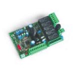
Блок управления приводами для распашных ворот CAME — ZF1
Производитель: CAME (Италия)
Блок управление автоматикой для распашных ворот 220В. – ZF1 (функция электрозамка)
Применение: для автоматики распашных ворот CAME – Crono310, ATI3000, ATI5000, FERNI 1000
Инструкция по установке и эксплуатации
Отзывы и комментарии
Отзывы и комментарии к материалу «CAME ZF1 Блок управления — Инструкция по установке и эксплуатации».

ПОДРОБНЕЕ
Блок управления ZF1N разработан для управления приводами САМЕ для распашных ворот, установленных в частных жилых домах и жилых комплексах.
Технические характеристики модель ZF1N
Полную иснтрукцию по подключению можно скачать во вкладке ИНСТРУКЦИИ.
В памяти можно сохранить до 50 кодов пользователей.
Для добавления пульта нового пользователя необходимо:
