
Table of Contents: AURATON 2020 Thermostat Owner’s Manual
-
AURATON 2020 18.4 Diagram of direct AURATON 2020 connection to a gas boiler independent on power supply, without the circulation pump red electromagnetic valve of the gas boiler connector cube socket supply ~230V / = 12V AURATON 2020 AURATON 2020 — Connection diagrams 56 EN
-
After a certain time, for example one or several days, a week, or a month, shortly press the FILTER button again. The display will then show an integer number of the hours during which the heating was switched on (since the last reset). Comparison of the heating duration with total time elapsed since the reset allows for determining the ratio of real heating to idle time of the heating device. Maximal number of accounted hours amounts to 999. When the time measured exceeds 250 hours a FILTER indication starts blinking, thus reminding of the need to check or reset the meter. Once t
-
9. Working time meter of the heating device The heating device while heating the rooms does not operate continuously. It means that the delivery of energy is interrupted. In some cases the information of total number of operation hours of the heating device e.g. within a week or month would be very helpful. AURATON 2020 and AURATON 2020 TX RX Plus are provided with a heating time meter, showing integer number of heating hours (the indicator ‘3’ is then lit at the display). In order to use the function the meter should be previo
-
AURATON 2020 AURATON 2020 AURATON 2020 TX RX Plus Preliminary notes The manual includes the information on AURATON 2020 and AURATON 2020 TX RX Plus controllers. Operation of both the controllers is identical; therefore the whole information is placed in a single chapter. The information related to their installation is placed in separate sections of the manual. AURATON 2020 TX Plus enables independent modification of the protection code of the RX receiver communication. The controller is programmed in the factory to 085 code number. Ne
-
AURATON 2020 12. Acquaintance with the AURATON 2020 RX Plus 12.1 Outer view 1. An extensible antenna – for communication with the AURATON 2020 RX Plus controller. 2. Control diodes the green diode – informs that the executing device (e.g. a furnace) is operative. the red diode – informs whether the AURATON 2020 RX Plus controller is supplied the yellow diode – indicates the radio connection with temperature controller of AURATON 2020 RX Plus 3. The switch of the additional socket. 4. The additional socket –
-
2. Set the temperature to be maintained during our absence, e.g. 17ºC, using the appropriate buttons. 3. Pressing the buttons DAY HOUR MIN (in the intervals shorter than 10 seconds) adjust the day and time of restoring the automatic (programmed) operation. In this example it could be Sunday, 2:00 p.m. It means that the controller should resume its automatic operation 6 hours prior to our planned arrival and temperature of the rooms should grow accordingly. Note 1. The automatic operation may be resumed anytime by pressing AUTO. 2. Th
-
AURATON 2020 4. Setting the controller AURATON 2020 AURATON 2020 TX Plus 4.1 Adjustment of the day of the week (No 2 at the display) 1. Move the battery cover to the right. 2. Repeat pressing the DAY pushbutton until proper day of the week appears at the display, according to the point 2.2. 4.2 Setting the clock (No 1 at the display) 1. Move the battery cover to the right. 2. Repeat pressing the HOUR pushbutton until proper hour appears at the display. 3. Repeat pressing the MIN pushbutton until proper minute appears at the display. 4. Slide
-
1. Installation of AURATON 2020 Note: During installation of the controller the power supply should be switched off. It is recommended to charge a specialist company with the installation. 1.1 A choice of proper location of the AURATON 2020 controlle Appropriate operation of the controller strongly depends on its location. The location without air circulation or in a directly insolated place results in inappropriate control of temperature. In order to ensure proper operation of the controller place it on an internal wall of the building (between the rooms). A place of u
-
18.3 Diagram of direct AURATON 2020 connection to an electric device of the power below 230V and 5A max ~ 230V, 5A max ~ 230V AURATON 2020 a heating device 55 EN AURATON 2020 — Connection diagrams
-
AURATON 2020 4. Press the buttons (no later than 10 seconds after setting the hour and minutes) in order to adjust the temperature that the controller should maintain since the previously set time. The temperature may be adjusted in the range from 5ºC to 27ºC with the accuracy of 0.5ºC. 5. Press PROG again (no later than 10 seconds after the previous opera- tion). The display will be as follows: The indicator of the Program 2 blinks, which means that it is to be set. 6. Proceed according to the
-
AURATON 2020 11. Installation AURATON 2020 TX RX Plus Auraton 2020 TX is a wireless controller. It means that it (TX — transmitter) communicates with heating device throught receiver (RX — reciver) by radio waves. Installation is limited to connection of receiver with controlled device only. The only installation operation includes connection of the AURATON 2020 RX Plus receiver to the executing device (e.g. a furnace). 11.1 Cable connection to AURATON 2020 RX Plus Note: During installation of the RX controller the power supply should be
-
AURATON 2020 2. Acquaintance with the AURATON 2020 AURATON 2020 TX Plus 2.1 Outer view The AURATON 2020 and AURATON 2020 TX Plus are programmable controllers. They are able to adjust the room temperature to the desired level 4 times within 24 hours, from Monday to Friday, and twice within 24 hours on Saturdays and Sundays. This enables very accurate defining the temperature cycle within the working week, when activity of inmates is increased, and in weekends, during a rest time. It allows for programming with one-minute accuracy. At the front panel of the controller a slidable cover is locate
-
(*) Note: The controller may cooperate with an electric, gas, or oil device of the power exceeding load capacity of the terminals only through an intermediate switch of the power and operation suitable for the end device. In such a case please consult the dealer or guarantor. Specialist data: The executing relay. It is a two-state self-sustaining relay with. For the standard setting of the micro-switch slider (slider 1 – bottom position) it has the following states: 1. for act
-
19. Technical specification 1. The range of temperature measurement 0÷40ºC (graduation 0.25ºC) 2. The range of temperature control 5÷27ºC (graduation 0.25ºC) 3. Accuracy of indication +/-1ºC 4. Accuracy of the clock ± 70 seconds/per month 5. Programs 4 on working days, 2 on Saturday, 2 on Sunday 6. Sensitivity of temperature control 0.5ºC, 1ºC, or 2ºC (adjusted in the factory to 1ºC) 7. Control mode Heating 8. Admissible load of the terminals (*) 230
-
AURATON 2020 3. Using the pushbuttons set a new communication code in the range from 1 to 255 and acknowledge it by pressing RETURN. 4. The yellow diode » » of the AURATON 2020 RX Plus receiver should blink several times which means that the new code is recorded. 5. If the changed code gives no improvement of the communication between the AURATON 2020 TX Plus controller and AURATON 2020 RX Plus receiver the code should be changed again. 17. Support of the AURATON 2020 TX Plus controller The set is includes a plastic support o
-
18.2 Diagram of direct connection of | AURATON 2020 P provided with a floor sensor Note: In case of the use of a controller provided with a floor sensor (i.e. AURATON 2020 P) the following operations should be made: a branch box provided with a connector cube should be installed about 30cm above the floor level; a shield pipe should be designed and laid in the hollow previously made in the wall and floor. The pipe should be flushed with the mat or heating conducts (min 50 cm) a
-
AURATON 2020 14. Protection 1. Should any transmission disturbance due, for example, to a strong electromagnetic impulse or voltage drop of AURATON 2020 TX Plus battery, prevent the AURATON 2020 RX Plus receiver from confirming the ON or OFF switching within 5 consecutive cycles (i.e. 5 minutes) the heating device switches off. This is to avoid overheating of the device. After elimination of the reason of such a disturbance the controller resumes its normal operation. Only in case of battery replacement reprogramming of AURATON 2020 TX Plus may be required, should the ope
-
AURATON 2020 Note: The yellow control light of the receiver confirms transmitter signal reception. It is lit for one second every minute. The reasons of missing signal may be as follows: 1. Excessive distance between transmitter and receiver (reduce the distance). 2. Replace used batteries of AURATON 2020 TX Plus with new alkaline ones. In some cases the batteries should be replaced in spite that the low battery indicator is not yet lit. The green diode signalizes switching the boiler (or another device) on. 16. Communication problems. Setting a new communi
-
AURATON 2020 1.2 Conductor terminals of AURATON 2020 The conductor terminals may be accessed after removing the cover of the front controller panel, batteries, and 2 screws fixing the protection plate. There are three terminals, marked by COM, NO, and NC. This is a typical unipole two-state relay. 1.3 Assembly of the AURATON 2020 controller The controller is assembled with the help of a pattern. Bore two holes of the diameter of 6mm in the wall. Drive the bolts and tighten the controller with screws, the left-hand screw longer than the right-hand one. Not
-
AURATON 2020 3. Putting the controller into operation Once the batteries are installed, the controller starts operation with its default parameters. It means that the following information will be displayed: Time: 00:00 (midnight) Day: MO (Monday) Temperature indicator: current room temperature Program: 2 (initiated on Sunday and lasting until 6:00 a.m. on Monday). Temperature settings: PROG1: from 6:00 a.m. 21ºC PROG2: from 8:30 a.m. 21ºC PROG3: from 4:00 p.m. 21ºC PROG4: from 11:00 p.m. 17ºC MO PROG : 2 0 C It means that from 6:00 a.m. to 8:2
-
AURATON 2020 Example 3 The PROG button pressed 9 times returns the operation to the first program for working days. In order to avoid a mistake observe the indicators ‘2’ and ‘4’ according to the display description in the point 5.2. The programming is completed by pressing RETURN or waiting 10 seconds without pressing any key. B) It is possible to program all 8 temperatures to the same value, e.g. 21ºC. In such a case the equal temperature is maintained the whole week through, irrespective of the hours of theoretical switching between the temperatures (no need to change the switching time while programming). C) Programming sequen
-
AURATON 2020 1. AURATON 2020 RX Plus (receiver). 2. AURATON 2020 TX Plus located in any room. Note: In case of most of the heating device the short-circuit connector of the connection cube should be removed and replaced with the receiver wires. In case of any doubts please contact the dealer or manufacturer. 1 2 18.5 Diagram of direct AURATON 2020 RX Plus connection to a heating device NO COM NC AUTO MAN TH PROG : 0 C a heating device for example a gas furnace 57 EN AURATON 2020 TX RX Plus — Connection diagrams
-
AURATON 2020 At the left-hand side there are — two triangular buttons for temperature setting ; — two pushbuttons: AUTO (automatic control), MAN (manual control) alternating the controller operation mode between automatic or manual; — a large multi-function display LCD. The cover may be removed in order to exchange the batteries. Once it is removed the access to 2 R-6 batteries is opened. 2.2 Display 1. The time is displayed in 24-hours system. 2. English abbreviations of the days of the week indicate the current day. 3. A bar indicating switching on the heating device. 4. The digits indicate the currently operating program. PR
-
AURATON 2020 5. Manual operation Short pressing the MAN button causes that the controller ceases execution of the program and resumes manual operation. The symbol » » appears on the display. Required temperature, to be maintained the whole week through, may be adjusted with the help of the buttons » «. Automatic operation is resumed again by pressing AUTO. ECOMO MANUAL MANUAL MANUAL 6. Energy-saving operation This mode enables temporary setting of any temperature for the period up to seven days with the accuracy of 1 minute. Afterwards, the controlle
-
5. Is the SETPOINT indication displayed, the temperature indicator ‘7’ shows the programmed temperature instead of the room temperature. 6. Low battery indicator reminds the need of exchanging the batteries for new ones. The batteries should be then replaced as soon as possible. 7. Temperature. In normal operation mode the controller displays temperature of the room where it is installed. 8. Indicator of operating hours of the heating device. 9. The indicator of energy-saving operation mode appears (always together with the manual control indicator) when the pro
-
13. Putting the AURATON 2020 TX RX Plus controller into operation for the first time 1. Put new alkaline batteries to the AURATON 2020 RX Plus controller. 2. Connect the AURATON 2020 RX Plus controller to the network socket and wait about 10 minutes in order to achieve the full receiver coverage. 3. The yellow diode » » is lit — the receiver is accessed by the transmitter. The process is repeated each minute and lasts about 1 second. No diode signal o
-
AURATON 2020 18. Connection diagrams 18.1 Diagram of direct AURATON 2020 connection to a heating device. for example a gas furnace a heating device AURATON 2020 53 EN AURATON 2020 — Connection diagrams
-
4.5 Advanced programming. A) During normal operation of the controller pressing the PROG button (as opposed to the first start after installation of the batteries) leads to quite different state of the display, as opposed to the point 6. (consistent with the one previously set). Any program may be modified, irrespective of the other ones. Any time the PROG button is pressed, in the intervals shorter than 10 seconds, the next program is selected for modification. Example 1 The PROG button pressed 3 times enables modification of the Program No 3, in force from
Questions, Opinions and Exploitation Impressions:
You can ask a question, express your opinion or share our experience of AURATON 2020 device using right now.
1 0 I 31 EN AURATON 2020, AURATON 2020 TX RX Plus AURATON 2020 AURATON 2020 AURATON 2020 TX RX Plus Preliminary notes The manual includes the information on AURATON 2020 and AURATON 2020 TX RX Plus controllers. Operation of both the controllers is identical; therefore the whole information is placed in a single chapter. The information related to their installation is placed in separate sections of the manual. AURATON 2020 TX RX Plus AURATON 2020 TX Plus enables independent modification of the protection code of the RX receiver communication. The controller is programmed in the factory to 085 code number. Nevertheless, if any communication problem arises or another wireless temperature controller set operates in the neighbourhood, the code should be changed in accordance with the instruction at page 51.
2 150cm AURATON Installation EN Installation of AURATON 2020 Note: During installation of the controller the power supply should be switched off. It is recommended to charge a specialist company with the installation. 1.1 A choice of proper location of the AURATON 2020 controlle Appropriate operation of the controller strongly depends on its location. The location without air circulation or in a directly insolated place results in inappropriate control of temperature. In order to ensure proper operation of the controller place it on an internal wall of the building (between the rooms). A place of usual sojourn should be chosen, with free air circulation. Avoid the places in the proximity of heat emitting equipment (TV set, heater, refrigerator) or subject to direct insolation. Do not locate the controller in a place adjacent to the door, in order to avoid its vibration. proper location of the controller
3 33 EN AURATON Installation 1.2 Conductor terminals of AURATON 2020 The conductor terminals may be accessed after removing the cover of the front controller panel, batteries, and 2 screws fixing the protection plate. There are three terminals, marked by COM, NO, and NC. This is a typical unipole two-state relay. PROG RETURN DAY HOUR MIN FILTER NC COM NO 1.3 Assembly of the AURATON 2020 controller The controller is assembled with the help of a pattern. Bore two holes of the diameter of 6mm in the wall. Drive the bolts and tighten the controller with screws, the left-hand screw longer than the right-hand one. Note: In case of installation of a controller provided with a floor sensor pay attention to Figure inserted in Section 18.3, page 24. Note: In case of a wooden wall the pins should not be used. Drill the holes of 2.7mm instead of 6mm diameter and fasten the screws directly to the wood. 5 C OFF HEAT AUTO MAN
4 0 C AURATON 2020, AURATON 2020 TX Plus — Acquaintance EN Acquaintance with the AURATON 2020 AURATON 2020 TX Plus 2.1 Outer view PROG AUTO TH : MAN 5 C PROG RETURN OFF DAY HOUR MIN FILTER The AURATON 2020 and AURATON 2020 TX Plus are programmable controllers. They are able to adjust the room temperature to the desired level 4 times within 24 hours, from Monday to Friday, and twice within 24 hours on Saturdays and Sundays. HEAT This enables very accurate defining the temperature cycle within the working week, when activity of inmates is increased, and in weekends, during a rest time. It allows for programming with one-minute accuracy. At the front panel of the controller a slidable cover is located. When open, it gives access to the following pushbuttons: — the time programming pushbuttons: DAY, HOUR, MIN; — the button of operation time of a heating system FILTER; — temperature programming pushbuttons: PROG, RETURN; — the positioning switch o 5 C — maintaining the antifreeze temperature; OFF — heating device breaker; HEAT — automatic operation (heating).
5 35 EN AURATON 2020, AURATON 2020 TX Plus — Acquaintance At the left-hand side there are — two triangular buttons for temperature setting ; — two pushbuttons: AUTO (automatic control), MAN (manual control) alternating the controller operation mode between automatic or manual; — a large multi-function display LCD. The cover may be removed in order to exchange the batteries. Once it is removed the access to 2 R-6 batteries is opened. 2.2 Display MO TU WE TH FR SA SU PROG MANUAL SETPOINT BATT FILTER 1. The time is displayed in 24-hours system. 2. English abbreviations of the days of the week indicate the current day. 3. A bar indicating switching on the heating device. 4. The digits indicate the currently operating program. : 0 C. ECONO
6 AURATON 2020, AURATON 2020 TX Plus — Acquaintance EN Is the SETPOINT indication displayed, the temperature indicator 7 shows the programmed temperature instead of the room temperature. 6. Low battery indicator reminds the need of exchanging the batteries for new ones. The batteries should be then replaced as soon as possible. 7. Temperature. In normal operation mode the controller displays temperature of the room where it is installed. 8. Indicator of operating hours of the heating device. 9. The indicator of energy-saving operation mode appears (always together with the manual control indicator) when the program operation is temporarily suspended in order to set any energy-saving temperature level for a predetermined period of time (from 1 to 7 days, with one-minute accuracy). 10. The manual control indicator appears when program operation is cancelled and manually adjusted temperature is to be maintained permanently.
7 37 EN AURATON 2020, AURATON 2020 TX Plus — Putting the controller into operation 3. Putting the controller into operation Once the batteries are installed, the controller starts operation with its default parameters. It means that the following information will be displayed: Time: 00:00 (midnight) Day: MO (Monday) Temperature indicator: current room temperature Program: 2 (initiated on Sunday and lasting until 6:00 a.m. on Monday). Temperature settings: PROG1: from 6:00 a.m. 21ºC PROG2: from 8:30 a.m. 21ºC PROG3: from 4:00 p.m. 21ºC PROG4: from 11:00 p.m. 17ºC MO PROG 2 : 0 C It means that from 6:00 a.m. to 8:29 am the temperature is adjusted to 21ºC, from 8:30 a.m. to 3:59 pm the temperature is adjusted to 21ºC, from 4:00 p.m. to 10:59 pm the temperature is adjusted to 21ºC, and from 11:00 p.m. to 5:59 am the temperature is adjusted to 17ºC. This may be graphically presented as follows: 21 C 17 C These setting may be changed
8 AURATON 2020, AURATON 2020 TX Plus — Setting the controller EN Setting the controller AURATON 2020 AURATON 2020 TX Plus 4.1 Adjustment of the day of the week (No 2 at the display) 1. Move the battery cover to the right. 2. Repeat pressing the DAY pushbutton until proper day of the week appears at the display, according to the point Setting the clock (No 1 at the display) 1. Move the battery cover to the right. 2. Repeat pressing the HOUR pushbutton until proper hour appears at the display. 3. Repeat pressing the MIN pushbutton until proper minute appears at the display. 4. Slide the battery cover back to its place. Now the controller clock indicates proper date and time. Note: Longer pressing the DAY, HOUR, or MIN pushbutton (exceeding 2 seconds) causes automatic scrolling of the day, hour, or minute value, respectively Description of the programming function AURATON 2020 and AURATON 2020 TX RX Plus remember 8 temperatures that may be adjusted in the range from 5ºC to 27ºC with the accuracy of 0.5ºC. The antifreeze temperature is constant and may be adjusted by the slider (accessible after uncovering the batteries). The controller enables adjusting 4 temperature values for one 24-hours period that will be in force equally for 5 working days of the week, from Monday (MO) to Friday (FR). Additionally, the controller allows to set separately 2 temperatures for Saturday (SA) and Sunday (SU).
9 39 EN AURATON 2020, AURATON 2020 TX Plus — Setting the controller In order to program the controller efficiently you should decide what temperatures would be required at home (in the office) from Monday to Friday, and on Saturday and Sunday, and at what time should they change. A simple table, proposed here, would be helpful for this purpose. For the period from Monday to Friday: Program No program 1 program 2 program 3 program 4 For Saturday (SO): Program No program 1 program 2 Hour Hour Temperature adjustment Temperature adjustment For Sunday (SU): Program No program 1 program 2 Hour Temperature adjustment 4.4 Programming at the first start after installing the batteries 1. Move the battery cover to the right and the slider move to HEAT. 2. Press the PROG button, the display will be as follows: The indicator of the Program 1 blinks, which means that it is to be set. MO TU WE TH FR SETPOINT 0C 3. Repeat pressing the buttons HOUR or MIN (no later than 10 seconds after PROG) with a view to adjust the time of setting the temperature. PROG :.
10 AURATON 2020, AURATON 2020 TX Plus — Setting the controller EN Press the buttons (no later than 10 seconds after setting the hour and minutes) in order to adjust the temperature that the controller should maintain since the previously set time. The temperature may be adjusted in the range from 5ºC to 27ºC with the accuracy of 0.5ºC. 5. Press PROG again (no later than 10 seconds after the previous operation). The display will be as follows: The indicator of the Program 2 blinks, which means that it is to be set. 6. Proceed according to the points 3 and 4, in order to set the time of switching to the required temperature. 7. Press PROG (no later than 10 seconds after the previous operation). The display will be as follows: MO TU WE TH FR PROG P M : MO TU WE TH FR PROG : 0C. SETPOINT 0. C 8. Proceed according to the points 3 and Press PROG. The display will be as follows: The program indicator blinks. The program 4 is to be set. 10. Proceed according to the points 3 and 4. This way are set up 4 temperature thresholds and four time moments of the day in which the temperature should be changed, from Monday (MO) to Friday (FR). 11. Further PROG pressing (no later than 10 seconds after the previous operation) switches the procedure to programming two temperature ranges for Saturday (SA) and Sunday (SU), separately. The display will be as follows: The indicator of the Program 1 blinks, like in the point 2, but the day indicator shows Saturday (SA). MO TU WE TH FR PROG PROG : SETPOINT : 0 C. SA SETPOINT 0 C.
11 41 EN AURATON 2020, AURATON 2020 TX Plus — Setting the controller 12. Proceed according to the points 3 and Press PROG. The display will be as follows: the indicator of the Program 2 blinks, enabling setting the second, i.e. the last program for Saturday (SA). 14. Proceed according to the points 3 and Proceed according to the points 11 to 14 in order to set the program for Sunday (SU). 16. Press RETURN or wait 10 seconds until the controller records the changes in its memory and resumes automatic operation. Thus, the whole temperature cycle is programmed, including 4 settings for 5 working days and 2 separatesettings for Saturday and Sunday. The Table previously drawn up could be helpful in efficient operation. PROG : SA SETPOINT 0 C. 4.5 Advanced programming. A) During normal operation of the controller pressing the PROG button (as opposed to the first start after installation of the batteries) leads to quite different state of the display, as opposed to the point 6. (consistent with the one previously set). Any program may be modified, irrespective of the other ones. Any time the PROG button is pressed, in the intervals shorter than 10 seconds, the next program is selected for modification. Example 1 The PROG button pressed 3 times enables modification of the Program No 3, in force from Monday (MO) to Friday (FR). Example 2 The PROG button pressed 5 times enables modification of the first program in force for Saturday.
12 AURATON 2020, AURATON 2020 TX Plus — Setting the controller EN 42 Example 3 The PROG button pressed 9 times returns the operation to the first program for working days. In order to avoid a mistake observe the indicators 2 and 4 according to the display description in the point 5.2. The programming is completed by pressing RETURN or waiting 10 seconds without pressing any key. B) It is possible to program all 8 temperatures to the same value, e.g. 21ºC. In such a case the equal temperature is maintained the whole week through, irrespective of the hours of theoretical switching between the temperatures (no need to change the switching time while programming). C) Programming sequence described in the point 7.3 may be changed, i.e. the temperature may be programmed at first and, afterwards, the time. D) Programming of some or all four programs for 5 working days, or for Saturday or Sunday, is also possible with the same hours and different temperatures. In such a case the controller shall maintain the temperature corresponding to a program of lower number. NOTE: The Program 2 of Sunday lasts until 6:00 a.m. on Monday. The Program 4 of Friday lasts until 6:00 a.m. on Saturday (this is valid for factory settings made prior to the changes imposed by the User).
13 ECOMO ECOMO 43 EN AURATON 2020, AURATON 2020 TX Plus — Manual operation 5. Manual operation Short pressing the MAN button causes that the controller ceases execution of the program and resumes manual operation. The symbol » » MANUAL appears on the display. Required temperature, to be maintained the whole week through, may be adjusted with the help of the buttons » «. Automatic operation is resumed again by pressing AUTO. MANUAL 6. Energy-saving operation This mode enables temporary setting of any temperature for the period up to seven days with the accuracy of 1 minute. Afterwards, the controller returns to the automatic operation program. When we leave home for 3 days, the room temperature may be reduced but a certain time before our return the automatic operation should be resumed. In result, returning home we should not even remark that the temperature was reduced during our absence. We could only remark that the energy expenses are lower. Example We intend to leave on Wednesday at 9:31 a.m., planning to return on Sunday at about 8:00 p.m. The energy necessary for heating may be saved during our absence. 1. Press the MAN button for about 3 seconds, until two symbols appear together at MANUAL the display. MANUAL
14 AURATON 2020, AURATON 2020 TX Plus — Antifreeze mode EN Set the temperature to be maintained during our absence, e.g. 17ºC, using the appropriate buttons. 3. Pressing the buttons DAY HOUR MIN (in the intervals shorter than 10 seconds) adjust the day and time of restoring the automatic (programmed) operation. In this example it could be Sunday, 2:00 p.m. It means that the controller should resume its automatic operation 6 hours prior to our planned arrival and temperature of the rooms should grow accordingly. Note 1. The automatic operation may be resumed anytime by pressing AUTO. 2. The required time advance of restoring the automatic operation strongly depends on specific properties of the object, its insulation, the type of heating and previous reduction of the temperature. The time advance should be selected experimentally. 7. Antifreeze mode This operation mode results in maintaining the room temperature amounting to 5ºC. 1. Move the battery cover to the right. 2. Move the slider to 5ºC. This function switched on introduces no changes in program settings, it only deactivates them. Once the buttons AUTO MAN PROG are pressed an OFF indication appears at the display, giving evidence of deactivation of these functions. Automatic operation may be restored any time by changing the slider to HEAT.
15 45 EN AURATON 2020, AURATON 2020 TX Plus — Working time meter of the heating device 8. Switching the heating device off 1. Move the battery cover to the right. 2. Move the slider to OFF. In this mode the heating device shall not switch on, irrespective of the time and temperature. 9. Working time meter of the heating device The heating device while heating the rooms does not operate continuously. It means that the delivery of energy is interrupted. In some cases the information of total number of operation hours of the heating device e.g. within a week or month would be very helpful. AURATON 2020 and AURATON 2020 TX RX Plus are provided with a heating time meter, showing integer number of heating hours (the indicator 3 is then lit at the display). In order to use the function the meter should be previously reset. 1. Move the battery cover to the right. 2. Press the FILTER button for at least 3 seconds, until the meter displays 000. Record or remember the day of the meter resetting.
16 AURATON 2020, AURATON 2020 TX Plus — Controller sensitivity EN 46 After a certain time, for example one or several days, a week, or a month, shortly press the FILTER button again. The display will then show an integer number of the hours during which the heating was switched on (since the last reset). Comparison of the heating duration with total time elapsed since the reset allows for determining the ratio of real heating to idle time of the heating device. Maximal number of accounted hours amounts to 999. When the time measured exceeds 250 hours a FILTER indication starts blinking, thus reminding of the need to check or reset the meter. Once the meter achieves 999 hours it stops at this value until resetting. The heating time may be checked any time, similarly, the FILTER meter may be in any time reset. Note: Is the heating operation time useless for the user, simply ignore the FILTER button and indication at the display. They do not affect the operation of the AURATON 2020 and AURATON 2020 TX RX Plus controllers. 10. Controller sensitivity (hysteresis) Sensitivity of the AURATON 2020 and AURATON 2020 TX RX Plus controllers may be adjusted to 3 available levels: 0.5ºC (±0.25), 1ºC (±0.5), 2ºC (±1). In the factory the sensitivity level is set to 1ºC. It means that for the controller adjusted to 21ºC it switches the heating device on for 20.5ºC and switches it off for 21.5ºC. Should it be changed, proceed as follows: 1. Press the RETURN button and keeping it simultaneously press PROG. The display shows the indication SPA instead of the time, and current sensitivity, e.g. 1ºC, instead of the temperature. 2. Using the buttons adjust the required sensitivity, from 0.5ºC to 2ºC. 3. Press RETURN or wait 10 seconds until normal operation mode of the controller will be resumed.
17 PROG AUTO TH : 0 C MAN 47 EN AURATON 2020 TX RX Plus — Installation 11. Installation AURATON 2020 TX RX Plus Auraton 2020 TX is a wireless controller. It means that it (TX — transmitter) communicates with heating device throught receiver (RX — reciver) by radio waves. Installation is limited to connection of receiver with controlled device only. The only installation operation includes connection of the AURATON 2020 RX Plus receiver to the executing device (e.g. a furnace). heating device receiver radio signal transmitter, temperature controller 11.1 Cable connection to AURATON 2020 RX Plus Note: During installation of the RX controller the power supply should be switched off. It is recommended to charge a specialist company with the RX installation. NC NO COM NC NO COM AURATON 2020 RX Plus AURATON 2020 TX Plus The cable terminals are located at the rear RX controller wall. There are three terminals, marked by COM, NO, and NC. This is a typical unipolar two-state relay. In most cases the NC terminal remains unused.
18 AURATON 2020 RX Plus — Acquaintance EN Acquaintance with the AURATON 2020 RX Plus 12.1 Outer view front NC NO COM back 1. An extensible antenna for communication with the AURATON 2020 RX Plus controller. 2. Control diodes the green diode informs that the executing device (e.g. a furnace) is operative. the red diode informs whether the AURATON 2020 RX Plus controller is supplied the yellow diode indicates the radio connection with temperature controller of AURATON 2020 RX Plus 3. The switch of the additional socket. 4. The additional socket designed for connecting any equipment supplied from power network. Note: max 5A. 5. Cover of the connector 6. Supplying plug.
19 49 EN Putting the AURATON 2020 TX RX Plus controller into operation for the first time 13. Putting the AURATON 2020 TX RX Plus controller into operation for the first time 1. Put new alkaline batteries to the AURATON 2020 RX Plus controller. 2. Connect the AURATON 2020 RX Plus controller to the network socket and wait about 10 minutes in order to achieve the full receiver coverage. 3. The yellow diode » » is lit — the receiver is accessed by the transmitter. The process is repeated each minute and lasts about 1 second. No diode signal or blinking diode indicates insufficient coverage. Note: Coverage of the device is strongly affected by the materials used for construction of the building. In an open area the AURATON 2020 TX Plus connected with the AURATON 2020 RX Plus receiver should cover the distance up to 100m. In buildings the coverage should reach 30m which is equivalent to penetration through several stories. In ferroconcrete structures the signal is strongly damped resulting in reduced coverage of the equipment. Note: The AURATON 2020 TX RX Plus kit is set to the 085 communication code, being ready for operation upon the first installation. Nevertheless, in case of any communication problems between the TX controller and RX receiver refer to Section 11 Setting a new communication code. 4. The red diode » » lit indicates proper connection of the AURATON 2020 RX Plus receiver to 230V network. 5. The green diode » » it indicates that the executive device (e.g. a furnace) is operative.
20 AURATON 2020 TX RX Plus — Protection EN Protection 1. Should any transmission disturbance due, for example, to a strong electromagnetic impulse or voltage drop of AURATON 2020 TX Plus battery, prevent the AURATON 2020 RX Plus receiver from confirming the ON or OFF switching within 5 consecutive cycles (i.e. 5 minutes) the heating device switches off. This is to avoid overheating of the device. After elimination of the reason of such a disturbance the controller resumes its normal operation. Only in case of battery replacement reprogramming of AURATON 2020 TX Plus may be required, should the operation last longer than 30 seconds. 2. The signal transmitted to AURATON 2020 RX Plus is of digital encoded type. It means that several AURATON 2020 TX Plus controllers may operate in a small area without mutual interference. In case of any doubts please contact the dealer or manufacturer. 15. Operation of AURATON 2020 TX RX Plus As the transmission undergoes only in one direction the AURATON 2020 TX Plus emits, for security purposes, a short encoded signal every minute with a view to confirming the required state of the AURATON 2020 RX Plus receiver. This time interval is permanently set for the microprocessor, no change is possible. Note: The controller may cooperate with an electric, gas, or oil device of the power exceeding load capacity of the terminals only through an intermediate switch of the power and operation suitable for the end device. In such a case please consult the dealer or guarantor. Note: Avoid high induction and capacity loads as they result in burning the transmitter contacts out.
21 51 EN AURATON 2020 TX RX Plus — Communication problems Note: The yellow control light of the receiver confirms transmitter signal reception. It is lit for one second every minute. The reasons of missing signal may be as follows: 1. Excessive distance between transmitter and receiver (reduce the distance). 2. Replace used batteries of AURATON 2020 TX Plus with new alkaline ones. In some cases the batteries should be replaced in spite that the low battery indicator is not yet lit. The green diode signalizes switching the boiler (or another device) on. 16. Communication problems. Setting a new communication code AURATON 2020 TX RX Plus allows for independent change of the communication protection code. The controller is set in the factory to the 085 code. Nevertheless, should any communication problem arise or another wireless kit operates in the proximity, the code should be changed according to the following instruction: 1. Disconnect the AURATON 2020 RX Plus receiver from the power socket for at least 5 seconds and, afterwards, connect it back again. 2. Press simultaneously the RETURN and MAN pushbuttons of AURATON 2020 TX Plus. The display shows the 085 code number adjusted in the factory.
22 AURATON 2020 TX Plus — Support EN Using the pushbuttons set a new communication code in the range from 1 to 255 and acknowledge it by pressing RETURN. 4. The yellow diode » » of the AURATON 2020 RX Plus receiver should blink several times which means that the new code is recorded. 5. If the changed code gives no improvement of the communication between the AURATON 2020 TX Plus controller and AURATON 2020 RX Plus receiver the code should be changed again. 17. Support of the AURATON 2020 TX Plus controller The set is includes a plastic support of the AURATON 2020 TX Plus controller.
23 53 EN AURATON Connection diagrams 18. Connection diagrams 18.1 Diagram of direct AURATON 2020 connection to a heating device. a heating device for example a gas furnace AURATON 2020
24 AURATON 2020 P — Connection diagrams EN Diagram of direct connection of AURATON 2020 P provided with a floor sensor yellow — green Note: In case of the use of a controller provided with a floor sensor (i.e. AURATON 2020 P) the following operations should be made: a branch box provided with a connector cube should be installed about 30cm above the floor level; a shield pipe should be designed and laid in the hollow previously made in the wall and floor. The pipe should be flushed with the mat or heating conducts (min 50 cm) and plugged at its end. Temperature sensor should be located inside. Floor mat protection wire AURATON 2020 P ~ 230V Location of a temperature sensor on the conduct (the option with floor heating)
25 55 EN AURATON Connection diagrams 18.3 Diagram of direct AURATON 2020 connection to an electric device of the power below 230V and 5A a heating device max ~ 230V, 5A max ~ 230V AURATON 2020
26 AURATON Connection diagrams EN Diagram of direct AURATON 2020 connection to a gas boiler independent on power supply, without the circulation pump connector cube red electromagnetic valve of the gas boiler AURATON 2020 socket supply ~230V / = 12V
27 PROG TH 0 C 57 EN AURATON 2020 TX RX Plus — Connection diagrams 18.5 Diagram of direct AURATON 2020 RX Plus connection to a heating device NC NO COM : a heating device AUTO MAN for example a gas furnace AURATON 2020 RX Plus (receiver). 2. AURATON 2020 TX Plus located in any room. Note: In case of most of the heating device the short-circuit connector of the connection cube should be removed and replaced with the receiver wires. In case of any doubts please contact the dealer or manufacturer.
28 AURATON 2020, AURATON 2020 TX Plus EN 58 (*) Note: The controller may cooperate with an electric, gas, or oil device of the power exceeding load capacity of the terminals only through an intermediate switch of the power and operation suitable for the end device. In such a case please consult the dealer or guarantor. Specialist data: The executing relay. It is a two-state self-sustaining relay with. For the standard setting of the micro-switch slider (slider 1 bottom position) it has the following states: 1. for active switching indicator (No 7 of the display) NO-COM short-circuited COM-NC open 2. for inoperative switching indicator NO-COM open COM-NC short-circuited Note: Avoid high inductive and capacitance loads that are conducive to burning of the relay terminals.
29 59 EN AURATON 2020 TX RX Plus — Technical specification 19. Technical specification 1. The range of temperature measurement 0 40ºC (graduation 0.25ºC) 2. The range of temperature control 5 27ºC (graduation 0.25ºC) 3. Accuracy of indication +/-1ºC 4. Accuracy of the clock ± 70 seconds/per month 5. Programs 4 on working days, 2 on Saturday, 2 on Sunday 6. Sensitivity of temperature control 0.5ºC, 1ºC, or 2ºC (adjusted in the factory to 1ºC) 7. Control mode Heating 8. Admissible load of the terminals (*) 230V AC, 50Hz, 5A 9. Supply 2 R6 batteries, alkaline ones for the TX version 10. Dimensions mm (width height thickness) 11. Operating temperature from 0 to 50ºC 12. Storage temperature from -20 to 50ºC 14. Humidity conditions from 5 to 90%
Table of Contents: AURATON 2020 Thermostat Owner’s Manual
-
9. Working time meter of the heating device The heating device while heating the rooms does not operate continuously. It means that the delivery of energy is interrupted. In some cases the information of total number of operation hours of the heating device e.g. within a week or month would be very helpful. AURATON 2020 and AURATON 2020 TX RX Plus are provided with a heating time meter, showing integer number of heating hours (the indicator ‘3’ is then lit at the display). In order to use the function the meter should be previously reset. 1. Move the battery cover to the r
-
AURATON 2020 19. Technical specification 1. The range of temperature measurement 0÷40ºC (graduation 0.25ºC) 2. The range of temperature control 5÷27ºC (graduation 0.25ºC) 3. Accuracy of indication +/-1ºC 4. Accuracy of the clock ± 70 seconds/per month 5. Programs 4 on working days, 2 on Saturday, 2 on Sunday 6. Sensitivity of temperature control 0.5ºC, 1ºC, or 2ºC (adjusted in the factory to 1ºC) 7. Control mode Heating 8. Admissible load of the terminals (*) 230V AC, 50Hz, 5A 9. Supply 2 R6 batteries, alkaline ones for the TX version 10. Dimensions 154´80´30mm (width´height´thickness) 11. Operating temperature from 0 to 50�
-
1. AURATON 2020 RX Plus (receiver). 2. AURATON 2020 TX Plus located in any room. Note: In case of most of the heating device the short-circuit connector of the connection cube should be removed and replaced with the receiver wires. In case of any doubts please contact the dealer or manufacturer. 1 2 18.5 Diagram of direct AURATON 2020 RX Plus connection to a heating device NO COM NC AUTO MAN TH PROG : 0 C a heating device for example a gas furnace 57
-
AURATON 2020 12. Acquaintance with the AURATON 2020 RX Plus 12.1 Outer view 1. An extensible antenna – for communication with the AURATON 2020 RX Plus controller. 2. Control diodes the green diode – informs that the executing device (e.g. a furnace) is operative. the red diode – informs whether the AURATON 2020 RX Plus controller is supplied the yellow diode – indicates the radio connection with temperature controller of AURATON 2020 RX Plus 3. The switch of the additional socket. 4. The additional socket – designed for connecting any equipment supplied from power network. Note: max 5A. 5. Cover of the connector 6
-
3. Putting the controller into operation Once the batteries are installed, the controller starts operation with its default parameters. It means that the following information will be displayed: Time: 00:00 (midnight) Day: MO (Monday) Temperature indicator: current room temperature Program: 2 (initiated on Sunday and lasting until 6:00 a.m. on Monday). Temperature settings: PROG1: from 6:00 a.m. 21ºC PROG2: from 8:30 a.m. 21ºC PROG3: from 4:00 p.m. 21ºC PROG4: from 11:00 p.m. 17ºC MO PROG : 2 0 C It means that from 6:00 a.m. to 8:29 am the tempe
-
4.5 Advanced programming. A) During normal operation of the controller pressing the PROG button (as opposed to the first start after installation of the batteries) leads to quite different state of the display, as opposed to the point 6. (consistent with the one previously set). Any program may be modified, irrespective of the other ones. Any time the PROG button is pressed, in the intervals shorter than 10 seconds, the next program is selected for modi
-
AURATON 2020 AURATON 2020 TX RX Plus Preliminary notes The manual includes the information on AURATON 2020 and AURATON 2020 TX RX Plus controllers. Operation of both the controllers is identical; therefore the whole information is placed in a single chapter. The information related to their installation is placed in separate sections of the manual. AURATON 2020 TX Plus enables independent modification of the protection code of the RX receiver communication. The controller is programmed in the factory to
-
18.2 Diagram of direct connection of | AURATON 2020 P provided with a floor sensor Note: In case of the use of a controller provided with a floor sensor (i.e. AURATON 2020 P) the following operations should be made: a branch box provided with a connector cube should be installed about 30cm above the floor level; a shield pipe should be designed and laid in the hollow previously made in the wall and floor. The pipe should be flushed with the mat or heating conduct
-
2. Set the temperature to be maintained during our absence, e.g. 17ºC, using the appropriate buttons. 3. Pressing the buttons DAY HOUR MIN (in the intervals shorter than 10 seconds) adjust the day and time of restoring the automatic (programmed) operation. In this example it could be Sunday, 2:00 p.m. It means that the controller should resume its automatic operation 6 hours prior to our planned arrival and temperature of the rooms should grow accordingly. Note 1. The automatic operation may be resumed anytime by pressing AUTO. 2. The required ti
-
1. Installation of AURATON 2020 Note: During installation of the controller the power supply should be switched off. It is recommended to charge a specialist company with the installation. 1.1 A choice of proper location of the AURATON 2020 controlle Appropriate operation of the controller strongly depends on its location. The location without air circulation or in a directly insolated place results in inappropriate control of temperature. In order to ensure proper operation of the controller place it on an internal wall of the building (between the rooms). A place of usual sojour
-
After a certain time, for example one or several days, a week, or a month, shortly press the FILTER button again. The display will then show an integer number of the hours during which the heating was switched on (since the last reset). Comparison of the heating duration with total time elapsed since the reset allows for determining the ratio of real heating to idle time of the heating device. Maximal number of accounted hours amounts to 999. When the time measure
-
AURATON 2020 3. Using the pushbuttons set a new communication code in the range from 1 to 255 and acknowledge it by pressing RETURN. 4. The yellow diode » » of the AURATON 2020 RX Plus receiver should blink several times which means that the new code is recorded. 5. If the changed code gives no improvement of the communication between the AURATON 2020 TX Plus controller and AURATON 2020 RX Plus receiver the code should be changed again. 17. Support of the AURATON 2020 TX Plus controller The set is includes a plastic support of the AURATON 2020 TX Plus controller. AURATON 2020 TX P
-
AURATON 2020 18. Connection diagrams 18.1 Diagram of direct AURATON 2020 connection to a heating device. for example a gas furnace a heating device AURATON 2020 53 EN AURATON 2020 — Connection diagrams
-
AURATON 2020 4. Setting the controller AURATON 2020 AURATON 2020 TX Plus 4.1 Adjustment of the day of the week (No 2 at the display) 1. Move the battery cover to the right. 2. Repeat pressing the DAY pushbutton until proper day of the week appears at the display, according to the point 2.2. 4.2 Setting the clock (No 1 at the display) 1. Move the battery cover to the right. 2. Repeat pressing the HOUR pushbutton until proper hour appears at the display. 3. Repeat pressing the MIN pushbutton until proper minute appears at the display. 4. Slide the battery cover back to its place. Now the controller clock i
-
AURATON 2020 13. Putting the AURATON 2020 TX RX Plus controller into operation for the first time 1. Put new alkaline batteries to the AURATON 2020 RX Plus controller. 2. Connect the AURATON 2020 RX Plus controller to the network socket and wait about 10 minutes in order to achieve the full receiver coverage. 3. The yellow diode » » is lit — the receiver is accessed by the transmitter. The process is repeated each minute and lasts about 1 second. No diode signal or blinking diode indicates insufficient coverage. Note: Co
-
AURATON 2020 5. Is the SETPOINT indication displayed, the temperature indicator ‘7’ shows the programmed temperature instead of the room temperature. 6. Low battery indicator reminds the need of exchanging the batteries for new ones. The batteries should be then replaced as soon as possible. 7. Temperature. In normal operation mode the controller displays temperature of the room where it is installed. 8. Indicator of operating hours of the heating device. 9. The indicator of energy-saving operation mode appears (always tog
-
At the left-hand side there are — two triangular buttons for temperature setting ; — two pushbuttons: AUTO (automatic control), MAN (manual control) alternating the controller operation mode between automatic or manual; — a large multi-function display LCD. The cover may be removed in order to exchange the batteries. Once it is removed the access to 2 R-6 batteries is opened. 2.2 Display 1. The time is displayed in 24-hours system. 2. English
-
AURATON 2020 11. Installation AURATON 2020 TX RX Plus Auraton 2020 TX is a wireless controller. It means that it (TX — transmitter) communicates with heating device throught receiver (RX — reciver) by radio waves. Installation is limited to connection of receiver with controlled device only. The only installation operation includes connection of the AURATON 2020 RX Plus receiver to the executing device (e.g. a furnace). 11.1 Cable connection to AURATON 2020 RX Plus Note: During installation of the RX controller the power supply should be switched off. It is recommended to charge a specialist company with the RX ins
-
AURATON 2020 18.4 Diagram of direct AURATON 2020 connection to a gas boiler independent on power supply, without the circulation pump red electromagnetic valve of the gas boiler connector cube socket supply ~230V / = 12V AURATON 2020 AURATON 2020 — Connection diagrams 56 EN
-
AURATON 2020 Note: The yellow control light of the receiver confirms transmitter signal reception. It is lit for one second every minute. The reasons of missing signal may be as follows: 1. Excessive distance between transmitter and receiver (reduce the distance). 2. Replace used batteries of AURATON 2020 TX Plus with new alkaline ones. In some cases the batteries should be replaced in spite that the low battery indicator is not yet lit. The green diode signalizes switching the boiler (or another device) on. 16. Communication problems. Setting a new communication code AURATON 2020 TX R
-
AURATON 2020 14. Protection 1. Should any transmission disturbance due, for example, to a strong electromagnetic impulse or voltage drop of AURATON 2020 TX Plus battery, prevent the AURATON 2020 RX Plus receiver from confirming the ON or OFF switching within 5 consecutive cycles (i.e. 5 minutes) the heating device switches off. This is to avoid overheating of the device. After elimination of the reason of such a disturbance the controller resumes its normal operation. Only in case of battery replacement reprogramming of AURATON 2020 TX Plus may be required, should the operation last longer than 30 seconds. 2.
-
AURATON 2020 18.3 Diagram of direct AURATON 2020 connection to an electric device of the power below 230V and 5A max ~ 230V, 5A max ~ 230V AURATON 2020 a heating device 55 EN AURATON 2020 — Connection diagrams
-
AURATON 2020 Example 3 The PROG button pressed 9 times returns the operation to the first program for working days. In order to avoid a mistake observe the indicators ‘2’ and ‘4’ according to the display description in the point 5.2. The programming is completed by pressing RETURN or waiting 10 seconds without pressing any key. B) It is possible to program all 8 temperatures to the same value, e.g. 21ºC. In such a case the equal temperature is maintained the whole week through, irrespective of the hours of theoretical switching between the temperatures (no need to change the switching time while prog
-
2. Acquaintance with the AURATON 2020 AURATON 2020 TX Plus 2.1 Outer view The AURATON 2020 and AURATON 2020 TX Plus are programmable controllers. They are able to adjust the room temperature to the desired level 4 times within 24 hours, from Monday to Friday, and twice within 24 hours on Saturdays and Sundays. This enables very accurate defining the temperature cycle within the working week, when activity of inmates is increased, and in weekends, during a rest time. It allows for programming with one-minute accuracy. At the front panel of the controller a slidable
-
AURATON 2020 1.2 Conductor terminals of AURATON 2020 The conductor terminals may be accessed after removing the cover of the front controller panel, batteries, and 2 screws fixing the protection plate. There are three terminals, marked by COM, NO, and NC. This is a typical unipole two-state relay. 1.3 Assembly of the AURATON 2020 controller The controller is assembled with the help of a pattern. Bore two holes of the diameter of 6mm in the wall. Drive the bolts and tighten the controller with screws, the left-hand screw longer than the right-hand one. Note: In case of installation of a controller provided with a floor sensor pay
-
AURATON 2020 For Sunday (SU): 4.4 Programming at the first start after installing the batteries 1. Move the battery cover to the right and the slider move to HEAT. 2. Press the PROG button, the display will be as follows: The indicator of the Program 1 blinks, which means that it is to be set. 3. Repeat pressing the buttons HOUR or MIN (no later than 10 seconds after PROG) with a view to adjust the time of setting the temperature. In order to program the controller efficiently you should decide what temperatures would be required at home (in the office) from Monday to Friday, and on Saturday and Sunday, and at what time sho
-
AURATON 2020 (*) Note: The controller may cooperate with an electric, gas, or oil device of the power exceeding load capacity of the terminals only through an intermediate switch of the power and operation suitable for the end device. In such a case please consult the dealer or guarantor. Specialist data: The executing relay. It is a two-state self-sustaining relay with. For the standard setting of the micro-switch slider (slider 1 – bottom position) it has the following states: 1. for active switching indicator (No 7 of the display) NO-COM short-circuited COM-NC
-
AURATON 2020 4. Press the buttons (no later than 10 seconds after setting the hour and minutes) in order to adjust the temperature that the controller should maintain since the previously set time. The temperature may be adjusted in the range from 5ºC to 27ºC with the accuracy of 0.5ºC. 5. Press PROG again (no later than 10 seconds after the previous opera- tion). The display will be as follows: The indicator of the Program 2 blinks, which means that it is to be set. 6. Proceed according to th
Questions, Opinions and Exploitation Impressions:
You can ask a question, express your opinion or share our experience of AURATON 2020 device using right now.
| Document’s Content and Additional Information | Share Manual |
|---|---|
|
AURATON 2020 Manual
Pages Preview: Document Transcription:
See Details |


06.08.2018
Комментарии: 0
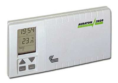
Программируемый цифровой недельный терморегулятор (регулятор температуры) AURATON 2020 (Польша)
СНЯТ С ПРОИЗВОДСТВА. Замена: AURATON 2030.
ОПИСАНИЕ
Программируемый цифровой недельный Терморегулятор AURATON 2020
– Функция отпуска (до 7 дней), а также счетчик времени работы управляемого устройства
– Высокая функциональность, несложное обслуживание и программирование
– Пять уровней температуры – в том числе против замораживания системы
– Диапазон измерения температуры от 0 до 35°C с делением 0,5°C
– Точность установки температуры 0,5°C в диапазоне от 5°C до 27°C
– Рабочая температура от 0 до 50°C
– Два цикла программирования:
1) с понедельника до пятницы – четыре изменения температуры в произвольное время
2) суббота и воскресенье – два изменения температуры в произвольное время
– Фильтр – функция счета времени работы терморегулятора (отопительного оборудования)
– Собственное питание – 2 батареи R6 (АА)
– Многофункциональный дисплей времени, дня, температуры и реализуемой программы
– Предлагаются 2 варианта терморегулятора:
а) с датчиком температуры помещенном на 2,5 м кабеле
б) с датчиком температуры помещенном внутри терморегулятора
ТЕХНИЧЕСКИЕ ХАРАКТЕРИСТИКИ
1. Переменное напряжение: 230В ±10% 50Гц
2. Максимальная сила тока подключаемых приборов: 5,0 А
3. Регулируемая температура: от 5°С до 27°С
4. Точность регулировки: 0,5°С
5. Температура эксплуатации: от 0°С до 50°С
6. Дисплей: Есть
7. Питание: 2 батареи АА
8. Габаритные рамеры: 15,5 см x 8,0 см x 3,5 см
9. Гарантийный срок: 12 месяцев
10. Производитель: AURATON (Польша)
Инструкция, схема подключения (в формате PDF)
Другие терморегуляторы AURATON
ekolain.ru
Комнатный термостат – программатор Auraton 2020 в Гродно (Терморегуляторы)
Электронный термостат-программатор для всех видов отопительного оборудования в доме и офисе. Гарантия – 1 год.
Программатор для отопления Auraton 2020
Особенности
- Экономия энергии до 30% при использовании программатора.
- Высокая функциональность, простое обслуживание и программирование терморегулятора.
- Конкурентоспособная цена – 100% стоимости программатора окупается уже через несколько месяцев эксплуатации
- Два цикла программирования
- с понедельника по пятницу – 4 точки переключения в сутки, которым можно сопоставить 4 различные температуры в произвольное время, в течение суток.
- суббота и воскресенье – по 2 точки переключения температуры в произвольное время, в течение суток, которым можно сопоставить 2 различные температуры.
- Фильтр – функция счета времени работы отопительного оборудования
- Программатор имеет собственное питание – 2 батарейки АА
- Многофункциональный дисплей, на котором отображается время, день недели, температура воздуха и выполняющаяся программа.
- Настройка чувствительности контроля температуры (гистерезиса) от 0,25°C до 1°C
Технические характеристики
Габариты ширина-15,5см x высота-8,0см x длина-3,5см Рабочая температура 0° – 50°C Диапазон измерения температуры 0° – 35°C Диапазон управления температур 5° – 27°C Точность настройки температуры 0,5°C Уровней температуры 4 уровня (рабочие дни), по 2 уровня – вых.дни Антизамораживающая температура Есть Программы 3 (рабочие дни, суббота, воскресенье) Цикл работы 7-дневный Контроль состояния работы Дисплей ЖКИ Максимальный ток нагрузки 5 A при активной нагрузке Питание 2 батареи AA
Скачать Инструкцию Auraton 2020
УСТАНОВКА
Регулятор комнатной температуры должен устанавливаться на внутренней стене в помещении на высоте не ниже 1,5м от пола. Месторасположение регулятора должно быть выбрано так, чтобы исключить воздействие на него сторонних источников тепла и холода, а также сквозняков. Для крепления регулятора необходимо отсоединить заднюю поверхность и закрепить ее на стене, используя предназначенные для этого отверстия.
Комнатный термостат – прибор, который регулирует работу газового котла (нагревательного прибора, кондиционера) в зависимости от температуры воздуха в помещении.
Мы не зря обращаем Ваше внимание на температуру воздуха.
Но начнем по порядку – когда у Вас установлен газовый котел, то температуру в помещении, которою он отапливает, Вы регулируете путем увеличения или уменьшения температуры теплоносителя (ВОДЫ) в Вашей системе отопления. Включение и выключение котла происходит уже в зависимости от того, достигла ли ВОДА в системе отопления заданной на котле температуры. При понижении или повышении температуры за пределами помещения, Вам опять необходимо регулировать температуру отопления на Вашем котле вручную. И эти манипуляции необходимо проделывать весь отопительный сезон, когда температура в отапливаемом помещении становится либо слишком прохладной, либо слишком жаркой.
В таком режиме работы происходят очень частые пуски котла на небольшой период времени. Как правило – один раз в 5-10 минут на 1-2 минуты работы горелки котла. То есть котел постоянно работает в режиме включения-выключения. При этом циркуляционный насос котла работает ПОСТОЯННО, не в зависимости от того горит ли газ в котле или нет.
Расход электроэнергии двухконтурным котлом мощностью 24кВт в отопительный период посчитать не составит труда – это порядка 60-90Вт/час. А это уже 1,44-2,160 кВт в сутки или 43-65 кВт в месяц.
Не о каком комфорте, экономии и долговечности работы газового прибора здесь не может быть и речи.
Как работает комнатный термостат? Вы задаете на термостате необходимую Вам температуру в помещении, – например + 23°С. При понижении температуры воздуха на 0,25°С (порог срабатывания зависимости от моделей термостата), термостат дает команду котлу на включение – котел начинает работать на отопление.
Как только температура воздуха в помещении достигает + 23,25 °С термостат отключает котел. Причем отключает не только горелку, а и насос (начинаем экономить).
Воздух в помещении остывает намного медленнее, чем вода в системе отопления, и частота включений котла сокращается в десятки раз, что не может не сказаться на увеличении срока эксплуатации прибора.
Теперь Вам нет необходимости регулировать температуру на котле вручную – один раз вы ее задали на термостате!
Потеплело зимой на улице – котел не включается, собралась вся семья в доме, температура в помещении повысилась – котел не включается, солнце греет комнату через окно – котел не включается, ваша квартира находиться внутри дома и соседские квартиры Вас подогревают- котел не включается.
Котлы не управляемые термостатом, бесполезно расходуют до 25-30% энергии, так как повышение комнатной температуры, свыше требуемой, даже на 1°С, кроме ощутимого дискомфорта, приводит к значительному перерасходу топлива котлом.
Теперь можете поднять расчетные книжки по газу, посчитать, какую сумму вы заплатили за последний отопительный сезон. Отнять от этой суммы 25-30%– именно на столько бы Вы заплатили меньше за газ, если бы у Вас был установлен комнатный термостат.
Плюс еще 30-40кВт сэкономленной электроэнергии в месяц и еще плюс уменьшение износа котла.
Окупаемость и эффективность прибора очевидна.
Характеристики комнатного термостата – программатора Auraton 2020
- — Производитель: AURATON
- — Страна производитель: Польша
- — Вид терморегулятора: Электронный
- — Тип монтажа терморегулятора: Накладной
- — Область применения терморегулятора: Электрические котлы, Инфракрасные обогреватели, Кондиционирование помещения
- — Дисплей: Да
- — Гарантийный срок: 12 (мес.)
by.bizorg.su
Терморегулятор недельный Auraton-2020, проводной – Терморегуляторы, термостаты – TermArt
Терморегулятор Auraton-2020
Недельный программируемый, соединение с котлом – проводное.
Производитель – Польша.
Особенности:
- Двукратно увеличенная чувствительность котроллера со шкалой на дисплее 0,25°C
- Экономия энергии до 30%
- Высокая функциональность, легкость обслуживания и программирования
- Конкурентоспособная цена – 100% стоимости котроллера окупается уже через несколько месяцев эксплуатации
- Три уровня температуры – дневной, ночной и противоморозный
- Диапазон измерения температуры от 0 до 35°C с делением 0,25°C
- Точность установки температуры 0,25°C в диапазоне от 5°C до 30°C
- Рабочая температура от 0 до 45°C
- Возможность 7-дневного цикла программирования
- Имеет в памяти 9 независимых программ, из которых:
- ПРОГРАММА 0 – устанавливает противоморозную температуру (+7°C) круглосуточно
- ПРОГРАММА 1,2,3 – типичные схемы программирования суток
- ПРОГРАММА 4 – установка суточной дневной температуры
- ПРОГРАММА 5 – установка суточной ночной температуры
- ПРОГРАММА 6,7,8 – позволяет индивидуально устанавливать температуру по собственному усмотрению
- Контроллер имеет автономное питание – 2 батарейки АА
- Многофункциональный дисплей времени, дня, температуры и реализуемой программы
Параметры
| измерения | ширина-15,5cm x высота-8,0cm x длина-3,0cm |
| Диапазон температуры работы | 0° – 45°C |
| Диапазон измерения температуры | 0° – 35°C |
| Диапазон управления температур | 5° – 30°C |
| Точность настройки температуры | 0,25°C |
| Уровни температуры | 2 уровня |
| антизамораживающая температура | + |
| Программы | 9 |
| Цикл работы | 7-дневный |
| Контроль состояния работы | Дисплей LCD |
| Максимальный ток нагрузки | ~5 A |
| Питание | 2 батарейки AA |
Скачать инструкцию к Auraton-2020 (оф.сайт производителя)
termart.com.ua
AURATON 2005 / TX РУКОВОДСТВО ПО ЭКСПЛУАТАЦИИ
AURATON 2005 AURATON 2005 TX RX Plus
0 I AURATON 2005 / AURATON 2005 TX RX PLUS AURATON 2005 AURATON 2005 AURATON 2005 TX RX Plus 18 Вступительные замечания Данная инструкция содержит информацию по регуляторам AURATON 2005 и AURATON 2005
Подробнее
AURATON 2020 AURATON 2020 TX RX Plus
0 I AURATON 2020 / AURATON 2020 TX RX PLUS AURATON 2020 AURATON 2020 AURATON 2020 TX RX Plus 60 Вступительные замечания Данная инструкция содержит информацию по регуляторам AURATON 2020 и AURATON 2020
Подробнее
110 AURATON 3000 AURATON 3000
110 AURATON 3000 AURATON 3000 Поздравляем Вас с покупкой современного регулятора температуры Ауратон 3000 и благодарим за доверие нашей фирме. Новый регулятор будет служить Вам и всей вашей семье годами.
Подробнее
Руковдство по эксплуатации
www.auraton.pl 2021 Руковдство по эксплуатации AURATON 2021 3 Поздравляем Вас с приобретением новейшего терморегулятора, созданного на базе усовершенствованного микропроцессора. AURATON 2021 3 независимые
Подробнее
Руководство по эксплуатации
UTHERM Q3 Цифровой комнатный термостат Руководство по эксплуатации www.computherm.com.ua Страница 1 Общее описание термостата Комнатные термостаты типа UTHERM Q3 могут управлять большей частью предложенными
Подробнее
EUROSTER 2006/2006TX
1 EUROSTER 2006/2006TX 1. Характеристика устройства Две установки температуры: комфортная и экономная Регулятор предназначен для работы в системах отопления и кондиционерных оборудованиях, соответственно
Подробнее
Руководство по эксплуатации
COMPUTHERM Q3 RF Радиоуправляемый цифровой комнатный термостат Руководство по эксплуатации Страница 1 Описание термостата Комнатные термостаты COMPUTHERM Q3 RF могут управлять большей частью предлагаемыми
Подробнее
1. ИНСТРУКЦИЯ ПО УСТАНОВКЕ ПРИБОРА
7 AURATON 30 AURATON 30 Регулятор АУРАТОН 30 был спроектирован так, чтобы Вы самым простым образом могли контролировать температуру в своих домах. Источником питания регулятора температуры служит переменный
Подробнее
-Контроль по температуре пола 21 С,
Инструкция по эксплуатации терморегулятора TH-0507 РАСПОЛОЖЕНИЕ ТЕРМОРЕГУЛЯТОРА ТЕХНИЧЕСКИЕ ХАРАКТЕРИСТИКИ Программируемый терморегулятор имеет возможность работать как на обогрев, так и на охлаждение.
Подробнее
EUROSTER 2006/2006TX
1 EUROSTER 2006/2006TX 1. Характеристика устройства Две установки температуры: комфортная и экономная Регулятор предназначен для работы в системах отопления и кондиционерных оборудованиях, соответственно
Подробнее
Инструкция по эксплуатации
www.auraton.pl 200 Инструкция по эксплуатации AURATON 200 2 ВНИМАНИЕ! A U R AT O N 2 0 0 это беспроводной датчик и контроллер температуры (передатчик), который с целью корректной работы должен быть сопряжён
Подробнее
РУКОВОДСТВО ПО ЭКСПЛУАТАЦИ
MILUX RF РУКОВОДСТВО ПО ЭКСПЛУАТАЦИ RU Комнатный программируемый радитермостат ———————– ОПИСАНИЕ Программируемый электронный радиотермостат MILUX RF предназначен для контроля и регулирования
Подробнее
ТЕРМОСТАТ «EasyConrol F19С»
стр.1 ТЕРМОСТАТ «EasyConrol F19С» Термостат «EasyControl F19C» программируемое устройство, предназначенное для систем электрического подогрева пола или для регулировки/ограничения температуры пола. Термостат
Подробнее
Технические характеристики.
ПЕРЕД ТЕМ, КАК УСТАНАВЛИВАТЬ ЭТО УСТРОЙСТВО, ПРОЧИТАЙТЕ, ПОЖАЛУЙСТА, ИНСТРУКЦИЮ ПО УСТАНОВКЕ Устройство RT300 легко монтируется с помощью монтажной задней панели, которая поставляется вместе с устройством.
Подробнее
CRX_E ПРОГРАММИРУЕМЫЙ ХРОНОТЕРМОСТАТ
CRX_E ПРОГРАММИРУЕМЫЙ ХРОНОТЕРМОСТАТ Спасибо за то, что Вы выбрали нашу продукцию! Этот электронный хронотермостат недельного программирования, прост в обращении и имеет изысканный дизайн. Позволяет максимально
Подробнее
Программируемый термостат
Производственно-коммерческое предприятие КОСТШЕВА Полное товарищество УЛ. СУВАЛЬСКА, 32А 11-500 ГИЖИЦКО ПОЛЬША С учетом изменения норм и оборудования, указанные в тексте параметры и изображения, содержащиеся
Подробнее
NEO ИНСТРУКЦИЯ ПО ИСПОЛЬЗОВАНИЮ
NEO ИНСТРУКЦИЯ ПО ИСПОЛЬЗОВАНИЮ 1 5 2 3 4 6 7 1 День 2 Нужная (установленная) температура 3 Отопление включено / выключено 4 Ночь 5 Функциональная кнопка 6 Снижение температуры днем (5 дней) 7 Снижение
Подробнее
конструкции или теплоносителя;
Назначение и область применения Комнатный электронный хронотермостат VT.АС 709 предназначен для автоматического регулирования и поддержания программно заданной температуры воздуха в помещении, температуры
Подробнее
Oscar W Недельный программатор
Oscar W Недельный программатор Кнопки управления 1 вкл./ выкл. режима отопления 2 автоматический/ ручной режим работы 13 время (часы и минуты) 3 программирование режима отопления 14 отключение режима отопления
Подробнее
Инструкция по монтажу и эксплуатации
TE918WHB-0-RF беспроводной суточный термостат Инструкция по монтажу и эксплуатации Комплект терморегулятора ТЕ918WHB-0-RF состоит из приемника ТЕ2010DE и комнатного термостата ТЕ918WHB. ТЕ918WHB-0-RF обычно
Подробнее
БЕСПРОВОДНЫЙ ПУЛЬТ УПРАВЛЕНИЯ YB1F2
БЕСПРОВОДНЫЙ ПУЛЬТ УПРАВЛЕНИЯ YB1F2 Пульт дистанционного управления Содержание 1. Информация для пользователя ÏÐÅÄÓÏÐÅÆÄÅÍÈÅ! Убедитесь в отсутствии преград между приемником и беспроводным пультом дистанционного
Подробнее
ТЕРМОМЕТРЫ И ТЕРМОСТАТЫ С 1 ДАТЧИКОМ И 1 РЕЛЕ: АКО , АКО 14012, АКО 14031, АКО 14112, АКО 14123, АКО 14602, АКО
ТЕРМОМЕТРЫ И ТЕРМОСТАТЫ С 1 ДАТЧИКОМ И 1 РЕЛЕ: АКО – 14023, АКО 14012, АКО 14031, АКО 14112, АКО 14123, АКО 14602, АКО 14610 СОДЕРЖАНИЕ 1 Описание стр 3 2 Технические данные стр 3 3 Установка стр 3 31
Подробнее
РУКОВОДСТВО ПОЛЬЗОВАТЕЛЯ
РУКОВОДСТВО ПОЛЬЗОВАТЕЛЯ Контроллер солнечных систем Контроллер применяется только для контроля за уровнем заряда аккумуляторов в солнечных фотоэлектрических системах. ТЕХНИЧЕСКИЕ ХАРАКТЕРИСТИКИ 12 В 24
Подробнее
EUROSTER 3000 Comfort
EUROSTER 3000 – РУКОВОДСТВО ПО ОБСЛУЖИВАНИЮ 1 EUROSTER 3000 Comfort ИНСТРУКЦИЯ ПО ОБСЛУЖИВАНИЮ Поздравляем Вас с покупкой современного, программируемого регулятора температуры EUROSTER 3000 Comfort. Благодарим
Подробнее
Wespe Heizung Industrial
2 Оглавление ОГЛАВЛЕНИЕ…3 ОБЩИЕ СВЕДЕНИЯ…4 1. УСТАНОВКА…5 2. УСТАНОВКА…8 3. ПОДКЛЮЧЕНИЕ К СЕТИ…8 4. ИСПОЛЬЗОВАНИЕ…9 5. ОБЗОР ВОЗМОЖНЫХ ДЕФЕКТОВ И НЕИСПРАВНОСТЕЙ…10 6. ИНФОРМАЦИЯ ОБ ИЗДЕЛИИ…11
Подробнее
Инструкция по установке Veria Control T45 VERIA
Инструкция по установке Veria Control T45 VERIA Содержание Введение…3 Описание кнопок и символов на экране…4 Установка и подключение терморегулятора…5 Основные функции – Выбор режима управления теплым
Подробнее
ПАСПОРТ. ИНСТРУКЦИЯ Терморегулятор ТС 401
ПАСПОРТ. ИНСТРУКЦИЯ Терморегулятор ТС 401 TC 401 непрограммируемый терморегулятор, предназначен для управления теплым полом. Этот терморегулятор может быть использован для систем электрического обогрева
Подробнее
1. Приготовить столешницу как указано на рисунке. 2. Поставленную вместе с плитой прокладку надо во время установки плиты наложить вокруг стеклянной рамы на нижней поверхности так, как указано на рисунке.
Подробнее
RTW АВТОНОМНЫЙ ЦИФРОВОЙ ТЕРМОСТАТ
RTW АВТОНОМНЫЙ ЦИФРОВОЙ ТЕРМОСТАТ Уникальная модель: суточное и недельное программирование Питание от 2 батареек типа АА Двухуровневая регулировка температуры в помещении: комфортная и пониженная Управляемое
Подробнее
DELTA i-system. Детектор датчика движения 1,1 Комфорт 5TC1 505, 5TC1 510, 5TC1 514 Детектор датчика движения 2,2 Комфорт 5TC1 506, 5TC1 511, 5TC1 515
s DELTA i-system Детектор датчика движения 1,1 Комфорт 5TC1 505, 5TC1 510, 5TC1 514 Детектор датчика движения 2,2 Комфорт 5TC1 506, 5TC1 511, 5TC1 515 Инструкция по применению и монтажу RU 08.2006 RU Содержание
Подробнее
Электрообогреватель Теплофон Бинар
Электрообогреватель Теплофон Бинар 1. Тип товара: электрообогреватель бытовой с электронной системой управления 2. Характеристики Масса: 12,0 кг Габаритные размеры без ножек: 900x435x105 мм Габаритные
Подробнее
Коммутационный радиомодуль (основной)
Коммутационный радиомодуль (основной) Режимы ОТОПЛЕНИЕ и ОХЛАЖДЕНИЕ с ручным переключением Радиус действия сигнала до 50м в зданиях Недельное программирование 9 заводских и 12 пользовательских программ
Подробнее
Инструкция по эксплуатации
Сплит-системы ERISSON Инструкция по эксплуатации Пульт дистанционного управления В целях безопасной и эффективной эксплуатации необходимо внимательно ознакомиться с данным руководством и сохранить его
Подробнее
docplayer.ru
200 RTH. OFF ON IN OUT ALARM RESET AURATON 200 RTH. Инструкция по эксплуатации AURATON RTH. dla oprogramowania w ver.
Транскрипт
1 200 RTH Инструкция по эксплуатации dla oprogramowania w ver. F03 oraz F0A OFF ON IN OUT ALARM RESET AURATON RTH AURATON 200 RTH
2 2
3 3 Мы рады поздравить Вас с покупкой новейшей модели регулятора температуры, созданного на основе усовершенствованного микропроцессора. AURATON 200 RTH LCD Функция FrostGuard : Защита помещения от замерзания. В о з м о ж н о с т ь ц и к л и ч е с к о г о с н и ж е н и я запрограммированной температуры на 3 C на 6-часовый промежуток времени. LCD-дисплей с подсветкой Дисплей с подсветкой позволяет наблюдать за работой прибора даже в слабо освещённых помещениях. Дополнительные элементы системы AURATON H-1 Оконная ручка (элемент продается дополнительно) Дополнительным элементом системы является оконная ручка, оснащенная передатчиком и датчиками ее положения. Благодаря этому установленная ручка передает информацию о состоянии окна. Ручка различает 4 положения окна: открытое, закрытое, приоткрытое и положение со щелью (микровентиляция). Ручка посылает информацию на приемник RTH, который принимает решение об активации реле, например, для выключения обогревателя в случае открытия окна или понижения температуры на 3 С, если окно приоткрыто, что позволяет экономить энергию. Один приемник RTH обслуживает максимально до 25 ручек. AURATON T-2 AURATON T-2 Термометр (элемент, продаваемый отдельно) Дополнительный элемент системы, позволяющий контролировать температуру в помещении, отличном от того, в котором находится регулятор AURATON 200 RTH.
4 4 Описание регулятора температуры AURATON 200 RTH На передней части корпуса расположен LCD-дисплей с подсветкой, а также функциональные кнопки. AURATON 200 RTH LCD-дисплей кнопка подтверждения или вкл./выкл. регулятора кнопка снижения температуры кнопка повышения температуры кнопки режима временного снижения температуры ź удерживание вкл./выкл. регулятор ( ) ź крраткое нажатие подтверждает установку температуры ( )
5 5 Дисплей Температура В режиме нормальной работы регулятор показывает температуру помещения, в котором он установлен в данный момент. 2. Единица измерения температуры ( ) Температура указана в градусах Цельсия. 3. Индикатор режима временного снижения температуры ( ) Появляется в ходе выполнения программы временного снижения температуры. 4. Индикатор программирования временного снижения температуры ( ) Отображает запланированный пользователем режим временного снижения температуры. Появляется в тот момент, когда режим не выполняется, но функция временного снижения температуры активна (подробнее в разделе Установка режима временного снижения температуры ). 5. Индикатор включения регулятора ( ) Информирует о рабочем состоянии прибора. Появляется в момент включения управляемого оборудования. 6. Символ передачи ( ) Указывает на взаимодействие с приёмником. 7. Разрядка батарей ( ) Индикатор появляется в тот момент, когда исчерпался нижний допустимый уровень напряжения батареек. Необходимо как можно быстрее сменить батарейки. 7
6 6 Описание приемника AURATON RTH Приемник AURATON RTH взаимодействует с беспроводным регулятором AURATON 200 RTH. Приемник устанавливается возле нагревательного или кондиционирующего оборудования и может работать под нагрузкой 16A. отверстия для шурупа, крепящего приемник к стене крепление провода клемма подключения управления (клемма крепления двужильного провода для соединения с нагревательным или кондиционирующим оборудованием) кнопка сопряжения оборудования с приемником RTH крепление провода клемма подключения питания ~ 230 В пер. тока OFF ON IN OUT ALARM RESET AURATON RTH кнопка отмены сопряжения оборудования светодиод, сигнализирующий о работе оборудования обозначения отверстия для шурупа, крепящего приемник к стене ~ 230В пер. тока Обозначения – описание сигналов светодиода Светодиод горит зеленым исполнительное оборудование выключено (короткозамкнутые клеммы COM и NC). Светодиод горит красным исполнительное оборудование включено (короткозамкнутые клеммы COM и NO). Светодиод мигает зеленым приемник RTH ожидает сопряжения с оборудованием – (раздел: Сопряжение беспроводного регулятора AURATON 200 RTH с приемником RTH”). Светодиод мигает красным приемник RTH ожидает отмены сопряжения ранее сопряженного оборудования – (раздел: Отмена сопряжения регулятора с приемником RTH”). Светодиод поочередно мигает красным и зеленым: ALARM – приемник RTH утратил связь с одним из сопряженных устройств – (раздел: “Особые ситуации”) RESET – приемник RTH, отменяет сопряжение со всеми ранее сопряженными единицами оборудования – (раздел: Отмена сопряжения всех устройств, приписанных к приемнику RTH”)
7 7 Выбор соответствующего места для регулятора температуры AURATON 200 RTH Правильность работы регулятора в значительной мере зависит от его месторасположения. Если он будет расположен там, где отсутствует циркуляция воздуха, или под воздействием прямых солнечных лучей, это может привести к неточному контролированию температуры. Регулятор должен быть установлен на внутренней стене дома (простенке), в пространстве со свободной циркуляцией воздуха. Необходимо избегать близости приборов, излучающих тепло (телевизор, калорифер, холодильник), или мест с прямым попаданием солнечных лучей. Сложности могут возникнуть также из-за находящихся рядом дверей, т.к. это может вызывать вибрацию регулятора. Установка / Замена батареек Батарейные отсеки находятся внутри регулятора по обе стороны от дисплея. Чтобы установить батарейки, необходимо снять крышку корпуса регулятора так, как это показано на рисунке. Вставить две батарейки AAA 1,5 V в батарейные отсеки, контролируя правильное расположение полюсов батареек.
8 8 Крепление терморегулятора к стене Чтобы прикрепить регулятор AURATON 200 RTH к стене, необходимо: 1. Снять крышку корпуса регулятора (так, как это изображено в разделе Установка / Замена батарек “). 2. Просверлить в стене два отверстия диаметром 6 мм (расстояние между отверстиями можно определить с помощью задней крышки корпуса терморегулятора). отверстие для крепёжного шурупа отверстие для крепёжного шурупа 3. В просверленные отверстия вставить дюбеля. 4. Прикрутить заднюю крышку корпуса регулятора к стене с помощью входящих в комплект шурупов. 5. Вставить батарейки и приложить верхнюю крышку корпуса регулятора. ВНИМАНИЕ: Если стена деревянная, нет необходимости использовать дюбеля. Достаточно просверлить отверстия диаметром 2,7 мм (вместо 6 мм) и вкрутить шурупы прямо в древесину. Альтернативные варианты монтажа Р е г ул я т о р м о ж н о п р и к р е п и т ь к гл а д к о й п о в е р х н о с т и с помощью, напр., двустороннего скотча. Регулятор можно также установить в каком-либо месте на ровную поверхность с помощью подпорки, находящейся на задней части корпуса.
9 Способ установки приемника RTH 9 Внимание: при установке приемника AURATON RTH подача электроэнергии должна быть отключена. Рекомендуется поручить установку приемника специалисту. 1. Снимите крышку с верхней и нижней части приемникa AURATON RTH. кожух 2. Снимите крышки с верхней и нижней части приемника AURATON RTH. держатель провода OFF ON IN OUT ALARM RESET 3. Нагревательное оборудование подключить к клеммам подключения управления приемника AURATON RTH. Необходимо следовать инструкции по эксплуатации нагревательного оборудования. Наиболее часто используются клеммы COM (общий) и NO (нормально разомкнутая цепь). AURATON RTH 4. Подключите провода питания к клеммам подключения питания приемника AURATON RTH, соблюдая правила техники безопасности. ~230 пер. тока 5. После подключения проводов, их необходимо зафиксировать “держателями провода”, и снова привинтить крышки к приемнику AURATON RTH. ВНИМАНИЕ: В электросети дома должен быть выключатель и максимальная защита тока.
10 10 Крепление приемника RTH к стене Для крепления приемника AURATON RTH к стене следует: 1) Снять крышки с нижней и верхней части регулятора (см. раздел Способ установки приемника RTH”). 2) Отметить на стене положение отверстий для крепежных шурупов. 3) В обозначенных местах просверлить отверстия диаметром, равным диаметру прилагаемых к комплекту дюбелей (5 мм). 4) В просверленные отверстия вставить дюбели. 5) Привинтить приемник RTH шурупами к стене так, чтобы он хорошо держался. отверстие для шурупа, крепящего приемник с стене OFF ON IN OUT ALARM RESET AURATON RTH отверстие для шурупа, крепящего приемник с стене Внимание: Если стена деревянная, нет необходимости в использовании дюбелей. Следует высверлить отверстия диаметром 2,7 мм вместо 5 мм и шурупы ввинтить непосредственно в дерево.
11 11 Сопряжение беспроводного регулятора AURATON 200 RTH с приемником RTH. ВНИМАНИЕ: Беспроводной регулятор AURATON 200 RTH, продава-емый вместе с приемником AURATON RTH, уже является сопряженным. Оборудование, закупаемое отдельно, требует “сопряжения”. OFF ON IN OUT ALARM SET 3. Сопряжение завершилось правильно, если зеленый светодиод перестает мигать на приемнике AURATON RTH и приемник переходит к нормальному режиму работы. В случае возникновения ошибки при сопряжении, следует повторить шаги 1 и 2. В случае если ошибки повторяются, необходимо отменить сопряжение всех устройств с помощью RESET приемника RTH (см RESET – Отмена сопряжения всех устройств, приписанных к приемнику RTH”) и попробовать выполнить сопряжение устройства повторно. ВНИМАНИЕ: LED 1. Сопряжение регулятора 200 RTH с приемником RTH инициируется нажатием левой кнопки сопряжения (зеленый треугольник ) на приемнике RTH и ее удержанием в течение не менее 2 с, до тех пор, пока не начнет мигать зеленый светодиод, после чего мы отпускаем кнопку.. Приемник AURATON RTH ожидает сопряжения в течение 120 секунд. По истечении этого времени он самостоятельно вернется к нормальной работе. 2. На регуляторе AURATON 200 RTH нажимаем кнопку bo ok.. или up ok в течение 6 секунд и удерживаем ее до тех пор, пока на дисплее не загорится символ радиопередачи ( ). К одному приемнику может быть приписан только 1 терморегулятор. Отмена сопряжения регулятора с приемником RTH OFF ON IN OUT LED 1. Отмена сопряжения регулятора 200 RTH с приемником RTH инициируется нажатием правой кнопки отмены сопряжения (красный треугольник ) на приемнике RTH и ее удержанием в течение не менее 2 с, до тех пор, пока не начнет мигать красный светодиод, после чего мы отпускаем кнопку. Приемник AURATON RTH ожидает отмены сопряжения устройства в течение 120 с, после чего он автоматически возвращается в нормальный режим работы.
12 12 2. На регуляторе AURATON 200 RTH нажимаем кнопку bo ok.. или up ok и удерживаем ее в течение 5 секунд до тех пор, пока на дисплее не загорится символ радиопередачи ( ). Отпускаем кнопку. 3. Отмена сопряжения завершилась правильно, если красный светодиод перестает мигать на приемнике AURATON RTH и приемник переходит к нормальному режиму работы. В случае если ошибки будут повторяться, необходимо отменить сопряжение всех сопряженных устройств (см. RESET – Отмена сопряжения всех устройств, приписанных к приемнику RTH”). RESET – Отмена сопряжения всех устройств, приписанных к приемнику RTH LED Для отмены сопряжения всех сопряженных устройств в приемнике RTH необходимо одновременно нажать и удерживать нажатыми обе кнопки сопряжения и отмены сопряжения ( и ) в течение не менее 5 с, до тех пор пока не появится попеременное мигание зеленого и красного светодиода. После этого следует отпустить обе кнопки. OFF ON IN OUT ALARM RESET Если отмена сопряжения всех устройств завершена правильно, то примерно через 2 с цвет лампочки изменится на зеленый, а затем наступят короткие вспышки. ВНИМАНИЕ: Если после нажатия кнопки RESET мы отключим приемник RTH от источника питания, а затем снова подключим питание, то приемник автоматически перейдет в режим “сопряжения” на 120 секунд. Аналогично ведет себя новоприобретенный приемник RTH (не в комплекте с регулятором), не имеющий предварительно сопряженных устройств. Индикация работы и приема пакета данных О каждом приеме радиотрансляции приемником AURATON RTH от сопряженного устройства сигнализирует кратковременное изменение цвета светодиода на оранжевый. После включения реле светодиод имеет красный цвет, после выключения реле светодиод имеет зеленый цвет.
13 13 Первый запуск регулятора AURATON 200 RTH После правильной установки батареек в отсеки, на LCD-дисплее в течение секунды отобразятся все элементы меню (тест дисплея), а затем номер версии программного обеспечения. Через мгновение дисплей автоматически покажет реальную температуру помещения в данный момент. Регулятор готов к работе. Настройка температуры ВНИМАНИЕ: Первое нажатие на любую функциональную кнопку всегда приводит к включению подсветки и лишь затем вызывает функцию данной клавиши. Чтобы в режиме нормальной работы выставить необходимую нам температуру, следует: 1. Нажать на кнопку <pl> или <mi>. Участок экрана, отображающий температуру, перейдёт в режим редактирования и начнёт мигать. 2. Кнопками<lu> и<in> выставляем необходимую нам температуру с точностью до 0,2 C. 3. Выбор подтверждаем коротким нажатием клавиши /wł>. Функция FrostGuard Регулятор AURATON 200 RTH оснащён специальной функцией FrostGuard, защищающей помещение от возможного замерзания. Эта функция активируется, когда регулятор выключен. При выключенном регуляторе, когда температура помещения снизится до 2 C, на дисплее появятся символы Fr ( ) и <p..> iпосле чего будет отправлен сигнал приёмнику, который включит обогрев. Когда температура поднимется до 2,2 C, дисплей снова погаснет и будет отправлен сигнал приёмнику, который отключит обогрев.
14 14 Установка режима временного снижения температуры Е с л и п о к а к и м л и б о п р и ч и н а м в ы ж е л а е т е ежедневно в то же самое время дня снизить температурувашего помещения на 3 C, существует несколько возможностей для её временного снижения на 6 часов. Чтобы это осуществить, следует: 1. Нажать и удерживать в течение 3 секунд обе кнопк <zega>. На дисплее появится символ луны ( ). 2. Регулятор переходит в режим временного снижения температуры и ежед н е в н о в т о же с а м о е в р е м я б уд е т с н и жа т ь запрограммированную в нормальном режиме температуру на 3 C в течение 6 часов. ВНИМАНИЕ: Через 6 часов регулятор вернётся к основному показателю температуры. Вместо символа луны ( ) на экране появится символ солнца ( ). ВНИМАНИЕ: Режим временного снижения температуры всегда начинается в момент включения функции. Это означает, что возможное временное снижение температуры следует запрограммировать в то время суток, когда мы хотим, чтобы такое изменение происходило. takowa zmiana następowała. Отключение режима временного снижения температуры Чтобы отключить режим временного снижения температуры следует снова нажать и удерживать в течение 3 секунд кнопки <zega>. На дисплее погаснет символ луны ( ) или солнца ( ) и будет отображаться только температура помещения. Регулятор вернётся в нормальный режим работы.
15 IN OUT 15 Работа приемника RTH с нагревательным оборудованием Базовая конфигурация устройств Дополнительное оборудование системы OFF ON ALARM RESET AURATON RTH AURATON T-2 AURATON RTH Приемник подключен к нагревательному оборудованию AURATON 200 RTH Беспроводной регулятором температуры AURATON T-2 Беспроводной термометр (покупается отдельно) AURATON H-1 Оконная ручка (покупается отдельно) нагревательное оборудование AURATON RTH Упрощенная схема подключения AURATON RTH к нагревательному оборудованию (беспотенциальный вход) Взаимодействие приемника AURATON RTH с регулятором AURATON 200 RTH и/или термометром AURATON T-2 Действие регулировки температуры в приемнике основано на двухпозиционном алгоритме (включить/выключить), использующем один или два датчика. Регулятор AURATON 200 RTH позволяет настраивать температуру и/или осуществлять текущий контроль температуры. Tермометр AURATON T-2 дает лишь информацию о текущей температуре без возможности ее ручного изменения. A) Ручная настройка сопрягаясь с приемником RTH, регулятор AURATON 200 RTH предоставляет возможность ручной настройки температуры и ее контроля в месте установки регулятора 200 RTH.
16 16 B) Дистанционная настройка если с этим приемником RTH мы дополнительно сопрягаем термометр T-2, то в таком случае регулятор AURATON 200 RTH сохраняет возможность настраивать температуру, однако контролировать ее можно только сопряженным термометром T-2. Это позволяет контролировать температуру в другом помещении, отличном от того, в котором находится регулятор AURATON 200 RTH. Пример: Мы хотим, чтобы в “детской комнате” всегда была температура 22 C, однако не хотим, чтобы дети имели возможность ее изменять. В таком случае мы устанавливаем термометр Т-2 в этой комнате, а регулятор AURATON 2025 RTH, к примеру, в кухне. С помощью этого решения в “детской комнате” всегда будет поддерживаться температура 22 С, независимо от температурных колебаний на кухне. C) Предустановка (20 C) если с приемником RTH сопрягаем только термометр T-2, нельзя будет вручную настраивать температуру, а приемник RTH будет поддерживать предустановленную температуру 20 C. ВНИМАНИЕ! 1. Очень важна очередность сопряжения регулятора AURATON 200 RTH и термометра T-2. Если мы хотим выполнить удаленную настройку, прежде всего, следует с приемником RTH выполнить сопряжение регулятора AURATON 200 RTH, а затем термометра T-2. Отмена сопряжения приведет к автоматической отмене сопряжения с термометром Т-2 и к переходу в режим работы, описанный в п. A. 2. Приемник RTH может работать только с одним регулятором AURATON 200 RTH и/или термометром Т-2. Сопряжение с новым регулятором приведет к отмене сопряжения между ранее сопряженным регулятором и термометром Т-2. Сопряжение нового термометра Т-2 вызовет отмену сопряжения только ранее сопряженного термометра Т Регулятор 200 RTH и/или термометр T-2 может работать с бесконечным количеством приемников, например, один регулятор может управлять одновременно двумя независимыми нагревательными устройствами.
17 17 Взаимодействие с регулятором AURATON 200 RTH и/или термометром AURATON T-2, а также ручками AURATON H-1 По умолчанию приемник AURATON RTH не имеет сопряжения ни с одной ручкой AURATON H-1, то есть реле по умолчанию управляется сопряженным регулятором AURATON 200 RTH и/или термометром AURATON T-2. В момент, когда мы установим с приемником RTH сопряжение хотя бы одной ручки H-1, то управление работой реле будет выполняться следующим образом: A) Окно закрыто или неплотно прикрыто (микровентиляция). Когда будет установлено сопряжение между приемником и ручками H-1 и все окна будут закрыты или неплотно закрыты, реле продолжает выполнять команды с сопряженного регулятора AURATON 200 RTH и/или термометра T-2. B) Окно приоткрыто. Когда мы приоткроем хотя бы одно окно, в приемнике AURATON RTH произойдет падение установленной температуры регулятора AURATON 200 RTH на 3 C. Это состояние будет продолжаться до тех пор, пока не будут закрыты или неплотно закрыты все приписанные к приемнику RTH окна. Пример: На регуляторе AURATON 2025 RTH установлена температура 21 C. Затем мы приоткрываем окно с сопряженной ручкой H-1. Приемник RTH будет поддерживать в помещении температуру 18 C. C) Oкно открыто. Когда открывается окно с сопряженной ручкой H-1 на время более 30 с, реле приемника AURATON RTH будет выключено и нагревательное устройство также выключиться. Если все приписанные окна снова будут иметь состояние, отличное от открытого, приемник RTH возвратится к нормальному взаимодействию с регулятором AURATON 200 RTH и/или термометром T-2, в течение периода времени не короче 90 с с момента выключения реле. Такая задержка предусмотрена для того, чтобы предотвратить слишком быстрые переходы нагревательных приборов между состояниями включеновыключено. Однако если температура в помещении опустится ниже 7 С, независимо от положения окон, реле приемника включается, включая тем самым нагревательное оборудование для предотвращения замерзания помещения. D) Потеря сигнала. Когда приемник RTH потеряет сигнал с сопряженной ручки H-1 (потеря 3 следующих подряд радиотрансляций), он изменяет статус этого окна на закрытое. После восстановления связи, данные от ручки Н-1 снова правильно читаются приемником RTH.
18 18 Особые ситуации ź В случае, когда теряются 3 следующие друг за другом радиотрансляции (через 15 минут) с регулятора AURATON 200 RTH и/или термометра T-2, поступит аварийный сигнал на приемник RTH (попеременное мигание красного и зеленого светодиода). До устранения проблемы приемник RTH перейдет к выполнению цикла включений/выключений последних 24 часов, содержащийся в памяти. ź Когда оба сигнала восстановятся (с регулятора AURATON 200 RTH и термометра T-2), ошибка будет аннулирована и приемник перейдет в нормальный режим работы. ź ź ź Если восстановится только сигнал термометра T-2, приемник использует последнюю сохраненную настройку и поддерживает ее, продолжая сигнализировать об аварии. Если с приемником сопряжены ручки H-1, термометр T-2 и регулятор AURATON 200 RTH (температура измеряется термометром T-2), то поддержание цикла работы последних 24 часов произойдет только после потери сигнала с термометра T-2. Когда отсутствует только сигнал регулятора AURATON 200 RTH, то приемник RTH автоматически поддерживает последнюю сохраненную настройку регулятора AURATON 200 RTH, и также сигнализирует об аварии. Когда с приемником RTH сопряжены только ручки Н-1, и сопряжен также один термометр Т-2 без регулятора AURATON 200 RTH, приемник RTH будет поддерживать постоянную предустановленную температуру 20 C. Если мы приоткроем какое-нибудь окно с сопряженной ручкой H-1, будет поддерживаться температура 17 C. Если мы откроем какоенибудь окно с сопряженной ручкой H-1, приемник RTH выключит нагревательное оборудование и снова включит его, если температура упадет ниже 7 C.
19 19 Уникальные свойства AURATON 200 RTH ź Переключение реле синхронизировано с электрической сетью 230 В таким образом, что замыкание и размыкание контактов якоря реле происходило всегда вблизи перехода напряжения сети через нуль. Это предотвращает искрение и значительно увеличивает срок службы реле. ź Приемник AURATON RTH оснащен уникальным алгоритмом анализа циклов включить-выключить. Весь цикл нагрева за последние 24 часа хранится в памяти приемника RTH. В случае потери связи с регулятором AURATON 200 RTH и/или термометром T-2, приемник RTH будет автоматически выполнять сохраненный цикл включений/выключений за последние 24 ч. Это предоставляет время для восстановления связи (устранения помех), или ремонта регулятора 200 RTH и/или термометра T-2 без значительного ухудшения теплового комфорта на объекте управления. Дополнительная информация и замечания ź Регулятор AURATON 200 RTH или/и термометр T-2 должны быть установлены на расстоянии не менее 1 метра от приемника RTH (слишком сильный сигнал передатчиков может вызвать сбои). ź Между очередным выключением и включением реле должен быть интервал мин. 30 с. ź Радиопередача данных с регулятора AURATON 200 RTH на приемник происходит при каждом изменении температуры окружения на 0,2 C. В случае, когда температура не изменяется, регулятор отправляет контрольные данные каждые 5 минут (об этом свидетельствует мигание оранжевого светодиода на приемнике RTH). ź При отключении питания приемник RTH выключается. При восстановлении питания нагревательное оборудование автоматически включается, а приемник RTH будет ожидать ближайшего сигнала с сопряженных передатчиков (этот сигнал должен поступить не позднее чем в течение 5 минут после восстановления питания). После получения сигнала приемник RTH перейдет в режим нормальной работы. ź Не размещайте приемник RTH в металлических корпусах (например, в монтажных шкафах, металлических корпусах печи), чтобы не нарушить работу регулятора. ź Регулятор можно включать и выключать в любой момент путём короткого удерживания кнопки <w>. ź Первое нажатие на любую функциональную кнопку всегда приводит к включению подсветки, и только затем происходит вызов функции клавиши. ź При программировании какой бы то ни было функции не нажатие ни на одну кнопку в течение 10 секунд равнозначно нажатию на кнопку <O.>.
20 20 Схема подключения приемника AURATON RTH ~230В L N нагревательное оборудование например: газовый или электрический котел с беспотенциальным входом. OFF ON IN OUT ALARM RESET AURATON RTH AURATON 200 RTH L N ~230 пер. тока Макс. 230В ~ N L электр. нагрев. приборы Макс. 230В ~ 8 A OFF ON IN OUT ALARM RESET AURATON RTH AURATON 200 RTH L N ~230 пер. тока
21 21 Технические характеристики Рабочая температура: Диапазон измерения температуры: 0 45 C 0 35 C Диапазон управления температурой: 5 30 C Гистерезис: ±0,2 C Точность выставления температуры: 0,2 C Точность показаний температуры: ±0,2 C Температура, установленная по умолчанию: 20 C Дополнительная функция: FrostGuard Цикл работы: суточный Контроль состояния работы: светодиоды (приемник RTH) ЖК-дисплей (регулятор) Максимальный ток нагрузки контактов реле: AURATON RTH ~16A 250В пер.тока Питание AURATON 200 RTH 2x алкалиновая AAA 1,5V Питание RTH: 230VAC, 50Hz Радиочастота: RTH: 868MHz Дальность связи RTH: в стандартном доме, со стандар- тной конструкцией стен около 30 м, на открытом пространстве до 300 м Утилизация прибора Изделие обозначено знаком перечёркнутого мусорного контейнера. В соответствии с европейской директивой 2002/96/ЕС и законом об использованном электрическом и электронном оборудовании такая маркировка информирует о том, что данное изделие по истечении срока его службы не может быть утилизировано вместе с другими отходами домашнего хозяйства. Пользователь обязан сдать его в пункт сбора использованного электрического и электронного оборудования.
22 22 Шаблон для сверления отверстий для приемника AURATON RTH в масштабе 1:1
23 23
24
docplayer.ru
Auraton 2020 инструкция- AURATON 2020 : .(термостат) AURATON 2020,инструкция . – Блоги
|
Auraton 2020 инструкция
служебная записка о лишении премии образец
genius программа для поиска драйверов |
aeterna.qip.ru
Auraton 2020 инструкция- AURATON 2020 : .(термостат) AURATON 2020,инструкция . – Блоги
|
Auraton 2020 инструкция

скачать драйвер wdbaar5000abk
детский электромотоцикл инструкция |
aeterna.qip.ru