
Руководства пользователя
Версия E10276
91.95 KB
HDMI insert (English)
Версия G8155
1.67 MB
SABERTOOTH Z87 user’s manual(German)
Версия F7868
15.33 MB
SABERTOOTH Z87 user’s manual(French)
Версия S7868
9.36 MB
SABERTOOTH Z87 User’s Manual (Spanish)
Версия —
2.09 MB
LGA1150 CPU installation Manual
Версия T7868
12.43 MB
SABERTOOTH Z87 User’s Manual(Traditional Chinese)
Версия J7868
8.2 MB
SABERTOOTH Z87 User’s Manual (Japanese)
Версия G7868
9.35 MB
SABERTOOTH Z87 user’s manual(German)
Версия E7868
13.1 MB
SABERTOOTH Z87 User’s Manual (English)
Версия C7868
12.47 MB
SABERTOOTH Z87 User’s Manual (Simplified Chinese)
-
Драйверы
38
-
Инструкции по эксплуатации
2
Языки:

ASUS SABERTOOTH Z87 инструкция по эксплуатации
(164 страницы)
- Языки:Японский
-
Тип:
PDF -
Размер:
8.2 MB -
Описание:
SABERTOOTH Z87 User’s Manual (Japanese)
SABERTOOTH Z87 User’s Manual (Japanese)
Просмотр

ASUS SABERTOOTH Z87 инструкция по эксплуатации
(166 страниц)
- Языки:Испанский
-
Тип:
PDF -
Размер:
9.36 MB -
Описание:
SABERTOOTH Z87 User’s Manual (Spanish)
SABERTOOTH Z87 User’s Manual (Spanish)
Просмотр
На NoDevice можно скачать инструкцию по эксплуатации для ASUS SABERTOOTH Z87. Руководство пользователя необходимо для ознакомления с правилами установки и эксплуатации ASUS SABERTOOTH Z87. Инструкции по использованию помогут правильно настроить ASUS SABERTOOTH Z87, исправить ошибки и выявить неполадки.
Справочник Пользователя (English)Справочник Пользователя (中文(zhōngwén))Справочник Пользователя (Français)Справочник Пользователя (Deutsch)Справочник Пользователя (English)Справочник Пользователя (日本語 (にほんご))Справочник Пользователя (Español)Справочник Пользователя (中文(zhōngwén))Справочник ПользователяСправочник Пользователя (Deutsch)
-
Asus SABERTOOTH Z87 — page 1
Motherboard SABERTOOTH Z87 …
-
Asus SABERTOOTH Z87 — page 2
ii First Edition April 2013 Copyright © 2013 ASUST eK COMPUTER INC. All Rights Reserved. No part of this manual, including the products and software described in it, may be reproduced, transmitted, transcribed, stored in a retrieval system, or translated into any language in any form or by any means, except documentation kept by the purchaser for …
-
Asus SABERTOOTH Z87 — page 3
iii Contents Safety information ………………………………………………………………………………………… vi About this guide ………………………………………………………………………………………….. vii SABERTOOTH Z87 specications summary ……………………………………….. …
-
Asus SABERTOOTH Z87 — page 4
iv 2.3 Motherboard rear and audio connections ……………………………………… 2-12 2.3.1 Rear I/O connection ………………………………………………………… 2-12 2.3.2 Audio I/O connections ……………………………………………………… 2-14 2.4 Starting up for the rst time …………………. …
-
Asus SABERTOOTH Z87 — page 5
v 4.2.1 Running the support DVD ………………………………………………….. 4-1 4.2.2 Obtaining the software manuals ………………………………………….. 4-3 4.3 Software information ……………………………………………………………………… 4-4 4.3.1 AI Suite 3 ……………………………. …
-
Asus SABERTOOTH Z87 — page 6
vi Safety information Electrical safety T o prevent electrical shock hazard, disconnect the power cable from the electrical outlet before relocating the system. When adding or removing devices to or from the system, ensure that the power cables for the devices are unplugged before the signal cables are connected. If possible, disconnect all power c …
-
Asus SABERTOOTH Z87 — page 7
vii About this guide This user guide contains the information you need when installing and conguring the motherboard. How this guide is organized This guide contains the following parts: • Chapter 1: Product introduction This chapter describes the features of the motherboard and the new technology it supports. It includes description of the sw …
-
Asus SABERTOOTH Z87 — page 8
viii Conventions used in this guide T o ensure that you perform certain tasks properly , take note of the following symbols used throughout this manual. DANGER/W ARNING: Information to prevent injury to yourself when trying to complete a task. CAUTION: Information to prevent damage to the components when trying to complete a task IMPORT ANT : Instr …
-
Asus SABERTOOTH Z87 — page 9
ix SABERTOOTH Z87 specications summary CPU LGA1 150 socket for the 4th Generation Intel ® Core™ i7/Intel ® Core™i5/Intel ® Core™ i3, Pentium ® and Celeron ® processors Supports 22nm CPU Supports Intel ® T urbo Boost T echnology 2.0* * The Intel ® T urbo Boost T echnology 2.0 support depends on the CPU types. Chipset Intel ® Z87 Exp …
-
Asus SABERTOOTH Z87 — page 10
x Storage Intel ® Z87 Express Chipset — 6 x SA T A 6.0 Gb/s ports (brown) with RAID 0, 1, 5 and 10 support — Supports Intel ® Smart Response T echnology , Intel ® Rapid Start T echnology , Intel ® Smart Connect T echnology* 2 x ASMedia ® SA T A 6Gb/s controllers** — 2 x SA T A 6.0 Gb/s ports (beige) — 2 x eSA T A 6.0 Gb/s ports (red) * These f …
-
Asus SABERTOOTH Z87 — page 11
xi (continued on the next page) SABERTOOTH Z87 specications summary Other Special Features — USB 3.0 Boost featuring speedy USB 3.0 transmission — USB BIOS Flashback — USB Charger+ — Network iControl — ASUS UEFI BIOS EZ Mode featuring friendly graphics user interface — AI Suite 3 — Remote GO! — ASUS Q-Connector — ASUS Q-Shield — ASUS Q-LED (CPU, …
-
Asus SABERTOOTH Z87 — page 12
xii Internal I/O connectors 1 x Clear CMOS jumper Front panel audio connector (AAFP) System panel (Q-Connector) 24-pin EA TX Power connector 8-pin EA TX 12V Power connector BIOS features 64 Mb Flash ROM, UEFI AMI BIOS, PnP , DMI 2.7, WfM 2.0, SM BIOS 2.7, ACPI 5.0, Multi-language BIOS, ASUS EZ Flash 2, ASUS CrashFree BIOS 3, My Favorites, Quick Not …
-
Asus SABERTOOTH Z87 — page 13
xiii User Manual ASUS SABERTOOTH Z87 motherboard T echnical documentations, certication and warranty card Support DVD 4 x Serial A T A 6.0 Gb/s cables 1 x ASUS SLI™ bridge connector 1 x ASUS Q-Shield 1 x 2-in-1 ASUS Q-Connector kit 2 x 35mm Assistant fans 2 x short fan screws 4 x long fan screws 3 x PCIe x16 slot covers 3 x PCIe x1 slot covers …
-
Asus SABERTOOTH Z87 — page 14
xiv Installation tools and components 1 bag of screws Philips (cross) screwdriver PC chassis Power supply unit Intel ® LGA1 150 CPU Intel ® LGA1 150 compatible CPU Fan DIMM SA T A hard disk drive SA T A optical disc drive (optional) Graphics card (optional) The tools and components in the table above are not included in the motherboard package. …
-
Asus SABERTOOTH Z87 — page 15
ASUS SABERT OOTH Z87 1-1 Chapter 1 Product introduction 1 1.1 Special features 1.1.1 Product highlights LGA1 150 socket for 4th generation Intel ® Core™ i7/Intel ® Core™ i5/Intel ® Core™ i3, Pentium ® and Celeron ® processors This motherboard supports 4th generation Intel ® Core™ i7/Intel ® Core™ i5/Intel ® Core™ i3, Pentium ® …
-
Asus SABERTOOTH Z87 — page 16
1-2 Chapter 1: Product introduction Chapter 1 Intel ® Smart Response T echnology Intel ® Smart Response T echnology , an important part of Green ASUS eco-friendly computing, reduces load and wait time, eliminates unecessary hard drive spin thus lowering power usage, and uses an installed SSD (requires 18.6 GB available space) as a cache for frequ …
-
Asus SABERTOOTH Z87 — page 17
ASUS SABERT OOTH Z87 1-3 Chapter 1 1.1.3 “TUF Engine” Power Design Digital Power Control ASUS DIGI+ Power Control features the revolutionary and innovative digital VRM, DRAM, and CPU V oltage controllers. These controllers offers ultra-precise memory and voltage tuning for optimal system efciency , stability and performance. TUF Components ( …
-
Asus SABERTOOTH Z87 — page 18
1-4 Chapter 1: Product introduction Chapter 1 1.1.5 ASUS EZ DIY ASUS UEFI BIOS (EZ Mode) ASUS UEFI BIOS, a UEFI compliant architecture, offers the rst mouse-controlled intuitive graphical BIOS interface that goes beyond the traditional keyboard-only BIOS controls, providing you with more exibility , convenience, and easy to navigate UEFI BIOS …
-
Asus SABERTOOTH Z87 — page 19
ASUS SABERT OOTH Z87 1-5 Chapter 1 1.1.6 ASUS Exclusive Features Remote GO! ASUS Remote GO! leads the way to a more enjoyable home entertainment. With ASUS Remote GO!, you can wirelessly stream media les to DLNA devices, remotely control and access your computer using your smart device and easily transfer les between your computer and smart d …
-
Asus SABERTOOTH Z87 — page 20
1-6 Chapter 1: Product introduction Chapter 1 1.1.7 Other special features DisplayPort Support DisplayPort is a digital display interface standard that delivers up to 10.8 Gbps of bandwidth over standard cables, providing billions of colors and bi-directional communications, thus enabling the fastest refresh rates, and the highest resolution digita …
-
Asus SABERTOOTH Z87 — page 21
ASUS SABERT OOTH Z87 1-7 Chapter 1 • Unplug the power cord from the wall socket before touching any component. • Before handling components, use a grounded wrist strap or touch a safely grounded object or a metal object, such as the power supply case, to avoid damaging them due to static electricity . • Hold components by the edges to avoid t …
-
Asus SABERTOOTH Z87 — page 22
1-8 Chapter 1: Product introduction Chapter 1 Refer to 1.2.9 Internal connectors and 2.3.1 Rear I/O connection for more information about rear panel connectors and internal connectors. 1.2.2 Motherboard layout …
-
Asus SABERTOOTH Z87 — page 23
ASUS SABERT OOTH Z87 1-9 Chapter 1 Layout contents Connectors/Jumpers/Slots Page 1. A TX power connectors (24-pin EA TXPWR, 8-pin EA TX12V) 1-32 2. CPU, optional, chassis, and assistant fan connectors (4-pin CPU_F AN, 4-pin CPU_OPT , 4-pin CHA_F AN1-4, 3-pin ASST_F AN1-2 ) 1-30 3. LGA1 150 CPU socket 1-10 4. DDR3 DIMM slots 1-1 1 5. MemOK! button 1 …
-
Asus SABERTOOTH Z87 — page 24
1-10 Chapter 1: Product introduction Chapter 1 1.2.3 Central Processing Unit (CPU) The motherboard comes with a surface mount LGA1 150 socket designed for the 4th Generation Intel ® Core™ i7 / Intel ® Core™ i5 / Intel ® Core™ i3, Pentium ® and Celeron ® processors. • Ensure that all power cables are unplugged before installing the CPU. …
-
Asus SABERTOOTH Z87 — page 25
ASUS SABERT OOTH Z87 1-1 1 Chapter 1 Recommended memory congurations 1.2.4 System memory The motherboard comes with four Double Data Rate 3 (DDR3) Dual Inline Memory Modules (DIMM) slots. A DDR3 module is notched differently from a DDR or DDR2 module. DO NOT install a DDR or DDR2 memory module to the DDR3 slot. …
-
Asus SABERTOOTH Z87 — page 26
1-12 Chapter 1: Product introduction Chapter 1 • Y ou may install varying memory sizes in Channel A and Channel B. The system maps the total size of the lower-sized channel for the dual-channel conguration. Any excess memory from the higher-sized channel is then mapped for single-channel operation. • According to Intel ® CPU spec, DIMM volt …
-
Asus SABERTOOTH Z87 — page 27
ASUS SABERT OOTH Z87 1-13 Chapter 1 SABERTOOTH Z87 Motherboard Qualied V endors Lists (QVL) DDR3 2666 MHz capability V endors Part No. Size SS/DS Chip Brand Chip NO. Timing V oltage DIMM socket support (Optional) 2 4 G.SKILL F3-2666CL10Q-16GBZHD(XMP) 16GB (4x4GB) DS — — 9-1 1-9-27 1.65 • • GEIL GOC332GB2666C1 1QC(XMP) 32GB (4x8GB) DS — — 9-9 …
-
Asus SABERTOOTH Z87 — page 28
1-14 Chapter 1: Product introduction Chapter 1 DDR3 2200 MHz capability V endors Part No. Size SS/DS Chip Brand Chip NO. Timing Voltage DIMM socket support (Optional) 2 4 G.SKILL F3-17600CL7D-4GBFLS(XMP) 4G (2x2GB) DS — — 7-10-10-28 1.65 • • GEIL GET34GB2200C9DC(XMP) 4GB (2x2GB) DS — — 9-10-9-28 1.65 • • GEIL GET38GB2200C9ADC(XMP) 8GB (2x4G …
-
Asus SABERTOOTH Z87 — page 29
ASUS SABERT OOTH Z87 1-15 Chapter 1 DDR3 1866 MHz capability V endors Part No. Size SS/ DS Chip Brand Chip NO. Timing V oltage DIMM socket support (Optional) 2 4 CORSAIR CMD16GX3M2A1866C9 (V er5.29)(XMP) 16GB (2x8GB) DS — — 1866 9-9-9-27 1.5 • CORSAIR CMD16GX3M4A1866C9 (V er4.13)(XMP) 16GB (4x4GB) DS — — 9-10-9-27 1.5 • • CORSAIR CMD16GX3M4A1 …
-
Asus SABERTOOTH Z87 — page 30
1-16 Chapter 1: Product introduction Chapter 1 DDR3 1600 MHz capability (continued on the next page) V endors Part No. Size SS/ DS Chip Brand Chip NO. Timing Voltage DIMM socket support (Optional) 2 4 Asint SLA302G08-EGJ1C(XMP) 4GB DS Asint 302G08-GJ1C 9-9-9-27 — • • Asint SLA302G08-EGN1C 4GB DS ASint 302G08-GN1C — — • • Asint SLB304G08-EGN …
-
Asus SABERTOOTH Z87 — page 31
ASUS SABERT OOTH Z87 1-17 Chapter 1 V endors Part No. Size SS/ DS Chip Brand Chip NO. Timing V oltage DIMM socket support (Optional) 2 4 KINGSTON KVR16N1 1/4 4G DS Hynix H5TQ2G8 3CFRPBC — 1.5 • • KINGTIGER KTG2G1600PG3(XMP) 2GB DS — — — — • • MICRON MT16JTF1G64AZ-1G6D1 8GB DS MICRON D9PBC — 1.5 • • MICRON MT16KTF51264AZ-1G6M1 4GB DS MIC …
-
Asus SABERTOOTH Z87 — page 32
1-18 Chapter 1: Product introduction Chapter 1 DDR3 1333 MHz capability V endors Part No. Size SS/DS Chip Brand Chip NO. Timing Voltage DIMM socket support (Optional) 2 4 EK Memory EKM324L28BP8-I13 4GB (2x2GB) DS — — 9 — • • G.SKILL F3-10600CL9D-4GBNT 4GB (2x2GB) DS G.SKILL D3 128M8CE9 2GB 9-9-9-24 1.5 • • G.SKILL F3-10666CL9D-8GBRL 8GB (2x …
-
Asus SABERTOOTH Z87 — page 33
ASUS SABERT OOTH Z87 1-19 Chapter 1 Side(s): SS — Single-sided DS — Double-sided DIMM support: (1) Supports one (1) module inserted into any slot as Single-channel memory conguration. We suggest that you install the module into A2 slot. (2) Supports two (2) modules inserted into either the dark brown slots or the beige slots as one pair of Dual- …
-
Asus SABERTOOTH Z87 — page 34
1-20 Chapter 1: Product introduction Chapter 1 1.2.5 Expansion slots Unplug the power cord before adding or removing expansion cards. Failure to do so may cause you physical injury and damage motherboard components. Slot No. Slot Description 1 PCIe 2.0 x1_1 slot 2 PCIe 3.0/2.0 x16_1 slot 3 PCIe 2.0 x1_2 slot 4 PCIe 3.0/2.0 x16_2 slot 5 PCIe 2.0 x1_ …
-
Asus SABERTOOTH Z87 — page 35
ASUS SABERT OOTH Z87 1-21 Chapter 1 • We recommend that you provide sufcient power when running CrossFireX™ or SLI™ mode. • Connect a chassis fan to the motherboard connector labeled CHA_F AN1-4 when using multiple graphics cards for better thermal environment. IRQ assignments for this motherboard PCIe x16_3 Conguration PCI Express sh …
-
Asus SABERTOOTH Z87 — page 36
1-22 Chapter 1: Product introduction Chapter 1 1.2.6 Onboard buttons Onboard buttons allow you to ne-tune performance when working on a bare or open- case system. This is ideal for overclockers and gamers who continually change settings to enhance system performance. 1. MemOK! button Installing DIMMs that are not compatible with the motherboard …
-
Asus SABERTOOTH Z87 — page 37
ASUS SABERT OOTH Z87 1-23 Chapter 1 Ensure to save your data before using the DirectKey button. 2. DirectKey button This feature allows your system to go to the BIOS Setup program with the press of a button. With DirectKey , you can enter the BIOS anytime without having to press the <Delete> key during POST . It also allows you to turn on or …
-
Asus SABERTOOTH Z87 — page 38
1-24 Chapter 1: Product introduction Chapter 1 1.2.7 Jumpers 1. Clear RTC RAM (3-pin CLRTC) This jumper allows you to clear the Real T ime Clock (RTC) RAM in CMOS. Y ou can clear the CMOS memory of date, time, and system setup parameters by erasing the CMOS RTC RAM data. The onboard button cell battery powers the RAM data in CMOS, which include sys …
-
Asus SABERTOOTH Z87 — page 39
ASUS SABERT OOTH Z87 1-25 Chapter 1 1.2.8 Onboard LEDs 1. POST State LEDs The POST State LEDs provide the status of these key components during POST (Power-On-Self T est): CPU, memory modules, VGA card, and hard disk drive.s If an error is found, the critical component’s LED stays lit up until the problem is solved. 2. Standby Power LED The mothe …
-
Asus SABERTOOTH Z87 — page 40
1-26 Chapter 1: Product introduction Chapter 1 1.2.9 Internal connectors 1. Intel ® Z87 Serial A T A 6.0 Gb/s connectors (7-pin SA T A6G_1-6 [brown]) These connectors connect to Serial A T A 6.0 Gb/s hard disk drives via Serial A T A 6.0 Gb/s signal cables. If you installed Serial A T A hard disk drives, you can create a RAID 0, 1, 5, and 10 con? …
-
Asus SABERTOOTH Z87 — page 41
ASUS SABERT OOTH Z87 1-27 Chapter 1 2. ASMedia ® Serial A T A 6.0 Gb/s connectors (7-pin SA T A6G_E12 [beige]) These connectors connect to Serial A T A 6.0 Gb/s hard disk drives via Serial A T A 6.0 Gb/s signal cables. • ASMedia storage controller can only support AHCI mode. • These SA T A ports are for data drives only . 3. USB 3.0 connector …
-
Asus SABERTOOTH Z87 — page 42
1-28 Chapter 1: Product introduction Chapter 1 4. Digital audio connector (4-1 pin SPDIF_OUT) This connector is for an additional Sony/Philips Digital Interface (S/PDIF) port. Connect the S/PDIF Out module cable to this connector , then install the module to a slot opening at the back of the system chassis. The S/PDIF module is purchased separately …
-
Asus SABERTOOTH Z87 — page 43
ASUS SABERT OOTH Z87 1-29 Chapter 1 DO NOT connect a 1394 cable to the USB connectors. Doing so will damage the motherboard! Y ou can connect the front panel USB cable to the ASUS Q-Connector (USB, dark brown) rst, and then install the Q-Connector (USB) to the USB connector onboard if your chassis supports front panel USB ports. The USB 2.0 modu …
-
Asus SABERTOOTH Z87 — page 44
1-30 Chapter 1: Product introduction Chapter 1 6. CPU, optional, chassis, and assistant fan connectors (4-pin CPU_F AN; 4-pin CPU_OPT ; 4-pin CHA_F AN1-4; 3-pin ASST_F AN1-2) Connect the fan cables to the fan connectors on the motherboard, ensuring that the black wire of each cable matches the ground pin of the connector . • DO NOT forget to conn …
-
Asus SABERTOOTH Z87 — page 45
ASUS SABERT OOTH Z87 1-31 Chapter 1 7. Front panel audio connector (10-1 pin AAFP) This connector is for a chassis-mounted front panel audio I/O module that supports either HD Audio or legacy AC`97 audio standard. Connect one end of the front panel audio I/O module cable to this connector . • We recommend that you connect a high-denition front …
-
Asus SABERTOOTH Z87 — page 46
1-32 Chapter 1: Product introduction Chapter 1 • For a fully congured system, we recommend that you use a power supply unit (PSU) that complies with A TX 12 V Specication 2.0 (or later version) and provides a minimum power of 350 W . • DO NOT forget to connect the 4-pin/8-pin EA TX12 V power plug. Otherwise, the system will not boot. • …
-
Asus SABERTOOTH Z87 — page 47
ASUS SABERT OOTH Z87 1-33 Chapter 1 • System power LED (2-pin PLED) This 2-pin connector is for the system power LED. Connect the chassis power LED cable to this connector . The system power LED lights up when you turn on the system power , and blinks when the system is in sleep mode. • Hard disk drive activity LED (2-pin IDE_LED) This 2-pin co …
-
Asus SABERTOOTH Z87 — page 48
1-34 Chapter 1: Product introduction Chapter 1 1 1. TPM connector (20-1 pin TPM) This connector supports a T rusted Platform Module (TPM) system, which securely store keys, digital certicates, passwords and data. A TPM system also helps enhance the network security , protects digital identities, and ensures platform integrity . 12. DirectKey con …
-
Asus SABERTOOTH Z87 — page 49
ASUS SABERT OOTH Z87 2-1 Chapter 2 Basic installation 2 2.1 Building your PC system 2.1.1 Motherboard installation The diagrams in this section are for reference only . The motherboard layout may vary with models, but the installation steps are the same for all models. 1. Install the ASUS Q-Shield to the chassis rear I/O panel. Chapter 2: Basic ins …
-
Asus SABERTOOTH Z87 — page 50
2-2 Chapter 2: Basic installation Chapter 2 3. Place nine screws into the holes indicated by circles to secure the motherboard to the chassis. DO NOT overtighten the screws! Doing so can damage the motherboard. …
-
Asus SABERTOOTH Z87 — page 51
ASUS SABERT OOTH Z87 2-3 Chapter 2 2.1.2 CPU installation Ensure that you install the correct CPU designed for LGA1 150 socket only . DO NOT install a CPU designed for LGA155 and LGA1 156 socket on the LGA1 150 socket. …
-
Asus SABERTOOTH Z87 — page 52
2-4 Chapter 2: Basic installation Chapter 2 2.1.3 CPU heatsink and fan assembly installation Apply the Thermal Interface Material to the CPU heatsink and CPU before you install the heatsink and fan, if necessary . T o install the CPU heatsink and fan assembly …
-
Asus SABERTOOTH Z87 — page 53
ASUS SABERT OOTH Z87 2-5 Chapter 2 T o uninstall the CPU heatsink and fan assembly …
-
Asus SABERTOOTH Z87 — page 54
2-6 Chapter 2: Basic installation Chapter 2 T o remove a DIMM 2.1.4 DIMM installation …
-
Asus SABERTOOTH Z87 — page 55
ASUS SABERT OOTH Z87 2-7 Chapter 2 2.1.5 A TX Power connection OR OR …
-
Asus SABERTOOTH Z87 — page 56
2-8 Chapter 2: Basic installation Chapter 2 2.1.6 SA T A device connection OR OR …
-
Asus SABERTOOTH Z87 — page 57
ASUS SABERT OOTH Z87 2-9 Chapter 2 2.1.7 Front I/O Connector T o install ASUS Q-Connector IDE LED POWER SW RESET SW HDD LED- HDD LED+ PWR Reset Ground Ground USB 2.0 AAFP T o install USB 2.0 connector T o install front panel audio connector USB 3.0 T o install USB 3.0 Connector …
-
Asus SABERTOOTH Z87 — page 58
2-10 Chapter 2: Basic installation Chapter 2 2.1.8 Expansion Card installation T o install PCIe x16 cards T o install PCIe x1 cards …
-
Asus SABERTOOTH Z87 — page 59
ASUS SABERT OOTH Z87 2-1 1 Chapter 2 • Do not unplug portable disk, power system, or use the CLR_CMOS jumper while BIOS update is ongoing, otherwise update will be interrupted. In case of interruption, please follow the steps again. • If the light ashes for ve seconds and turns into a solid light, this means that the BIOS Flashback is not …
-
Asus SABERTOOTH Z87 — page 60
2-12 Chapter 2: Basic installation Chapter 2 2.3 Motherboard rear and audio connections 2.3.1 Rear I/O connection * and **: Refer to the tables on the next page for LAN port LEDs, and audio port denitions. Rear panel connectors 1. USB 2.0 ports 7-10 6. External SA T A 6.0 Gb/s ports 2. USB 3.0 ports 5-6 7. DisplayPort 3. Optical S/PDIF Out port …
-
Asus SABERTOOTH Z87 — page 61
ASUS SABERT OOTH Z87 2-13 Chapter 2 • USB 3.0 devices can only be used as data storage only . • We strongly recommend that you connect USB 3.0 devices to USB 3.0 ports for faster and better performance for your USB 3.0 devices. • Due to the design of the Intel ® 8 series chipset, all USB devices connected to the USB 2.0 and USB 3.0 ports are …
-
Asus SABERTOOTH Z87 — page 62
2-14 Chapter 2: Basic installation Chapter 2 Connect to Headphone and Mic Connect to Stereo Speakers 2.3.2 Audio I/O connections Audio I/O ports Connect to 2.1 channel Speakers …
-
Asus SABERTOOTH Z87 — page 63
ASUS SABERT OOTH Z87 2-15 Chapter 2 Connect to 4.1 channel Speakers Connect to 5.1 channel Speakers …
-
Asus SABERTOOTH Z87 — page 64
2-16 Chapter 2: Basic installation Chapter 2 Connect to 7.1 channel Speakers 2.4 Starting up for the rst time 1. After making all the connections, replace the system case cover . 2. Ensure that all switches are off. 3. Connect the power cord to the power connector at the back of the system chassis. 4. Connect the power cord to a power outlet tha …
-
Asus SABERTOOTH Z87 — page 65
ASUS SABERT OOTH Z87 2-17 Chapter 2 BIOS Beep Description One short beep VGA detected Quick boot set to disabled No keyboard detected One continuous beep followed by two short beeps then a pause (repeated) No memory detected One continuous beep followed by three short beeps No VGA detected One continuous beep followed by four short beeps Hardware c …
-
Asus SABERTOOTH Z87 — page 66
2-18 Chapter 2: Basic installation Chapter 2 …
-
Asus SABERTOOTH Z87 — page 67
ASUS SABERT OOTH Z87 3-1 Chapter 3 The new ASUS UEFI BIOS is a Unied Extensible Interface that complies with UEFI architecture, offering a user-friendly interface that goes beyond the traditional keyboard- only BIOS controls to enable a more exible and convenient mouse input. Y ou can easily navigate the new UEFI BIOS with the same smoothness …
-
Asus SABERTOOTH Z87 — page 68
3-2 Chapter 3: BIOS setup Chapter 3 • The BIOS setup screens shown in this section are for reference purposes only , and may not exactly match what you see on your screen. • Ensure that a USB mouse is connected to your motherboard if you want to use the mouse to control the BIOS setup program. • If the system becomes unstable after changing a …
-
Asus SABERTOOTH Z87 — page 69
ASUS SABERT OOTH Z87 3-3 Chapter 3 3.2.1 EZ Mode By default, the EZ Mode screen appears when you enter the BIOS setup program. The EZ Mode provides you an overview of the basic system information, and allows you to select the display language, system performance mode and boot device priority . T o access the Advanced Mode, click Exit/Advanced Mode …
-
Asus SABERTOOTH Z87 — page 70
3-4 Chapter 3: BIOS setup Chapter 3 3.2.2 Advanced Mode The Advanced Mode provides advanced options for experienced end-users to congure the BIOS settings. The gure below shows an example of the Advanced Mode. Refer to the following sections for the detailed congurations. T o access the Advanced Mode, click Exit , then select Advanced Mode …
-
Asus SABERTOOTH Z87 — page 71
ASUS SABERT OOTH Z87 3-5 Chapter 3 Menu items The highlighted item on the menu bar displays the specic items for that menu. For example, selecting Main shows the Main menu items. The other items (My Favorites, Ai T weaker , Advanced, Monitor , Boot, T ool, and Exit) on the menu bar have their respective menu items. Back button This button appear …
-
Asus SABERTOOTH Z87 — page 72
3-6 Chapter 3: BIOS setup Chapter 3 3.3 My Favorites MyFavorites is your personal space where you can easily save and access your favorite BIOS items. Last Modied button This button shows the items that you last modied and saved in BIOS Setup. Adding items to My Favorites T o add frequently-used BIOS items to My Favorites: 1. Use the arrow ke …
-
Asus SABERTOOTH Z87 — page 73
ASUS SABERT OOTH Z87 3-7 Chapter 3 3.4 Main menu The Main menu screen appears when you enter the Advanced Mode of the BIOS Setup program. The Main menu provides you an overview of the basic system information, and allows you to set the system date, time, language, and security settings. Security The Security menu items allow you to change the syste …
-
Asus SABERTOOTH Z87 — page 74
3-8 Chapter 3: BIOS setup Chapter 3 Administrator Password If you have set an administrator password, we recommend that you enter the administrator password for accessing the system. Otherwise, you might be able to see or change only selected elds in the BIOS setup program. T o set an administrator password: 1. Select the Administrator Password …
-
Asus SABERTOOTH Z87 — page 75
ASUS SABERT OOTH Z87 3-9 Chapter 3 T o change a user password: 1. Select the User Password item and press <Enter>. 2. From the Enter Current Password box, key in the current password, then press <Enter>. 3. From the Create New Password box, key in a new password, then press <Enter>. 4. Conrm the password when prompted. T o clea …
-
Asus SABERTOOTH Z87 — page 76
3-10 Chapter 3: BIOS setup Chapter 3 Ai Overclock T uner [Auto] Allows you to select the CPU overclocking options to achieve the desired CPU internal frequency . Select any of these preset overclocking conguration options: [Auto] Loads the optimal settings for the system. [Manual] Allows you to automatically optimize the CPU ratio and BCLK frequ …
-
Asus SABERTOOTH Z87 — page 77
ASUS SABERT OOTH Z87 3-1 1 Chapter 3 If you assign a value for 2-Core Ratio Limit, do not set the 1-Core Ratio Limit to [Auto] . 3-Core Ratio Limit [Auto] Select [Auto] to apply the CPU default T urbo Ratio setting or manually assign a 3-Core Limit value that must be higher than or equal to the 4-Core Ratio Limit. If you assign a value for 3-Core R …
-
Asus SABERTOOTH Z87 — page 78
3-12 Chapter 3: BIOS setup Chapter 3 DRAM Timing Control The subitems in this menu allow you to set the DRAM timing control features. Use the <+> or <-> keys to adjust the value. T o restore the default setting, type [auto] using the keyboard and press the <Enter> key . Changing the values in this menu may cause the system to beco …
-
Asus SABERTOOTH Z87 — page 79
ASUS SABERT OOTH Z87 3-13 Chapter 3 DRAM FOUR ACT WIN Time [Auto] Conguration options: [Auto] [1] – [255] DRAM WRITE to READ Delay [Auto] Conguration options: [Auto] [1] – [15] DRAM CKE Minimum pulse width [Auto] Conguration options: [Auto] [1] – [15] DRAM CAS# Write Latency [Auto] Conguration options: [Auto] [1] – [31] RTL IOL …
-
Asus SABERTOOTH Z87 — page 80
3-14 Chapter 3: BIOS setup Chapter 3 DRAM IO-L (CHB_R0D1) [Auto] Conguration options: [Auto] [1] — [15] DRAM IO-L (CHB_R1D0 [Auto] Conguration options: [Auto] [1] — [15] DRAM IO-L (CHB_R1D1 [Auto] Conguration options: [Auto] [1] — [15] Third Timings tRDRD [Auto] Conguration options: [Auto] [1] – [7] tRDRD_dr [Auto] Conguration opti …
-
Asus SABERTOOTH Z87 — page 81
ASUS SABERT OOTH Z87 3-15 Chapter 3 MISC MRC Fast Boot [Auto] Allows you to enable, disable or automatically set the MRC fast boot. Conguration options: [Auto] [Enable] [Disable] DRAM CLK Period [Auto] Conguration options: [Auto] [1] – [14] Channel A/B DIMM Control [Enable Bot…] Conguration options: [Enable Both DIMMS] [Disable DIMM0] …
-
Asus SABERTOOTH Z87 — page 82
3-16 Chapter 3: BIOS setup Chapter 3 The following items appear only when you set the CPU V oltage Frequency to [Auto] . VRM Spread Spectrum [Disabled] Enable the VRM Spread Spectrum to enhance system stability . Conguration options: [Disabled] [Enabled] Active Frequency Mode [Disabled] Set this item to [Enabled] to help enhance the power saving …
-
Asus SABERTOOTH Z87 — page 83
ASUS SABERT OOTH Z87 3-17 Chapter 3 CPU Power Thermal Control [130] A higher temperature brings a wider CPU power thermal range and extends the overclocking tolerance to enlarge the O.C. potential. Use the <+> or <-> keys to adjust the value. The values depend on the CPU installed. DO NOT remove the thermal module. The thermal condition …
-
Asus SABERTOOTH Z87 — page 84
3-18 Chapter 3: BIOS setup Chapter 3 T urbo Mode Parameters Long Duration Package Power Limit [Auto] Allows you to limit the T urbo Ratio’s time duration that exceeds the TDP (Thermal Design Power) for maximum performance. Use the <+> or <-> keys to adjust the value. The values range from 1W t0 4096W . Package Power Time Window [Auto] …
-
Asus SABERTOOTH Z87 — page 85
ASUS SABERT OOTH Z87 3-19 Chapter 3 Power Decay Mode [Auto] Allows your system to improve the power saving mode on the Fully Integrated V oltage Regulator as the processor goes into low current state. Conguration options: [Auto] [Disabled] [Enabled] Idle Power-in Response [Auto] Allows you to set the slew rate for the Fully Integrated V oltage R …
-
Asus SABERTOOTH Z87 — page 86
3-20 Chapter 3: BIOS setup Chapter 3 Extreme OV [Disabled] Disable this item to help protect the CPU from being burned by Over V oltage. When you enable this item, you can choose a high level voltage to overclock, but will not guarantee the CPU life. Conguration options: [Enabled] [Disabled] CPU Core V oltage [Auto] Allows you to congure the …
-
Asus SABERTOOTH Z87 — page 87
ASUS SABERT OOTH Z87 3-21 Chapter 3 CPU Cache V oltage Offset Allows you to set the CPU cache voltage offset. By default, this item takes the standard value of the installed CPU. Y ou can use the <+> or <-> keys to adjust the value. The values range from 0.001V to 0.999V with a 0.001V interval. CPU Graphics V oltage [Auto] Allows you to …
-
Asus SABERTOOTH Z87 — page 88
3-22 Chapter 3: BIOS setup Chapter 3 CPU System Agent V oltage Offset [Auto] Allows you to congure the amount of voltage fed to the system agent of the processor including its PCIe controller and power control unit. Increase the voltage when increasing DRAM frequency . Y ou can use the <+> or <-> keys to adjust the value. The values …
-
Asus SABERTOOTH Z87 — page 89
ASUS SABERT OOTH Z87 3-23 Chapter 3 DRAM V oltage [Auto] Allows you to set the DRAM voltage. Y ou can use the <+> or <-> keys to adjust the value. The values range from 1.20V to 1.92V with a 0.005V interval. According to Intel ® CPU specications, DIMMs with voltage requirement over 1.65V may damage the CPU permanently . We recommend …
-
Asus SABERTOOTH Z87 — page 90
3-24 Chapter 3: BIOS setup Chapter 3 Clock Crossing Reset V oltage [Auto] Allows you to increase the value of the clock crossing reset voltage when the rising edge of the BCLK DN is equal to the falling edge of the BCLK DP . Y ou can use the <+> or <-> keys to adjust the value. The values range from 0.1V to 1.9V with a 0.00625V interval …
-
Asus SABERTOOTH Z87 — page 91
ASUS SABERT OOTH Z87 3-25 Chapter 3 3.6 Advanced menu The Advanced menu items allow you to change the settings for the CPU and other system devices. Be cautious when changing the settings of the Advanced menu items. Incorrect eld values can cause the system to malfunction. …
-
Asus SABERTOOTH Z87 — page 92
3-26 Chapter 3: BIOS setup Chapter 3 3.6.1 CPU Conguration The items in this menu show the CPU-related information that the BIOS automatically detects. The items in this menu may vary based on the CPU installed. Intel Adaptive Thermal Monitor [Enabled] [Enabled] Enables the overheated CPU to throttle its clock speed to cool down. [Disabled] Disa …
-
Asus SABERTOOTH Z87 — page 93
ASUS SABERT OOTH Z87 3-27 Chapter 3 Intel Virtualization T echnology [Disabled] When set to [Enabled] a VMM can utilize the additional hardware capabilities provided by V anderpool T echnology . Conguration options: [Disabled] [Enabled] Hardware Prefetcher [Enabled] Allows you to enable the Mid Level Cache (L2) streamer prefetcher . Congurati …
-
Asus SABERTOOTH Z87 — page 94
3-28 Chapter 3: BIOS setup Chapter 3 CPU C6 Report [Enabled] Allows you to disable or enable the CPU C6 report to the operating system. Conguration options: [Enabled] [Disabled] C6 Latency [Short] Allows you to set the duration of C6 latency for C6 state. Conguration options: [Short] [Long] CPU C7 Report [CPU C7s] Allows you to disable or ena …
-
Asus SABERTOOTH Z87 — page 95
ASUS SABERT OOTH Z87 3-29 Chapter 3 Intel Rapid Start T echnology [Disabled] Allows you to enable or disable Intel ® Rapid Start T echnology . Conguration options: [Enabled] [Disabled] The following items appear only when you set the Intel ® Rapid Start T echnology to [Enabled] . Entry on S3 RTC W ake [Enabled] The system automatically wakes u …
-
Asus SABERTOOTH Z87 — page 96
3-30 Chapter 3: BIOS setup Chapter 3 3.6.3 SA T A Conguration While entering Setup, the BIOS automatically detects the presence of SA T A devices. The SA T A Port items show Not Present if no SA T A device is installed to the corresponding SA T A port. Scroll down to display the other BIOS items. SA T A Mode Selection [AHCI] Allows you to set th …
-
Asus SABERTOOTH Z87 — page 97
ASUS SABERT OOTH Z87 3-31 Chapter 3 3.6.4 System Agent Conguration Allows you to congure the System Agent Conguration parameters. S.M.A.R.T . Status Check [Enabled] S.M.A.R.T . (Self-Monitoring, Analysis and Reporting T echnology) is a monitor system. When read/write of your hard disk errors occur , this feature allows the hard disk to rep …
-
Asus SABERTOOTH Z87 — page 98
3-32 Chapter 3: BIOS setup Chapter 3 Render Standby [Auto] Allows you to enable the Intel ® Graphics Render Standby support to reduce iGPU power use when the system is idle. Conguration options: [Auto] [Disabled] [Enabled] iGPU Multi-Monitor [Disabled] Allows you to enable both integrated and discrete graphics for multi-monitor output. The iGPU …
-
Asus SABERTOOTH Z87 — page 99
ASUS SABERT OOTH Z87 3-33 Chapter 3 3.6.5 USB Conguration The items in this menu allow you to change the USB-related features. The USB Devices item shows the auto-detected values. If no USB device is detected, the item shows None . Legacy USB Support [Enabled] [Enabled] Enables the support for USB devices on legacy operating systems (OS). [Disab …
-
Asus SABERTOOTH Z87 — page 100
3-34 Chapter 3: BIOS setup Chapter 3 3.6.6 Platform Misc Conguration The items in this menu allow you to congure the platform-related features. PCI Express Native Power Management [Disabled] Allows you to enhance the power saving feature of PCI Express and perform ASPM operations in the operating system. Conguration options: [Disabled] [En …
-
Asus SABERTOOTH Z87 — page 101
ASUS SABERT OOTH Z87 3-35 Chapter 3 3.6.7 Onboard Devices Conguration Scroll down to view the other BIOS items. HD Audio Controller [Enabled] [Enabled] Enables the High Denition Audio Controller. [Disabled] Disables the controller . The following items appear only when you set the HD Audio Controller to [Enabled] . Front Panel T ype [HD] Allo …
-
Asus SABERTOOTH Z87 — page 102
3-36 Chapter 3: BIOS setup Chapter 3 ASM1061 Storage Controller (ES6_E12) [Enabled] Allows you to enable or disable the ASM1061 Storage Controller . Conguration options: [Disabled] [Enabled] Hot-plug [Enabled] Allows you to enable or disable the hot plug support. Conguration options: [Disabled] [Enabled] ASM1061 Storage Controller (SA T A6G_E …
-
Asus SABERTOOTH Z87 — page 103
ASUS SABERT OOTH Z87 3-37 Chapter 3 3.6.8 APM ErP Ready [Disabled] Allows you to switch off some power at S4+S5 or S5 to get the system ready for ErP requirement. When set to [Enabled] , all other PME options will be switched off. Conguration options: [Disabled] [Enabled (S4+S5] [Enabled (S5)] Restore AC Power Loss [Power Off] [Power On] The sys …
-
Asus SABERTOOTH Z87 — page 104
3-38 Chapter 3: BIOS setup Chapter 3 3.6.9 Network Stack Network Stack [Disable] This item allows user to disable or enable the UEFI network stack. Conguration options: [Disable] [Enable] The following item appears only when you set the Network Stack to [Enabled] . Ipv4/Ipv6 PXE Support [Enabled] Allows you to enable or disable the Ipv4/Ipv6 PXE …
-
Asus SABERTOOTH Z87 — page 105
ASUS SABERT OOTH Z87 3-39 Chapter 3 3.7 Monitor menu The Monitor menu displays the system temperature/power status, and allows you to change the fan settings. Scroll down to display the other BIOS items. CPU T emperature / MB T emperature [xxxºC/xxxºF] The onboard hardware monitor automatically detects and displays the CPU and motherboard tempera …
-
Asus SABERTOOTH Z87 — page 106
3-40 Chapter 3: BIOS setup Chapter 3 CPU Q-Fan Control [Auto] Allows you to set the CPU Q-Fan operating mode. [Advance Mode] Detects the type of CPU fan installed and automatically switches the mode control. When a 3-pin CPU fan is installed, select this mode for the DC mode Q-Fan control. [Auto] Enables the CPU Q-Fan control feature in PWM mode fo …
-
Asus SABERTOOTH Z87 — page 107
ASUS SABERT OOTH Z87 3-41 Chapter 3 Chassis Fan Speed Low Limit 1/4 [600 RPM] This item appears only when you enable the Chassis Q-Fan Control feature and allows you to disable or set the chassis fan warning speed. Conguration options: [Ignore] [200 RPM] [300 RPM] [400 RPM] [500 RPM] [600 RPM] Chassis Fan 1/4 Profile [Standard] This item appears …
-
Asus SABERTOOTH Z87 — page 108
3-42 Chapter 3: BIOS setup Chapter 3 ASST Fan 1/2 Profile [Standard] This item appears only when you enable the Assistant Q-Fan Control feature. It allows you to set the appropriate performance level of the assistant fan. [Standard] Set to make the assistant fan adjust automatically depending on the chassis temperature. [Silent] Set to minimize the …
-
Asus SABERTOOTH Z87 — page 109
ASUS SABERT OOTH Z87 3-43 Chapter 3 3.8 Boot menu The Boot menu items allow you to change the system boot options. Boot Conguration Fast Boot [Disabled] [Disabled] Allows your system to go back to its normal boot speed. [Enabled] Allows your system to accelerate the boot speed. The following items appear only when you set the Fast Boot to [Enabl …
-
Asus SABERTOOTH Z87 — page 110
3-44 Chapter 3: BIOS setup Chapter 3 HW Fast Boot [Disabled] Allows the system to enable or disable the HW Fast Boot. Conguration options: [Disabled] [Enabled] DirectKey Enable [Go to BIOS…] [Disabled] Disables the DirectKey button. The system will only power on or of f when you press the DirectKey button. [Go to BIOS Setup] Allows the system …
-
Asus SABERTOOTH Z87 — page 111
ASUS SABERT OOTH Z87 3-45 Chapter 3 Option ROM Messages [Force BIOS] [Force BIOS] The third-party ROM messages will be displayed during the boot sequence. [Keep Current] The third-party ROM messages will be displayed only if the third-party manufacturer had set the add-on device to do so. Interrupt 19 Capture [Disabled] Allows you to trap Interrupt …
-
Asus SABERTOOTH Z87 — page 112
3-46 Chapter 3: BIOS setup Chapter 3 Secure Boot Allows you to congure the Windows ® Secure Boot settings and manage its keys to protect the system from unauthorized access and malwares during POST . OS T ype [Windows UEFI mode] [Windows UEFI Mode] Allows you to select your installed operating system. Execute the Microsoft ® Secure Boot check. …
-
Asus SABERTOOTH Z87 — page 113
ASUS SABERT OOTH Z87 3-47 Chapter 3 KEK Management The KEK (Key-exchange Key or Key Enrollment Key) manages the Signature database (db) and Revoked Signature database (dbx). Key-exchange Key (KEK) refers to Microsoft ® Secure Boot Key-Enrollment Key (KEK). Delete the KEK Allows you to delete the KEK from your system. Conguration options: [Y es] …
-
Asus SABERTOOTH Z87 — page 114
3-48 Chapter 3: BIOS setup Chapter 3 Append dbx from File Allows you to load the additional dbx from a storage device so that more db’s images cannot be loaded. The dbx le must be formatted as a UEFI variable structure with time-based authenticated variable. Boot Option Priorities These items specify the boot device priority sequence from the …
-
Asus SABERTOOTH Z87 — page 115
ASUS SABERT OOTH Z87 3-49 Chapter 3 3.9 T ools menu The T ools menu items allow you to congure options for special functions. Select an item then press <Enter> to display the submenu. 3.9.1 ASUS EZ Flash 2 Utility Allows you to run ASUS EZ Flash 2. When you press <Enter>, a conrmation message appears. Use the left/right arrow key …
-
Asus SABERTOOTH Z87 — page 116
3-50 Chapter 3: BIOS setup Chapter 3 Save to Prole Allows you to save the current BIOS settings to the BIOS Flash, and create a prole. Key in a prole number from one to eight, press <Enter>, and then select Y es . Load from Prole Allows you to load the previous BIOS settings saved in the BIOS Flash. Key in the prole number that …
-
Asus SABERTOOTH Z87 — page 117
ASUS SABERT OOTH Z87 3-51 Chapter 3 3.10 Exit menu The Exit menu items allow you to load the optimal default values for the BIOS items, and save or discard your changes to the BIOS items. Y ou can access the EZ Mode from the Exit menu. Load Optimized Defaults This option allows you to load the default values for each of the parameters on the Setup …
-
Asus SABERTOOTH Z87 — page 118
3-52 Chapter 3: BIOS setup Chapter 3 3.1 1 Updating BIOS The ASUS website publishes the latest BIOS versions to provide enhancements on system stability , compatibility , or performance. However , BIOS updating is potentially risky . If there is no problem using the current version of BIOS, DO NOT manually update the BIOS. Inappropriate BIOS updati …
-
Asus SABERTOOTH Z87 — page 119
ASUS SABERT OOTH Z87 3-53 Chapter 3 3.1 1.1 ASUS EZ Flash 2 ASUS EZ Flash 2 allows you to update the BIOS without having to use a bootable oppy disk or an OS-based utility . Before you start using this utility , download the latest BIOS from the ASUS website at www .asus.com. T o update the BIOS using EZ Flash 2: 1. Insert the USB ash disk th …
-
Asus SABERTOOTH Z87 — page 120
3-54 Chapter 3: BIOS setup Chapter 3 • This function can support devices such as a USB ash disk with F A T 32/16 format and single partition only . • DO NOT shut down or reset the system while updating the BIOS to prevent system boot failure! Ensure to load the BIOS default settings to ensure system compatibility and stability . Select the L …
-
Asus SABERTOOTH Z87 — page 121
ASUS SABERT OOTH Z87 3-55 Chapter 3 3.1 1.3 ASUS BIOS Updater The ASUS BIOS Updater allows you to update the BIOS in DOS environment. This utility also allows you to copy the current BIOS le that you can use as a backup when the BIOS fails or gets corrupted during the updating process. The succeeding utility screens are for reference only . The …
-
Asus SABERTOOTH Z87 — page 122
3-56 Chapter 3: BIOS setup Chapter 3 3. When the Make Disk menu appears, select the FreeDOS command prompt item by pressing the item number . 4. At the FreeDOS prompt, type d: and press <Enter> to switch the disk from Drive C (optical drive) to Drive D (USB ash drive). Updating the BIOS le T o update the BIOS le using BIOS Updater: 1 …
-
Asus SABERTOOTH Z87 — page 123
ASUS SABERT OOTH Z87 3-57 Chapter 3 4. Select Y es and press <Enter>. When BIOS update is done, press <ESC> to exit BIOS Updater . Restart your computer . DO NOT shut down or reset the system while updating the BIOS to prevent system boot failure! • For BIOS Updater version 1.04 or later , the utility automatically exits to the DOS pr …
-
Asus SABERTOOTH Z87 — page 124
3-58 Chapter 3: BIOS setup Chapter 3 …
-
Asus SABERTOOTH Z87 — page 125
ASUS SABERT OOTH Z87 4-1 Chapter 4 Software support 4 If the AutoPlay dialog box does not appear , browse the contents of the support DVD and double-click or tap binASSETUP .EXE to launch the ASUS motherboard support DVD main menu. 4.1 Installing an operating system • This motherboard supports 32-bit/64-bit Windows ® 7 and 32-bit/64-bit Windo …
-
Asus SABERTOOTH Z87 — page 126
4-2 Chapter 4: Software support Chapter 4 The Drivers menu shows the available device drivers if the system detects installed devices. Install the necessary drivers to use the devices. The Utilities menu shows the applications and other software that the motherboard supports. The AHCI/RAID Driver menu contains the RAID/AHCI driver disk. The Manual …
-
Asus SABERTOOTH Z87 — page 127
ASUS SABERT OOTH Z87 4-3 Chapter 4 4.2.2 Obtaining the software manuals The software manuals are included in the support DVD. Follow the instructions below to get the necessary software manuals. The software manual les are in Portable Document Format (PDF). Install the Adobe ® Acrobat ® Reader from the Utilities tab before opening the les. …
-
Asus SABERTOOTH Z87 — page 128
4-4 Chapter 4: Software support Chapter 4 4.3 Software information Most of the applications in the support DVD have wizards that will conveniently guide you through the installation. View the online help or readme le that came with the software application for more information. 4.3.1 AI Suite 3 AI Suite 3 is an all-in-one interface that integrat …
-
Asus SABERTOOTH Z87 — page 129
ASUS SABERT OOTH Z87 4-5 Chapter 4 Launching AI Suite 3 Windows ® 7 OS From the Desktop, click Start > All Programs > ASUS > AI Suite 3 > AI Suite 3. Y ou can also launch AI Suite 3 in Windows ® 7 by clicking on the Notication area. Windows ® 8 OS T o launch AI Suite 3 in Windows ® 8, tap the AI Suite 3 app on the Start screen (o …
-
Asus SABERTOOTH Z87 — page 130
4-6 Chapter 4: Software support Chapter 4 AI Suite 3 Main menu The AI Suite 3 main menu gives you easy-access controls and insight to what’s going on with your computer — allowing you to optimize performance settings while at the same time ensuring system stability . Included in the AI Suite main menu is a quick-access menu bar that allows you to …
-
Asus SABERTOOTH Z87 — page 131
ASUS SABERT OOTH Z87 4-7 Chapter 4 4.3.2 Thermal Radar 2 The Thermal Radar 2 comes with these four utilities in one interface: Thermal T uning, Thermal Status, Fan Control and DIGI+ PowerControl. Thermal T uning The Thermal Tuning utility allows you to automatically optimize your system’s cooling solution such as the CPU fan, chassis fans, and th …
-
Asus SABERTOOTH Z87 — page 132
4-8 Chapter 4: Software support Chapter 4 Fan Control The Fan Control utility provides an easy-to-use preset fan proles that automatically tweaks the fan speed. It also allows you to customize the speed of each fan and save it as a fan prole. Click or tap a screen to select the fan type that you want to customize Drag the slider to set a fan …
-
Asus SABERTOOTH Z87 — page 133
ASUS SABERT OOTH Z87 4-9 Chapter 4 Customizing the fan settings Y ou can customize your fan’s speed using the Smart Mode and RPM (rotations per minute) Mode. Smart Mode Smart Mode allows you to customize the fan’s rotation speed for a certain temperature. With this utility , you can also assign three critical components for the Thermal Radar 2 …
-
Asus SABERTOOTH Z87 — page 134
4-10 Chapter 4: Software support Chapter 4 DIGI+ Power Control DIGI+ Power Control utility allows you to adjust the CPU and DRAM power settings for an optimum system efciency , overall system stability and performance. Adjusting the CPU power CPU Load-line Calibration CPU Load-line Calibration adjusts the voltage range and controls the system te …
-
Asus SABERTOOTH Z87 — page 135
ASUS SABERT OOTH Z87 4-1 1 Chapter 4 Adjusting the DRAM power Click or tap to go back to main screen Click or tap to apply the changes Click or tap to undo the changes DRAM Current Capability A higher value brings a wider total power range and extends the overclocking frequency range simultaneously . DRAM V oltage Frequency Allows you to adjust the …
-
Asus SABERTOOTH Z87 — page 136
4-12 Chapter 4: Software support Chapter 4 4.3.3 Remote GO! Remote GO! is an ASUS-exclusive Wi-Fi utility that allows you to wirelessly stream your media les to DLNA devices, control your computer using your smart device, transfer les to your smart device, and provides access to your les stored in your cloud storage. System requirements PC …
-
Asus SABERTOOTH Z87 — page 137
ASUS SABERT OOTH Z87 4-13 Chapter 4 Click or tap to set a password • Launch Wi-Fi GO! & NFC Remote on your smart device to use the Wi-Fi GO! & NFC Remote control functions. For more details, refer to section Wi-Fi GO! & NFC Remote of this user manual for more details. • T o protect your Wi-Fi utility from unauthorized remote access, …
-
Asus SABERTOOTH Z87 — page 138
4-14 Chapter 4: Software support Chapter 4 Remote GO! functions q Cloud GO!: Allows you to remotely control and sync your les across multiple cloud services such as ASUS WebStorage, GoogleDrive™, and DropBox ® . q Remote Desktop: Allows you to remotely control your desktop in real time using your smart device. q DLNA Media Hub: Allows you to …
-
Asus SABERTOOTH Z87 — page 139
ASUS SABERT OOTH Z87 4-15 Chapter 4 Using Cloud GO! 1. From the Remote GO! screen, click or tal Cloud GO! 2. Tick I Agree then click or tal Enter to access your cloud storage accounts. 3. Log into your Asus WebStorage, Google Drive™ or Dropbox ® cloud account then click Sign In . Click or tap to open cloud storage accounts Click or tap to go bac …
-
Asus SABERTOOTH Z87 — page 140
4-16 Chapter 4: Software support Chapter 4 Click or tap to select media le type Media les pane Displays the target receiver’s name and the media le currently playing Click or tap to edit the playlist Tick to select source location Click or tap to select receiver Using DLNA Media Hub on the computer From the Remote GO! screen on your Desk …
-
Asus SABERTOOTH Z87 — page 141
ASUS SABERT OOTH Z87 4-17 Chapter 4 T ransferring les from your computer to your smart device T o transfer les from your computer to your smart device, right-click the le then click Send to > [Device name] . After the le transfer is complete, click OK . Ensure to enable File T ransfer in your smart device to receive les from your …
-
Asus SABERTOOTH Z87 — page 142
4-18 Chapter 4: Software support Chapter 4 4.3.4 USB 3.0 Boost USB 3.0 Boost technology supports UASP (USB Attached SCSI Protocol) that automatically speeds up the transfer rates of your USB storage devices. Launching USB 3.0 Boost T o launch USB 3.0 Boost, click or tap the on the top edge of the AI Suite 3 main menu, then select USB 3.0 Boost . Us …
-
Asus SABERTOOTH Z87 — page 143
ASUS SABERT OOTH Z87 4-19 Chapter 4 4.3.5 EZ Update EZ Update is a utility that allows you to automatically update your motherboard’s softwares, drivers and the BIOS version easily . With this utlity , you can also manually update the saved BIOS and select the boot logo that will display during POST . Launching EZ Update T o launch EZ Update, cli …
-
Asus SABERTOOTH Z87 — page 144
4-20 Chapter 4: Software support Chapter 4 4.3.6 Network iControl Network iControl is a one-stop setup network control center that allows you to manage your network bandwidth and set the bandwidth priority for your running programs. Launching Network iControl T o launch Network iControl, click or tap th e on the top edge of the AI Suite 3 main menu …
-
Asus SABERTOOTH Z87 — page 145
ASUS SABERT OOTH Z87 4-21 Chapter 4 EZ Prole screen Tick to assign a schedule of your network programs to avoid network congestions Click or tap to save the prole settings or rename the prole Select a program from this list and click to add to your network prole Click or tap to select a network prole Click or tap to set the program a …
-
Asus SABERTOOTH Z87 — page 146
4-22 Chapter 4: Software support Chapter 4 4.3.7 USB BIOS Flashback Wizard USB BIOS Flashback Wizard allows you to check and save the latest BIOS version to a USB storage device. Use this utility to quickly check for the latest available BIOS and set the BIOS download schedule. Scheduling the BIOS download 1. In the Download Setting eld, tick Sc …
-
Asus SABERTOOTH Z87 — page 147
ASUS SABERT OOTH Z87 4-23 Chapter 4 T o download the updated BIOS: 1. From the USB BIOS Flashback screen, click Check for New BIOS Update . Wait for the system to check the latest BIOS version. 2. After the utility detects a new BIOS, click from the Save to: eld, select the USB ash drive, then click Download . 3. After the download is complet …
-
Asus SABERTOOTH Z87 — page 148
4-24 Chapter 4: Software support Chapter 4 4.3.8 USB Charger+ USB Charger+ allows you to quick-charge your portable USB devices even if your computer is off, in sleep mode or hibernate mode. Before using the USB Charger+, ensure to disable the ErP Ready item from the Advanced > APM > ErP Ready in the Advanced mode of the BIOS setup program. L …
-
Asus SABERTOOTH Z87 — page 149
ASUS SABERT OOTH Z87 4-25 Chapter 4 4.3.9 System Information This utility allows you get the detailed information of the motherboard, CPU, and memory settings. Launching the System Information T o launch System Information, click or tap th e on the top edge of the AI Suite 3 main menu, then select System Information . Viewing the motherboard inform …
-
Asus SABERTOOTH Z87 — page 150
4-26 Chapter 4: Software support Chapter 4 Viewing the SPD information From the System Information screen, click SPD tab to view the memory’s information. 4.3.10 Audio congurations The Realtek ® audio CODEC provides 8-channel audio capability to deliver the ultimate audio experience on your computer . The software provides Jack-Sensing functi …
-
Asus SABERTOOTH Z87 — page 151
ASUS SABERT OOTH Z87 4-27 Chapter 4 A. Realtek ® HD Audio Manager for Windows ® 8 / Windows ® 7 Conguration option tabs (vary with the audio devices connected) Advanced settings Set default device button Control settings panel Analog and digital connector status This version of Realtek HD Audio Manager supports Intel ® 8 Series motherboards …
-
Asus SABERTOOTH Z87 — page 152
4-28 Chapter 4: Software support Chapter 4 …
-
Asus SABERTOOTH Z87 — page 153
ASUS SABERT OOTH Z87 5-1 Chapter 5 RAID support 5 5.1 RAID congurations The motherboard comes with the Intel ® Rapid Storage T echnology that supports RAID 0, RAID 1, RAID 10 and RAID 5 conguration. 5.1.1 RAID denitions RAID 0 (Data striping) optimizes two identical hard disk drives to read and write data in parallel, interleaved stacks. …
-
Asus SABERTOOTH Z87 — page 154
5-2 Chapter 5: RAID congurations Chapter 5 5.1.2 Installing Serial A T A hard disks The motherboard supports Serial A T A hard disk drives. For optimal performance, install identical drives of the same model and capacity when creating a disk array . T o install the SA T A hard disks for a RAID conguration: 1. Install the SA T A hard disks int …
-
Asus SABERTOOTH Z87 — page 155
ASUS SABERT OOTH Z87 5-3 Chapter 5 5.1.4 Intel ® Rapid Storage T echnology Option ROM utility T o enter the Intel ® Rapid Storage T echnology Option ROM utility: 1. Turn on the system. 2. During POST , press <Ctrl> + <I> to display the utility main menu. The navigation keys at the bottom of the screen allow you to move through the men …
-
Asus SABERTOOTH Z87 — page 156
5-4 Chapter 5: RAID congurations Chapter 5 Creating a RAID set T o create a RAID set: 1. From the utility main menu, select 1. Create RAID V olume and press <Enter>. The following screen appears: 2. Enter a name for the RAID set and press <Enter>. 3. When the RAID Level item is selected, press the up/down arrow key to select a RAID l …
-
Asus SABERTOOTH Z87 — page 157
ASUS SABERT OOTH Z87 5-5 Chapter 5 5. Use the up/down arrow key to select a drive, and then press <Space> to select. A small triangle marks the selected drive. Press <Enter> after completing your selection. 6. Use the up/down arrow key to select the stripe size for the RAID array (for RAID 0, 10 and 5 only),and then press <Enter>. …
-
Asus SABERTOOTH Z87 — page 158
5-6 Chapter 5: RAID congurations Chapter 5 Deleting a RAID set Be cautious when deleting a RAID set. Y ou will lose all data on the hard disk drives when you delete a RAID set. T o delete a RAID set: 1. From the utility main menu, select 2. Delete RAID V olume and press <Enter>. The following screen appears: 2. Use the up/down arrow key to …
-
Asus SABERTOOTH Z87 — page 159
ASUS SABERT OOTH Z87 5-7 Chapter 5 Exiting the Intel ® Rapid Storage T echnology Option ROM utility T o exit the utility: 1. From the utility main menu, select 5. Exit , then press <Enter>. The following warning message appears: A re y ou s ur e yo u wa n t to exit? ( Y/ N) : [ CONFIRM EXIT ] 2. Press <Y> to exit or press <N> to …
-
Asus SABERTOOTH Z87 — page 160
5-8 Chapter 5: RAID congurations Chapter 5 …
-
Asus SABERTOOTH Z87 — page 161
ASUS SABERT OOTH Z87 A-1 Appendices Appendices Notices Federal Communications Commission Statement This device complies with Part 15 of the FCC Rules. Operation is subject to the following two conditions: This device may not cause harmful interference. This device must accept any interference received including interference that may cause undesired …
-
Asus SABERTOOTH Z87 — page 162
A-2 Appendices Appendices IC: Canadian Compliance Statement Complies with the Canadian ICES-003 Class B specications. This device complies with RSS 210 of Industry Canada. This Class B device meets all the requirements of the Canadian interference-causing equipment regulations. This device complies with Industry Canada license exempt RSS standar …
-
Asus SABERTOOTH Z87 — page 163
ASUS SABERT OOTH Z87 A-3 Appendices REACH Complying with the REACH (Registration, Evaluation, Authorisation, and Restriction of Chemicals) regulatory framework, we published the chemical substances in our products at ASUS REACH website at http://csr .asus.com/english/REACH.htm. DO NOT throw the motherboard in municipal waste. This product has been …
-
Asus SABERTOOTH Z87 — page 164
A-4 Appendices Appendices Bluetooth Industry Canada Statement This Class B device meets all requirements of the Canadian interference-causing equipment regulations. Cet appareil numérique de la Class B respecte toutes les exigences du Règlement sur le matériel brouilleur du Canada. NCC: T aiwan Wireless Statement Japan RF Equipment Statement KC …
-
Asus SABERTOOTH Z87 — page 165
ASUS SABERT OOTH Z87 A-5 Appendices ASUS contact information ASUST eK COMPUTER INC. Address 15 Li-T e Road, Peitou, T aipei, T aiwan 1 1259 T elephone +886-2-2894-3447 Fax +886-2-2890-7798 E-mail info@asus.com.tw Web site www.asus.com.tw T echnical Support T elephone +86-21-3842991 1 Online support support.asus.com ASUS COMPUTER INTERNA TIONAL (Ame …
-
Asus SABERTOOTH Z87 — page 166
A-6 Appendices Appendices EC Declaration of Conformity We, the undersigned, Manufacturer: ASUSTeK COMPUTER INC. Address, City: 4F, No. 150, LI-TE Rd., PEITOU, TAIPEI 112, TAIWAN Country: TAIWAN A uthorized representative in Europe: ASUS COMPUTER GmbH Address, City: HARKORT STR. 21-23, 40880 RATINGEN Country: GERMANY declare the following apparatus: …
![]()
SABERTOOTH Z87
Motherboard

First Edition
April 2013
Copyright© 2013 ASUSTeK COMPUTER INC. All Rights Reserved.
No part of this manual, including the products and software described in it, may be reproduced, transmitted, transcribed, stored in a retrieval system, or translated into any language in any form or by any means, except documentation kept by the purchaser for backup purposes, without the express written permission of ASUSTeK COMPUTER INC. (“ASUS”).
Product warranty or service will not be extended if: (1) the product is repaired, modified or altered, unless such repair, modification of alteration is authorized in writing byASUS; or (2) the serial number of the product is defaced or missing.
ASUS PROVIDES THIS MANUAL “AS IS” WITHOUT WARRANTY OF ANY KIND, EITHER EXPRESS OR IMPLIED, INCLUDING BUT NOT LIMITED TO THE IMPLIED WARRANTIES OR CONDITIONS OF MERCHANTABILITY OR FITNESS FOR A PARTICULAR PURPOSE. IN NO EVENT SHALL ASUS, ITS DIRECTORS, OFFICERS, EMPLOYEES OR AGENTS BE LIABLE FOR ANY INDIRECT, SPECIAL, INCIDENTAL, OR CONSEQUENTIAL DAMAGES (INCLUDING DAMAGES FOR LOSS OF PROFITS, LOSS OF BUSINESS, LOSS OF USE OR DATA, INTERRUPTION OF BUSINESS AND THE LIKE), EVEN IF ASUS HAS BEEN ADVISED OF THE POSSIBILITY OF SUCH DAMAGES ARISING FROM ANY DEFECT OR ERROR IN THIS MANUAL OR PRODUCT.
SPECIFICATIONS AND INFORMATION CONTAINED IN THIS MANUAL ARE FURNISHED FOR INFORMATIONAL USE ONLY, AND ARE SUBJECT TO CHANGE AT ANY TIME WITHOUT NOTICE, AND SHOULD NOT BE CONSTRUED AS A COMMITMENT BY ASUS. ASUS ASSUMES NO RESPONSIBILITY OR LIABILITY FOR ANY ERRORS OR INACCURACIES THAT MAY APPEAR IN THIS MANUAL, INCLUDING THE PRODUCTS AND SOFTWARE DESCRIBED IN IT.
Products and corporate names appearing in this manual may or may not be registered trademarks or copyrights of their respective companies, and are used only for identification or explanation and to the owners’ benefit, without intent to infringe.
Offer to Provide Source Code of Certain Software
This product contains copyrighted software that is licensed under the General Public License (“GPL”), under the Lesser General Public License Version (“LGPL”) and/or other Free Open Source Software Licenses. Such software in this product is distributed without any warranty to the extent permitted by the applicable law. Copies of these licenses are included in this product.
Where the applicable license entitles you to the source code of such software and/or other additional data, you may obtain it for a period of three years after our last shipment of the product, either
(1)for free by downloading it from http://support.asus.com/download
or
(2)for the cost of reproduction and shipment, which is dependent on the preferred carrier and the location where you want to have it shipped to, by sending a request to:
ASUSTeK Computer Inc.
Legal Compliance Dept.
15 Li Te Rd.,
Beitou, Taipei 112
Taiwan
In your request please provide the name, model number and version, as stated in the About Box of the product for which you wish to obtain the corresponding source code and your contact details so that we can coordinate the terms and cost of shipment with you.
The source code will be distributed WITHOUT ANY WARRANTY and licensed under the same license as the corresponding binary/object code.
This offer is valid to anyone in receipt of this information.
ASUSTeK is eager to duly provide complete source code as required under various Free Open Source Software licenses. If however you encounter any problems in obtaining the full corresponding source code we would be much obliged if you give us a notification to the email address gpl@asus.com, stating the product and describing the problem (please DO NOT send large attachments such as source code archives, etc. to this email address).
ii

Contents
|
Safety information………………………………………………………………………………………… |
vi |
|
About this guide…………………………………………………………………………………………… |
vii |
|
SABERTOOTH Z87 specifications summary…………………………………………………… |
ix |
|
Package contents……………………………………………………………………………………….. |
xiii |
|
Installation tools and components……………………………………………………………….. |
xiv |
|
Chapter 1: |
Product Introduction |
||
|
1.1 |
Special features……………………………………………………………………………… |
1-1 |
|
|
1.1.1 |
Product highlights……………………………………………………………… |
1-1 |
|
|
1.1.2 |
“Ultimate COOL” Thermal Solutions…………………………………….. |
1-2 |
|
|
1.1.3 |
“TUF Engine” Power Design……………………………………………….. |
1-3 |
|
|
1.1.4 |
“Safe & Stable!” Guardian Angel………………………………………….. |
1-3 |
|
|
1.1.5 |
ASUS EZ DIY.………………………………………………………………….. |
1-4 |
|
|
1.1.6 |
ASUS Exclusive Features…………………………………………………… |
1-5 |
|
|
1.1.7 |
Other special features………………………………………………………… |
1-6 |
|
|
1.2 |
Motherboard overview……………………………………………………………………. |
1-7 |
|
|
1.2.1 |
Before you proceed.………………………………………………………….. |
1-7 |
|
|
1.2.2 |
Motherboard layout……………………………………………………………. |
1-8 |
|
|
1.2.3 |
Central Processing Unit (CPU)………………………………………….. |
1-10 |
|
|
1.2.4 |
System memory………………………………………………………………. |
1-11 |
|
|
1.2.5 |
Expansion slots……………………………………………………………….. |
1-20 |
|
|
1.2.6 |
Onboard buttons……………………………………………………………… |
1-22 |
|
|
1.2.7 |
Jumpers…………………………………………………………………………. |
1-24 |
|
|
1.2.8 |
Onboard LEDs………………………………………………………………… |
1-25 |
|
|
1.2.9 |
Internal connectors………………………………………………………….. |
1-26 |
|
Chapter 2: |
Basic installation |
||
|
2.1 |
Building your PC system………………………………………………………………… |
2-1 |
|
|
2.1.1 |
Motherboard installation.……………………………………………………. |
2-1 |
|
|
2.1.2 |
CPU installation………………………………………………………………… |
2-3 |
|
|
2.1.3 |
CPU heatsink and fan assembly installation………………………….. |
2-4 |
|
|
2.1.4 |
DIMM installation………………………………………………………………. |
2-6 |
|
|
2.1.5 |
ATX Power connection.……………………………………………………… |
2-7 |
|
|
2.1.6 |
SATA device connection.……………………………………………………. |
2-8 |
|
|
2.1.7 |
Front I/O Connector…………………………………………………………… |
2-9 |
|
|
2.1.8 |
Expansion Card installation………………………………………………. |
2-10 |
|
|
2.2 |
BIOS update utility………………………………………………………………………… |
2-11 |
iii

|
2.3 |
Motherboard rear and audio connections………………………………………. |
2-12 |
|
|
2.3.1 |
Rear I/O connection…………………………………………………………. |
2-12 |
|
|
2.3.2 |
Audio I/O connections………………………………………………………. |
2-14 |
|
|
2.4 |
Starting up for the first time………………………………………………………….. |
2-16 |
|
|
2.5 |
Turning off the computer………………………………………………………………. |
2-17 |
|
Chapter 3: |
BIOS setup |
||
|
3.1 |
Knowing BIOS………………………………………………………………………………… |
3-1 |
|
|
3.2 |
BIOS setup program……………………………………………………………………….. |
3-2 |
|
|
3.2.1 |
EZ Mode………………………………………………………………………….. |
3-3 |
|
|
3.2.2 |
Advanced Mode………………………………………………………………… |
3-4 |
|
|
3.3 |
My Favorites…………………………………………………………………………………… |
3-6 |
|
|
3.4 |
Main menu……………………………………………………………………………………… |
3-7 |
|
|
3.5 |
Ai Tweaker menu……………………………………………………………………………. |
3-9 |
|
|
3.6 |
Advanced menu……………………………………………………………………………. |
3-25 |
|
|
3.6.1 |
CPU Configuration…………………………………………………………… |
3-26 |
|
|
3.6.2 |
PCH Configuration…………………………………………………………… |
3-28 |
|
|
3.6.3 |
SATAConfiguration………………………………………………………….. |
3-30 |
|
|
3.6.4 |
SystemAgent Configuration……………………………………………… |
3-31 |
|
|
3.6.5 |
USB Configuration…………………………………………………………… |
3-33 |
|
|
3.6.6 |
Platform Misc Configuration………………………………………………. |
3-34 |
|
|
3.6.7 |
Onboard Devices Configuration…………………………………………. |
3-35 |
|
|
3.6.8 |
APM………………………………………………………………………………. |
3-37 |
|
|
3.6.9 |
Network Stack…………………………………………………………………. |
3-38 |
|
|
3.7 |
Monitor menu……………………………………………………………………………….. |
3-39 |
|
|
3.8 |
Boot menu……………………………………………………………………………………. |
3-43 |
|
|
3.9 |
Tools menu…………………………………………………………………………………… |
3-49 |
|
|
3.9.1 |
ASUS EZ Flash 2 Utility……………………………………………………. |
3-49 |
|
|
3.9.2 |
ASUS O.C. Profile.………………………………………………………….. |
3-49 |
|
|
3.9.3 |
ASUS SPD Information…………………………………………………….. |
3-50 |
|
|
3.10 |
Exit menu……………………………………………………………………………………… |
3-51 |
|
|
3.11 |
Updating BIOS……………………………………………………………………………… |
3-52 |
|
|
3.11.1 |
ASUS EZ Flash 2…………………………………………………………….. |
3-53 |
|
|
3.11.2 |
ASUS CrashFree BIOS 3.………………………………………………… |
3-54 |
|
|
3.11.3 |
ASUS BIOS Updater………………………………………………………… |
3-55 |
|
Chapter 4: |
Software support |
||
|
4.1 |
Installing an operating system………………………………………………………… |
4-1 |
|
|
4.2 |
Support DVD information………………………………………………………………… |
4-1 |
iv

|
4.2.1 |
Running the support DVD…………………………………………………… |
4-1 |
|
|
4.2.2 |
Obtaining the software manuals………………………………………….. |
4-3 |
|
|
4.3 |
Software information………………………………………………………………………. |
4-4 |
|
|
4.3.1 |
AI Suite 3…………………………………………………………………………. |
4-4 |
|
|
4.3.2 |
Thermal Radar 2……………………………………………………………….. |
4-7 |
|
|
4.3.3 |
Remote GO!……………………………………………………………………. |
4-12 |
|
|
4.3.4 |
USB 3.0 Boost………………………………………………………………… |
4-18 |
|
|
4.3.5 |
EZ Update………………………………………………………………………. |
4-19 |
|
|
4.3.6 |
Network iControl……………………………………………………………… |
4-20 |
|
|
4.3.7 |
USB BIOS Flashback Wizard……………………………………………. |
4-22 |
|
|
4.3.8 |
USB Charger+.……………………………………………………………….. |
4-24 |
|
|
4.3.9 |
System Information………………………………………………………….. |
4-25 |
|
|
4.3.10 |
Audio configurations………………………………………………………… |
4-26 |
|
Chapter 5: |
RAID support |
||
|
5.1 |
RAID configurations……………………………………………………………………….. |
5-1 |
|
|
5.1.1 |
RAID definitions………………………………………………………………… |
5-1 |
|
|
5.1.2 |
Installing Serial ATA hard disks……………………………………………. |
5-2 |
|
|
5.1.3 |
Setting the RAID item in BIOS…………………………………………….. |
5-2 |
|
|
5.1.4 |
Intel® Rapid Storage Technology Option ROM utility………………. |
5-3 |
|
|
5.2 |
Installing the RAID driver during Windows® OS installation……………… |
5-7 |
|
|
Appendices |
|||
|
Notices |
……………………………………………………………………………………………………… |
A-1 |
|
|
ASUS contact information………………………………………………………………………….. |
A-5 |

Safety information
Electrical safety
•To prevent electrical shock hazard, disconnect the power cable from the electrical outlet before relocating the system.
•When adding or removing devices to or from the system, ensure that the power cables for the devices are unplugged before the signal cables are connected. If possible, disconnect all power cables from the existing system before you add a device.
•Before connecting or removing signal cables from the motherboard, ensure that all power cables are unplugged.
•Seek professional assistance before using an adapter or extension cord. These devices could interrupt the grounding circuit.
•Ensure that your power supply is set to the correct voltage in your area. If you are not sure about the voltage of the electrical outlet you are using, contact your local power company.
•If the power supply is broken, do not try to fix it by yourself. Contact a qualified service technician or your retailer.
Operation safety
•Before installing the motherboard and adding devices on it, carefully read all the manuals that came with the package.
•Before using the product, ensure all cables are correctly connected and the power cables are not damaged. If you detect any damage, contact your dealer immediately.
•To avoid short circuits, keep paper clips, screws, and staples away from connectors, slots, sockets and circuitry.
•Avoid dust, humidity, and temperature extremes. Do not place the product in any area where it may become wet.
•Place the product on a stable surface.
•If you encounter technical problems with the product, contact a qualified service technician or your retailer.
vi

About this guide
This user guide contains the information you need when installing and configuring the motherboard.
How this guide is organized
This guide contains the following parts:
•Chapter 1: Product introduction
This chapter describes the features of the motherboard and the new technology it supports. It includes description of the switches, jumpers, and connectors on the motherboard.
•Chapter 2: Basic installation
This chapter lists the hardware setup procedures that you have to perform when installing system components.
•Chapter 3: BIOS setup
This chapter tells how to change system settings through the BIOS Setup menus. Detailed descriptions of the BIOS parameters are also provided.
•Chapter 4: Software support
This chapter describes the contents of the support DVD that comes with the motherboard package and the software.
•Chapter 5: RAID support
This chapter describes the RAID configurations.
Where to find more information
Refer to the following sources for additional information and for product and software updates.
1.ASUS websites
The ASUS website provides updated information on ASUS hardware and software products. Refer to the ASUS contact information.
2.Optional documentation
Your product package may include optional documentation, such as warranty flyers, that may have been added by your dealer. These documents are not part of the standard package.
vii

Conventions used in this guide
To ensure that you perform certain tasks properly, take note of the following symbols used throughout this manual.
DANGER/WARNING: Information to prevent injury to yourself when trying to complete a task.
CAUTION: Information to prevent damage to the components when trying to complete a task
IMPORTANT: Instructions that you MUST follow to complete a task.
NOTE: Tips and additional information to help you complete a task.
Typography
|
Bold text |
Indicates a menu or an item to select. |
|
Italics |
Used to emphasize a word or a phrase. |
|
<Key> |
Keys enclosed in the less-than and greater-than sign |
|
means that you must press the enclosed key. |
|
|
Example: <Enter> means that you must press the Enter or |
|
|
Return key. |
|
|
<Key1> + <Key2> + <Key3> |
If you must press two or more keys simultaneously, the key |
|
names are linked with a plus sign (+). |
viii

SABERTOOTH Z87 specifications summary
CPU
Chipset
Memory
Expansion slots
VGA
Multi-GPU support
LGA1150 socket for the 4th Generation Intel® Core™ i7/Intel® Core™i5/Intel® Core™ i3, Pentium® and Celeron® processors
Supports 22nm CPU
Supports Intel® Turbo Boost Technology 2.0*
*The Intel® Turbo Boost Technology 2.0 support depends on the CPU types.
Intel® Z87 Express Chipset
4 x DIMM, max. 32GB, DDR3 1866 / 1600 / 1333 / 1066 MHz, non-ECC, un-buffered memory
Dual channel memory architecture
Supports Intel® Extreme Memory Profile (XMP)
*Hyper DIMM support is subject to the physical characteristics of individual CPUs. Please refer to Memory QVL (Qualified Vendors List) for details.
2 x PCI Express 3.0/2.0 x16 slots (single at x16 or dual at x8/x8 mode)
1 x PCI Express 2.0 x16 slot* (max. at x4 mode, compatible with PCIe x1 and x4 devices)
3 x PCI Express 2.0 x1 slots**
*The PCIe 2.0 x16 slot shares bandwidth with PCIe 2.0 x1_1 slot, PCIe 2.0 x1_2 slot, and PCIe 2.0 x1_3 slot. The PCIe 2.0 x16 slot default setting is x1 mode.
**The PCIe 2.0 x1_1 slot shares bandwidth with eSATA 6.0 Gb/s ports. The eSATA 6.0 Gb/s ports default settings are enabled.
Integrated Graphics Processor — Intel® HD Graphics support Multi-VGA output support: DisplayPort/HDMI port
Supports DisplayPort 1.2 with max. resolution of 3840 x 2160
@60Hz
Supports HDMI with max. resolution of 4096 x 2304 @24Hz and 2560 x 1600 @60Hz
Supports Intel® InTru™ 3D, Intel® Quick Sync Video, Intel® Clear Video HD Technology and Intel® Insider™
Supports up to three displays simultaneously Maximum shared memory 1024MB
Supports NVIDIA® Quad-GPU SLI™ Technology
Supports AMD® Quad-GPU CrossFireX™ Technology
|
LAN |
Intel® I217-V Gigabit LAN controller |
(continued on the next page)
ix

SABERTOOTH Z87 specifications summary
|
Storage |
Intel® Z87 Express Chipset |
||
|
— 6 x SATA 6.0 Gb/s ports (brown) with RAID 0, 1, 5 and 10 |
|||
|
support |
|||
|
— Supports Intel® Smart Response Technology, Intel® Rapid Start |
|||
|
Technology, Intel® Smart Connect Technology* |
|||
|
2 x ASMedia® SATA 6Gb/s controllers** |
|||
|
— 2 x SATA 6.0 Gb/s ports (beige) |
|||
|
— 2 x eSATA 6.0 Gb/s ports (red) |
|||
|
* These functions will work depending on the CPU installed. |
|||
|
** These SATA ports are for data hard drives only. ATAPI devices are not |
|||
|
supported. |
|||
|
Audio |
Realtek® ALC1150 8-channel high definition audio CODEC |
||
|
— High quality 112dB SNR stereo playback output (Line-out at |
|||
|
rear) and 104dB SNR recording input (Line-in) support. |
|||
|
— Absolute pitch 192khz/24bit true BD lossless sound |
|||
|
— BD audio layer content protection |
|||
|
— Supports jack-detection, multi-streaming and front panel jack- |
|||
|
retasking |
|||
|
— Optical S/PDIF out ports at rear I/O |
|||
|
USB |
Intel® Z87 Express Chipset — supports ASUS USB 3.0 |
||
|
Boost |
|||
|
— 6 x USB 3.0 ports (2 ports at mid-board, 4 ports at rear panel) |
Intel® Z87 Express Chipset
—8 x USB 2.0/1.1 ports (4 ports at mid-board, 4 ports at rear panel)
Exclusive TUF Features “Ultimate COOL!” Thermal Solution
—TUF Thermal Armor with Flow Valve
—TUF Thermal Radar 2 with Thermistor cables
“We Got Your Back” Shape Force
— TUF Fortifier
“TUF ENGINE” Power Design
—8+2 Digital Phase Power Design
—TUF Components (Choke, Cap & MOSFET; certified by military-standard)
—ASUS DIGI+ Power Control Utility
“SAFE & Stable!” Guardian Angel
—Dust Defender with connector caps and rear I/O dust filter
—ESD Guards
—MemOK!
—Anti-surge
(continued on the next page)
![]()
SABERTOOTH Z87 specifications summary
|
Other Special Features |
— |
USB 3.0 Boost featuring speedy USB 3.0 transmission |
|
— |
USB BIOS Flashback |
|
|
— |
USB Charger+ |
|
|
— |
Network iControl |
|
|
— |
ASUS UEFI BIOS EZ Mode featuring friendly graphics user |
|
|
interface |
||
|
— |
AI Suite 3 |
|
|
— |
Remote GO! |
|
|
— |
ASUS Q-Connector |
|
|
— |
ASUS Q-Shield |
|
|
— |
ASUS Q-LED (CPU, DRAM, VGA, Boot Device LED) |
|
|
— |
ASUS Q-Slot |
|
|
— ASUS Q-DIMM |
||
|
— |
ASUS O.C. Profile |
|
|
— |
ASUS CrashFree BIOS 3 |
|
|
— |
ASUS EZ Flash 2 |
|
|
— |
Multi-language BIOS |
|
|
Rear Panel I/O Ports |
1 x DisplayPort |
|
|
1 x HDMI port |
||
|
1 x Optical S/PDIF Out port |
||
|
1 x USB BIOS Flashback button |
||
|
2 x eSATA 6.0 Gb/s ports |
||
|
1 x LAN (RJ45) port |
||
|
4 x USB 3.0/2.0 ports (blue, 1 supports USB BIOS Flashback) |
||
|
4 x USB 2.0/1.1 ports |
||
|
8-channel Audio I/O ports |
||
|
Internal I/O connectors |
1 x 19-pin USB 3.0/2.0 connector supports additional 2 USB ports |
|
|
(moss green) |
||
|
2 x USB 2.0/1.1 connectors support additional 4 USB 2.0/1.1 ports |
||
|
8 x SATA6.0 Gb/s connectors (6 x brown; 2 x beige) |
||
|
1 x 4-pin CPU Fan connector (black) supports both 3-pin (DC |
||
|
mode) and 4-pin (PWM mode) CPU coolers control |
||
|
1 x 4-pin CPU Optional Fan connector (CPU_OPT; black) |
||
|
4 x 4-pin Chassis Fan connectors (black) |
||
|
2 x 3-pin Assistant Fan connectors (white) |
||
|
3 x Thermal Sensor connectors (T_Sensor) |
||
|
1 x TPM connector |
||
|
1 x S/PDIF out header |
||
|
1 x DirectKey button |
||
|
1 x DRCT (DirectKey) connector |
||
|
1 x MemOK! button |
||
|
(continued on the next page) |
xi

SABERTOOTH Z87 specifications summary
|
Internal I/O connectors |
1 x Clear CMOS jumper |
|
Front panel audio connector (AAFP) |
|
|
System panel (Q-Connector) |
|
|
24-pin EATX Power connector |
|
|
8-pin EATX 12V Power connector |
|
|
BIOS features |
64 Mb Flash ROM, UEFI AMI BIOS, PnP, DMI 2.7, WfM 2.0, SM |
|
BIOS 2.7, ACPI 5.0, Multi-language BIOS, ASUS EZ Flash 2, ASUS |
|
|
CrashFree BIOS 3, My Favorites, Quick Note, Last Modified Log, |
|
|
F12 PrintScreen function, F3 Shortcut functions, and ASUS DRAM |
|
|
SPD (Serial Presence Detect) memory information |
|
|
Manageability |
WfM 2.0, DMI 2.7, WOL by PME, PXE |
|
Support DVD contents |
Drivers |
|
ASUS Utilities |
|
|
EZ Update |
|
|
Anti-virus software (OEM version) |
|
|
Form factor |
ATX form factor: 12 in. x 9.6 in. (30.5 cm x 24.4 cm) |
Specifications are subject to change without notice.
xii

Package contents
Check your motherboard package for the following items
|
Manual |
|||
|
User |
|||
|
ASUS SABERTOOTH Z87 |
Technical documentations, |
Support DVD |
|
|
motherboard |
certification and warranty card |
||
|
4 x Serial ATA 6.0 Gb/s cables |
1 x ASUS SLI™ bridge connector |
1 x ASUS Q-Shield |
|
1 x 2-in-1 ASUS Q-Connector kit |
2 x 35mm Assistant fans |
2 x short fan screws |
||||||||||||||
|
4 x long fan screws |
||||||||||||||||
|
3 x PCIe x16 slot covers |
2 x DRAM slot covers |
Rear I/O dust filter |
|||||||||
|
3 x PCIe x1 slot covers |
|||||||||||
|
1 x 40mm I/O assistant fan lid |
1 x Connector cap set |
3 x Thermistor cables |
|
(LAN cap, HDMI cap, DVI cap, DP |
||
|
cap, Front USB 3.0 cap) |
||
|
M |
||
|
3 |
7 x SATA connector caps
2 x eSATA connector caps
8 x Back I/O USB 3.0/2.0 connector caps
2 x Onboard USB 2.0 connector caps
6 x Audio connector caps
1 x Adhesive foam for 35mm assistant fan
•If any of the above items is damaged or missing, contact your retailer.
•The illustrated items above are for reference only.Actual product specifications may vary with different models.
xiii
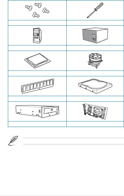
Installation tools and components
|
1 bag of screws |
Philips (cross) screwdriver |
|
PC chassis |
Power supply unit |
|
Intel® LGA1150 CPU |
Intel® LGA1150 compatible CPU Fan |
|
DIMM |
SATA hard disk drive |
|
SATA optical disc drive (optional) |
Graphics card (optional) |
The tools and components in the table above are not included in the motherboard package.
xiv

Chapter 1: Product Introduction |
1 |
|
Product introduction |
1.1Special features
1.1.1Product highlights
LGA1150 socket for 4th generation Intel® Core™ i7/Intel® Core™ i5/Intel® Core™ i3, Pentium® and Celeron® processors
This motherboard supports 4th generation Intel® Core™ i7/Intel® Core™ i5/Intel® Core™ i3, Pentium®, and Celeron® processors in the LGA1150 package. It provides great graphics and system performance with its GPU, dual-channel DDR3 memory slots and PCI Express 2.0/3.0 expansion slots.
Intel® Z87 Express Chipset
Intel® Z87 Express Chipset is a single chipset that supports the LGA1150 socket for 4th generation Intel® Core™ i7/Intel® Core™ i5/Intel® Core™ i3, Pentium® and Celeron® processors. It utilizes the serial point-to-point links, which increases bandwidth and enhances the system’s performance. It natively supports up to six USB 3.0 ports for up to ten times faster transfer rate than USB 2.0 and enables the iGPU function for Intel® integrated graphics performance.
PCI Express® 3.0
PCI Express® 3.0 (PCIe 3.0) is the PCI Express bus standard that provides twice the performance and speed of PCIe 2.0. It provides an optimal graphics performance, unprecedented data speed and seamless transition with its complete backward compatibility to PCIe 1.0/2.0 devices.
Dual-Channel DDR3 1866 / 1600 / 1333 / 1066 MHz Support
The motherboard supports the dual-channel DDR3 memory that features data transfer rates of DDR3 1866 / 1600 / 1333 / 1033 MHz to boost the system’s performance, and to meet the higher bandwidth requirements of 3D graphics, multimedia and Internet applications.
Quad-GPU SLI and Quad GPU CrossFireX™ Support
This motherboard features the most powerful Intel® Z87 platform that optimizes PCIe allocation in multi-GPU SLI and CrossFireX™ solution, giving you a brand-new gaming enjoyment.
Chapter 1

1 Chapter
Intel® Smart Response Technology
Intel® Smart Response Technology, an important part of Green ASUS eco-friendly computing, reduces load and wait time, eliminates unecessary hard drive spin thus lowering power usage, and uses an installed SSD (requires 18.6 GB available space) as a cache for frequently accessed data or applications. It combines SSD performance and hard drive capacity, operating up to six times faster than a hard-drive-only system to boost the system’s overall performance.
*4th Generation Intel® Core™ processors family support Intel® Smart Response Technology.
**An operating system must be installed on the HDD to launch Intel® Smart Response Technology.
***The SSD is reserved for caching function.
Intel® Smart Connect Technology
Your computer can receive fresh updates for selected applications, even when the system is in sleep mode. This means less time waiting for applications to update and sync with the cloud, leading to a more efficient computing experience.
Intel® Rapid Start Technology
Intel® Rapid Start Technology allows your computer to quickly resume from a low-power hibernate state in seconds. Saving your system memory to the designated SSD, it provides your computer a faster wake-up response time, while still keeping the energy use low.
Complete USB 3.0 integration
This motherboard offers you the strategic USB 3.0 accessibility for both the front and rear panels, allowing you to experience the convenience of the latest plug and play connectivity solution of speed up to ten times faster than USB 2.0.
Extra SATA 6.0 Gb/s Support
The Intel® Z87 Express Chipset natively supports the next-generation Serial ATA (SATA) interface, delivering up to 6.0 Gb/s data transfer. ASUS provides extra SATA 6.0 Gb/s ports with enhanced scalability, faster data retrieval, and double the bandwidth of current bus systems.
1.1.2“Ultimate COOL” Thermal Solutions
Thermal Armor with flow valve
ThermalArmor features the exclusive flow gate mechanism that allows you to open or close the Thermal Armor via a button. When the gate is open, it provides an excellent thermal solution for the CPU. When the gate is closed, it focuses air on heatpipes for better heat removal, especially useful for liquid cooling.
Thermal Radar 2
Thermal Radar 2 uses sensors to control motherboard temperatures, automatically adjusting fan speeds for better system stability and power efficiency. It also provides customizable fan management that displays real-time motherboard, CPU and VGAzone cooling status, and promotes extended system longevity, power saving solution, and noise reduction.
|
1-2 |
Chapter 1: Product introduction |

1.1.3“TUF Engine” Power Design
Digital Power Control
ASUS DIGI+ Power Control features the revolutionary and innovative digital VRM, DRAM, and CPU Voltage controllers. These controllers offers ultra-precise memory and voltage tuning for optimal system efficiency, stability and performance.
TUF Components (Choke, Cap. & MOSFET; certified by military-standard)
The motherboard’s TUF components features military-standard robust TUF chokes, titanium solid state capacitors, and MOSFETS. These TUF components support up to a massive 40A rated current, eliminates buzzing noise and vibration, and delivers better performance, and durability during the most extreme usage.
1.1.4“Safe & Stable!” Guardian Angel
TUF Fortifier
The metal base TUF Fortifier strengthens the base of the motherboard and secures the
Thermal Armor and the motherboard in place. It reinforces the motherboard’s PCB to support the Thermal Armor, CPU, VGA card, additional expansion cards, and other peripherals. It also makes the motherboard easier to handle and helps protect your hands.
Dust Defender
Dust Defender provides rear I/O filter and special shields that help reduce dust build-up on critical points within slots and connectors, minimizing any harm to the components’ optimal functions, data transfer efficiency, and system performance.
ESD Guards
ESD (Electrostatic Discharge) Guards provides protection against electrostatic discharges, which can damage the motherboard’s components. The ASUS exclusive Anti-Static chip and circuit design, and the I/O shield provide four times better protection and ensure the motherboard’s lifespan.
MemOK!
MemOK!, the remarkable memory rescue tool, allows you to simply press a button to patch memory issues, ensure memory boot compatibility, determine fail-safe settings, and dramatically improve the system’s bootup.
Chapter 1

1.1.5ASUS EZ DIY
ASUS UEFI BIOS (EZ Mode)
ASUS UEFI BIOS, a UEFI compliant architecture, offers the first mouse-controlled intuitive graphical BIOS interface that goes beyond the traditional keyboard-only BIOS controls, providing you with more flexibility, convenience, and easy to navigate UEFI BIOS than the traditional BIOS versions. It offers you with dual selectable modes and native support for hard drives larger than 2.2 TB.
ASUS UEFI BIOS includes the following new features:
•New My Favorites function allows you to quickly access the frequently used items
•New Quick Note function allows you to take notes in the BIOS environment
•New Last Modified log allows you to view all your modified settings
•F12 BIOS snapshot hotkey
•F3 Shortcut for most accessed information
•ASUS DRAM SPD (Serial Presence Detect) information detecting faulty DIMMs, and helping with difficult POST situations.
ASUS Q-Design
ASUS Q-Design enhances your DIY experience. All of Q-Slot and Q-Shield design speed up and simplify the DIY process.
ASUS Q-shield
ASUS Q-Shield’s special design makes it convenient and easy to install on your motherboard. With better electric conductivity, it ideally protects your motherboard against static electricity and shields it against EMI (Electronic Magnetic Interference).
ASUS Q-connector
ASUS Q-Connector is a unique adapter that allows you to easily connect or disconnect the chassis front panel cables to one module, eliminating the hassle of plugging one cable at a time and making the connection quick and accurate.
DirectKey
DirectKey allows you to conveniently go into the BIOS setup with the press of a button. With this feature, you can enter the BIOS anytime without having to press the <Del> key during POST. It also allows you to shut down or turn on your computer and directly enter the BIOS during boot-up.
1 Chapter
|
1-4 |
Chapter 1: Product introduction |

1.1.6ASUS Exclusive Features
Remote GO!
ASUS Remote GO! leads the way to a more enjoyable home entertainment. With ASUS
Remote GO!, you can wirelessly stream media files to DLNAdevices, remotely control and access your computer using your smart device and easily transfer files between your computer and smart device.
Conveniently use and enjoy these ASUS Remote GO! functions:
•Cloud GO!: Allows you to control files and sync them all across cloud services in a few clicks.
•DLNA Media Hub: Provides support to the latest DLNA standard and allows you to stream media files to a DLNA-supported device.
•Remote Desktop: Allows you to view your computer’s desktop and remotely operate your computer in real-time from your smart device.
•File Transfer:Allows you to transfer files between your computer and smart device.
USB 3.0 Boost
ASUS USB 3.0 Boost, which supports USB 3.0 standard UASP (USB Attached SCSI
Protocol), significantly increases a USB device’s transfer speed up to 170% faster than the already impressive USB 3.0 transfer speed. It automatically accelerates data speeds for compatible USB 3.0 peripherals without the need for any user interaction.
USB Charger+
With a dedicated onboard controller, quick-charge all your smart devices such as smartphones, tablets and more, all up to three times faster, even when the system is powered off, in sleep or hibernation mode.
USB BIOS Flashback
USB BIOS Flashback offers a hassle-free updating solution for your ultimate convenience.
Install a USB storage device containing the BIOS file, press the BIOS Flashback button for about three seconds, and the UEFI BIOS is automatically updated even without entering the existing BIOS or operating system. It also allows you to regularly check for UEFI BIOS updates, and download the latest BIOS automatically.
Network iControl
Network iControl is an intuitive one-step network control center that makes it easier for you to manage your bandwidth and allows you to set, monitor and schedule the bandwidth priorities for your network programs.
AI Suite 3
With its user-friendly interface, ASUS AI Suite 3 consolidates all the exclusive ASUS features into one simple-to-use software package. It allows you to supervise fan speed control, voltage and sensor readings. This all-in-one software offers diverse and ease to use functions, with no need to switch back and forth between different utilities.
Chapter 1

1.1.7Other special features
DisplayPort Support
DisplayPort is a digital display interface standard that delivers up to 10.8 Gbps of bandwidth over standard cables, providing billions of colors and bi-directional communications, thus enabling the fastest refresh rates, and the highest resolution digital display through a single cable. Also, it supports HDCP copy protection for Blu-ray discs. Simply output 3D signals through the connected DisplayPort cable with your 3D display, then you can sit back and enjoy a perfect 3D animation experience.
HDMI Support
High Definition Multimedia Surface (HDMI) is a set of digital video standards that delivers mulit-channel audio and uncompressed digital video up to 4K/2K resolution visuals through a single cable. Supporting HDCP copy protection such as HD DVD and blu-ray discs, HDMI provides you with the highest quality home theater experience.
ErP Ready
The motherboard is European Union’s Energy-related Products (ErP) ready, and ErP requires products to meet certain energy efficiency requirement in regards to energy consumptions. This is in line withASUS vision of creating environment-friendly and energy-efficient products through product design and innovation to reduce carbon footprint of the product and thus mitigate environmental impacts.
1 Chapter
|
1-6 |
Chapter 1: Product introduction |
![]()
1.2Motherboard overview
1.2.1Before you proceed
Take note of the following precautions before you install motherboard components or change any motherboard settings.
• Unplug the power cord from the wall socket before touching any component.
•Before handling components, use a grounded wrist strap or touch a safely grounded object or a metal object, such as the power supply case, to avoid damaging them due to static electricity.
•Hold components by the edges to avoid touching the ICs on them.
•Whenever you uninstall any component, place it on a grounded antistatic pad or in the bag that came with the component.
•Before you install or remove any component, ensure that the ATX power supply is switched off or the power cord is detached from the power supply. Failure to do so may cause severe damage to the motherboard, peripherals, or components.
Chapter 1

1 Chapter
1.2.2Motherboard layout
Refer to 1.2.9 Internal connectors and 2.3.1 Rear I/O connection for more information about rear panel connectors and internal connectors.
|
1-8 |
Chapter 1: Product introduction |

Layout contents
|
Connectors/Jumpers/Slots |
Page |
|
|
1. |
ATX power connectors (24-pin EATXPWR, 8-pin EATX12V) |
1-32 |
|
2. |
CPU, optional, chassis, and assistant fan connectors (4-pin CPU_FAN, |
1-30 |
|
4-pin CPU_OPT, 4-pin CHA_FAN1-4, 3-pin ASST_FAN1-2 ) |
||
|
3. |
LGA1150 CPU socket |
1-10 |
|
4. |
DDR3 DIMM slots |
1-11 |
|
5. |
MemOK! button |
1-22 |
|
6. |
USB 3.0 connector (20-1 pin USB3_34) |
1-27 |
|
7. |
Intel® Z87 Serial ATA 6.0 Gb/s connectors (7-pin SATA6G_1-6 [brown]) |
1-26 |
|
8. |
ASMedia® Serial ATA 6.0 Gb/s connectors (7-pin SATA6G_E12 [beige]) |
1-27 |
|
9. |
DirectKey connector (2-pin DRCT) |
1-34 |
|
10. |
System panel connector (20-8 pin PANEL) |
1-33 |
|
11. |
DirectKey button |
1-23 |
|
12. |
Thermal sensor connectors (T_SENSOR1, T_SENSOR2, T_SENSOR3) |
1-31 |
|
13. |
USB 2.0 connectors (10-1 pin USB1112, USB1314) |
1-29 |
|
14. |
TPM connector (20-1 pin TPM) |
1-34 |
|
15. |
Standby Power LED |
1-25 |
|
16. |
Clear RTC RAM (3-pin CLRTC) |
1-24 |
|
17. |
Digital audio connector (4-1 pin SPDIF_OUT) |
1-28 |
|
18. |
Front panel audio connector (10-1 pin AAFP) |
1-31 |
Chapter 1

1.2.3Central Processing Unit (CPU)
The motherboard comes with a surface mount LGA1150 socket designed for the 4th Generation Intel® Core™ i7 / Intel® Core™ i5 / Intel® Core™ i3, Pentium® and Celeron® processors.
• Ensure that all power cables are unplugged before installing the CPU.
•Ensure that you install the correct CPU designed for LGA1150 only. DO NOT install a CPU designed for LGA1155 and LGA1156 sockets on the LGA1150 socket.
•Upon purchase of the motherboard, ensure that the PnP cap is on the socket and the socket contacts are not bent. Contact your retailer immediately if the PnP cap is missing, or if you see any damage to the PnP cap/socket contacts/motherboard components. ASUS will shoulder the cost of repair only if the damage is shipment/ transit-related.
•Keep the cap after installing the motherboard. ASUS will process Return Merchandise
Authorization (RMA) requests only if the motherboard comes with the cap on the
LGA1150 socket.
•The product warranty does not cover damage to the socket contacts resulting from incorrect CPU installation/removal, or misplacement/loss/incorrect removal of the PnP cap.
1 Chapter
|
1-10 |
Chapter 1: Product introduction |

1.2.4System memory
The motherboard comes with four Double Data Rate 3 (DDR3) Dual Inline Memory Modules (DIMM) slots.
A DDR3 module is notched differently from a DDR or DDR2 module. DO NOT install a DDR or DDR2 memory module to the DDR3 slot.
Recommended memory configurations
Chapter 1

Memory configurations
You may install 2GB, 4GB and 8GB unbuffered and non ECC DDR3 DIMMs into the DIMM sockets.
• You may install varying memory sizes in ChannelAand Channel B. The system maps the total size of the lower-sized channel for the dual-channel configuration.Any excess memory from the higher-sized channel is then mapped for single-channel operation.
•According to Intel® CPU spec, DIMM voltage below 1.65V is recommended to protect the CPU.
•Always install DIMMs with the same CAS latency. For optimum compatibility, we recommend that you obtain memory modules from the same vendor.
•Due to the memory address limitation on 32-bit Windows® OS, when you install 4GB or more memory on the motherboard, the actual usable memory for the OS can be about 3GB or less. For effective use of memory, we recommend that you do any of the following:
a)Use a maximum of 3GB system memory if you are using a 32-bit Windows® OS.
b)Install a 64-bit Windows® OS when you want to install 4GB or more on the motherboard.
c)For more details, refer to the Microsoft® support site at http://support.microsoft. com/kb/929605/en-us.
•This motherboard does not support DIMMs made up of 512Mb (64MB) chips or less (Memory chip capacity counts in Megabit, 8 Megabit/Mb = 1 Megabyte/MB).
• The default memory operation frequency is dependent on its Serial Presence Detect (SPD), which is the standard way of accessing information from a memory module. Under the default state, some memory modules for overclocking may operate at a lower frequency than the vendor-marked value. To operate at the vendor-marked
or at a higher frequency, refer to section 3.5 Ai Tweaker menu for manual memory frequency adjustment.
•For system stability, use a more efficient memory cooling system to support a full memory load (4 DIMMs) or overclocking condition.
•Memory modules with memory frequency higher than 2133MHz and their corresponding timing or the loaded XMP profile is not the JEDEC memory standard.
The stability and compatibility of the memory modules depend on the CPU’s capabilities and other installed devices.
1 Chapter
|
1-12 |
Chapter 1: Product introduction |

SABERTOOTH Z87 Motherboard Qualified Vendors Lists (QVL)
DDR3 2666 MHz capability
|
Vendors |
Part No. |
Size |
SS/DS |
Chip |
Chip |
Timing |
Voltage |
DIMM socket |
|
|
Brand |
NO. |
support |
|||||||
|
(Optional) |
|||||||||
|
2 |
4 |
||||||||
|
G.SKILL |
F3-2666CL10Q-16GBZHD(XMP) |
16GB (4x4GB) |
DS |
— |
— |
9-11-9-27 |
1.65 |
• |
• |
|
GEIL |
GOC332GB2666C11QC(XMP) |
32GB (4x8GB) |
DS |
— |
— |
9-9-9-24 |
1.65 |
• |
• |
DDR3 2500 MHz capability
|
Vendors |
Part No. |
Size |
SS/DS |
Chip |
Chip |
Timing |
Voltage |
DIMM socket |
|
|
Brand |
NO. |
support |
|||||||
|
(Optional) |
|||||||||
|
2 |
4 |
||||||||
|
G.SKILL |
F3-20000CL10Q-16GBZHD(XMP) |
16GB (4x4GB) |
DS |
— |
— |
10-11-11-31 |
1.65 |
• |
• |
DDR3 2400 MHz capability
|
Vendors |
Part No. |
Size |
SS/DS |
Chip |
Chip |
Timing |
Voltage |
DIMM socket |
|
|
Brand |
NO. |
support |
|||||||
|
(Optional) |
|||||||||
|
2 |
4 |
||||||||
|
A-DATA |
AX3U2400GC4G10(XMP) |
4GB |
DS |
— |
— |
10-12-12-31 |
1.65 |
• |
• |
|
Apacer |
78.BAGFL.AFD0C(XMP) |
8GB (2x4GB) |
DS |
— |
— |
11-12-12-30 |
— |
• |
• |
|
Apacer |
783BAGF3.AFD0C(XMP) |
8GB (2x4GB) |
DS |
— |
— |
11-11-11-30 |
— |
• |
• |
|
CORSAIR |
CMZ16GX3M2A2400C10 |
16GB (2x8GB) |
DS |
— |
— |
10-12-12-31 |
1.65 |
• |
• |
|
(Ver4.21) |
|||||||||
|
CORSAIR |
CMZ16GX3M4A2400C9R |
16GB (4x4GB) |
DS |
— |
— |
2400 9-11-11-31 |
1.65 |
• |
• |
|
(Ver4.13)(XMP) |
|||||||||
|
G.SKILL |
F3-19200CL10Q- |
32GB (4x8GB) |
DS |
— |
— |
10-12-12-31 |
1.65 |
• |
• |
|
32GBZHD(XMP) |
|||||||||
|
G.SKILL |
F3-19200CL11Q- |
16GB (4x4GB) |
DS |
— |
— |
11-11-11-31 |
1.65 |
• |
• |
|
16GBZHD(XMP) |
|||||||||
|
G.SKILL |
F3-19200CL11Q- |
16GB (4x4GB) |
DS |
— |
— |
11-11-11-31 |
1.65 |
• |
• |
|
16GBZHD(XMP) |
|||||||||
|
G.SKILL |
F3-19200CL9D- |
4G (2x2GB) |
DS |
— |
— |
9-11-9-28 |
1.65 |
• |
|
|
4GBPIS(XMP) |
|||||||||
|
G.SKILL |
F3-19200CL9Q- |
16GB (4x4GB) |
DS |
— |
— |
9-11-11-31 |
1.65 |
• |
• |
|
16GBZMD(XMP) |
|||||||||
|
GEIL |
GET34GB2400C9DC(XMP) |
4GB (2x2GB) |
DS |
— |
— |
9-11-9-27 |
1.65 |
• |
• |
|
GEIL |
GOC316GB2400C10 |
16GB (4x4GB) |
DS |
— |
— |
10-11-11-30 |
1.65 |
• |
• |
|
QC(XMP) |
|||||||||
|
GEIL |
GOC316GB2400C11 |
16GB (4x4GB) |
DS |
— |
— |
11-11-11-30 |
1.65 |
• |
• |
|
QC(XMP) |
|||||||||
|
Kingston |
KHX2400C11D3K4/ |
8GB (4x2GB) |
SS |
— |
— |
11-13-11-30 |
1.65 |
• |
• |
|
8GX(XMP) |
|||||||||
|
KINGSTON |
KHX24C11K4/16X(XMP) |
16GB (4x4GB) |
DS |
— |
— |
11-13-13-30 |
1.65 |
• |
• |
|
KINGSTON |
KHX24C11T2K2/8X(XMP) |
8GB (2x4GB) |
DS |
— |
— |
— |
1.65 |
• |
• |
|
KINGSTON |
KHX24C11T3K4/32X(XMP) |
32GB (4x8GB) |
DS |
— |
— |
9-9-9-24 |
1.65 |
• |
|
|
Patriot |
PVV34G2400C9K(XMP) |
4GB (2x2GB) |
DS |
— |
— |
9-11-9-27 |
1.66 |
• |
|
|
Patriot |
PXD38G2400C11K(XMP) |
8GB (2x4GB) |
DS |
— |
— |
11-11-11-30 |
1.65 |
• |
• |
|
Patriot |
PXD38G2400C11K(XMP) |
8GB (2x4GB) |
DS |
— |
— |
2400 11-11-11-30 |
1.65 |
• |
• |
|
Team |
TXD38G2400HC |
8GB |
DS |
— |
— |
10-12-12-31 |
1.65 |
• |
• |
|
10QBK(XMP) |
Chapter 1

1 Chapter
DDR3 2200 MHz capability
|
Vendors |
Part No. |
Size |
SS/DS |
Chip |
Chip |
Timing |
Voltage |
DIMM socket |
|
|
Brand |
NO. |
support |
|||||||
|
(Optional) |
|||||||||
|
2 |
4 |
||||||||
|
G.SKILL |
F3-17600CL7D-4GBFLS(XMP) |
4G (2x2GB) |
DS |
— |
— |
7-10-10-28 |
1.65 |
• |
• |
|
GEIL |
GET34GB2200C9DC(XMP) |
4GB (2x2GB) |
DS |
— |
— |
9-10-9-28 |
1.65 |
• |
• |
|
GEIL |
GET38GB2200C9ADC(XMP) |
8GB (2x4GB) |
DS |
— |
— |
9-11-9-28 |
1.65 |
• |
• |
DDR3 2133 MHz capability
|
Vendors |
Part No. |
Size |
SS/DS |
Chip |
Chip |
Timing |
Voltage |
DIMM socket |
|
|
Brand |
NO. |
support |
|||||||
|
(Optional) |
|||||||||
|
2 |
4 |
||||||||
|
A-DATA |
AX3U2133XC4G10(XMP) |
4GB |
DS |
— |
— |
10-11-11-30 |
1.65 |
• |
• |
|
A-DATA |
AX3U2133XW8G10(XMP) |
8GB |
DS |
— |
— |
10-11-11-30 |
1.65 |
• |
• |
|
Apacer |
78.BAGE4.AFD0C(XMP) |
8GB (2x4GB) |
DS |
— |
— |
9-9-9-24 |
— |
• |
• |
|
Apacer |
AHU04GFB33CAQ3R(XMP) |
4GB |
DS |
— |
— |
11-13-13-31 |
— |
• |
• |
|
CORSAIR |
CMD8GX3M2A2133C9 (Ver1.5)(XMP) |
8GB (2x4GB) |
DS |
— |
— |
9-11-10-27 |
1.5 |
• |
• |
|
CORSAIR |
CMT4GX3M2B2133C9(Ver7.1)(XMP) |
4GB (2x2GB) |
DS |
— |
— |
9-10-9-27 |
1.5 |
• |
• |
|
CORSAIR |
CMT4GX3M2B2133C9(XMP) |
4GB (2x2GB) |
DS |
— |
— |
9-10-9-27 |
1.5 |
• |
• |
|
G.SKILL |
F3-17000CL11Q2-64GBZLD(XMP) |
64GB (8x8GB) |
DS |
— |
— |
11-11-11-30 |
1.5 |
• |
• |
|
G.SKILL |
F3-17000CL9Q-16GBXLD(XMP) |
16GB (4x4GB) |
DS |
— |
— |
9-11-9-28 |
1.65 |
• |
• |
|
G.SKILL |
F3-17000CL9Q-16GBZH(XMP) |
16GB (4x4GB) |
DS |
— |
— |
9-11-10-28 |
1.65 |
• |
• |
|
G.SKILL |
F3-17066CL9D-8GBPID(XMP) |
8GB (2x4GB) |
DS |
— |
— |
9-9-9-24 |
1.65 |
• |
• |
|
G.SKILL |
F3-17066CL9Q-16GBTDD(XMP) |
16GB (4x4GB) |
DS |
— |
— |
9-9-9-24 |
1.65 |
• |
|
|
G.SKILL |
F3-2133C11Q-32GZL(XMP) |
32GB (4x8GB) |
DS |
— |
— |
11-11-11-31 |
1.5 |
• |
• |
|
KINGSTON |
KHX2133C11D3K4/16GX(XMP) |
16GB (4x4GB) |
DS |
— |
— |
11-12-11-30 |
1.65 |
• |
• |
|
KINGSTON |
KHX2133C11D3T1K2/16GX(XMP) |
16GB (2x8GB) |
DS |
— |
— |
9-9-9-24 |
1.6 |
• |
|
|
KINGSTON |
KHX21C11T3FK8/64X(XMP) |
64GB (8x8GB) |
DS |
— |
— |
9-9-9-24 |
1.5 |
• |
|
|
OCZ |
OCZ3XTEP2133C9LV4GK |
2GB |
DS |
— |
— |
7-7-7-20 |
1.65 |
• |
|
|
Patriot |
PV316G213C1K(XMP) |
16GB (2x8GB) |
DS |
— |
— |
11-11-11-30 |
1.5 |
• |
• |
|
Patriot |
PVV34G2133C9K(XMP) |
4GB (2x2GB) |
DS |
— |
— |
9-11-9-27 |
1.66 |
• |
• |
|
Patriot |
PXD38G2133C11K(XMP) |
8GB (2x4GB) |
DS |
— |
— |
9-9-9-24 |
1.65 |
• |
• |
|
Patriot |
PXD38G2133C11K(XMP) |
8GB (2x4GB) |
DS |
— |
— |
2133 11-11-11-27 |
1.5 |
• |
• |
|
Team |
TLD38G2133HC11ABK(XMP) |
8GB |
DS |
— |
— |
11-11-11-31 |
1.65 |
• |
• |
|
Team |
TXD34096M2133HC11A-V(XMP) |
4GB |
DS |
— |
— |
11-11-11-31 |
1.65 |
• |
• |
DDR3 2000 MHz capability
|
Vendors |
Part No. |
Size |
SS/ |
Chip |
Chip NO. |
Timing |
Voltage |
DIMM |
|
|
DS |
Brand |
socket |
|||||||
|
support |
|||||||||
|
(Optional) |
|||||||||
|
2 |
4 |
||||||||
|
AEXEA |
AXA3ES2G2000LG28V(XMP) |
2GB |
DS |
— |
— |
— |
1.65 |
• |
• |
|
AEXEA |
AXA3ES4GK2000LG28V(XMP) |
4GB (2x2GB) |
DS |
— |
— |
— |
1.65 |
• |
• |
|
Apacer |
78.AAGD5.9KD(XMP) |
6GB (3x2GB) |
DS |
— |
— |
9-9-9-27 |
— |
• |
• |
|
Asint |
SLA302G08-ML2HB(XMP) |
4GB |
DS |
Hynix |
H5TQ2G83BFRH9C |
9-9-9-27 |
— |
• |
• |
|
G.SKILL |
F3-16000CL9D-4GBRH(XMP) |
4GB (2x2GB) |
DS |
— |
— |
9-9-9-24 |
1.65 |
• |
• |
|
G.SKILL |
F3-16000CL9D-4GBTD(XMP) |
4GB (2x2GB) |
DS |
— |
— |
9-9-9-24 |
1.65 |
• |
|
|
GEIL |
GUP34GB2000C9DC(XMP) |
4GB (2x2GB) |
DS |
— |
— |
9-9-9-28 |
1.65 |
• |
• |
|
Patriot |
PV736G2000ELK(XMP) |
6GB (3x2GB) |
DS |
— |
— |
7-7-7-20 |
1.65 |
• |
• |
|
Patriot |
PX7312G2000ELK(XMP) |
12GB (3x4GB) |
DS |
— |
— |
9-11-9-27 |
1.65 |
• |
• |
|
Silicon Power |
SP002GBLYU200S02(XMP) |
2GB |
DS |
— |
— |
— |
— |
• |
• |
|
Team |
TXD32048M2000C9(XMP) |
2GB |
DS |
Team |
T3D1288RT-20 |
9-9-9-24 |
1.5 |
• |
• |
|
Team |
TXD32048M2000C9-L(XMP) |
2GB |
DS |
Team |
T3D1288LT-20 |
9-9-9-24 |
1.5 |
• |
• |
|
Team |
TXD32048M2000C9-L(XMP) |
2GB |
DS |
Team |
T3D1288RT-20 |
9-9-9-24 |
1.6 |
• |
• |
|
1-14 |
Chapter 1: Product introduction |

DDR3 1866 MHz capability
|
Vendors |
Part No. |
Size |
SS/ |
Chip |
Chip |
Timing |
Voltage |
DIMM |
|
|
DS |
Brand |
NO. |
socket |
||||||
|
support |
|||||||||
|
(Optional) |
|||||||||
|
2 |
4 |
||||||||
|
CORSAIR |
CMD16GX3M2A1866C9 (Ver5.29)(XMP) |
16GB (2x8GB) |
DS |
— |
— |
1866 9-9-9-27 |
1.5 |
• |
|
|
CORSAIR |
CMD16GX3M4A1866C9 (Ver4.13)(XMP) |
16GB (4x4GB) |
DS |
— |
— |
9-10-9-27 |
1.5 |
• |
• |
|
CORSAIR |
CMD16GX3M4A1866C9 (Ver8.16)(XMP) |
16GB (4x4GB) |
DS |
— |
— |
9-10-9-27 |
1.5 |
• |
• |
|
CORSAIR |
CMD8GX3M2A1866C9 (Ver4.13)(XMP) |
8GB (2x4GB) |
DS |
— |
— |
— |
1.5 |
• |
• |
|
CORSAIR |
CMD8GX3M2A1866C9 (Ver5.12)(XMP) |
8GB (2x4GB) |
DS |
— |
— |
9-10-9-27 |
1.5 |
• |
|
|
CORSAIR |
CMD8GX3M2A1866C9 (Ver8.16)(XMP) |
8GB (2x4GB) |
DS |
— |
— |
9-10-9-27 |
1.5 |
• |
|
|
CORSAIR |
CMT32GX3M4X1866C9(Ver3.23)(XMP) |
32GB (4x8GB) |
DS |
— |
— |
9-10-9-27 |
1.5 |
• |
• |
|
CORSAIR |
CMZ16GX3M4X1866C9R (Ver8.16)(XMP) |
16GB (4x4GB) |
DS |
— |
— |
9-10-9-27 |
1.5 |
• |
• |
|
CORSAIR |
CMZ16GX3M4X1866C9R(Ver 8.16)(XMP) |
16GB (4x4GB) |
DS |
— |
— |
9-10-9-27 |
1.5 |
• |
• |
|
CORSAIR |
CMZ32GX3M4X1866C10 (Ver3.23)(XMP) |
32GB (4x8GB) |
DS |
— |
— |
10-11-10-27 |
1.5 |
• |
• |
|
CORSAIR |
CMZ32GX3M4X1866C10(Ver3.23)(XMP) |
32GB (4x8GB) |
DS |
— |
— |
10-11-10-27 |
1.5 |
• |
• |
|
CORSAIR |
CMZ8GX3M2A1866C9 (Ver8.16)(XMP) |
8GB (2x4GB) |
DS |
— |
— |
9-10-9-27 |
1.5 |
• |
• |
|
CORSAIR |
CMZ8GX3M2A1866C9(XMP) |
8GB (2x4GB) |
DS |
— |
— |
9-10-9-27 |
1.5 |
• |
|
|
CORSAIR |
CMZ8GX3M2A1866C9G (Ver5.12)(XMP) |
8GB (2x4GB) |
DS |
— |
— |
1866 9-10-9-27 |
1.5 |
• |
• |
|
Crucial |
BLE4G3D1869DE1XT0.16FMD(XMP) |
4GB |
DS |
— |
— |
9-9-9-27 |
1.5 |
• |
• |
|
G.SKILL |
F3-14900CL10Q2-64GBZLD(XMP) |
64GB (8x8GB) |
DS |
— |
— |
10-11-10-30 |
1.5 |
• |
• |
|
G.SKILL |
F3-14900CL9D-8GBSR(XMP) |
8GB (2x4GB) |
DS |
— |
— |
9-10-9-28 |
1.5 |
• |
• |
|
G.SKILL |
F3-14900CL9Q-16GBXL(XMP) |
16GB (4x4GB) |
DS |
— |
— |
9-10-9-28 |
1.5 |
• |
• |
|
G.SKILL |
F3-14900CL9Q-16GBZL(XMP) |
16GB (4x4GB) |
DS |
— |
— |
9-10-9-28 |
1.5 |
• |
• |
|
G.SKILL |
F3-14900CL9Q-8GBFLD(XMP) |
8GB (2x4GB) |
DS |
— |
— |
9-9-9-24 |
1.6 |
• |
• |
|
G.SKILL |
F3-1866C9Q-32GXM(XMP) |
32GB (4x8GB) |
DS |
— |
— |
9-10-9-28 |
1.5 |
• |
• |
|
KINGSTON |
KHX1866C9D3K2/8GX(XMP) |
8GB (2x4GB) |
DS |
— |
— |
— |
1.65 |
• |
• |
|
Patriot |
PXD34G1866ELK(XMP) |
4GB (2x2GB) |
SS |
— |
— |
9-9-9-24 |
1.65 |
• |
• |
|
Patriot |
PXD38G1866ELK(XMP) |
8GB (2x4GB) |
DS |
— |
— |
9-11-9-27 |
1.65 |
• |
• |
|
Patriot |
PXD38G1866ELK(XMP) |
8GB (2x4GB) |
DS |
— |
— |
9-11-9-27 |
1.65 |
• |
• |
|
Patriot |
PXD38G1866ELK(XMP) |
8GB (2x4GB) |
DS |
— |
— |
1866 9-10-9-27 |
1.5 |
• |
• |
|
Team |
TLD34G1866HC9KBK(XMP) |
4GB |
DS |
— |
— |
9-11-9-27 |
1.5 |
• |
• |
|
Team |
TLD38G1866HC10SBK(XMP) |
8GB |
DS |
— |
— |
10-11-10-30 |
1.5 |
• |
• |
DDR3 1800 MHz capability
|
Vendors |
Part No. |
Size |
SS/DS |
Chip |
Chip |
Timing |
Voltage |
DIMM socket |
|
|
Brand |
NO. |
support (Optional) |
|||||||
|
2 |
4 |
||||||||
|
G.SKILL |
F3-14400CL9D-4GBRL(XMP) |
4GB (2x2GB) |
DS |
— |
— |
9-9-9-24 |
1.6 |
• |
• |
DDR3 1600 MHz capability
|
Vendors |
Part No. |
Size |
SS/ |
Chip |
Chip NO. |
Timing |
Voltage |
DIMM socket |
|
|
DS |
Brand |
support (Optional) |
|||||||
|
2 |
4 |
||||||||
|
A-DATA |
AD3U1600C2G11 |
2GB |
SS |
MICRON |
D9PFJ |
11-11-11-28 — |
• |
• |
|
|
A-DATA |
AD3U1600C4G11 |
4GB |
DS |
MICRON |
D9PFJ |
11-11-11-28 — |
• |
• |
|
|
A-DATA |
AD3U1600W4G11 |
4GB |
SS |
A-DATA |
3WCD-1211A |
11-11-11-28 — |
• |
• |
|
|
A-DATA |
AD3U1600W8G11 |
8GB |
DS |
A-DATA |
3WCD-1211A |
11-11-11-28 |
— |
• |
• |
|
AMD |
AE32G1609U1-U |
2GB |
SS |
AMD |
23EY4587MB6H |
— |
1.5 |
• |
• |
|
AMD |
AE34G1609U2-U |
4GB |
DS |
AMD |
23EY4587MB6H |
— |
1.5 |
• |
• |
|
AMD |
AP38G1608U2K(XMP) |
8GB (2x4GB) |
DS |
— |
— |
9-9-9-28 |
1.65 |
• |
• |
|
Apacer |
78.B1GE3.9L10C |
4GB |
DS |
Apacer |
AM5D5908DEQSCK |
— |
1.65 |
• |
• |
|
Apacer |
78.B1GET.9K00C |
4GB |
SS |
Apacer |
AM5D6008BQQSCK |
11-11-11-28 — |
• |
• |
|
|
Apacer |
78.C1GET.9K10C |
8GB |
DS |
Apacer |
AM5D6008BQQSCK |
11-11-11-31 |
— |
• |
• |
|
Apacer |
AHU04GFA60C9Q1D(XMP) |
4GB |
DS |
— |
— |
9-9-9-27 |
1.65 |
• |
• |
|
Apacer |
AHU04GFA60C9Q3R(XMP) |
4GB |
DS |
— |
— |
11-11-11-28 |
— |
• |
• |
|
Apacer |
AHU08GFA60CBT3R(XMP) |
8GB |
DS |
— |
— |
9-9-9-24 |
— |
• |
• |
|
Asint |
SLA302G08-EGG1C(XMP) |
4GB |
DS |
Asint |
302G08-GG1C |
9-9-9-27 |
— |
• |
• |
(continued on the next page)
Chapter 1

1 Chapter
DDR3 1600 MHz capability
|
Vendors |
Part No. |
Size |
SS/ |
Chip Brand |
Chip NO. |
Timing |
Voltage |
DIMM |
|
|
DS |
socket |
||||||||
|
support |
|||||||||
|
(Optional) |
|||||||||
|
2 |
4 |
||||||||
|
Asint |
SLA302G08-EGJ1C(XMP) |
4GB |
DS |
Asint |
302G08-GJ1C |
9-9-9-27 |
— |
• |
• |
|
Asint |
SLA302G08-EGN1C |
4GB |
DS |
ASint |
302G08-GN1C |
— |
— |
• |
• |
|
Asint |
SLB304G08-EGN1B |
8GB |
DS |
ASint |
304G08-GN1B |
— |
— |
• |
• |
|
Asint |
SLZ302G08-EGN1C |
2GB |
SS |
ASint |
302G08-GN1C |
— |
— |
• |
• |
|
Asint |
SLZ3128M8-EGJ1D(XMP) |
2GB |
DS |
Asint |
3128M8-GJ1D |
— |
— |
• |
• |
|
ATP |
AQ12M64B8BKK0S |
4GB |
DS |
SAMSUNG |
K4B2G08460 |
— |
NO |
• |
• |
|
CORSAIR |
CMD16GX3M2A1600C9 |
16GB (2x8GB) |
DS |
— |
— |
9-9-9-24 |
1.5 |
• |
|
|
(Ver8.21)(XMP) |
|||||||||
|
CORSAIR |
CMD8GX3M2A1600C8 |
8GB (2x4GB) |
DS |
— |
— |
1600 8-8-8-24 |
1.5 |
• |
• |
|
(Ver5.12)(XMP) |
|||||||||
|
CORSAIR |
CMD8GX3M2A1600C9 |
8GB (2x4GB) |
DS |
— |
— |
9-9-9-24 |
1.5 |
• |
• |
|
(Ver2.12)(XMP) |
|||||||||
|
CORSAIR |
CMG4GX3M2A1600C6 |
4GB (2x2GB) |
DS |
— |
— |
6-6-6-18 |
1.65 |
• |
• |
|
CORSAIR |
CML16GX3M4X1600C8(Ver |
16GB (4x4GB) |
DS |
— |
— |
Heat-Sink |
1.5 |
• |
• |
|
2.12)(XMP) |
Package |
||||||||
|
CORSAIR |
CMP6GX3M3A1600C8(XMP) |
6GB (3x2GB) |
DS |
— |
— |
8-8-8-24 |
1.65 |
• |
• |
|
CORSAIR |
CMP6GX3M3A1600C8(XMP) |
6GB (3x2GB) |
DS |
— |
— |
8-8-8-24 |
1.65 |
• |
• |
|
CORSAIR |
CMX6GX3M3C1600C7(XMP) |
6GB (3x2GB) |
DS |
— |
— |
7-8-7-20 |
1.65 |
• |
• |
|
CORSAIR |
CMX8GX3M2A1600C9 |
8GB (2x4GB) |
SS |
— |
— |
9-9-9-24 |
1.65 |
• |
• |
|
(Ver3.19)(XMP) |
|||||||||
|
CORSAIR |
CMZ16GX3M2A1600C10 |
16GB (2x8GB) |
DS |
— |
— |
10-10-10-27 |
1.5 |
• |
• |
|
(Ver.3.24)(XMP) |
|||||||||
|
CORSAIR |
CMZ16GX3M4A1600C9(XMP) |
16GB (4x4GB) |
DS |
— |
— |
9-9-9-24 |
1.5 |
• |
• |
|
CORSAIR |
CMZ32GX3M4X1600C10 |
32GB (4x8GB) |
DS |
— |
— |
10-10-10-27 |
1.5 |
• |
• |
|
(Ver2.2)(XMP) |
|||||||||
|
CORSAIR |
CMZ8GX3M2A1600C8(XMP) |
8GB (2x4GB) |
DS |
— |
— |
8-8-8-24 |
1.5 |
• |
• |
|
CORSAIR |
CMZ8GX3M2A1600C9(XMP) |
8GB (2x4GB) |
DS |
— |
— |
9-9-9-24 |
1.5 |
• |
• |
|
CORSAIR |
CMZ8GX3M4X1600C9(Ver |
8GB (4x2GB) |
SS |
— |
— |
9-9-9-24 |
1.5 |
• |
• |
|
2.12)(XMP) |
|||||||||
|
CORSAIR |
HX3X12G1600C9(XMP) |
12GB (6x2GB) |
DS |
— |
— |
9-9-9-24 |
1.6 |
• |
• |
|
Crucial |
BL12864BN1608.8FF(XMP) |
2GB (2x1GB) |
SS |
— |
— |
8-8-8-24 |
1.65 |
• |
• |
|
Crucial |
BLT4G3D1608DT1TX0.16F |
4GB |
DS |
— |
— |
8-8-8-24 |
1.5 |
• |
• |
|
M(XMP) |
|||||||||
|
EK Memory |
EKM324L28BP8-I16(XMP) |
4GB (2x2GB) |
DS |
— |
— |
9 |
— |
• |
• |
|
EK Memory |
EKM324L28BP8-I16(XMP) |
4GB (2x2GB) |
DS |
— |
— |
9 |
— |
• |
• |
|
Elixir |
M2X2G64CB88G7N-DG(XMP) |
2GB |
SS |
Elixir |
N2CB2G80GN- |
9-9-9-28 |
— |
• |
• |
|
DG |
|||||||||
|
Elixir |
M2X4G64CB8HG5N-DG(XMP) |
4GB |
DS |
Elixir |
N2CB2G80GN- |
9-9-9-28 |
— |
• |
• |
|
DG |
|||||||||
|
Elixir |
M2X8G64CB8HB5N-DG(XMP) |
8GB |
DS |
Elixir |
N2CB4G80BN- |
9-9-9-28 |
1.5 |
• |
• |
|
DG |
|||||||||
|
G.SKILL |
F3-12800CL7D-8GBRH(XMP) |
8GB (2x4GB) |
DS |
— |
— |
7-8-7-24 |
1.6 |
• |
• |
|
G.SKILL |
F3-12800CL7Q-16GBXH(XMP) |
16GB (4x4GB) |
DS |
— |
— |
7-8-7-24 |
1.6 |
• |
• |
|
G.SKILL |
F3-12800CL8D-8GBECO(XMP) |
8GB (2x4GB) |
DS |
— |
— |
8-8-8-24 |
1.35 |
• |
|
|
G.SKILL |
F3-12800CL9D-8GBRL(XMP) |
8GB (2x4GB) |
DS |
— |
— |
9-9-9-24 |
1.5 |
• |
• |
|
G.SKILL |
F3-12800CL9D-8GBSR2(XMP) |
8GB (2x4GB) |
DS |
— |
— |
9-9-9-24 |
1.25 |
• |
• |
|
G.SKILL |
F3-12800CL9Q-16GBXL(XMP) |
16GB (4x4GB) |
DS |
— |
— |
9-9-9-24 |
1.5 |
• |
• |
|
G.Skill |
F3-12800CL9Q-16GBZL(XMP) |
16GB (4x4GB) |
DS |
— |
— |
9-9-9-24 |
1.5 |
• |
• |
|
G.SKILL |
F3-1600C9Q-32GXM(XMP) |
32GB (4x8GB) |
DS |
— |
— |
— |
1.5 |
• |
• |
|
GEIL |
GET316GB1600C9QC(XMP) |
16GB (4x4GB) |
DS |
— |
— |
9-9-9-28 |
1.6 |
• |
• |
|
GEIL |
GUP34GB1600C7DC(XMP) |
4GB (2x2GB) |
DS |
— |
— |
7-7-7-24 |
1.6 |
• |
• |
|
GoodRam |
GR1600D364L9/2G |
2GB |
DS |
GoodRam |
GF1008KC-JN |
— |
— |
• |
• |
|
KINGMAX |
FLGE85F-C8KL9A(XMP) |
2GB |
SS |
KINGMAX |
N/A |
9-9-9-28 |
— |
• |
• |
|
KINGMAX |
FLGF65F-C8KL9A(XMP) |
4GB |
DS |
KINGMAX |
N/A |
9-9-9-28 |
— |
• |
• |
|
KINGSTON |
KHX1600C9D3K3/12GX(XMP) |
12GB (3x4GB) |
DS |
— |
— |
— |
1.65 |
• |
• |
|
KINGSTON |
KHX1600C9D3K3/12GX(XMP) |
12GB (3x4GB) |
DS |
— |
— |
9 |
1.65 |
• |
• |
|
KINGSTON |
KHX1600C9D3K3/6GX(XMP) |
6GB (3x2GB) |
DS |
— |
— |
9 |
1.65 |
• |
• |
|
KINGSTON |
KHX1600C9D3K3/6GX(XMP) |
6GB (3x2GB) |
DS |
— |
— |
9 |
1.65 |
• |
• |
|
KINGSTON |
KHX1600C9D3K4/16GX(XMP) |
16GB (4x4GB) |
DS |
— |
— |
9-9-9-24 |
1.65 |
• |
• |
|
KINGSTON |
KHX1600C9D3K6/24GX(XMP) |
24GB (6x4GB) |
DS |
— |
— |
9 |
1.65 |
• |
• |
|
KINGSTON |
KHX1600C9D3K8/32GX(XMP) |
32GB (8x4GB) |
DS |
— |
— |
9-9-9-27 |
1.65 |
• |
• |
|
KINGSTON |
KHX1600C9D3LK2/8GX(XMP) |
8GB (2x4GB) |
DS |
— |
— |
9-9-9-24 |
1.35 |
• |
• |
|
KINGSTON |
KHX1600C9D3P1K2/8G |
8GB (2x4GB) |
DS |
— |
— |
9 |
1.5 |
• |
• |
|
KINGSTON |
KHX16C10B1K2/16X(XMP) |
16GB (2x8GB) |
DS |
— |
— |
— |
1.5 |
• |
• |
|
KINGSTON |
KHX16C9K2/16 |
16GB (2x8GB) |
DS |
— |
— |
1333-9-9- |
1.5 |
• |
• |
|
9-24 |
|||||||||
|
KINGSTON |
KHX16C9P1K2/16 |
16GB (2x8GB) |
DS |
— |
— |
— |
1.5 |
• |
• |
(continued on the next page)
|
1-16 |
Chapter 1: Product introduction |
![]()
DDR3 1600 MHz capability
|
Vendors |
Part No. |
Size |
SS/ |
Chip Brand |
Chip NO. |
Timing |
Voltage |
DIMM |
|
|
DS |
socket |
||||||||
|
support |
|||||||||
|
(Optional) |
|||||||||
|
2 |
4 |
||||||||
|
KINGSTON |
KVR16N11/4 |
4G |
DS |
Hynix |
H5TQ2G83CFRPBC |
— |
1.5 |
• |
• |
|
KINGTIGER |
KTG2G1600PG3(XMP) |
2GB |
DS |
— |
— |
— |
— |
• |
• |
|
MICRON |
MT16JTF1G64AZ-1G6D1 |
8GB |
DS |
MICRON |
D9PBC |
— |
1.5 |
• |
• |
|
MICRON |
MT16KTF51264AZ-1G6M1 |
4GB |
DS |
MICRON |
D9PFJ |
— |
— |
• |
• |
|
MICRON |
MT8KTF25664AZ-1G6M1 |
2GB |
SS |
MICRON |
D9PFJ |
— |
— |
• |
• |
|
Mushkin |
996805(XMP) |
4GB (2x2GB) |
DS |
— |
— |
6-8-6-24 |
1.65 |
• |
• |
|
Mushkin |
998805(XMP) |
6GB (3x2GB) |
DS |
— |
— |
6-8-6-24 |
1.65 |
• |
• |
|
OCZ |
OCZ3BE1600C8LV4GK |
4GB (2x2GB) |
DS |
— |
— |
8-8-8 |
1.65 |
• |
|
|
Patriot |
PGD316G1600ELK(XMP) |
16GB (2x8GB) |
DS |
— |
— |
— |
1.65 |
• |
• |
|
Patriot |
PGD316G1600ELK(XMP) |
16GB (2x8GB) |
DS |
— |
— |
9-9-9-24 |
1.5 |
• |
• |
|
Patriot |
PGD38G1600ELK(XMP) |
8GB (2x4GB) |
DS |
— |
— |
9-9-9-24 |
1.65 |
• |
• |
|
Patriot |
PGD38G1600ELK(XMP) |
8GB (2x4GB) |
DS |
— |
— |
9-9-9-24 |
1.5 |
• |
|
|
Patriot |
PGS34G1600LLKA |
4GB (2x2GB) |
DS |
— |
— |
7-7-7-20 |
1.7 |
• |
• |
|
Patriot |
PGS34G1600LLKA2 |
4GB (2x2GB) |
DS |
— |
— |
8-8-8-24 |
1.7 |
• |
• |
|
Patriot |
PV316G160C9QKRD(XMP) |
16GB (4x4GB) |
DS |
— |
— |
9-9-9-24 |
1.5 |
• |
• |
|
Patriot |
PV38G160C9KRD(XMP) |
8GB (2x4GB) |
DS |
— |
— |
9-9-9-24 |
1.5 |
• |
• |
|
Patriot |
PVV38G1600LLK(XMP) |
8GB (2x4GB) |
DS |
— |
— |
8-9-8-24 |
1.65 |
• |
• |
|
Patriot |
PX7312G1600LLK(XMP) |
12GB (3x4GB) |
DS |
— |
— |
8-9-8-24 |
1.65 |
• |
• |
|
Patriot |
PXD38G1600LLK(XMP) |
8GB (2x4GB) |
DS |
— |
— |
1600 8-9-8-24 |
1.65 |
• |
• |
|
PSC |
AL9F8L93B-GN2E |
4GB |
SS |
PSC |
A3P4GF3BLF |
— |
— |
• |
• |
|
PSC |
ALAF8L93B-GN2E |
8GB |
DS |
PSC |
A3P4GF3BLF |
— |
— |
• |
• |
|
SanMax |
SMD-4G68HP-16KZ |
4GB |
DS |
Hynix |
H5TQ2G83BFRPBC |
— |
1.5 |
• |
• |
|
SanMax |
SMD-4G68NG-16KK |
4GB |
DS |
ELPIDA |
J2108BDBG-GN-F |
— |
— |
• |
• |
|
Silicon |
SP002GBLTU160V02(XMP) |
2GB |
SS |
S-POWER |
20YT5NG |
9-11-11-28 |
1.5 |
• |
• |
|
Power |
|||||||||
|
Silicon |
SP004GBLTU160V02(XMP) |
4GB |
DS |
S-POWER |
20YT5NG |
9-9-9-24 |
1.5 |
• |
• |
|
Power |
|||||||||
|
Team |
TXD34096M1600HC9-D(XMP) |
4GB |
DS |
Hynix |
H5TC2G83BFRH9A |
9-9-9-24 |
1.5 |
• |
• |
|
Transcend |
JM1600KLH-8G(626633) |
8GB |
DS |
Transcend |
TK963EBF3 |
— |
— |
• |
• |
|
Transcend |
TS1GLK64V6H(620945) |
8GB |
DS |
SAMSUNG |
K4B4G0846B |
— |
— |
• |
• |
DDR3 1333 MHz capability
|
Vendors |
Part No. |
Size |
SS/ |
Chip Brand |
Chip NO. |
Timing |
Voltage |
DIMM |
|
|
DS |
socket |
||||||||
|
support |
|||||||||
|
(Optional) |
|||||||||
|
2 |
4 |
||||||||
|
ACTICA |
ACT1GHU64B8F1333S |
1GB |
SS |
SAMSUNG |
K4B1G0846F |
— |
— |
• |
• |
|
ACTICA |
ACT1GHU72C8G1333S |
1GB |
SS |
SAMSUNG |
K4B1G0846F(ECC) |
— |
— |
• |
• |
|
ACTICA |
ACT2GHU64B8G1333M |
2GB |
DS |
Micron |
D9KPT |
— |
— |
• |
• |
|
ACTICA |
ACT2GHU72D8G1333M |
2GB |
DS |
Micron |
D9KPT(ECC) |
— |
— |
• |
• |
|
ACTICA |
ACT2GHU72D8G1333S |
2GB |
DS |
SAMSUNG |
K4B1G0846F(ECC) |
— |
— |
• |
• |
|
ACTICA |
ACT4GHU64B8H1333H |
4GB |
DS |
Hynix |
H5TQ2G83AFR |
— |
— |
• |
• |
|
ACTICA |
ACT4GHU72D8H1333H |
4GB |
DS |
Hynix |
H5TQ2G83AFR(ECC) |
— |
— |
• |
• |
|
AMD |
AE32G1339U1-U |
2GB |
SS |
AMD |
23EY4587MB3H |
— |
1.5 |
• |
• |
|
AMD |
AE34G1339U2-U |
4GB |
DS |
AMD |
23EY4587MB3H |
— |
1.5 |
• |
• |
|
Apacer |
78.A1GC6.9L1 |
2GB |
DS |
Apacer |
AM5D5808FEQSBG |
9 |
— |
• |
• |
|
Apacer |
78.B1GDE.9L10C |
4GB |
DS |
Apacer |
AM5D5908CEHSBG |
9 |
— |
• |
• |
|
Asint |
SLA302G08-EDJ1C |
2GB |
SS |
ASint |
302G08-DJ1C |
— |
— |
• |
• |
|
Asint |
SLZ302G08-EDJ1C |
4GB |
DS |
ASint |
302G08-DJ1C |
— |
— |
• |
• |
|
ATP |
AQ12M72E8BKH9S |
4GB |
DS |
SAMSUNG |
K4B2G0846C(ECC) |
— |
— |
• |
• |
|
BUFFALO |
D3U1333-1G |
1GB |
SS |
Elpida |
J1108BFBG-DJ-F |
— |
— |
• |
• |
|
BUFFALO |
D3U1333-2G |
2GB |
DS |
Elpida |
J1108BFBG-DJ-F |
— |
• |
• |
|
|
BUFFALO |
D3U1333-4G |
4GB |
DS |
NANYA |
NT5CB256M8BN-CG |
— |
• |
• |
|
|
CORSAIR |
CMV4GX3M2A1333C9 |
4GB (2x2GB) |
SS |
— |
N/A |
9-9-9-24 |
— |
• |
• |
|
CORSAIR |
CMV8GX3M2A1333C9 |
8GB (2x4GB) |
DS |
— |
N/A |
9-9-9-24 |
— |
• |
• |
|
CORSAIR |
CMX8GX3M1A1333C9 (Ver2.2) |
8GB |
DS |
— |
— |
9-9-9-24 |
1.5 |
• |
|
|
CORSAIR |
CMX8GX3M1A1333C9 (Ver3.23) |
8GB |
DS |
— |
— |
9-9-9-24 |
1.5 |
• |
|
|
CORSAIR |
CMX8GX3M2A1333C9(XMP) |
8GB (2x4GB) |
DS |
— |
— |
9-9-9-24 |
1.5 |
• |
• |
|
CORSAIR |
TW3X4G1333C9A |
4GB (2x2GB) |
DS |
— |
— |
9-9-9-24 |
1.5 |
• |
(continued on the next page)
Chapter 1

DDR3 1333 MHz capability
|
Vendors |
Part No. |
Size |
SS/DS |
Chip Brand |
Chip NO. |
Timing |
Voltage |
DIMM |
|
|
socket |
|||||||||
|
support |
|||||||||
|
(Optional) |
|||||||||
|
2 |
4 |
||||||||
|
EK Memory |
EKM324L28BP8-I13 |
4GB (2x2GB) |
DS |
— |
— |
9 |
— |
• |
• |
|
G.SKILL |
F3-10600CL9D-4GBNT |
4GB (2x2GB) |
DS |
G.SKILL |
D3 128M8CE9 2GB |
9-9-9-24 |
1.5 |
• |
• |
|
G.SKILL |
F3-10666CL9D-8GBRL |
8GB (2x4GB) |
DS |
— |
— |
9-9-9-24 |
1.5 |
• |
• |
|
G.SKILL |
F3-10666CL9D-8GBRL |
8GB (2x4GB) |
DS |
— |
— |
9-9-9-24 |
1.5 |
• |
• |
|
G.SKILL |
F3-10666CL9D-8GBXL |
8GB (2x4GB) |
DS |
— |
— |
9-9-9-24 |
1.5 |
• |
• |
|
GEIL |
GB34GB1333C7DC |
4GB (2x2GB) |
DS |
GEIL |
GL1L128M88BA15FW |
7-7-7-24 |
1.5 |
• |
• |
|
GEIL |
GET316GB1333C9QC |
16GB (4x4GB) |
DS |
— |
— |
9-9-9-24 |
1.5 |
• |
• |
|
GEIL |
GG34GB1333C9DC |
4GB (2x2GB) |
DS |
GEIL |
GL1L128M88BA115FW |
9-9-9-24 |
1.3 |
• |
• |
|
GEIL |
GG34GB1333C9DC |
4GB (2x2GB) |
DS |
GEIL |
GL1L128M88BA15B |
9-9-9-24 |
1.3 |
• |
• |
|
GEIL |
GVP34GB1333C9DC |
4GB (2x2GB) |
DS |
— |
— |
9-9-9-24 |
1.5 |
• |
• |
|
GEIL |
GVP38GB1333C9DC |
8GB (2x4GB) |
DS |
— |
— |
9-9-9-24 |
1.5 |
• |
• |
|
GoodRam |
GR1333D364L9/2G |
2GB |
DS |
Qimonda |
IDSH1G-03A1F1C-13H |
— |
— |
• |
• |
|
Hynix |
HMT125U6TFR8A-H9 |
2GB |
DS |
Hynix |
H5TC1G83TFR |
— |
— |
• |
• |
|
INNODISK |
M3UN-2GHJBC09 |
2GB |
SS |
Hynix |
H5TQ2G83CFRH9C |
9-9-9-24 |
— |
• |
• |
|
INNODISK |
M3UN-4GHJAC09 |
4GB |
DS |
Hynix |
H5TQ2G83CFRH9C |
9-9-9-24 |
— |
• |
• |
|
KINGMAX |
FLFE85F-B8KL9 |
2GB |
DS |
KINGMAX |
KFB8FNLXL-BNF-15A |
— |
— |
• |
• |
|
KINGMAX |
FLFE85F-C8KL9 |
2GB |
SS |
KINGMAX |
KFC8FNLBF-GXX-12A |
— |
— |
• |
• |
|
KINGMAX |
FLFE85F-C8KL9 |
2GB |
SS |
KINGMAX |
KFC8FNLXF-DXX-15A |
— |
— |
• |
• |
|
KINGMAX |
FLFE85F-C8KM9 |
2GB |
SS |
Kingmax |
KFC8FNMXF-BXX-15A |
— |
— |
• |
• |
|
KINGMAX |
FLFF65F-C8KL9 |
4GB |
DS |
KINGMAX |
KFC8FNLBF-GXX-12A |
— |
— |
• |
• |
|
KINGMAX |
FLFF65F-C8KL9 |
4GB |
DS |
KINGMAX |
KFC8FNLXF-DXX-15A |
— |
— |
• |
• |
|
KINGMAX |
FLFF65F-C8KM9 |
4GB |
DS |
Kingmax |
KFC8FNMXF-BXX-15A |
— |
— |
• |
• |
|
KINGSTON |
KVR1333D3E9S/4G |
4GB |
DS |
Elpida |
J2108ECSE-DJ-F |
9 |
1.5 |
• |
|
|
KINGSTON |
KVR1333D3N9H/4G |
4GB |
DS |
ELPIDA |
J2108BDBG-GN-F |
— |
1.5 |
• |
• |
|
KINGSTON |
KVR1333D3N9H/8G |
8GB |
DS |
ELPIDA |
J4208EASE-DJ-F |
9-9-9-24 |
1.5 |
• |
• |
|
KINGSTON |
KVR13N9S8H/4 |
4GB |
SS |
ELPIDA |
J4208BBBG-GN-F |
— |
1.5 |
• |
• |
|
KINGTIGER |
F10DA2T1680 |
2GB |
DS |
KINGTIGER |
KTG1333PS1208NST- |
— |
— |
• |
• |
|
C9 |
|||||||||
|
KINGTIGER |
KTG2G1333PG3 |
2GB |
DS |
— |
— |
— |
— |
• |
• |
|
Mach Xtreme |
MXD3U133316GQ |
16GB (4x4GB) |
DS |
— |
— |
— |
— |
• |
• |
|
Mach Xtreme |
MXD3V23332GS |
2GB |
SS |
Mach Xtreme |
C2S46D30-D313 |
— |
— |
• |
• |
|
MICRON |
MT8JTF25664AZ-1G4M1 |
2GB |
SS |
MICRON |
D9PFJ |
— |
— |
• |
• |
|
OCZ |
OCZ3G1333LV4GK |
4GB (2x2GB) |
DS |
— |
— |
9-9-9 |
1.65 |
• |
|
|
OCZ |
OCZ3G1333LV8GK |
8GB (2x4GB) |
DS |
— |
— |
9-9-9 |
1.65 |
• |
|
|
OCZ |
OCZ3G1333LV8GK |
8GB (2x4GB) |
DS |
— |
— |
9-9-9 |
1.65 |
• |
|
|
OCZ |
OCZ3RPR1333C9LV8GK |
8GB (2x4GB) |
DS |
— |
— |
9-9-9 |
1.65 |
• |
|
|
Patriot |
PG38G1333EL(XMP) |
8GB |
DS |
— |
— |
— |
1.5 |
• |
• |
|
Patriot |
PGD316G1333ELK(XMP) |
16GB (2x8GB) |
DS |
— |
— |
9-9-9-24 |
1.5 |
• |
• |
|
Patriot |
PSD32G13332 |
2GB |
DS |
Prtriot |
PM128M8D3BU-15 |
9 |
— |
• |
• |
|
RiDATA |
C304627CB1AG22Fe |
2GB |
DS |
RiDATA |
C304627CB1AG22Fe |
9 |
— |
• |
• |
|
RiDATA |
E304459CB1AG32Cf |
4GB |
DS |
RiDATA |
E304459CB1AG32Cf |
9 |
— |
• |
• |
|
SAMSUNG |
M378B5273CH0-CH9 |
4GB |
DS |
SAMSUNG |
K4B2G0846C |
— |
— |
• |
• |
|
Silicon Power |
SP001GBLTE133S01 |
1GB |
SS |
NANYA |
NT5CB128M8AN-CG |
— |
— |
• |
• |
|
Silicon Power |
SP001GBLTU133S02 |
1GB |
SS |
S-POWER |
10YT3E5 |
9 |
— |
• |
• |
|
Silicon Power |
SP002GBLTU133V02 |
2GB |
SS |
S-POWER |
20YT3NG |
9-9-9-24 |
— |
• |
• |
|
Silicon Power |
SP004GBLTU133V02 |
4GB |
DS |
S-POWER |
20YT3NG |
9-9-9-24 |
— |
• |
|
|
Team |
TED34096M1333HC9 |
4GB |
DS |
Team |
T3D2568LT-13 |
— |
— |
• |
• |
|
Transcend |
JM1333KLH-8G(623654) |
8GB |
DS |
Transcend |
TK963EBF3 |
— |
— |
• |
• |
|
Transcend |
TS1GLK64V3H(620053) |
8GB |
DS |
MICRON |
D9QBJ |
— |
— |
• |
• |
1 Chapter
|
1-18 |
Chapter 1: Product introduction |

Side(s): SS — Single-sided DS — Double-sided DIMM support:
(1)Supports one (1) module inserted into any slot as Single-channel memory configuration. We suggest that you install the module intoA2 slot.
(2)Supports two (2) modules inserted into either the dark brown slots or the beige slots as one pair of Dual-channel memory configuration. We suggest that you install the modules into slots A2 and B2 for better compatibility.
(4)Supports four (4) modules inserted into both the dark brown slots and beige slots as two pairs of Dual-channel memory configuration.
• ASUS exclusively provides hyper DIMM support function.
• Hyper DIMM support is subject to the physical characteristics of individual CPUs. Load the X.M.P. or D.O.C.P. settings in the BIOS for the hyper DIMM support.
•Visit the ASUS website for the latest QVL.
Chapter 1

1.2.5Expansion slots
Unplug the power cord before adding or removing expansion cards. Failure to do so may cause you physical injury and damage motherboard components.
Slot No. Slot Description
1PCIe 2.0 x1_1 slot
2PCIe 3.0/2.0 x16_1 slot
3PCIe 2.0 x1_2 slot
4PCIe 3.0/2.0 x16_2 slot
5PCIe 2.0 x1_3 slot
6PCIe 2.0 x16_3 slot
1 Chapter
|
1-20 |
Chapter 1: Product introduction |

|
PCIe x16_3 |
PCI Express sharing mode |
|||||||||
|
Configuration |
PCIe x16_3 |
PCIe x1_1 |
PCIe x1_2 |
PCIe x1_3 |
eSATA 6Gb/s |
|||||
|
x1 mode |
x1 |
x1 |
x1 |
x1 |
Disabled |
|||||
|
x4 mode |
x4 |
Disabled |
Disabled |
Disabled |
Disabled |
|||||
|
eSATA mode |
x1 |
N/A |
x1 |
x1 |
Enabled |
• We recommend that you provide sufficient power when running CrossFireX™ or SLI™ mode.
•Connect a chassis fan to the motherboard connector labeled CHA_FAN1-4 when using multiple graphics cards for better thermal environment.
IRQ assignments for this motherboard
|
A |
B |
C |
D |
E |
F |
G |
H |
||
|
PCIe x16_1 |
shared |
– |
– |
– |
– |
– |
– |
– |
|
|
PCIe x16_2 |
– |
shared |
– |
– |
– |
– |
– |
– |
|
|
PCIe x16_3 |
shared |
– |
– |
– |
– |
– |
– |
– |
|
|
PCIe x1_1 |
shared |
– |
– |
– |
– |
– |
– |
– |
|
|
PCIe x1_2 |
– |
shared |
– |
– |
– |
– |
– |
– |
|
|
PCIe x1_3 |
– |
– |
shared |
– |
– |
– |
– |
– |
|
|
SMBUS Controller |
– |
– |
shared |
– |
– |
– |
– |
– |
|
|
Intel® SATA Controller |
– |
– |
– |
shared |
– |
– |
– |
– |
|
|
Intel® LAN |
– |
– |
– |
– |
shared |
– |
– |
– |
|
|
USB 2.0 (mid-board) |
shared |
– |
– |
– |
– |
– |
– |
– |
|
|
USB 2.0 (rear I/O) |
– |
– |
– |
– |
– |
– |
– |
shared |
|
|
USB 3.0 |
– |
– |
– |
– |
– |
shared |
– |
– |
|
|
ASM1061 SATA |
– |
– |
shared |
– |
– |
– |
– |
– |
|
|
Controller (rear I/O) |
|||||||||
|
ASM1061 SATA |
– |
– |
shared |
– |
– |
– |
– |
– |
|
|
Controller (mid-board) |
|||||||||
|
HD Audio |
– |
– |
– |
– |
– |
– |
shared |
– |
Chapter 1

1.2.6Onboard buttons
Onboard buttons allow you to fine-tune performance when working on a bare or opencase system. This is ideal for overclockers and gamers who continually change settings to enhance system performance.
1.MemOK! button
Installing DIMMs that are not compatible with the motherboard may cause system boot failure, and the DRAM_LED near the MemOK! switch lights continuously. Press and hold the MemOK! button until the DRAM_LED starts blinking to begin automatic memory compatibility tuning for successful boot.
|
• |
Refer to section 1.2.8 Onboard LEDs for the exact location of the DRAM_LED. |
||||||||||||||||||||||||||||||
|
• |
The DRAM_LED also lights up when the DIMM is not properly installed. Turn off the |
||||||||||||||||||||||||||||||
|
system and reinstall the DIMM before using the MemOK! function. |
|||||||||||||||||||||||||||||||
|
• |
The MemOK! button does not function under Windows® OS environment. |
||||||||||||||||||||||||||||||
|
• |
During the tuning process, the system loads and tests failsafe memory settings. It |
||||||||||||||||||||||||||||||
|
takes about 30 seconds for the system to test one set of failsafe settings. If the test |
|||||||||||||||||||||||||||||||
|
fails, the system reboots and test the next set of failsafe settings. The blinking speed |
|||||||||||||||||||||||||||||||
|
of the DRAM_LED increases, indicating different test processes. |
|||||||||||||||||||||||||||||||
|
• |
Due to memory tuning requirement, the system automatically reboots when each |
||||||||||||||||||||||||||||||
|
timing set is tested. If the installed DIMMs still fail to boot after the whole tuning |
|||||||||||||||||||||||||||||||
|
process, the DRAM_LED lights continuously. Replace the DIMMs with ones |
|||||||||||||||||||||||||||||||
|
recommended in the Memory QVL (Qualified Vendors Lists) in this user manual or on |
|||||||||||||||||||||||||||||||
|
the ASUS website at www.asus.com. |
|||||||||||||||||||||||||||||||
|
Chapter |
• |
If you turn off the computer and replace DIMMs during the tuning process, the system |
|||||||||||||||||||||||||||||
|
to boot and load the BIOS default settings. A message will appear during POST |
|||||||||||||||||||||||||||||||
|
continues memory tuning after turning on the computer. To stop memory tuning, turn |
|||||||||||||||||||||||||||||||
|
off the computer and unplug the power cord for about 5–10 seconds. |
|||||||||||||||||||||||||||||||
|
• |
If your system fails to boot up due to BIOS overclocking, press the MemOK! button |
||||||||||||||||||||||||||||||
|
1 |
reminding you that the BIOS has been restored to its default settings. |
||||||||||||||||||||||||||||||
|
• |
We recommend that you download and update to the latest BIOS version from the |
||||||||||||||||||||||||||||||
|
ASUS website at www.asus.com after using the MemOK! function. |
|||||||||||||||||||||||||||||||
|
1-22 |
Chapter 1: Product introduction |

2.DirectKey button
This feature allows your system to go to the BIOS Setup program with the press of a button. With DirectKey, you can enter the BIOS anytime without having to press the <Delete> key during POST. It also allows you to turn on or turn off your system and conveniently enter the BIOS during boot-up.
Ensure to save your data before using the DirectKey button.
•When the system is on and you press the DirectKey button, your system will shut down. Press the DirectKey button again or the Power-on button to reboot and enter the BIOS directly.
•Turn off your system using the power-on button to allow your system to go through POST (without entering the BIOS) when you reboot your system.
•Refer to section 3.8 Boot Menu for details about setting the DirectKey default function.
Chapter 1

1 Chapter
1.2.7Jumpers
1.Clear RTC RAM (3-pin CLRTC)
This jumper allows you to clear the Real Time Clock (RTC) RAM in CMOS. You can clear the CMOS memory of date, time, and system setup parameters by erasing the CMOS RTC RAM data. The onboard button cell battery powers the RAM data in CMOS, which include system setup information such as system passwords.
To erase the RTC RAM:
1.Turn OFF the computer and unplug the power cord.
2.Move the jumper cap from pins 1-2 (default) to pins 2-3. Keep the cap on pins 2-3 for about 5-10 seconds, then move the cap back to pins 1-2.
3.Plug the power cord and turn ON the computer.
4.Hold down the <Delete> key during the boot process and enter BIOS setup to re-enter data.
Except when clearing the RTC RAM, never remove the cap on CLRTC jumper default position. Removing the cap will cause system boot failure!
• If the steps above do not help, remove the onboard battery and move the jumper again to clear the CMOS RTC RAM data. After the CMOS clearance, reinstall the battery.
•You do not need to clear the RTC when the system hangs due to overclocking. For system failure due to overclocking, use the C.P.R. (CPU Parameter Recall) feature. Shut down and reboot the system so the BIOS can automatically reset parameter settings to default values.
•Due to the chipset behavior, AC power off is required to enable C.P.R. function. You must turn off and on the power supply or unplug and plug the power cord before rebooting the system.
|
1-24 |
Chapter 1: Product introduction |

1.2.8Onboard LEDs
1.POST State LEDs
The POST State LEDs provide the status of these key components during POST (Power-On-Self Test): CPU, memory modules, VGA card, and hard disk drive.s If an error is found, the critical component’s LED stays lit up until the problem is solved.
2.Standby Power LED
The motherboard comes with a standby power LED. The green LED lights up to indicate that the system is ON, in sleep mode, or in soft off mode. This is a reminder that you should shut down the system and unplug the power cable before removing or plugging in any motherboard component. The illustration below shows the location of the onboard LED.
Chapter 1

1.2.9Internal connectors
1.Intel® Z87 SerialATA 6.0 Gb/s connectors (7-pin SATA6G_1-6 [brown])
These connectors connect to Serial ATA 6.0 Gb/s hard disk drives via Serial ATA 6.0 Gb/s signal cables.
If you installed Serial ATA hard disk drives, you can create a RAID 0, 1, 5, and 10 configuration with the Intel® Rapid Storage Technology through the onboard Intel® Z87 chipset.
•These connectors are set to [AHCI Mode] by default. If you intend to create a Serial ATA RAID set using these connectors, set the SATA Mode item in the BIOS to [RAID Mode]. Refer to section 3.6.3 SATA Configuration for details.
•Before creating a RAID set, refer to section 5.1 RAID configurations or the manual bundled in the motherboard support DVD.
1 Chapter
|
1-26 |
Chapter 1: Product introduction |
![]()
2.ASMedia® Serial ATA6.0 Gb/s connectors (7-pin SATA6G_E12 [beige])
These connectors connect to Serial ATA 6.0 Gb/s hard disk drives via Serial ATA 6.0 Gb/s signal cables.
•ASMedia storage controller can only support AHCI mode.
•These SATA ports are for data drives only.
3.USB 3.0 connector (20-1 pin USB3_34)
This connector allows you to connect a USB 3.0 module for additional USB 3.0 front or rear panel ports. With an installed USB 3.0 module, you can enjoy all the benefits of
USB 3.0 including faster data transfer speeds of up to 5Gbps, faster charging time for
USB-chargeable devices, optimized power efficiency, and backward compatibility with
USB 2.0.
•The USB 3.0 module is purchased separately.
•These connectors are based on xHCI specification. We recommend you to install the related driver to fully use the USB 3.0 ports under Windows® 7 or later Windows® OS.
Chapter 1

4.Digital audio connector (4-1 pin SPDIF_OUT)
This connector is for an additional Sony/Philips Digital Interface (S/PDIF) port. Connect the S/PDIF Out module cable to this connector, then install the module to a slot opening at the back of the system chassis.
The S/PDIF module is purchased separately.
1 Chapter
|
1-28 |
Chapter 1: Product introduction |

5.USB 2.0 connectors (10-1 pin USB1112; USB1314)
These connectors are for USB 2.0 ports. Connect the USB module cable to any of these connectors, then install the module to a slot opening at the back of the system chassis. These USB connectors comply with USB 2.0 specification that supports up to
48 MBps connection speed.
DO NOT connect a 1394 cable to the USB connectors. Doing so will damage the motherboard!
You can connect the front panel USB cable to the ASUS Q-Connector (USB, dark brown) first, and then install the Q-Connector (USB) to the USB connector onboard if your chassis supports front panel USB ports.
The USB 2.0 module is purchased separately.
Chapter 1

6.CPU, optional, chassis, and assistant fan connectors
(4-pin CPU_FAN; 4-pin CPU_OPT; 4-pin CHA_FAN1-4; 3-pinASST_FAN1-2)
Connect the fan cables to the fan connectors on the motherboard, ensuring that the black wire of each cable matches the ground pin of the connector.
1 Chapter
•DO NOT forget to connect the fan cables to the fan connectors. Insufficient air flow inside the system may damage the motherboard components. These are not jumpers! Do not place jumper caps on the fan connectors!
•Ensure that the CPU FAN cable is securely installed to the CPU fan connector.
•The CPU_FAN connector supports the CPU fan of maximum 1A (12 W) fan power.
•The CPU_FAN, CHA_FAN and ASST_FAN connectors support the TUF Thermal Radar 2 feature.
•To fully use the fan control function, ensure that you connect only an assistant fan to the ASST_FAN connectors.
|
1-30 |
Chapter 1: Product introduction |

7.Front panel audio connector (10-1 pinAAFP)
This connector is for a chassis-mounted front panel audio I/O module that supports either HD Audio or legacy AC`97 audio standard. Connect one end of the front panel audio I/O module cable to this connector.
•We recommend that you connect a high-definition front panel audio module to this connector to avail of the motherboard’s high-definition audio capability.
•If you want to connect a high-definition or anAC’97 front panel audio module to this connector, set the Front Panel Type item in the BIOS setup to [HD] or [AC97].
8.Thermal Sensor connectors (2-pin T_SENSOR1; T_SENSOR2;T_SENSOR3)
These connectors are for the thermistor cables that monitor the temperature of the devices and the critical components inside the motherboard. Connect the thermistor cable and place the sensor on the device or the motherboard’s component to detect its temperature.
Chapter 1

9.ATX power connectors (24-pin EATXPWR; 8-pin EATX12V)
These connectors are for ATX power supply plugs. The power supply plugs are designed to fit these connectors in only one orientation. Find the proper orientation and push down firmly until the connectors completely fit.
For a fully configured system, we recommend that you use a power supply unit (PSU) that complies withATX 12 V Specification 2.0 (or later version) and provides a minimum power of 350 W.
DO NOT forget to connect the 4-pin/8-pin EATX12 V power plug. Otherwise, the system will not boot.
We recommend that you use a PSU with a higher power output when configuring a system with more power-consuming devices. The system may become unstable or may not boot up if the power is inadequate.
If you want to use two or more high-end PCI Express x16 cards, use a PSU with 1000W power or above to ensure the system stability.
If you are uncertain about the minimum power supply requirement for your system, refer to the Recommended Power Supply Wattage Calculator at http://support.asus. com/PowerSupplyCalculator/PSCalculator.aspx?SLanguage=en-us for details.
1 Chapter
|
1-32 |
Chapter 1: Product introduction |

10.System panel connector (20-8 pin PANEL)
This connector supports several chassis-mounted functions.
•System power LED (2-pin PLED)
This 2-pin connector is for the system power LED. Connect the chassis power LED cable to this connector. The system power LED lights up when you turn on the system power, and blinks when the system is in sleep mode.
•Hard disk drive activity LED (2-pin IDE_LED)
This 2-pin connector is for the HDD Activity LED. Connect the HDD Activity LED cable to this connector. The IDE LED lights up or flashes when data is read from or written to the HDD.
•System warning speaker (4-pin SPEAKER)
This 4-pin connector is for the chassis-mounted system warning speaker. The speaker allows you to hear system beeps and warnings.
•ATX power button/soft-off button (2-pin PWRSW)
This connector is for the system power button. Pressing the power button turns the system on or puts the system in sleep or soft-off mode depending on the operating system settings. Pressing the power switch for more than four seconds while the system is ON turns the system OFF.
•Reset button (2-pin RESET)
This 2-pin connector is for the chassis-mounted reset button for system reboot without turning off the system power.
Chapter 1

1 Chapter
11.TPM connector (20-1 pin TPM)
This connector supports a Trusted Platform Module (TPM) system, which securely store keys, digital certificates, passwords and data.ATPM system also helps enhance the network security, protects digital identities, and ensures platform integrity.
12.DirectKey connector (2-pin DRCT)
This connector is for the chassis-mounted button that supports the DirectKey function. Connect the button cable that supports DirectKey, from the chassis to this connector on the motherboard.
Ensure that your chassis comes with the extra button cable that supports the DirectKey feature. Refer to the technical documentation that came with the chassis for details.
|
1-34 |
Chapter 1: Product introduction |

Chapter 2: Basic installation
|
Basic installation |
2 |
|
|
2.1 |
Building your PC system |
|
|
2.1.1 |
Motherboard installation |
|
|
The diagrams in this section are for reference only. The motherboard layout may vary with |
||
|
models, but the installation steps are the same for all models. |
1.Install the ASUS Q-Shield to the chassis rear I/O panel.
2.Place the motherboard into the chassis, ensuring that its rear I/O ports are aligned to the chassis’ rear I/O panel.
Chapter 2

2 Chapter
3.Place nine screws into the holes indicated by circles to secure the motherboard to the chassis.
DO NOT overtighten the screws! Doing so can damage the motherboard.
|
2-2 |
Chapter 2: Basic installation |
 Loading…
-
Страница 1
Motherboard SABERTOOTH Z87[…]
-
Страница 2
ii First Edition April 2013 Copyright © 2013 ASUST eK COMPUTER INC. All Rights Reserved. No part of this manual, including the products and software described in it, may be reproduced, transmitted, transcribed, stored in a retrieval system, or translated into any language in any form or by any means, except documentation kept by the purchaser for […]
-
Страница 3
iii Contents Safety information ………………………………………………………………………………………… vi About this guide ………………………………………………………………………………………….. vii SABERTOOTH Z87 specications summary ………………………………………..[…]
-
Страница 4
iv 2.3 Motherboard rear and audio connections ……………………………………… 2-12 2.3.1 Rear I/O connection ………………………………………………………… 2-12 2.3.2 Audio I/O connections ……………………………………………………… 2-14 2.4 Starting up for the rst time ………………….[…]
-
Страница 5
v 4.2.1 Running the support DVD ………………………………………………….. 4-1 4.2.2 Obtaining the software manuals ………………………………………….. 4-3 4.3 Software information ……………………………………………………………………… 4-4 4.3.1 AI Suite 3 …………………………….[…]
-
Страница 6
vi Safety information Electrical safety T o prevent electrical shock hazard, disconnect the power cable from the electrical outlet before relocating the system. When adding or removing devices to or from the system, ensure that the power cables for the devices are unplugged before the signal cables are connected. If possible, disconnect all power c[…]
-
Страница 7
vii About this guide This user guide contains the information you need when installing and conguring the motherboard. How this guide is organized This guide contains the following parts: • Chapter 1: Product introduction This chapter describes the features of the motherboard and the new technology it supports. It includes description of the sw[…]
-
Страница 8
viii Conventions used in this guide T o ensure that you perform certain tasks properly , take note of the following symbols used throughout this manual. DANGER/W ARNING: Information to prevent injury to yourself when trying to complete a task. CAUTION: Information to prevent damage to the components when trying to complete a task IMPORT ANT : Instr[…]
-
Страница 9
ix SABERTOOTH Z87 specications summary CPU LGA1 150 socket for the 4th Generation Intel ® Core™ i7/Intel ® Core™i5/Intel ® Core™ i3, Pentium ® and Celeron ® processors Supports 22nm CPU Supports Intel ® T urbo Boost T echnology 2.0* * The Intel ® T urbo Boost T echnology 2.0 support depends on the CPU types. Chipset Intel ® Z87 Exp[…]
-
Страница 10
x Storage Intel ® Z87 Express Chipset — 6 x SA T A 6.0 Gb/s ports (brown) with RAID 0, 1, 5 and 10 support — Supports Intel ® Smart Response T echnology , Intel ® Rapid Start T echnology , Intel ® Smart Connect T echnology* 2 x ASMedia ® SA T A 6Gb/s controllers** — 2 x SA T A 6.0 Gb/s ports (beige) — 2 x eSA T A 6.0 Gb/s ports (red) * These f[…]
-
Страница 11
xi (continued on the next page) SABERTOOTH Z87 specications summary Other Special Features — USB 3.0 Boost featuring speedy USB 3.0 transmission — USB BIOS Flashback — USB Charger+ — Network iControl — ASUS UEFI BIOS EZ Mode featuring friendly graphics user interface — AI Suite 3 — Remote GO! — ASUS Q-Connector — ASUS Q-Shield — ASUS Q-LED (CPU,[…]
-
Страница 12
xii Internal I/O connectors 1 x Clear CMOS jumper Front panel audio connector (AAFP) System panel (Q-Connector) 24-pin EA TX Power connector 8-pin EA TX 12V Power connector BIOS features 64 Mb Flash ROM, UEFI AMI BIOS, PnP , DMI 2.7, WfM 2.0, SM BIOS 2.7, ACPI 5.0, Multi-language BIOS, ASUS EZ Flash 2, ASUS CrashFree BIOS 3, My Favorites, Quick Not[…]
-
Страница 13
xiii User Manual ASUS SABERTOOTH Z87 motherboard T echnical documentations, certication and warranty card Support DVD 4 x Serial A T A 6.0 Gb/s cables 1 x ASUS SLI™ bridge connector 1 x ASUS Q-Shield 1 x 2-in-1 ASUS Q-Connector kit 2 x 35mm Assistant fans 2 x short fan screws 4 x long fan screws 3 x PCIe x16 slot covers 3 x PCIe x1 slot covers[…]
-
Страница 14
xiv Installation tools and components 1 bag of screws Philips (cross) screwdriver PC chassis Power supply unit Intel ® LGA1 150 CPU Intel ® LGA1 150 compatible CPU Fan DIMM SA T A hard disk drive SA T A optical disc drive (optional) Graphics card (optional) The tools and components in the table above are not included in the motherboard package.[…]
-
Страница 15
ASUS SABERT OOTH Z87 1-1 Chapter 1 Product introduction 1 1.1 Special features 1.1.1 Product highlights LGA1 150 socket for 4th generation Intel ® Core™ i7/Intel ® Core™ i5/Intel ® Core™ i3, Pentium ® and Celeron ® processors This motherboard supports 4th generation Intel ® Core™ i7/Intel ® Core™ i5/Intel ® Core™ i3, Pentium ® […]
-
Страница 16
1-2 Chapter 1: Product introduction Chapter 1 Intel ® Smart Response T echnology Intel ® Smart Response T echnology , an important part of Green ASUS eco-friendly computing, reduces load and wait time, eliminates unecessary hard drive spin thus lowering power usage, and uses an installed SSD (requires 18.6 GB available space) as a cache for frequ[…]
-
Страница 17
ASUS SABERT OOTH Z87 1-3 Chapter 1 1.1.3 “TUF Engine” Power Design Digital Power Control ASUS DIGI+ Power Control features the revolutionary and innovative digital VRM, DRAM, and CPU V oltage controllers. These controllers offers ultra-precise memory and voltage tuning for optimal system efciency , stability and performance. TUF Components ([…]
-
Страница 18
1-4 Chapter 1: Product introduction Chapter 1 1.1.5 ASUS EZ DIY ASUS UEFI BIOS (EZ Mode) ASUS UEFI BIOS, a UEFI compliant architecture, offers the rst mouse-controlled intuitive graphical BIOS interface that goes beyond the traditional keyboard-only BIOS controls, providing you with more exibility , convenience, and easy to navigate UEFI BIOS[…]
-
Страница 19
ASUS SABERT OOTH Z87 1-5 Chapter 1 1.1.6 ASUS Exclusive Features Remote GO! ASUS Remote GO! leads the way to a more enjoyable home entertainment. With ASUS Remote GO!, you can wirelessly stream media les to DLNA devices, remotely control and access your computer using your smart device and easily transfer les between your computer and smart d[…]
-
Страница 20
1-6 Chapter 1: Product introduction Chapter 1 1.1.7 Other special features DisplayPort Support DisplayPort is a digital display interface standard that delivers up to 10.8 Gbps of bandwidth over standard cables, providing billions of colors and bi-directional communications, thus enabling the fastest refresh rates, and the highest resolution digita[…]
-
Страница 21
ASUS SABERT OOTH Z87 1-7 Chapter 1 • Unplug the power cord from the wall socket before touching any component. • Before handling components, use a grounded wrist strap or touch a safely grounded object or a metal object, such as the power supply case, to avoid damaging them due to static electricity . • Hold components by the edges to avoid t[…]
-
Страница 22
1-8 Chapter 1: Product introduction Chapter 1 Refer to 1.2.9 Internal connectors and 2.3.1 Rear I/O connection for more information about rear panel connectors and internal connectors. 1.2.2 Motherboard layout[…]
-
Страница 23
ASUS SABERT OOTH Z87 1-9 Chapter 1 Layout contents Connectors/Jumpers/Slots Page 1. A TX power connectors (24-pin EA TXPWR, 8-pin EA TX12V) 1-32 2. CPU, optional, chassis, and assistant fan connectors (4-pin CPU_F AN, 4-pin CPU_OPT , 4-pin CHA_F AN1-4, 3-pin ASST_F AN1-2 ) 1-30 3. LGA1 150 CPU socket 1-10 4. DDR3 DIMM slots 1-1 1 5. MemOK! button 1[…]
-
Страница 24
1-10 Chapter 1: Product introduction Chapter 1 1.2.3 Central Processing Unit (CPU) The motherboard comes with a surface mount LGA1 150 socket designed for the 4th Generation Intel ® Core™ i7 / Intel ® Core™ i5 / Intel ® Core™ i3, Pentium ® and Celeron ® processors. • Ensure that all power cables are unplugged before installing the CPU.[…]
-
Страница 25
ASUS SABERT OOTH Z87 1-1 1 Chapter 1 Recommended memory congurations 1.2.4 System memory The motherboard comes with four Double Data Rate 3 (DDR3) Dual Inline Memory Modules (DIMM) slots. A DDR3 module is notched differently from a DDR or DDR2 module. DO NOT install a DDR or DDR2 memory module to the DDR3 slot.[…]
-
Страница 26
1-12 Chapter 1: Product introduction Chapter 1 • Y ou may install varying memory sizes in Channel A and Channel B. The system maps the total size of the lower-sized channel for the dual-channel conguration. Any excess memory from the higher-sized channel is then mapped for single-channel operation. • According to Intel ® CPU spec, DIMM volt[…]
-
Страница 27
ASUS SABERT OOTH Z87 1-13 Chapter 1 SABERTOOTH Z87 Motherboard Qualied V endors Lists (QVL) DDR3 2666 MHz capability V endors Part No. Size SS/DS Chip Brand Chip NO. Timing V oltage DIMM socket support (Optional) 2 4 G.SKILL F3-2666CL10Q-16GBZHD(XMP) 16GB (4x4GB) DS — — 9-1 1-9-27 1.65 • • GEIL GOC332GB2666C1 1QC(XMP) 32GB (4x8GB) DS — — 9-9[…]
-
Страница 28
1-14 Chapter 1: Product introduction Chapter 1 DDR3 2200 MHz capability V endors Part No. Size SS/DS Chip Brand Chip NO. Timing Voltage DIMM socket support (Optional) 2 4 G.SKILL F3-17600CL7D-4GBFLS(XMP) 4G (2x2GB) DS — — 7-10-10-28 1.65 • • GEIL GET34GB2200C9DC(XMP) 4GB (2x2GB) DS — — 9-10-9-28 1.65 • • GEIL GET38GB2200C9ADC(XMP) 8GB (2x4G[…]
-
Страница 29
ASUS SABERT OOTH Z87 1-15 Chapter 1 DDR3 1866 MHz capability V endors Part No. Size SS/ DS Chip Brand Chip NO. Timing V oltage DIMM socket support (Optional) 2 4 CORSAIR CMD16GX3M2A1866C9 (V er5.29)(XMP) 16GB (2x8GB) DS — — 1866 9-9-9-27 1.5 • CORSAIR CMD16GX3M4A1866C9 (V er4.13)(XMP) 16GB (4x4GB) DS — — 9-10-9-27 1.5 • • CORSAIR CMD16GX3M4A1[…]
-
Страница 30
1-16 Chapter 1: Product introduction Chapter 1 DDR3 1600 MHz capability (continued on the next page) V endors Part No. Size SS/ DS Chip Brand Chip NO. Timing Voltage DIMM socket support (Optional) 2 4 Asint SLA302G08-EGJ1C(XMP) 4GB DS Asint 302G08-GJ1C 9-9-9-27 — • • Asint SLA302G08-EGN1C 4GB DS ASint 302G08-GN1C — — • • Asint SLB304G08-EGN[…]
-
Страница 31
ASUS SABERT OOTH Z87 1-17 Chapter 1 V endors Part No. Size SS/ DS Chip Brand Chip NO. Timing V oltage DIMM socket support (Optional) 2 4 KINGSTON KVR16N1 1/4 4G DS Hynix H5TQ2G8 3CFRPBC — 1.5 • • KINGTIGER KTG2G1600PG3(XMP) 2GB DS — — — — • • MICRON MT16JTF1G64AZ-1G6D1 8GB DS MICRON D9PBC — 1.5 • • MICRON MT16KTF51264AZ-1G6M1 4GB DS MIC[…]
-
Страница 32
1-18 Chapter 1: Product introduction Chapter 1 DDR3 1333 MHz capability V endors Part No. Size SS/DS Chip Brand Chip NO. Timing Voltage DIMM socket support (Optional) 2 4 EK Memory EKM324L28BP8-I13 4GB (2x2GB) DS — — 9 — • • G.SKILL F3-10600CL9D-4GBNT 4GB (2x2GB) DS G.SKILL D3 128M8CE9 2GB 9-9-9-24 1.5 • • G.SKILL F3-10666CL9D-8GBRL 8GB (2x[…]
-
Страница 33
ASUS SABERT OOTH Z87 1-19 Chapter 1 Side(s): SS — Single-sided DS — Double-sided DIMM support: (1) Supports one (1) module inserted into any slot as Single-channel memory conguration. We suggest that you install the module into A2 slot. (2) Supports two (2) modules inserted into either the dark brown slots or the beige slots as one pair of Dual-[…]
-
Страница 34
1-20 Chapter 1: Product introduction Chapter 1 1.2.5 Expansion slots Unplug the power cord before adding or removing expansion cards. Failure to do so may cause you physical injury and damage motherboard components. Slot No. Slot Description 1 PCIe 2.0 x1_1 slot 2 PCIe 3.0/2.0 x16_1 slot 3 PCIe 2.0 x1_2 slot 4 PCIe 3.0/2.0 x16_2 slot 5 PCIe 2.0 x1_[…]
-
Страница 35
ASUS SABERT OOTH Z87 1-21 Chapter 1 • We recommend that you provide sufcient power when running CrossFireX™ or SLI™ mode. • Connect a chassis fan to the motherboard connector labeled CHA_F AN1-4 when using multiple graphics cards for better thermal environment. IRQ assignments for this motherboard PCIe x16_3 Conguration PCI Express sh[…]
-
Страница 36
1-22 Chapter 1: Product introduction Chapter 1 1.2.6 Onboard buttons Onboard buttons allow you to ne-tune performance when working on a bare or open- case system. This is ideal for overclockers and gamers who continually change settings to enhance system performance. 1. MemOK! button Installing DIMMs that are not compatible with the motherboard […]
-
Страница 37
ASUS SABERT OOTH Z87 1-23 Chapter 1 Ensure to save your data before using the DirectKey button. 2. DirectKey button This feature allows your system to go to the BIOS Setup program with the press of a button. With DirectKey , you can enter the BIOS anytime without having to press the <Delete> key during POST . It also allows you to turn on or […]
-
Страница 38
1-24 Chapter 1: Product introduction Chapter 1 1.2.7 Jumpers 1. Clear RTC RAM (3-pin CLRTC) This jumper allows you to clear the Real T ime Clock (RTC) RAM in CMOS. Y ou can clear the CMOS memory of date, time, and system setup parameters by erasing the CMOS RTC RAM data. The onboard button cell battery powers the RAM data in CMOS, which include sys[…]
-
Страница 39
ASUS SABERT OOTH Z87 1-25 Chapter 1 1.2.8 Onboard LEDs 1. POST State LEDs The POST State LEDs provide the status of these key components during POST (Power-On-Self T est): CPU, memory modules, VGA card, and hard disk drive.s If an error is found, the critical component’s LED stays lit up until the problem is solved. 2. Standby Power LED The mothe[…]
-
Страница 40
1-26 Chapter 1: Product introduction Chapter 1 1.2.9 Internal connectors 1. Intel ® Z87 Serial A T A 6.0 Gb/s connectors (7-pin SA T A6G_1-6 [brown]) These connectors connect to Serial A T A 6.0 Gb/s hard disk drives via Serial A T A 6.0 Gb/s signal cables. If you installed Serial A T A hard disk drives, you can create a RAID 0, 1, 5, and 10 con?[…]
-
Страница 41
ASUS SABERT OOTH Z87 1-27 Chapter 1 2. ASMedia ® Serial A T A 6.0 Gb/s connectors (7-pin SA T A6G_E12 [beige]) These connectors connect to Serial A T A 6.0 Gb/s hard disk drives via Serial A T A 6.0 Gb/s signal cables. • ASMedia storage controller can only support AHCI mode. • These SA T A ports are for data drives only . 3. USB 3.0 connector […]
-
Страница 42
1-28 Chapter 1: Product introduction Chapter 1 4. Digital audio connector (4-1 pin SPDIF_OUT) This connector is for an additional Sony/Philips Digital Interface (S/PDIF) port. Connect the S/PDIF Out module cable to this connector , then install the module to a slot opening at the back of the system chassis. The S/PDIF module is purchased separately[…]
-
Страница 43
ASUS SABERT OOTH Z87 1-29 Chapter 1 DO NOT connect a 1394 cable to the USB connectors. Doing so will damage the motherboard! Y ou can connect the front panel USB cable to the ASUS Q-Connector (USB, dark brown) rst, and then install the Q-Connector (USB) to the USB connector onboard if your chassis supports front panel USB ports. The USB 2.0 modu[…]
-
Страница 44
1-30 Chapter 1: Product introduction Chapter 1 6. CPU, optional, chassis, and assistant fan connectors (4-pin CPU_F AN; 4-pin CPU_OPT ; 4-pin CHA_F AN1-4; 3-pin ASST_F AN1-2) Connect the fan cables to the fan connectors on the motherboard, ensuring that the black wire of each cable matches the ground pin of the connector . • DO NOT forget to conn[…]
-
Страница 45
ASUS SABERT OOTH Z87 1-31 Chapter 1 7. Front panel audio connector (10-1 pin AAFP) This connector is for a chassis-mounted front panel audio I/O module that supports either HD Audio or legacy AC`97 audio standard. Connect one end of the front panel audio I/O module cable to this connector . • We recommend that you connect a high-denition front[…]
-
Страница 46
1-32 Chapter 1: Product introduction Chapter 1 • For a fully congured system, we recommend that you use a power supply unit (PSU) that complies with A TX 12 V Specication 2.0 (or later version) and provides a minimum power of 350 W . • DO NOT forget to connect the 4-pin/8-pin EA TX12 V power plug. Otherwise, the system will not boot. • […]
-
Страница 47
ASUS SABERT OOTH Z87 1-33 Chapter 1 • System power LED (2-pin PLED) This 2-pin connector is for the system power LED. Connect the chassis power LED cable to this connector . The system power LED lights up when you turn on the system power , and blinks when the system is in sleep mode. • Hard disk drive activity LED (2-pin IDE_LED) This 2-pin co[…]
-
Страница 48
1-34 Chapter 1: Product introduction Chapter 1 1 1. TPM connector (20-1 pin TPM) This connector supports a T rusted Platform Module (TPM) system, which securely store keys, digital certicates, passwords and data. A TPM system also helps enhance the network security , protects digital identities, and ensures platform integrity . 12. DirectKey con[…]
-
Страница 49
ASUS SABERT OOTH Z87 2-1 Chapter 2 Basic installation 2 2.1 Building your PC system 2.1.1 Motherboard installation The diagrams in this section are for reference only . The motherboard layout may vary with models, but the installation steps are the same for all models. 1. Install the ASUS Q-Shield to the chassis rear I/O panel. Chapter 2: Basic ins[…]
-
Страница 50
2-2 Chapter 2: Basic installation Chapter 2 3. Place nine screws into the holes indicated by circles to secure the motherboard to the chassis. DO NOT overtighten the screws! Doing so can damage the motherboard.[…]
-
Страница 51
ASUS SABERT OOTH Z87 2-3 Chapter 2 2.1.2 CPU installation Ensure that you install the correct CPU designed for LGA1 150 socket only . DO NOT install a CPU designed for LGA155 and LGA1 156 socket on the LGA1 150 socket.[…]
-
Страница 52
2-4 Chapter 2: Basic installation Chapter 2 2.1.3 CPU heatsink and fan assembly installation Apply the Thermal Interface Material to the CPU heatsink and CPU before you install the heatsink and fan, if necessary . T o install the CPU heatsink and fan assembly[…]
-
Страница 53
ASUS SABERT OOTH Z87 2-5 Chapter 2 T o uninstall the CPU heatsink and fan assembly[…]
-
Страница 54
2-6 Chapter 2: Basic installation Chapter 2 T o remove a DIMM 2.1.4 DIMM installation[…]
-
Страница 55
ASUS SABERT OOTH Z87 2-7 Chapter 2 2.1.5 A TX Power connection OR OR[…]
-
Страница 56
2-8 Chapter 2: Basic installation Chapter 2 2.1.6 SA T A device connection OR OR[…]
-
Страница 57
ASUS SABERT OOTH Z87 2-9 Chapter 2 2.1.7 Front I/O Connector T o install ASUS Q-Connector IDE LED POWER SW RESET SW HDD LED- HDD LED+ PWR Reset Ground Ground USB 2.0 AAFP T o install USB 2.0 connector T o install front panel audio connector USB 3.0 T o install USB 3.0 Connector[…]
-
Страница 58
2-10 Chapter 2: Basic installation Chapter 2 2.1.8 Expansion Card installation T o install PCIe x16 cards T o install PCIe x1 cards[…]
-
Страница 59
ASUS SABERT OOTH Z87 2-1 1 Chapter 2 • Do not unplug portable disk, power system, or use the CLR_CMOS jumper while BIOS update is ongoing, otherwise update will be interrupted. In case of interruption, please follow the steps again. • If the light ashes for ve seconds and turns into a solid light, this means that the BIOS Flashback is not[…]
-
Страница 60
2-12 Chapter 2: Basic installation Chapter 2 2.3 Motherboard rear and audio connections 2.3.1 Rear I/O connection * and **: Refer to the tables on the next page for LAN port LEDs, and audio port denitions. Rear panel connectors 1. USB 2.0 ports 7-10 6. External SA T A 6.0 Gb/s ports 2. USB 3.0 ports 5-6 7. DisplayPort 3. Optical S/PDIF Out port […]
-
Страница 61
ASUS SABERT OOTH Z87 2-13 Chapter 2 • USB 3.0 devices can only be used as data storage only . • We strongly recommend that you connect USB 3.0 devices to USB 3.0 ports for faster and better performance for your USB 3.0 devices. • Due to the design of the Intel ® 8 series chipset, all USB devices connected to the USB 2.0 and USB 3.0 ports are[…]
-
Страница 62
2-14 Chapter 2: Basic installation Chapter 2 Connect to Headphone and Mic Connect to Stereo Speakers 2.3.2 Audio I/O connections Audio I/O ports Connect to 2.1 channel Speakers[…]
-
Страница 63
ASUS SABERT OOTH Z87 2-15 Chapter 2 Connect to 4.1 channel Speakers Connect to 5.1 channel Speakers[…]
-
Страница 64
2-16 Chapter 2: Basic installation Chapter 2 Connect to 7.1 channel Speakers 2.4 Starting up for the rst time 1. After making all the connections, replace the system case cover . 2. Ensure that all switches are off. 3. Connect the power cord to the power connector at the back of the system chassis. 4. Connect the power cord to a power outlet tha[…]
-
Страница 65
ASUS SABERT OOTH Z87 2-17 Chapter 2 BIOS Beep Description One short beep VGA detected Quick boot set to disabled No keyboard detected One continuous beep followed by two short beeps then a pause (repeated) No memory detected One continuous beep followed by three short beeps No VGA detected One continuous beep followed by four short beeps Hardware c[…]
-
Страница 66
2-18 Chapter 2: Basic installation Chapter 2[…]
-
Страница 67
ASUS SABERT OOTH Z87 3-1 Chapter 3 The new ASUS UEFI BIOS is a Unied Extensible Interface that complies with UEFI architecture, offering a user-friendly interface that goes beyond the traditional keyboard- only BIOS controls to enable a more exible and convenient mouse input. Y ou can easily navigate the new UEFI BIOS with the same smoothness[…]
-
Страница 68
3-2 Chapter 3: BIOS setup Chapter 3 • The BIOS setup screens shown in this section are for reference purposes only , and may not exactly match what you see on your screen. • Ensure that a USB mouse is connected to your motherboard if you want to use the mouse to control the BIOS setup program. • If the system becomes unstable after changing a[…]
-
Страница 69
ASUS SABERT OOTH Z87 3-3 Chapter 3 3.2.1 EZ Mode By default, the EZ Mode screen appears when you enter the BIOS setup program. The EZ Mode provides you an overview of the basic system information, and allows you to select the display language, system performance mode and boot device priority . T o access the Advanced Mode, click Exit/Advanced Mode […]
-
Страница 70
3-4 Chapter 3: BIOS setup Chapter 3 3.2.2 Advanced Mode The Advanced Mode provides advanced options for experienced end-users to congure the BIOS settings. The gure below shows an example of the Advanced Mode. Refer to the following sections for the detailed congurations. T o access the Advanced Mode, click Exit , then select Advanced Mode[…]
-
Страница 71
ASUS SABERT OOTH Z87 3-5 Chapter 3 Menu items The highlighted item on the menu bar displays the specic items for that menu. For example, selecting Main shows the Main menu items. The other items (My Favorites, Ai T weaker , Advanced, Monitor , Boot, T ool, and Exit) on the menu bar have their respective menu items. Back button This button appear[…]
-
Страница 72
3-6 Chapter 3: BIOS setup Chapter 3 3.3 My Favorites MyFavorites is your personal space where you can easily save and access your favorite BIOS items. Last Modied button This button shows the items that you last modied and saved in BIOS Setup. Adding items to My Favorites T o add frequently-used BIOS items to My Favorites: 1. Use the arrow ke[…]
-
Страница 73
ASUS SABERT OOTH Z87 3-7 Chapter 3 3.4 Main menu The Main menu screen appears when you enter the Advanced Mode of the BIOS Setup program. The Main menu provides you an overview of the basic system information, and allows you to set the system date, time, language, and security settings. Security The Security menu items allow you to change the syste[…]
-
Страница 74
3-8 Chapter 3: BIOS setup Chapter 3 Administrator Password If you have set an administrator password, we recommend that you enter the administrator password for accessing the system. Otherwise, you might be able to see or change only selected elds in the BIOS setup program. T o set an administrator password: 1. Select the Administrator Password […]
-
Страница 75
ASUS SABERT OOTH Z87 3-9 Chapter 3 T o change a user password: 1. Select the User Password item and press <Enter>. 2. From the Enter Current Password box, key in the current password, then press <Enter>. 3. From the Create New Password box, key in a new password, then press <Enter>. 4. Conrm the password when prompted. T o clea[…]
-
Страница 76
3-10 Chapter 3: BIOS setup Chapter 3 Ai Overclock T uner [Auto] Allows you to select the CPU overclocking options to achieve the desired CPU internal frequency . Select any of these preset overclocking conguration options: [Auto] Loads the optimal settings for the system. [Manual] Allows you to automatically optimize the CPU ratio and BCLK frequ[…]
-
Страница 77
ASUS SABERT OOTH Z87 3-1 1 Chapter 3 If you assign a value for 2-Core Ratio Limit, do not set the 1-Core Ratio Limit to [Auto] . 3-Core Ratio Limit [Auto] Select [Auto] to apply the CPU default T urbo Ratio setting or manually assign a 3-Core Limit value that must be higher than or equal to the 4-Core Ratio Limit. If you assign a value for 3-Core R[…]
-
Страница 78
3-12 Chapter 3: BIOS setup Chapter 3 DRAM Timing Control The subitems in this menu allow you to set the DRAM timing control features. Use the <+> or <-> keys to adjust the value. T o restore the default setting, type [auto] using the keyboard and press the <Enter> key . Changing the values in this menu may cause the system to beco[…]
-
Страница 79
ASUS SABERT OOTH Z87 3-13 Chapter 3 DRAM FOUR ACT WIN Time [Auto] Conguration options: [Auto] [1] – [255] DRAM WRITE to READ Delay [Auto] Conguration options: [Auto] [1] – [15] DRAM CKE Minimum pulse width [Auto] Conguration options: [Auto] [1] – [15] DRAM CAS# Write Latency [Auto] Conguration options: [Auto] [1] – [31] RTL IOL […]
-
Страница 80
3-14 Chapter 3: BIOS setup Chapter 3 DRAM IO-L (CHB_R0D1) [Auto] Conguration options: [Auto] [1] — [15] DRAM IO-L (CHB_R1D0 [Auto] Conguration options: [Auto] [1] — [15] DRAM IO-L (CHB_R1D1 [Auto] Conguration options: [Auto] [1] — [15] Third Timings tRDRD [Auto] Conguration options: [Auto] [1] – [7] tRDRD_dr [Auto] Conguration opti[…]
-
Страница 81
ASUS SABERT OOTH Z87 3-15 Chapter 3 MISC MRC Fast Boot [Auto] Allows you to enable, disable or automatically set the MRC fast boot. Conguration options: [Auto] [Enable] [Disable] DRAM CLK Period [Auto] Conguration options: [Auto] [1] – [14] Channel A/B DIMM Control [Enable Bot…] Conguration options: [Enable Both DIMMS] [Disable DIMM0] […]
-
Страница 82
3-16 Chapter 3: BIOS setup Chapter 3 The following items appear only when you set the CPU V oltage Frequency to [Auto] . VRM Spread Spectrum [Disabled] Enable the VRM Spread Spectrum to enhance system stability . Conguration options: [Disabled] [Enabled] Active Frequency Mode [Disabled] Set this item to [Enabled] to help enhance the power saving[…]
-
Страница 83
ASUS SABERT OOTH Z87 3-17 Chapter 3 CPU Power Thermal Control [130] A higher temperature brings a wider CPU power thermal range and extends the overclocking tolerance to enlarge the O.C. potential. Use the <+> or <-> keys to adjust the value. The values depend on the CPU installed. DO NOT remove the thermal module. The thermal condition[…]
-
Страница 84
3-18 Chapter 3: BIOS setup Chapter 3 T urbo Mode Parameters Long Duration Package Power Limit [Auto] Allows you to limit the T urbo Ratio’s time duration that exceeds the TDP (Thermal Design Power) for maximum performance. Use the <+> or <-> keys to adjust the value. The values range from 1W t0 4096W . Package Power Time Window [Auto][…]
-
Страница 85
ASUS SABERT OOTH Z87 3-19 Chapter 3 Power Decay Mode [Auto] Allows your system to improve the power saving mode on the Fully Integrated V oltage Regulator as the processor goes into low current state. Conguration options: [Auto] [Disabled] [Enabled] Idle Power-in Response [Auto] Allows you to set the slew rate for the Fully Integrated V oltage R[…]
-
Страница 86
3-20 Chapter 3: BIOS setup Chapter 3 Extreme OV [Disabled] Disable this item to help protect the CPU from being burned by Over V oltage. When you enable this item, you can choose a high level voltage to overclock, but will not guarantee the CPU life. Conguration options: [Enabled] [Disabled] CPU Core V oltage [Auto] Allows you to congure the […]
-
Страница 87
ASUS SABERT OOTH Z87 3-21 Chapter 3 CPU Cache V oltage Offset Allows you to set the CPU cache voltage offset. By default, this item takes the standard value of the installed CPU. Y ou can use the <+> or <-> keys to adjust the value. The values range from 0.001V to 0.999V with a 0.001V interval. CPU Graphics V oltage [Auto] Allows you to[…]
-
Страница 88
3-22 Chapter 3: BIOS setup Chapter 3 CPU System Agent V oltage Offset [Auto] Allows you to congure the amount of voltage fed to the system agent of the processor including its PCIe controller and power control unit. Increase the voltage when increasing DRAM frequency . Y ou can use the <+> or <-> keys to adjust the value. The values […]
-
Страница 89
ASUS SABERT OOTH Z87 3-23 Chapter 3 DRAM V oltage [Auto] Allows you to set the DRAM voltage. Y ou can use the <+> or <-> keys to adjust the value. The values range from 1.20V to 1.92V with a 0.005V interval. According to Intel ® CPU specications, DIMMs with voltage requirement over 1.65V may damage the CPU permanently . We recommend[…]
-
Страница 90
3-24 Chapter 3: BIOS setup Chapter 3 Clock Crossing Reset V oltage [Auto] Allows you to increase the value of the clock crossing reset voltage when the rising edge of the BCLK DN is equal to the falling edge of the BCLK DP . Y ou can use the <+> or <-> keys to adjust the value. The values range from 0.1V to 1.9V with a 0.00625V interval[…]
-
Страница 91
ASUS SABERT OOTH Z87 3-25 Chapter 3 3.6 Advanced menu The Advanced menu items allow you to change the settings for the CPU and other system devices. Be cautious when changing the settings of the Advanced menu items. Incorrect eld values can cause the system to malfunction.[…]
-
Страница 92
3-26 Chapter 3: BIOS setup Chapter 3 3.6.1 CPU Conguration The items in this menu show the CPU-related information that the BIOS automatically detects. The items in this menu may vary based on the CPU installed. Intel Adaptive Thermal Monitor [Enabled] [Enabled] Enables the overheated CPU to throttle its clock speed to cool down. [Disabled] Disa[…]
-
Страница 93
ASUS SABERT OOTH Z87 3-27 Chapter 3 Intel Virtualization T echnology [Disabled] When set to [Enabled] a VMM can utilize the additional hardware capabilities provided by V anderpool T echnology . Conguration options: [Disabled] [Enabled] Hardware Prefetcher [Enabled] Allows you to enable the Mid Level Cache (L2) streamer prefetcher . Congurati[…]
-
Страница 94
3-28 Chapter 3: BIOS setup Chapter 3 CPU C6 Report [Enabled] Allows you to disable or enable the CPU C6 report to the operating system. Conguration options: [Enabled] [Disabled] C6 Latency [Short] Allows you to set the duration of C6 latency for C6 state. Conguration options: [Short] [Long] CPU C7 Report [CPU C7s] Allows you to disable or ena[…]
-
Страница 95
ASUS SABERT OOTH Z87 3-29 Chapter 3 Intel Rapid Start T echnology [Disabled] Allows you to enable or disable Intel ® Rapid Start T echnology . Conguration options: [Enabled] [Disabled] The following items appear only when you set the Intel ® Rapid Start T echnology to [Enabled] . Entry on S3 RTC W ake [Enabled] The system automatically wakes u[…]
-
Страница 96
3-30 Chapter 3: BIOS setup Chapter 3 3.6.3 SA T A Conguration While entering Setup, the BIOS automatically detects the presence of SA T A devices. The SA T A Port items show Not Present if no SA T A device is installed to the corresponding SA T A port. Scroll down to display the other BIOS items. SA T A Mode Selection [AHCI] Allows you to set th[…]
-
Страница 97
ASUS SABERT OOTH Z87 3-31 Chapter 3 3.6.4 System Agent Conguration Allows you to congure the System Agent Conguration parameters. S.M.A.R.T . Status Check [Enabled] S.M.A.R.T . (Self-Monitoring, Analysis and Reporting T echnology) is a monitor system. When read/write of your hard disk errors occur , this feature allows the hard disk to rep[…]
-
Страница 98
3-32 Chapter 3: BIOS setup Chapter 3 Render Standby [Auto] Allows you to enable the Intel ® Graphics Render Standby support to reduce iGPU power use when the system is idle. Conguration options: [Auto] [Disabled] [Enabled] iGPU Multi-Monitor [Disabled] Allows you to enable both integrated and discrete graphics for multi-monitor output. The iGPU[…]
-
Страница 99
ASUS SABERT OOTH Z87 3-33 Chapter 3 3.6.5 USB Conguration The items in this menu allow you to change the USB-related features. The USB Devices item shows the auto-detected values. If no USB device is detected, the item shows None . Legacy USB Support [Enabled] [Enabled] Enables the support for USB devices on legacy operating systems (OS). [Disab[…]
-
Страница 100
3-34 Chapter 3: BIOS setup Chapter 3 3.6.6 Platform Misc Conguration The items in this menu allow you to congure the platform-related features. PCI Express Native Power Management [Disabled] Allows you to enhance the power saving feature of PCI Express and perform ASPM operations in the operating system. Conguration options: [Disabled] [En[…]
-
Страница 101
ASUS SABERT OOTH Z87 3-35 Chapter 3 3.6.7 Onboard Devices Conguration Scroll down to view the other BIOS items. HD Audio Controller [Enabled] [Enabled] Enables the High Denition Audio Controller. [Disabled] Disables the controller . The following items appear only when you set the HD Audio Controller to [Enabled] . Front Panel T ype [HD] Allo[…]
-
Страница 102
3-36 Chapter 3: BIOS setup Chapter 3 ASM1061 Storage Controller (ES6_E12) [Enabled] Allows you to enable or disable the ASM1061 Storage Controller . Conguration options: [Disabled] [Enabled] Hot-plug [Enabled] Allows you to enable or disable the hot plug support. Conguration options: [Disabled] [Enabled] ASM1061 Storage Controller (SA T A6G_E[…]
-
Страница 103
ASUS SABERT OOTH Z87 3-37 Chapter 3 3.6.8 APM ErP Ready [Disabled] Allows you to switch off some power at S4+S5 or S5 to get the system ready for ErP requirement. When set to [Enabled] , all other PME options will be switched off. Conguration options: [Disabled] [Enabled (S4+S5] [Enabled (S5)] Restore AC Power Loss [Power Off] [Power On] The sys[…]
-
Страница 104
3-38 Chapter 3: BIOS setup Chapter 3 3.6.9 Network Stack Network Stack [Disable] This item allows user to disable or enable the UEFI network stack. Conguration options: [Disable] [Enable] The following item appears only when you set the Network Stack to [Enabled] . Ipv4/Ipv6 PXE Support [Enabled] Allows you to enable or disable the Ipv4/Ipv6 PXE[…]
-
Страница 105
ASUS SABERT OOTH Z87 3-39 Chapter 3 3.7 Monitor menu The Monitor menu displays the system temperature/power status, and allows you to change the fan settings. Scroll down to display the other BIOS items. CPU T emperature / MB T emperature [xxxºC/xxxºF] The onboard hardware monitor automatically detects and displays the CPU and motherboard tempera[…]
-
Страница 106
3-40 Chapter 3: BIOS setup Chapter 3 CPU Q-Fan Control [Auto] Allows you to set the CPU Q-Fan operating mode. [Advance Mode] Detects the type of CPU fan installed and automatically switches the mode control. When a 3-pin CPU fan is installed, select this mode for the DC mode Q-Fan control. [Auto] Enables the CPU Q-Fan control feature in PWM mode fo[…]
-
Страница 107
ASUS SABERT OOTH Z87 3-41 Chapter 3 Chassis Fan Speed Low Limit 1/4 [600 RPM] This item appears only when you enable the Chassis Q-Fan Control feature and allows you to disable or set the chassis fan warning speed. Conguration options: [Ignore] [200 RPM] [300 RPM] [400 RPM] [500 RPM] [600 RPM] Chassis Fan 1/4 Profile [Standard] This item appears[…]
-
Страница 108
3-42 Chapter 3: BIOS setup Chapter 3 ASST Fan 1/2 Profile [Standard] This item appears only when you enable the Assistant Q-Fan Control feature. It allows you to set the appropriate performance level of the assistant fan. [Standard] Set to make the assistant fan adjust automatically depending on the chassis temperature. [Silent] Set to minimize the[…]
-
Страница 109
ASUS SABERT OOTH Z87 3-43 Chapter 3 3.8 Boot menu The Boot menu items allow you to change the system boot options. Boot Conguration Fast Boot [Disabled] [Disabled] Allows your system to go back to its normal boot speed. [Enabled] Allows your system to accelerate the boot speed. The following items appear only when you set the Fast Boot to [Enabl[…]
-
Страница 110
3-44 Chapter 3: BIOS setup Chapter 3 HW Fast Boot [Disabled] Allows the system to enable or disable the HW Fast Boot. Conguration options: [Disabled] [Enabled] DirectKey Enable [Go to BIOS…] [Disabled] Disables the DirectKey button. The system will only power on or of f when you press the DirectKey button. [Go to BIOS Setup] Allows the system […]
-
Страница 111
ASUS SABERT OOTH Z87 3-45 Chapter 3 Option ROM Messages [Force BIOS] [Force BIOS] The third-party ROM messages will be displayed during the boot sequence. [Keep Current] The third-party ROM messages will be displayed only if the third-party manufacturer had set the add-on device to do so. Interrupt 19 Capture [Disabled] Allows you to trap Interrupt[…]
-
Страница 112
3-46 Chapter 3: BIOS setup Chapter 3 Secure Boot Allows you to congure the Windows ® Secure Boot settings and manage its keys to protect the system from unauthorized access and malwares during POST . OS T ype [Windows UEFI mode] [Windows UEFI Mode] Allows you to select your installed operating system. Execute the Microsoft ® Secure Boot check.[…]
-
Страница 113
ASUS SABERT OOTH Z87 3-47 Chapter 3 KEK Management The KEK (Key-exchange Key or Key Enrollment Key) manages the Signature database (db) and Revoked Signature database (dbx). Key-exchange Key (KEK) refers to Microsoft ® Secure Boot Key-Enrollment Key (KEK). Delete the KEK Allows you to delete the KEK from your system. Conguration options: [Y es][…]
-
Страница 114
3-48 Chapter 3: BIOS setup Chapter 3 Append dbx from File Allows you to load the additional dbx from a storage device so that more db’s images cannot be loaded. The dbx le must be formatted as a UEFI variable structure with time-based authenticated variable. Boot Option Priorities These items specify the boot device priority sequence from the […]
-
Страница 115
ASUS SABERT OOTH Z87 3-49 Chapter 3 3.9 T ools menu The T ools menu items allow you to congure options for special functions. Select an item then press <Enter> to display the submenu. 3.9.1 ASUS EZ Flash 2 Utility Allows you to run ASUS EZ Flash 2. When you press <Enter>, a conrmation message appears. Use the left/right arrow key […]
-
Страница 116
3-50 Chapter 3: BIOS setup Chapter 3 Save to Prole Allows you to save the current BIOS settings to the BIOS Flash, and create a prole. Key in a prole number from one to eight, press <Enter>, and then select Y es . Load from Prole Allows you to load the previous BIOS settings saved in the BIOS Flash. Key in the prole number that[…]
-
Страница 117
ASUS SABERT OOTH Z87 3-51 Chapter 3 3.10 Exit menu The Exit menu items allow you to load the optimal default values for the BIOS items, and save or discard your changes to the BIOS items. Y ou can access the EZ Mode from the Exit menu. Load Optimized Defaults This option allows you to load the default values for each of the parameters on the Setup […]
-
Страница 118
3-52 Chapter 3: BIOS setup Chapter 3 3.1 1 Updating BIOS The ASUS website publishes the latest BIOS versions to provide enhancements on system stability , compatibility , or performance. However , BIOS updating is potentially risky . If there is no problem using the current version of BIOS, DO NOT manually update the BIOS. Inappropriate BIOS updati[…]
-
Страница 119
ASUS SABERT OOTH Z87 3-53 Chapter 3 3.1 1.1 ASUS EZ Flash 2 ASUS EZ Flash 2 allows you to update the BIOS without having to use a bootable oppy disk or an OS-based utility . Before you start using this utility , download the latest BIOS from the ASUS website at www .asus.com. T o update the BIOS using EZ Flash 2: 1. Insert the USB ash disk th[…]
-
Страница 120
3-54 Chapter 3: BIOS setup Chapter 3 • This function can support devices such as a USB ash disk with F A T 32/16 format and single partition only . • DO NOT shut down or reset the system while updating the BIOS to prevent system boot failure! Ensure to load the BIOS default settings to ensure system compatibility and stability . Select the L[…]
-
Страница 121
ASUS SABERT OOTH Z87 3-55 Chapter 3 3.1 1.3 ASUS BIOS Updater The ASUS BIOS Updater allows you to update the BIOS in DOS environment. This utility also allows you to copy the current BIOS le that you can use as a backup when the BIOS fails or gets corrupted during the updating process. The succeeding utility screens are for reference only . The […]
-
Страница 122
3-56 Chapter 3: BIOS setup Chapter 3 3. When the Make Disk menu appears, select the FreeDOS command prompt item by pressing the item number . 4. At the FreeDOS prompt, type d: and press <Enter> to switch the disk from Drive C (optical drive) to Drive D (USB ash drive). Updating the BIOS le T o update the BIOS le using BIOS Updater: 1[…]
-
Страница 123
ASUS SABERT OOTH Z87 3-57 Chapter 3 4. Select Y es and press <Enter>. When BIOS update is done, press <ESC> to exit BIOS Updater . Restart your computer . DO NOT shut down or reset the system while updating the BIOS to prevent system boot failure! • For BIOS Updater version 1.04 or later , the utility automatically exits to the DOS pr[…]
-
Страница 124
3-58 Chapter 3: BIOS setup Chapter 3[…]
-
Страница 125
ASUS SABERT OOTH Z87 4-1 Chapter 4 Software support 4 If the AutoPlay dialog box does not appear , browse the contents of the support DVD and double-click or tap binASSETUP .EXE to launch the ASUS motherboard support DVD main menu. 4.1 Installing an operating system • This motherboard supports 32-bit/64-bit Windows ® 7 and 32-bit/64-bit Windo[…]
-
Страница 126
4-2 Chapter 4: Software support Chapter 4 The Drivers menu shows the available device drivers if the system detects installed devices. Install the necessary drivers to use the devices. The Utilities menu shows the applications and other software that the motherboard supports. The AHCI/RAID Driver menu contains the RAID/AHCI driver disk. The Manual […]
-
Страница 127
ASUS SABERT OOTH Z87 4-3 Chapter 4 4.2.2 Obtaining the software manuals The software manuals are included in the support DVD. Follow the instructions below to get the necessary software manuals. The software manual les are in Portable Document Format (PDF). Install the Adobe ® Acrobat ® Reader from the Utilities tab before opening the les. […]
-
Страница 128
4-4 Chapter 4: Software support Chapter 4 4.3 Software information Most of the applications in the support DVD have wizards that will conveniently guide you through the installation. View the online help or readme le that came with the software application for more information. 4.3.1 AI Suite 3 AI Suite 3 is an all-in-one interface that integrat[…]
-
Страница 129
ASUS SABERT OOTH Z87 4-5 Chapter 4 Launching AI Suite 3 Windows ® 7 OS From the Desktop, click Start > All Programs > ASUS > AI Suite 3 > AI Suite 3. Y ou can also launch AI Suite 3 in Windows ® 7 by clicking on the Notication area. Windows ® 8 OS T o launch AI Suite 3 in Windows ® 8, tap the AI Suite 3 app on the Start screen (o[…]
-
Страница 130
4-6 Chapter 4: Software support Chapter 4 AI Suite 3 Main menu The AI Suite 3 main menu gives you easy-access controls and insight to what’s going on with your computer — allowing you to optimize performance settings while at the same time ensuring system stability . Included in the AI Suite main menu is a quick-access menu bar that allows you to[…]
-
Страница 131
ASUS SABERT OOTH Z87 4-7 Chapter 4 4.3.2 Thermal Radar 2 The Thermal Radar 2 comes with these four utilities in one interface: Thermal T uning, Thermal Status, Fan Control and DIGI+ PowerControl. Thermal T uning The Thermal Tuning utility allows you to automatically optimize your system’s cooling solution such as the CPU fan, chassis fans, and th[…]
-
Страница 132
4-8 Chapter 4: Software support Chapter 4 Fan Control The Fan Control utility provides an easy-to-use preset fan proles that automatically tweaks the fan speed. It also allows you to customize the speed of each fan and save it as a fan prole. Click or tap a screen to select the fan type that you want to customize Drag the slider to set a fan […]
-
Страница 133
ASUS SABERT OOTH Z87 4-9 Chapter 4 Customizing the fan settings Y ou can customize your fan’s speed using the Smart Mode and RPM (rotations per minute) Mode. Smart Mode Smart Mode allows you to customize the fan’s rotation speed for a certain temperature. With this utility , you can also assign three critical components for the Thermal Radar 2 […]
-
Страница 134
4-10 Chapter 4: Software support Chapter 4 DIGI+ Power Control DIGI+ Power Control utility allows you to adjust the CPU and DRAM power settings for an optimum system efciency , overall system stability and performance. Adjusting the CPU power CPU Load-line Calibration CPU Load-line Calibration adjusts the voltage range and controls the system te[…]
-
Страница 135
ASUS SABERT OOTH Z87 4-1 1 Chapter 4 Adjusting the DRAM power Click or tap to go back to main screen Click or tap to apply the changes Click or tap to undo the changes DRAM Current Capability A higher value brings a wider total power range and extends the overclocking frequency range simultaneously . DRAM V oltage Frequency Allows you to adjust the[…]
-
Страница 136
4-12 Chapter 4: Software support Chapter 4 4.3.3 Remote GO! Remote GO! is an ASUS-exclusive Wi-Fi utility that allows you to wirelessly stream your media les to DLNA devices, control your computer using your smart device, transfer les to your smart device, and provides access to your les stored in your cloud storage. System requirements PC[…]
-
Страница 137
ASUS SABERT OOTH Z87 4-13 Chapter 4 Click or tap to set a password • Launch Wi-Fi GO! & NFC Remote on your smart device to use the Wi-Fi GO! & NFC Remote control functions. For more details, refer to section Wi-Fi GO! & NFC Remote of this user manual for more details. • T o protect your Wi-Fi utility from unauthorized remote access,[…]
-
Страница 138
4-14 Chapter 4: Software support Chapter 4 Remote GO! functions q Cloud GO!: Allows you to remotely control and sync your les across multiple cloud services such as ASUS WebStorage, GoogleDrive™, and DropBox ® . q Remote Desktop: Allows you to remotely control your desktop in real time using your smart device. q DLNA Media Hub: Allows you to […]
-
Страница 139
ASUS SABERT OOTH Z87 4-15 Chapter 4 Using Cloud GO! 1. From the Remote GO! screen, click or tal Cloud GO! 2. Tick I Agree then click or tal Enter to access your cloud storage accounts. 3. Log into your Asus WebStorage, Google Drive™ or Dropbox ® cloud account then click Sign In . Click or tap to open cloud storage accounts Click or tap to go bac[…]
-
Страница 140
4-16 Chapter 4: Software support Chapter 4 Click or tap to select media le type Media les pane Displays the target receiver’s name and the media le currently playing Click or tap to edit the playlist Tick to select source location Click or tap to select receiver Using DLNA Media Hub on the computer From the Remote GO! screen on your Desk[…]
-
Страница 141
ASUS SABERT OOTH Z87 4-17 Chapter 4 T ransferring les from your computer to your smart device T o transfer les from your computer to your smart device, right-click the le then click Send to > [Device name] . After the le transfer is complete, click OK . Ensure to enable File T ransfer in your smart device to receive les from your […]
-
Страница 142
4-18 Chapter 4: Software support Chapter 4 4.3.4 USB 3.0 Boost USB 3.0 Boost technology supports UASP (USB Attached SCSI Protocol) that automatically speeds up the transfer rates of your USB storage devices. Launching USB 3.0 Boost T o launch USB 3.0 Boost, click or tap the on the top edge of the AI Suite 3 main menu, then select USB 3.0 Boost . Us[…]
-
Страница 143
ASUS SABERT OOTH Z87 4-19 Chapter 4 4.3.5 EZ Update EZ Update is a utility that allows you to automatically update your motherboard’s softwares, drivers and the BIOS version easily . With this utlity , you can also manually update the saved BIOS and select the boot logo that will display during POST . Launching EZ Update T o launch EZ Update, cli[…]
-
Страница 144
4-20 Chapter 4: Software support Chapter 4 4.3.6 Network iControl Network iControl is a one-stop setup network control center that allows you to manage your network bandwidth and set the bandwidth priority for your running programs. Launching Network iControl T o launch Network iControl, click or tap th e on the top edge of the AI Suite 3 main menu[…]
-
Страница 145
ASUS SABERT OOTH Z87 4-21 Chapter 4 EZ Prole screen Tick to assign a schedule of your network programs to avoid network congestions Click or tap to save the prole settings or rename the prole Select a program from this list and click to add to your network prole Click or tap to select a network prole Click or tap to set the program a[…]
-
Страница 146
4-22 Chapter 4: Software support Chapter 4 4.3.7 USB BIOS Flashback Wizard USB BIOS Flashback Wizard allows you to check and save the latest BIOS version to a USB storage device. Use this utility to quickly check for the latest available BIOS and set the BIOS download schedule. Scheduling the BIOS download 1. In the Download Setting eld, tick Sc[…]
-
Страница 147
ASUS SABERT OOTH Z87 4-23 Chapter 4 T o download the updated BIOS: 1. From the USB BIOS Flashback screen, click Check for New BIOS Update . Wait for the system to check the latest BIOS version. 2. After the utility detects a new BIOS, click from the Save to: eld, select the USB ash drive, then click Download . 3. After the download is complet[…]
-
Страница 148
4-24 Chapter 4: Software support Chapter 4 4.3.8 USB Charger+ USB Charger+ allows you to quick-charge your portable USB devices even if your computer is off, in sleep mode or hibernate mode. Before using the USB Charger+, ensure to disable the ErP Ready item from the Advanced > APM > ErP Ready in the Advanced mode of the BIOS setup program. L[…]
-
Страница 149
ASUS SABERT OOTH Z87 4-25 Chapter 4 4.3.9 System Information This utility allows you get the detailed information of the motherboard, CPU, and memory settings. Launching the System Information T o launch System Information, click or tap th e on the top edge of the AI Suite 3 main menu, then select System Information . Viewing the motherboard inform[…]
-
Страница 150
4-26 Chapter 4: Software support Chapter 4 Viewing the SPD information From the System Information screen, click SPD tab to view the memory’s information. 4.3.10 Audio congurations The Realtek ® audio CODEC provides 8-channel audio capability to deliver the ultimate audio experience on your computer . The software provides Jack-Sensing functi[…]
-
Страница 151
ASUS SABERT OOTH Z87 4-27 Chapter 4 A. Realtek ® HD Audio Manager for Windows ® 8 / Windows ® 7 Conguration option tabs (vary with the audio devices connected) Advanced settings Set default device button Control settings panel Analog and digital connector status This version of Realtek HD Audio Manager supports Intel ® 8 Series motherboards […]
-
Страница 152
4-28 Chapter 4: Software support Chapter 4[…]
-
Страница 153
ASUS SABERT OOTH Z87 5-1 Chapter 5 RAID support 5 5.1 RAID congurations The motherboard comes with the Intel ® Rapid Storage T echnology that supports RAID 0, RAID 1, RAID 10 and RAID 5 conguration. 5.1.1 RAID denitions RAID 0 (Data striping) optimizes two identical hard disk drives to read and write data in parallel, interleaved stacks. […]
-
Страница 154
5-2 Chapter 5: RAID congurations Chapter 5 5.1.2 Installing Serial A T A hard disks The motherboard supports Serial A T A hard disk drives. For optimal performance, install identical drives of the same model and capacity when creating a disk array . T o install the SA T A hard disks for a RAID conguration: 1. Install the SA T A hard disks int[…]
-
Страница 155
ASUS SABERT OOTH Z87 5-3 Chapter 5 5.1.4 Intel ® Rapid Storage T echnology Option ROM utility T o enter the Intel ® Rapid Storage T echnology Option ROM utility: 1. Turn on the system. 2. During POST , press <Ctrl> + <I> to display the utility main menu. The navigation keys at the bottom of the screen allow you to move through the men[…]
-
Страница 156
5-4 Chapter 5: RAID congurations Chapter 5 Creating a RAID set T o create a RAID set: 1. From the utility main menu, select 1. Create RAID V olume and press <Enter>. The following screen appears: 2. Enter a name for the RAID set and press <Enter>. 3. When the RAID Level item is selected, press the up/down arrow key to select a RAID l[…]
-
Страница 157
ASUS SABERT OOTH Z87 5-5 Chapter 5 5. Use the up/down arrow key to select a drive, and then press <Space> to select. A small triangle marks the selected drive. Press <Enter> after completing your selection. 6. Use the up/down arrow key to select the stripe size for the RAID array (for RAID 0, 10 and 5 only),and then press <Enter>.[…]
-
Страница 158
5-6 Chapter 5: RAID congurations Chapter 5 Deleting a RAID set Be cautious when deleting a RAID set. Y ou will lose all data on the hard disk drives when you delete a RAID set. T o delete a RAID set: 1. From the utility main menu, select 2. Delete RAID V olume and press <Enter>. The following screen appears: 2. Use the up/down arrow key to[…]
-
Страница 159
ASUS SABERT OOTH Z87 5-7 Chapter 5 Exiting the Intel ® Rapid Storage T echnology Option ROM utility T o exit the utility: 1. From the utility main menu, select 5. Exit , then press <Enter>. The following warning message appears: A re y ou s ur e yo u wa n t to exit? ( Y/ N) : [ CONFIRM EXIT ] 2. Press <Y> to exit or press <N> to […]
-
Страница 160
5-8 Chapter 5: RAID congurations Chapter 5[…]
-
Страница 161
ASUS SABERT OOTH Z87 A-1 Appendices Appendices Notices Federal Communications Commission Statement This device complies with Part 15 of the FCC Rules. Operation is subject to the following two conditions: This device may not cause harmful interference. This device must accept any interference received including interference that may cause undesired[…]
-
Страница 162
A-2 Appendices Appendices IC: Canadian Compliance Statement Complies with the Canadian ICES-003 Class B specications. This device complies with RSS 210 of Industry Canada. This Class B device meets all the requirements of the Canadian interference-causing equipment regulations. This device complies with Industry Canada license exempt RSS standar[…]
-
Страница 163
ASUS SABERT OOTH Z87 A-3 Appendices REACH Complying with the REACH (Registration, Evaluation, Authorisation, and Restriction of Chemicals) regulatory framework, we published the chemical substances in our products at ASUS REACH website at http://csr .asus.com/english/REACH.htm. DO NOT throw the motherboard in municipal waste. This product has been […]
-
Страница 164
A-4 Appendices Appendices Bluetooth Industry Canada Statement This Class B device meets all requirements of the Canadian interference-causing equipment regulations. Cet appareil numérique de la Class B respecte toutes les exigences du Règlement sur le matériel brouilleur du Canada. NCC: T aiwan Wireless Statement Japan RF Equipment Statement KC […]
-
Страница 165
ASUS SABERT OOTH Z87 A-5 Appendices ASUS contact information ASUST eK COMPUTER INC. Address 15 Li-T e Road, Peitou, T aipei, T aiwan 1 1259 T elephone +886-2-2894-3447 Fax +886-2-2890-7798 E-mail info@asus.com.tw Web site www.asus.com.tw T echnical Support T elephone +86-21-3842991 1 Online support support.asus.com ASUS COMPUTER INTERNA TIONAL (Ame[…]
-
Страница 166
A-6 Appendices Appendices EC Declaration of Conformity We, the undersigned, Manufacturer: ASUSTeK COMPUTER INC. Address, City: 4F, No. 150, LI-TE Rd., PEITOU, TAIPEI 112, TAIWAN Country: TAIWAN A uthorized representative in Europe: ASUS COMPUTER GmbH Address, City: HARKORT STR. 21-23, 40880 RATINGEN Country: GERMANY declare the following apparatus:[…]