
Руководства пользователя
Версия E10276
91.95 KB
HDMI insert (English)
Версия J8636
3.43 MB
P8H77-V User’s Manual (Japanese)
Версия E8636
3.06 MB
P8H77-V User’s Manual (English)
Версия E8084
4.45 MB
P8H77-V User’s Manual (English)
Версия T8084
3.24 MB
P8H77-V User’s Manual(Traditional Chinese)
Версия C8084
3.3 MB
P8H77-V User’s Manual (Simplified Chinese)
Версия E7972
18.17 MB
P8H77-V User’s Manual (English)
Версия IE7842
65.15 KB
UASP_Support_insert_page_low
Версия G7024
6.78 MB
P8H77-V user’s manual(German)
Версия J7024
6.95 MB
P8H77-V User’s Manual (Japanese)
Версия DE100
130.9 KB
OS limitation note for ASUS Z77/H77 series Motherboard
Версия F7024
6.13 MB
P8H77-V user’s manual(French)
Версия E7024
17.77 MB
P8H77-V User’s Manual (English)
Версия U7024
1.03 MB
P8H77-V European Quick Start Guide for Multiple Languages
Версия A7024
1.55 MB
P8H77-V Asian Quick Start Guide for Multiple Languages
Версия DE103
122.22 KB
Z77/H77 BIOS Renaming Rule for USB Flashback
Версия C7024
5.72 MB
P8H77-V User’s Manual (Simplified Chinese)
Версия T7024
5.84 MB
P8H77-V User’s Manual(Traditional Chinese)
Материнская плата среднего уровня для сокета LGA 1155 от ведущего производителя компьютерных компонентов — это про ASUS P8H77-V LE. Ее технических спецификаций более чем достаточно для комплектации высокопроизводительного персонального компьютера, который может стать и графической станцией, и рабочей станцией, и игровым компьютером, и сервером начального уровня, и даже принт-сервером.
Позиционирование платы. Компонентная база
Наиболее производительные компьютерные системы на базе LGA 1155 собираются на основе чипсета Z77, который позволяет разгонять процессоры с разблокированным множителем. Нижнюю часть сегмента в данной платформе занимает набор логики H61. Он отлично подходит для создания офисных персональных компьютеров с минимальным уровнем быстродействия.
Все остальные чипсеты для LGA 1155 можно отнести к решениям среднего уровня. Как результат, материнская плата P8H77-V LE основывается на чипсете от «Интел» H77 и относится именно к этой нише. В связке с ней отлично будут выглядеть такие ЦПУ, как Core i3 (включает 2 ядра/4 потока) или Core i5 (состоит из 4 ядер/4 потоков) или даже Core i7 (может похвастаться наличием 4 ядер/8 потоков). Только вот две последние модификации процессоров должны быть с заблокированным множителем, то есть в конце их обозначения не должно быть индекса «К».
Сама же системная плата выполнена на улучшенной компонентной базе. Вместо привычных электролитических конденсаторов используются их твердотельные аналоги. Для охлаждения компонентов платы применяется пассивная система теплоотвода на базе двух алюминиевых радиаторов. Электроснабжение центрального процессорного устройства выполняется с помощью системы Digi+, зашитой в микросхему ASP1105. Такое решение позволяет оптимизировать энергопотребление и нагрев ЦПУ.
Комплектация. Документация
Типичная комплектация для решения среднего уровня представлена и в ASUS P8H77 — V LE:
- Инструкция на русском и других языках и гарантийный талон — это вся документация.
- Сама материнская плата.
- Металлическая пластина — заглушка для установки системной платы в корпус ПК.
- Два интерфейсных шнура для подключения накопителей.
- Диск с необходимым для настройки компьютера программным обеспечением.
Приведенный выше перечень аксессуаров позволяет приступить к сборке ПК сразу же после приобретения системной платы без дополнительных затрат.
Внешний вид и расположение коммуникационных элементов
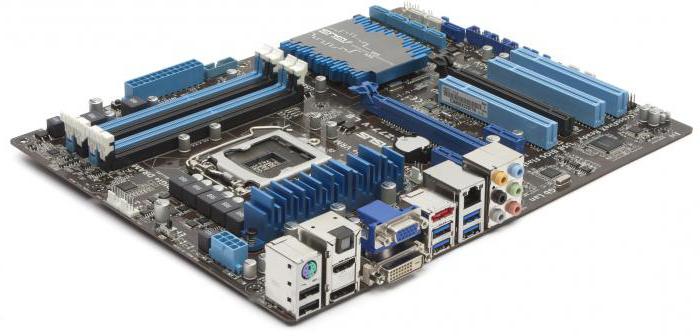
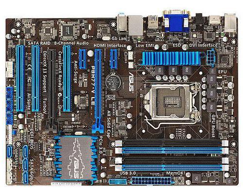
В формфакторе АТХ выполнена материнская плата ASUS P8H77-V LE. Ее размеры равны 305 мм в высоту и 226 мм в ширину. Практически посередине верхней половины системной платы находится уже привычный процессорный разъем для установки центрального процессорного устройства. Справа от него расположились слоты оперативной памяти, а еще ближе к краю платы — главный разъем питания.
В свою очередь, слева сгруппирована система электроснабжения центрального процессора, которая спрятана за пассивной системой теплоотвода, а за ним — интегрированные порты, которые после сборки ПК будут выведены на тыльной стороне компьютера.
Под сокетом выведены слоты для установки дополнительных контроллеров. Справа от них находится южный мост, который закрыт алюминиевым радиатором. В самом низу платы сгруппированы разъемы подключения внешних портов USB, передней панели и накопителей.
Чипсет
Как было отмечено ранее, ASUS P8H77-V LE базируется на наборе микросхем H77. Он ориентирован на сборку ПК среднего уровня. Среди его технических параметров можно выделить следующее:
- Максимальное количество адресуемого ОЗУ равно 32 Гб.
- Слот для установки графического акселератора с поддержкой PCI Express 16Х версии 3.0.
- Тепловой пакет — 6,7 Вт.
- Технология производства кремниевого кристалла — 65 нм.
Также необходимо отметить, что этот чипсет, разработанный компанией «Интел», состоит всего из одной единственной микросхемы — южного моста, который обеспечивает взаимодействие ЦПУ и дополнительных контроллеров. Второй же компонент чипсета (который также называется северным мостом) перенесен в ЦПУ.
Сокет и поддерживаемые модификации центральных процессоров
Данная системная плата оснащена сокетом LGA 1155. В нее могут устанавливаться любые процессоры на основе архитектуры Core от «Интел» второго и третьего поколений. Но вот использование в сочетании с данным продуктом ЦПУ линеек Pentium и Celeron не предусмотрено. Для раскрытия потенциала этих полупроводниковых кристаллов будет достаточно наличия в составе ПК материнской платы на базе чипсета H61. Ну а в сочетании с чипами Core i7 или Core i5 с индексом «К» наиболее оптимально использовать уже Z77, который позволяет их разгонять путем увеличения множителя.
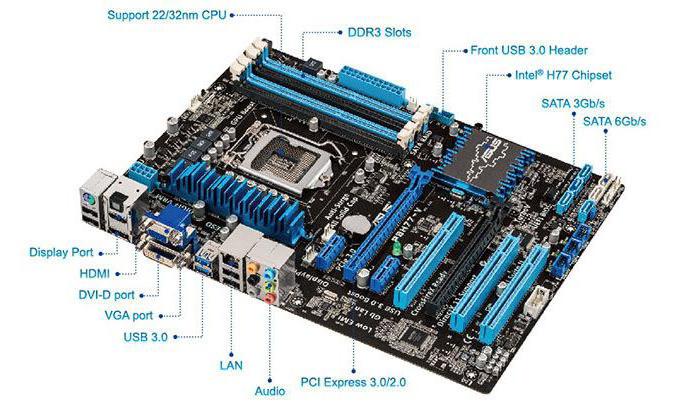
Порты и слоты
Плата ASUS P8H77 — V LE укомплектована следующими проводными портами:
- Комбинированный PS/2, в который может быть подключена как клавиатура, так и мышка.
- Четыре встроенных порта USB версии 2.0 и два встроенных порта USB модификации 3.0.
- Графических порта в этом случае три: привычные VGA и DVI дополнены новым продвинутым HDMI.
- Один встроенный порт для подключения к локальной вычислительной сети — LAN.
- 6 звуковых портов для создания различных акустических систем.
Также в данной плате есть такие слоты для установки внешних контроллеров:
- Для подключения дискретных графических акселераторов два PCI Express 16Х.
- Два слота формата PCI Express 1Х позволяют устанавливать дополнительные новые контроллеры расширения.
- Для установки устаревших контроллеров предусмотрено 3 слота PCI.
BIOS
ASUS P8H77-V LE может похвастаться наличием UEFI. Наличие такой подсистемы предзагрузки позволяет русифицировать меню и выполнить тонкую настройку компьютерной системы. Единственное, что нельзя в этом случае сделать, — увеличить множитель частоты ЦПУ. Но это ограничение обусловлено используемым в данной системной плате набором логики. При необходимости можно переключиться к привычной системе предзагрузки — BIOS, но, как показывает практика, проще и удобнее для конфигурирования ПК использовать именно UEFI.
Отзывы о продукте, его цена
Отличным решением для сборки ПК среднего уровня является ASUS P8H77-V LE. Обзор отзывов позволяет сделать вывод, что это действительно так. Компоновка платы тоже нареканий не вызывает. Все элементы разнесены по отдельным ее частям, и проблем с доступом к ним при переконфигурировании не должно возникнуть. Единственный минус в этом случае — не совсем удачная система крепления. Правая сторона платы частично висит в воздухе, и при установке или снятии компонентов с этого участка необходимо быть максимально осторожным. Купить такую плату пока еще можно. Ее ориентировочная стоимость — 100 долларов.

Итоги
ASUS P8H77-V LE хоть и является частично устаревшим решением, но позволяет собирать очень и очень производительные компьютеры. При этом стоимость существенно ниже, чем у более свежих продуктов на основе LGA 1150/LGA 1151. А вот разница в производительности между ними не настолько уж и существенна.
-
Страница 1
Motherboard P8H77-V[…]
-
Страница 2
ii G7024 Erste Ausgabe Juli 2012 Copyright © 2012 ASUST eK COMPUTER INC. A lle Rechte vorbehalten. Kein T eil dieses Handbuchs, einschließlich der darin beschriebenen Produkte und Software, darf ohne ausdrückliche, schriftliche Genehmigung von ASUST eK COMPUTER INC. (“ ASUS”) in irgendeiner F or m, ganz gleich auf welche Weise, vervielfälti[…]
-
Страница 3
iii Inhalt Sicherheitsinformationen ……………………………………………………………………………………… vi Über dieses Handbuch………………………………………………………………………………………….. vii P8H77-V Spezikationsübersicht ………………………………………..[…]
-
Страница 4
iv Inhalt Kapitel 3: BIOS-Setup 3.1 Kennenlernen des BIOS …………………………………………………………………………… 3-1 3.2 BIOS-Setupprogramm …………………………………………………………………………….. 3-1 3.2.1 EZ Mode ……………………………………………………………[…]
-
Страница 5
v 4.3.6 F AN Xper t ……………………………………………………………………………………………………… 4-9 4.3.7 Probe II ………………………………………………………………………………………………………… 4-10 4.3.8 Sensor Recorder ………………………………………[…]
-
Страница 6
vi Sicherheitsinforma tionen Elektrische Sicherheit • Um die Gefahr eines Stromschlags zu verhindern, ziehen Sie die Netzleitung aus der Steckdose, bevor Sie das System an einem ander en Or t aufstellen. • Beim Anschließen oder Trennen v on G eräten an das oder vom S ystem müssen die Netzleitungen der Geräte ausgesteckt sein, bevor die Sig […]
-
Страница 7
vii Über dieses Handbuch Di es es B enu tz er ha nd buc h en th äl t di e In fo rm a tio ne n, d ie Si e be i de r In st al la t i on u nd K on gu ra ti on d es Mo th er boa r d s br au ch en . Die Gestaltung dieses Handbuchs Das Handbuch enthält die folgenden T eile: • Kapitel 1: Produkteinführung Dieses Kapitel beschreibt die Leistungsm[…]
-
Страница 8
viii GEF AHR/W ARNUNG : Informationen zum V ermeiden von V erletzungen beim Ausführen einer A ufgabe. VORSICHT : Informationen zum Vermeiden von Schäden an den Komponenten beim Ausführ en einer Aufgabe . HINWEIS : Tipps und zusätzliche Informationen zur Erleichterung bei der Ausführung einer Auf gabe. WICHTIG : Anweisungen, die Sie beim A usf?[…]
-
Страница 9
ix P8H77- V Sp ezikationsübersicht CPU Intel® Sockel LGA1155 für 3./2. Gen Intel® C ore™ i7 / Core™ i5 / C ore TM i3 / Pentium ® / C eleron ® -Pr ozessoren Unterstützt Intel® Turbo Boost- T echnologie 2.0 Unterstützt 22/32nm-CPU Unterstützt Intel ® Turbo Boost T echnology 2.0 * Die U nterstü tzung f ür In tel ® T urbo Boo st- T[…]
-
Страница 10
x Audio VIA ® VT1708S 8-K anal HD-Audio- CODEC — Unterstützt Buchsenerkennung, Multi-Streaming und Frontblenden-Buchsenumprogrammierung — Optischer S/PDIF-Ausgang auf der Rücktafel USB Intel ® H77 Express Chipset — un terstüt zt ASUS USB 3.0 Boo st U ASP -Mod us* — 2 x USB 3.0/2.0-Anschlüsse auf Board-Mitte und Fr ontblende — 2 x U SB 3.0/2 .[…]
-
Страница 11
xi P8H77- V Sp ezikationsübersicht * Die Spezikationen können ohne Vorankündigung geändert werden. Rücktafelanschlüsse 1 x PS/2- T astatur-/Mausanschluss PS/2- T astatur-/Mausanschluss 1 x Optischer S/PDIF-Ausgang Optischer S/PDIF-Ausgang 1 x HDMI-Anschluss -Anschluss 1 x DVI-D-Anschluss -Anschluss 1 x D-Sub-Anschluss -Anschluss 1 x Dis[…]
-
Страница 12
xii[…]
-
Страница 13
ASUS P8H77-V 1-1 Kapitel 1 1.1 W illkommen! Vielen Dank für den Kauf eines ASUS ® P8H77-V-Motherboards! P8H77-V-Motherboards! Motherboards! Eine Vielzahl von neuen Funktionen und neuest en T echnologien sind in dieses Motherboard integriert und machen es zu einem weiteren hervorragenden Produkt in der langen Reihe der ASUS Qualitätsmotherboards![…]
-
Страница 14
1-2 Kapitel 1: Produkteinführung Kapitel 1 1.3 Sonder funktionen 1.3.1 Leistungsmerkmale des Produkts L GA1155-So ckel für Intel ® C ore™ i7 der 2. und 3. Generation / C ore™ i5 / Cor e™ i3- / P entium- / C eleron-Pr ozessoren Dieses Motherboard unterstützt die Intel ® 3./2. Generation Cor e™ i7/i5/i3/Pentium ® /Celeron ® -Pro zessor[…]
-
Страница 15
ASUS P8H77-V 1-3 Kapitel 1 Intel ® Rapid Start- T echnologie Damit können Sie Ihren Computer aus dem Niedrigleistungs-Ruhemodus in wenigen Sekunden ganz schnell wieder auf T ouren bringen. Der Speicher wird zu der zugewiesenen SSD gespeicher t und ermöglicht Ihren Computer somit, die Arbeit in kürzester Zeit wieder aufzunehmen, w ährend der En[…]
-
Страница 16
1-4 Kapitel 1: Produkteinführung Kapitel 1 EPU Energieezienz allgegenw ärtig Entdecken Sie den weltweit ersten Ech tzeit PC Energiespar chip durch die AI Suite II-An wendung. Erreichen Sie einheitliche, system weite Energieoptimierung durch die automatische Erkennung aktueller PC-Belastung sowie intelligente Regelung des Energ ieverbrauchs. Di[…]
-
Страница 17
ASUS P8H77-V 1-5 Kapitel 1 1.3.3 ASUS Quiet Thermische Lösung ASUS Quiet Thermische Lösung F anless Design: stilvolle Kühlk örper-Lösung -Lösung Der stilvolle Kühlkörper bietet eine 0dB-Kühlung für eine leise PC-Umgebung. Das moderne Design verbessert das Aussehen des Boards und des Gehäuses, während dur ch die hocheziente W ärmeabf[…]
-
Страница 18
1-6 Kapitel 1: Produkteinführung Kapitel 1 ASUS Q-Slot ASUS Q-Slot wurde entwickelt, um den Selbstbau-Prozess zu beschleunigen und zu v ereinfachen, damit Sie Ihre Heimwerkererfahrung verbessern können. 1.3.5 Sonstige Sonder funktionen LucidLogix V irtu MVP LucidLog ix Vir tu MVP mit der HyperFormance™- T echnologie steiger t die Leistung Ihrer[…]
-
Страница 19
ASUS P8H77-V 2-1 2.1 Bevor Sie beginnen Beachten Sie bitte vor dem I nstallieren der Motherboard-Komponenten oder dem Ändern von Motherboard-Einstellungen folgende Vorsichtsmaßnahmen. • Ziehen Sie das Netzkabel aus der Steckdose heraus, bevor Sie eine Komponente anfassen. • T ragen Sie vor dem Anfassen von Komponenten eine geerdete Manschette[…]
-
Страница 20
2-2 Kapitel 2: Hardwarebeschreibungen Kapitel 2 P8H77-V PCIEX16_1 PCIEX16_2 PCIEX1_2 PCIEX1_1 PCI1 PCI2 PCI3 USB56 USB78 USB910 USB3_34 PANEL SPDIF_OUT CHA_FAN1 CHA_FAN2 CPU_FAN Lithium Cell CMOS Power Super I/O VIA VT1708S DIGI +VRM AR 8161 COM1 64Mb BIOS SB_PWR CLRTC 22.6cm(8.9in) 30.5cm(12.0in) Intel ® H77 DDR3 DIMM_A1 (64bit, 240-pin module) D[…]
-
Страница 21
ASUS P8H77-V 2-3 Kapitel 2 Layout-Inhalt Anschlüsse/Jumper/Steckplätze Seite 1. CPU-, Gehäuse -, und Netzteillüfteranschlüsse (4-pol. CPU_F AN, 4-pol. CHA_F AN1/2, 3-pol. PWR_F AN) 2-23 2. A T X Netzanschlüsse (24-pol. EA T XPWR, 8-pol. EA TX12V ) 2-25 3. Intel ® L GA1155 CPU-S ockel 2-4 4. GPU Boost- T aste 2-17 5. GPU Boost LED 2-18 6. DDR[…]
-
Страница 22
2-4 Kapitel 2: Hardwarebeschreibungen Kapitel 2 2.2.2 Zentr alver arbeitungseinheit (CPU) Das Motherboard ist mit einem aufgelöteten L GA1155-S ockel für I ntel LGA1155-Sockel für Intel ® C o r e ™ i 7 / Core™ i5 / C ore™ i3- / P entium- / Celeron-Proz essoren der 2. & 3. Generation ausgestattet. P8H77-V P8H77-V CPU socket LGA1 155 ?[…]
-
Страница 23
ASUS P8H77-V 2-5 Kapitel 2 Empfohlene Speicherkongur ationen P8H77-V P8H77-V 240-pin DDR3 DIMM sockets DIMM_A1 DIMM_A2 DIMM_B1 DIMM_B2 2.2.3 Sy stemspeicher Das Motherboard ist mit vier Double Data R ate 3 (DDR3) Dual Inline Memor y M odule (DIMM)- Steckplätzen ausgestattet. Ein DDR3-Module sind anders geker bt als DDR- oder DDR2-M odule. Insta[…]
-
Страница 24
2-6 Kapitel 2: Hardwarebeschreibungen Kapitel 2 P8H77-V Motherboar d Liste qualizier ter Anbieter (Q VL) DDR3 2400 (O .C.) MHz Vendors Part No. Size SS/ DS Chip Brand Chip NO. Timing Voltage DIMM socket support (Optional) 1 DIMM 2 DIMM 4 DIMM Corsair CMGT X8(XMP) 8GB (2GBx 4) SS — — 10-12-10-27 1.65V • • • G.SKILL F3-19200CL11Q-16GBZHD(XMP[…]
-
Страница 25
ASUS P8H77-V 2-7 Kapitel 2 P8H77-V Motherboar d Liste qualizier ter Anbieter (Q VL) DDR3 2250 (O .C.) MHz Vendors Part No. Size SS/DS Chip Brand Chip NO. Timing Voltage DIMM socket support (Optional) 1 DIMM 2 DIMM 4 DIMM Kingston KHX2250C9D3T1K2/4GX( XMP) 4GB(2 x 2GB) DS — — — 1.65V • • • P8H77-V Motherboar d Liste qualizier ter Anbiete[…]
-
Страница 26
2-8 Kapitel 2: Hardwarebeschreibungen Kapitel 2 P8H77-V Motherboar d Liste qualizier ter Anbieter (Q VL) DDR3 1600 (O .C.) MHz Vendors Part No. Size SS/ DS Chip Brand Chip NO. Timing Voltage DIMM socket support (Optional) 1 DIMM 2 DIMM 4 DIMM A-DA T A AM2U16BC2P1 2GB SS A-DAT A 3CCD-1509A EL1126T — — • • • A-DA T A A X3U1600XB2G79-2X( XMP)[…]
-
Страница 27
ASUS P8H77-V 2-9 Kapitel 2 P8H77-V Motherboar d Liste qualizier ter Anbieter (Q VL) DDR3 1600 (O .C.) MHz (Fortsetzung) Vendors Part No. Size SS/ DS Chip Brand Chip NO. Timing Voltage DIMM socket suppor t (Optional) 1 DIMM 2 DIMM 4 DIMM Kingston KHX1600C7D3K2/4GX(XMP) 4GB(2 x 2GB) DS — — — 1.65V • • • Kingston KHX1600C8D3K2/4GX(XMP) 4GB(2 […]
-
Страница 28
2-10 Kapitel 2: Hardwarebeschreibungen Kapitel 2 P8H77-V Motherboar d Liste qualizier ter Anbieter (Q VL) DDR3 1333 (O .C.) MHz (Fortsetzung) Vendors Part No. Size SS/ DS Chip Brand Chip NO. Timing Voltage DIMM socket support (Optional) 1 DIMM 2 DIMM 4 DIMM Corsair CMD8GX3M4A1333C7 8GB(4 x 2GB) DS — — 7-7-7-20 1.60V • • • Crucial CT12864BA[…]
-
Страница 29
ASUS P8H77-V 2-11 Kapitel 2 P8H77-V Motherboar d Liste qualizier ter Anbieter (Q VL) DDR3 1333 (O .C.) MHz (Fortsetzung) Vendors P ar t No. Size SS/ DS Chip Brand Chip NO. Timing Voltage DIMM socket support (Optional) 1 DIMM 2 DIMM 4 DIMM Kingston KVR1333D3N9/4G-SP (low prole) 4GB DS Kingston D2568JENCPGD9U — 1.5V • • • Micron MT4JTF128[…]
-
Страница 30
2-12 Kapitel 2: Hardwarebeschreibungen Kapitel 2 P8H77-V Motherboar d Liste qualizier ter Anbieter (Q VL) DDR3 1066 (O .C.) MHz Seite(n): SS — Einseitig DS — Doppelseitig DIMM-Unterstützung: • 1 DI MM : Unte rstü tzt ein (1) Modul, das in ein er S ingle-Channe l-Speic herk ong uration in eine n be liebige n St eckplatz gestec kt wir d. Es[…]
-
Страница 31
ASUS P8H77-V 2-13 Kapitel 2 SP Nr . Steckplatzbeschreibung 1 PCIe 2.0 x1_1 slot 2 PCIe 3.0 x16_1-Steckplatz (im x16 Modus) 3 PCIe 2.0 x1_2-Steckplatz 4 PCI-Steckplatz 1 5 PCIe 2.0 x16_2 Steckplatz (im x4-Mo dus, mit PC Ie x1- und x4 -Geräte n komp atibel .) 6 PCI-Steckplatz 2 7 PCI-Steckplatz 3 VGA-K onguration PCI Express Betriebsmodus PCIe 3.[…]
-
Страница 32
2-14 Kapitel 2: Hardwarebeschreibungen Kapitel 2 • Um die beste Grakleistung zu erzielen, benutzen Sie bei der V er wendung einer einzelnen Grakkar te zuerst den PCIe 3.0/2.0 x16_1-Steckplatz (marineblau) für eine PCI Express x16- Grakkar te. • Wir empfehlen Ihnen, bei der Benutzung im CrossF ireX™-Modus eine ausreichende Stromv ers[…]
-
Страница 33
ASUS P8H77-V 2-15 Kapitel 2 2.2.5 Jumper RTC RAM löschen (3-pol. CLRT C) Mit diesem Jumper können Sie das Echtzeituhr- (RTC) R AM im CMOS löschen. Sie können d i e Ei n st e l l u n g d e s D a t u m s u n d d e r Z e i t s o w i e d i e Sy s t e m s e t u p — P a r a m e te r i m C M O S löschen, indem Sie die CMOS RTC RAM-Daten löschen. Die[…]
-
Страница 34
2-16 Kapitel 2: Hardwarebeschreibungen Kapitel 2 1. MemOK!- T aste Installieren von DIMMs, die nich t mit dem M otherboard kompatibel sind, k ann zu Boot-F ehlern führen und lässt die DRAM_LED in der Nähe der MemOK!- T aste dauer haft leuchten. Drücken und halten Sie die MemOK!- T aste, bis die DRAM_LED mit blinken beginnt, um d ie automatische[…]
-
Страница 35
ASUS P8H77-V 2-17 Kapitel 2 2. GPU Boost-Schalter Mit diesen Schalter können Sie die Funktion GPU Boost aktivieren/deaktivier en . P8H77-V P8H77-V GPU Boost switch GPU Boost 2.2.7 Onboard LEDs 1. Standby P ower LED Das Motherboard ist mit einer Standby Po wer LED (Bereitschaftsanzeige LED ) ausgestatt et die aueuchtet, wenn sich das System im e[…]
-
Страница 36
2-18 Kapitel 2: Hardwarebeschreibungen Kapitel 2 2. DRAM LED Die DRAM LED zeigt den DR AM-Status während des POST (Pow er-on Self T est) an. Falls ein Fehler gefunden wird, wird die DRAM-LED solange aufleuchten, bis der Fehler behoben wurde. Dieses benutzer freundliche Design bietet eine intiutive Lösung, Fehler in nur einer Sekunde zu lokalisier[…]
-
Страница 37
ASUS P8H77-V 2-19 Kapitel 2 2.2.8 Interne Anschlüsse 1. Intel ® H77 Serial A T A 6.0 Gb/s-Anschlüsse (7-pol. SA T A6G_1/2 [grau]) Diese Anschlüsse sind für Serial A T A 6.0Gb/s-Signalkabel der Serial A T A 6.0 Gb/s- Festpla tten vorgesehen. W enn Sie SA T A-F estpla tten instal liere n, könne n Sie mit der Intel ® Rapid Stor age- T echno log[…]
-
Страница 38
2-20 Kapitel 2: Hardwarebeschreibungen Kapitel 2 2. Intel ® H77 Serial A T A 3.0 Gb/s-Anschlüsse (7-pol. SA T A3G_1–4 [blau]) Diese Anschlüsse sind für Serial A T A 3.0Gb/s-Signalkabel der Serial A T A 3.0 Gb/s-Festpla tten und optischen Laufwerken vorgesehen. W enn Sie SA T A-F estpla tten instal liere n, könne n Sie mit der Intel ® Rapid […]
-
Страница 39
ASUS P8H77-V 2-21 Kapitel 2 3. USB 3.0 connector (20-1 pin USB3_34) Dieser Anschluss ist für zusätzliche USB 3.0-P orts vorgesehen und entspricht der USB 3.0- Spezikaton, die V erbindungsgeschwindigkeiten von bis 480 MBps zulässt. F alls ein USB 3.0-Fr onttafelk abel bei Ihrem Systemgehäuse vorhanden ist, können Sie mit diesem USB 3.0-Ansch[…]
-
Страница 40
2-22 Kapitel 2: Hardwarebeschreibungen Kapitel 2 5. Digitaler Audioanschluss (4-1 pol. SPDIF_OUT) Dieser Anschluss ist für zusätzliche Sony/Philips Digital Interface (S/PDIF)-M odul(e) vorgesehen. Verbinden Sie das S/PDIF-Ausgangsmodulkabel mit diesen Anschluss und installieren Sie das Modul anschließend an einer Steck platzaussparung an der Rü[…]
-
Страница 41
ASUS P8H77-V 2-23 Kapitel 2 7. CPU-, Gehäuse — und Netzteillüfteranschlüsse (4-pol. CPU_F AN, 4-pol. CHA_F AN1/2, 3-pol. PWR_F AN) V erbinden Sie die Lüfterkabel mit den Lüfteranschlüssen am Motherboard, wobei der schwarze Leiter jedes Kabels zum Erdungsstift des Anschlusses passen muss. • Der Anschluss CPU_F AN arbeitet mit einem CPU-Lüft[…]
-
Страница 42
2-24 Kapitel 2: Hardwarebeschreibungen Kapitel 2 8. Fron ttafelaudioanschluss (10-1 pol. AAFP) Dieser A nschluss dien t zum Verbinden eines F ronttafel-Audio E/A-Moduls, das an am G ehäuse des Computers befestigt wird und entweder HD Audio oder den herkömmlichen AC ‘97 Audiostandard unterstützt. Verbinden Sie das Ende des Fronttafel- Audiokabe[…]
-
Страница 43
ASUS P8H77-V 2-25 Kapitel 2 9. A T X-Stromanschlüsse (24-pol . EA T XPWR; 8-pol. EA TX12V ) Diese Anschlüsse sind für die A T X-Strom versorgungsstecker vorgesehen. Sie sind so aufgebaut, dass sie mit den Steckern in nur einer Richtung zusammenzupassen. Drücken Sie den Stecker in der korrekten A usrichtung fest auf den Anschluss, bis er komplet[…]
-
Страница 44
2-26 Kapitel 2: Hardwarebeschreibungen Kapitel 2 • Systemstr om-LED (2-p ol. PLED) Dies er 2-pol . Ansc hlu ss wird mit der Syst emstr om-LED verb unden. V erbinde n Sie das Str om-LED- Kabel vom Computergehäuse mit diesem Anschluss. Die Systemstr om-LED leuchtet, wenn Sie das System einschalten. Sie blinkt, w enn sich das System im Energiesparm[…]
-
Страница 45
ASUS P8H77-V 2-27 Kapitel 2 2.3 Aufbau des C omputersystems 2.3.1 Zusatzw erkzeug und K omponenten für den PC-A ufbau 1 T üte mit Schrauben Philips (Kr euz)-S chraubenzieher PC-Gehäuse Netzteil Intel L GA 1155 CPU Intel L GA 1155-kompatibler CPU-Lüfter DIMM SA T A-F estplatte Optisches SA T A-Laufwerk (wahlw eise) Grakkarte (wahlweise) Das W[…]
-
Страница 46
2-28 Kapitel 2: Hardwarebeschreibungen Kapitel 2 1 2 3 A B 2.3.2 Installieren der CPU Die LGA1156 CPU ist nicht mit LGA1155-Sockeln kompatibel. Installieren Sie KEINE LGA1156 CPU in den L GA1155-Sockel.[…]
-
Страница 47
ASUS P8H77-V 2-29 Kapitel 2 5 4 A B C[…]
-
Страница 48
2-30 Kapitel 2: Hardwarebeschreibungen Kapitel 2 2 B B A A 1 3 4 2.3.3 Installieren von CPU-K ühlkörper und Lüfter F alls erforderlich, bringen Sie die W ärmele itp ast e auf den CPU -Kü hlkörpe r und die CPU an, bevor Sie den CPU- Kühlkörper und Lüfter montieren. So installieren Sie den CPU-Kühlk örper und -Lüf ter:[…]
-
Страница 49
ASUS P8H77-V 2-31 Kapitel 2 2 A B B A 1 So deinstallieren Sie den CPU-Kühlk örper und -Lüf ter:[…]
-
Страница 50
2-32 Kapitel 2: Hardwarebeschreibungen Kapitel 2 1 2 3 Entfernen eines DIMMs 2.3.4 Installieren eines DIMMs B A A[…]
-
Страница 51
ASUS P8H77-V 2-33 Kapitel 2 2.3.5 Motherboard-Installation 2 1 Die Abbidlungen in diesem Abschnitt werden nur als Referenz bereitgestellt. Das M otherboard- Layout kann sich je nach Modell unterscheiden, der Installationsvorgang bleibt aber gleich.[…]
-
Страница 52
2-34 Kapitel 2: Hardwarebeschreibungen Kapitel 2 Ziehen Sie die Schrauben nicht zu fest! Das Motherboard könnte sonst beschädigt w erden. 3 P8H77-V[…]
-
Страница 53
ASUS P8H77-V 2-35 Kapitel 2 2.3.6 A TX-Netzanschlüsse 1 2 ODER ODER[…]
-
Страница 54
2-36 Kapitel 2: Hardwarebeschreibungen Kapitel 2 2.3.7 SA T A-Gerätanschlüsse 2 ODER 1[…]
-
Страница 55
ASUS P8H77-V 2-37 Kapitel 2 2.3.8 E/A-Anschlüsse auf der F orderseite So installieren Sie den Sy stemtafelanschluss USB 2.0 AAFP USB 2.0-Anschluss Fr onttafelaudioanschluss USB 3.0 USB 3.0-Anschluss[…]
-
Страница 56
2-38 Kapitel 2: Hardwarebeschreibungen Kapitel 2 2.3.9 Erweiterungskarten PCIe x16-Karten PCIe x1-Karten PCI-Karten[…]
-
Страница 57
ASUS P8H77-V 2-39 Kapitel 2 2.3.10 Rücktafelanschlüsse Rücktafelanschlüsse 1. PS/2- T astatur-/Maus-Kombianschluss 7. DisplayP or t 2. Optischer S/PDIF-A usgang 8. DVI-D-Anschluss 3. D-Sub-Anschluss 9. USB 3.0-Anschlüsse 1 und 2 (ASUS USB3.0 Boost T urbo M ode) 4. A theros ® LAN (RJ-45) -Anschluss** 5. USB 2.0-Anschlüsse 3 und 4 10. USB 2.0-[…]
-
Страница 58
2-40 Kapitel 2: Hardwarebeschreibungen Kapitel 2 *** Audio 2, 4, 6, oder 8-Kanalk ongurationen Anschluss Headset 2-Kanal 4-Kanal 6-Kanal 8-Kanal Hellblau Line In Line In Line I n Line In Hellgrün Line Out Frontlautspr echer Frontlautsprecher Fron tlautsprecher Rosa M ic In Mic In Mic In Mic In Orange – – Mitte/Subwoofer Mitte/Subwoofer Schw[…]
-
Страница 59
ASUS P8H77-V 2-41 Kapitel 2 Anschluss eines Kopfhör ers und M ikrofons Anschluss von S tereo Lautsprechern Anschluss von 2.1-Kanal Lautspr echern 2.3.11 Audio E/A- Ver bindungen Audio E/A- Anschlüsse[…]
-
Страница 60
2-42 Kapitel 2: Hardwarebeschreibungen Kapitel 2 Anschluss von 4.1-Kanal Lautsprechern Anschluss von 5.1-Kanal Lautsprechern Anschluss von 7.1-Kanal Lautsprechern[…]
-
Страница 61
ASUS P8H77-V 2-43 Kapitel 2 2.4 Erstmaliges Starten 1. Bringen Sie nach V ervollständ igen aller Anschlüsse die Abdeckung des Systemgeh äuses wieder an. 2. Stellen Sie sicher , dass alle Schalter im ausgeschalteten Zustand sind. 3. V er binden Sie das Netzkabel mit dem Netzanschluss an der Rückseite des Systemgehäuses. 4. Ve rbi nd en Sie das […]
-
Страница 62
2-44 Kapitel 2: Hardwarebeschreibungen Kapitel 2[…]
-
Страница 63
ASUS P8H77-V 3-1 Kapitel 3 Chapter 3: BIOS setup Kapitel 3 3.1 Kennenlernen des BIOS Das UEFI BIOS von ASUS ist eine Schnittstelle, die mit exibler und bequemer Maussteuerung die bisherige tastaturgebundene BIOS-Kontrolle ersetzt. Sie können sich kinderleicht und mit einer Sanftheit durch das neue UEFI BIOS bewegen, die bisher nur Betriebssyste[…]
-
Страница 64
3-2 Kapitel 3: BIOS-Setup Kapitel 3 BIOS-Setupprogramm ohne Speichern der Änderungen verlassen, Änderungen speichern und das System zurücksetz en oder zum Erweiterten Modus gehen Anzeigesprache des BIOS- Setupprogramms Zeigt CPU-/Motherboard- T emperatur , CPU/5V/3.3V/12V-Spannungs(ausgabe), CPU-/Gehäuse-/Netzteillüf tergeschwindigk eit Energi[…]
-
Страница 65
ASUS P8H77-V 3-3 Kapitel 3 Main Ai T weaker Advanced Monitor Boot T ool Exit Version 2.10.1208. Copyright ( C) 2011 American Megatrends, Inc. Atheros Lan HELP →← : Select Screen ↑↓ : Select Item Enter: Select +/-: Change Opt. F1: General Help F2: Previous V alues F5: Optimized Defaults F10: Save ESC: Exit F12: Print Screen Back Advanced On[…]
-
Страница 66
3-4 Kapitel 3: BIOS-Setup Kapitel 3 Menüelemente W enn ein Element auf der Menüleiste markier t ist, werden die speziellen Elemente für dieses Menü angezeigt. Wenn Sie z.B. Main gewählt haben, w erden die Elemente des Main-Menüs angezeigt. Die anderen Elemente (A i Tweaker , Advanced, Monitor , Boot, T ools und Exit) auf der Menüleiste haben[…]
-
Страница 67
ASUS P8H77-V 3-5 Kapitel 3 Main Ai T weaker Advanced Monitor Boot Tool Exit T o clear the administrator password, key in the current password in the Enter Current Passwor d box, and then press <Enter> when prompted to create/conrm the password. Password Description If ONLY the Administrator’s password is set, then this only limits acc[…]
-
Страница 68
3-6 Kapitel 3: BIOS-Setup Kapitel 3 Administra tor Passwor d F alls Sie ein Administrator-Kennw ort eingerichtet haben, sollten Sie für den vollen Systemzugri das Kennwort eingeben. Andernfalls lässt Sie das BIOS-Setupprogramm nur bestimmte Elemente einsehen bzw. ändern. So richten Sie ein Administrator -Kennwort ein: 1. W ählen Sie das Elem[…]
-
Страница 69
ASUS P8H77-V 3-7 Kapitel 3 Main Ai T weaker Advanced Monitor Boot Tool Exit Version 2.10.1208. Copyright ( C) 2011 American Megatrends, Inc. [X.M.P .] When XMP is enabled BL CK frequency, CPU ratio and memory parameters will be auto optimized. →← : Select Screen ↑↓ : Select Item Enter: Select +/-: Change Opt. F1: General Help F2: Previous V[…]
-
Страница 70
3-8 Kapitel 3: BIOS-Setup Kapitel 3 Ai Overclock T uner [Auto] Hier können Sie die CPU-Über taktungsoptionen auswählen, um eine gewünschte interne CPU- Fr equenz zu bestimmen. Wählen Sie eine der voreingestellt en Über taktungskongurationsoptionen aus. [Auto ] Lädt automatisch die optimalen Systemeinstellungen. [Manual] Lässt Sie die Par[…]
-
Страница 71
ASUS P8H77-V 3-9 Kapitel 3 Enhanced Intel SpeedStep T echnology [Enabled] Er mögl ich t A kti vier ung /De ak tiv ieru ng der Enh anc ed Int el ® Spe ed Ste p- T ech nol og ie (EI ST). [Disabled] Deaktiviert diese Funktion. [Enabled] Das Betriebssystem kann die Prozessorspannung und -kernfrequenz dynamisch anpassen, was zu niedrigeren Gesamtenerg[…]
-
Страница 72
3-10 Kapitel 3: BIOS-Setup Kapitel 3 DIGI+ VRM CPU Load-Line Calibr ation [Auto ] Load-line ist in den Intel VRM-Spezik ationen enthalten und beeinusst die CPU-Spannung. Die Betriebsspannung der CPU wird proportional zur Betriebslast der CPU abnehmen. Höhere Kalibrierung von load-line könnte die Spannung erhöhen und gute Übertaktungsleist[…]
-
Страница 73
ASUS P8H77-V 3-11 Kapitel 3 iGPU Load-line Calibr ation [Auto ] Erlaubt die Auswahl der iGPU Load-Line-Kalibrierung. Ko ng ur ati ons opt io nen : [Auto ] [Regular] [High] [Extreme] : [Auto ] [Regular] [High] [Extreme] iGPU Curr ent Capability [100%] Erlaubt die Auswahl von iGPU C urrent Capability . Ko ng ur ati ons opt io nen : [100%] [110%[…]
-
Страница 74
3-12 Kapitel 3: BIOS-Setup Kapitel 3 VC CIO V oltage [Auto ] Erlaubt die Einstellung der VCCIO-Spannung. Die W erte liegen z wischen 0.7350V und 1.6850V , einstellbar in 0.005V-Schritten. PCH V oltage [A uto] Erlaubt die Einstellung der Platform Con troller Hub-Spannung. Die Werte liegen zwischen 0.7350V und 1.6850V , einstellbar in 0.005V-Schritte[…]
-
Страница 75
ASUS P8H77-V 3-13 Kapitel 3 Beim Einstellen der Elemente im Advanced-Menü ist Vorsicht geboten. F alsche Werte können zu einer Systemfunktionsstörung führ en. 3.5 Advanc ed-M enü Die Elemente im Advanc ed-Menü gestatten Ihnen, die Einstellung für den Pro zessor und andere Systemgerät e zu ändern. Main Ai T weaker Advanced Monitor Boot T oo[…]
-
Страница 76
3-14 Kapitel 3: BIOS-Setup Kapitel 3 3.5.1 CPU Congur ation CPU Congur ation Die Werte in diesem Menü zeigen die vom BIOS automatisch erkannten CPU-bezogene Informationen an. Die hier gezeigten Elemente sind abhängig v om installierten Prozessor . Scrollen Sie nach unten, um auch die anderen Element e anzuzeigen: Main Ai T weaker Advanced M[…]
-
Страница 77
ASUS P8H77-V 3-15 Kapitel 3 Limit CPUID Maximum [Disabled] [Enabled] Ermöglicht älteren Betriebssystemen auch ohne Unt erstützung für CPUs mit erweiter ten CPUID-Funktionen zu boot en. [Disabled] D eaktiviert diese Funktion. Execut e Disable Bit [Enabled] [Enabled] Aktivier t die No-Execution Page P rotection- T echnologie. [Disabled] Zwingt de[…]
-
Страница 78
3-16 Kapitel 3: BIOS-Setup Kapitel 3 CPU C3 Repor t [Aut o] Erla ubt die Aktiv ierung oder De aktivi erun g des CPU C3 -Ber ich ts an das Betrieb ssyste m. Kongurationsoptionen: [A uto] [Enabled] [Disabled] : [Auto ] [Enabled] [Disabled] CPU C6 Repor t [Aut o] Erla ubt die Aktiv ierung oder De aktivi erun g des CPU C6 -Ber ich ts an das Betrieb […]
-
Страница 79
ASUS P8H77-V 3-17 Kapitel 3 3.5.3 SA T A Congura tion Das BIOS e rken nt aut omatis ch die vo rhanden en SA T A-Gerä te, w enn S ie das BIOS-Se tupp rogr amm aufr ufen. Die BI OS-Elem ente für die SA T A-A nsc hlü sse zeigen Not P resen t an, wenn i n dem ent spr echend en Ans chlu ss kei n S A T A-Gerät in sta llie r t is t. Main Ai T weake[…]
-
Страница 80
3-18 Kapitel 3: BIOS-Setup Kapitel 3 3.5.4 Sy stem Agent Congur ation Memory Remap Feature [Enabled] [Enabled] Hier können Sie den Speicher über 4GB neu einr ichten. [Disabled] D eaktiviert diese Funktion. Graphics C onguration Primary Display [Auto] Hier können Sie auswählen ob iGPU oder PCIE für die primäre Anzeige verwendet werden so[…]
-
Страница 81
ASUS P8H77-V 3-19 Kapitel 3 3.5.5 USB Congur ation Die Elemente in diesem Menü gestatten Ihnen, die USB-verwandten F unktionen einzustellen. Das Element USB Devices zeigt die automa tisch ermittelten Werte an. None wird angezeigt, wenn kein USB-Gerät erkannt wurde. Legacy USB Suppor t [Enabled] [Enabled] Aktivier t die Unterstützung für USB-[…]
-
Страница 82
3-20 Kapitel 3: BIOS-Setup Kapitel 3 3.5.6 Onboard Devices C onguration Main Ai T weaker Advanced Monitor Boot T ool Exit Version 2.10.1208. Copyright ( C) 2011 American Megatrends, Inc. Enabled/Disabled Azalia HD Audio →← : Select Screen ↑↓ : Select Item Enter: Select +/-: Change Opt. F1: General Help F2: Previous V alues F5: Optimized […]
-
Страница 83
ASUS P8H77-V 3-21 Kapitel 3 Serial Port Congur ation Das Untermenü in diesen menü ermöglicht Ihnen die Konguration des seriellen Anschlusses zu kongurieren. Dieses Element funktioniert nur, w enn auf dem M otherboard ein serieller (COM) — Anschluss vorhanden ist. Serial Port [Enabled] Hier können Sie den seriellen (COM) -Anschluss akti[…]
-
Страница 84
3-22 Kapitel 3: BIOS-Setup Kapitel 3 Po wer On By PCIE/PCI [Disabled] [Disabled] D eaktiviert PCIE/PCI- Geräteaufweckfunktion von Intel/Realtek LAN-Geräten. [Enabled] Aktiviert PCIE/PCI-Geräteaufweckfunktion von Intel/Realtek LAN-Geräten. Po wer On By Ring [Disabled] [Disabled] Deaktiviert die Funktion serieller Geräte, ein A ufweckereignis zu[…]
-
Страница 85
ASUS P8H77-V 3-23 Kapitel 3 3.6 Monitor menu Das Monitor-Menü zeigt die Systemt emperatur/den Energiestatus an und erlaubt die Anpassung der Lüftereinstellungen. Scrollen Sie nach unten, um auch die anderen Element e anzuzeigen: Version 2.10.1208. Copyright ( C) 2011 American Megatrends, Inc. 5V V oltage +5.080 V 12V V oltage +12.192 V Anti Surge[…]
-
Страница 86
3-24 Kapitel 3: BIOS-Setup Kapitel 3 Igno re fa lls die erka nnt en Lü fterdr ehzahl en nic ht angeze igt we rden sol len. CPU Q-F an Con trol [Enabled] [Disabled] D eaktiviert die CPU Q -F an-Kontrollfunktion. [Enabled] Aktivier t die CPU Q-Fan-Kontr ollfunktion. CPU F an Speed Low Limit [600 RPM] Dieses Element erscheint nur , wenn Sie die F unk[…]
-
Страница 87
ASUS P8H77-V 3-25 Kapitel 3 Chassis F an Profile [Standard] Di ese s Ele men t ers ch ein t n ur , wen n C hass is Q-F an Co ntr ol akt ivi ert w urd e u nd Ihne n d ie Mö gl ich keit gi bt, ei nen e nts pre che nden L eist ung spe gel für de n Ge häu sel üft er ein zus tel len. [Standard] Auf [Standard] setzen, um den Gehäuselüfter automatis[…]
-
Страница 88
3-26 Kapitel 3: BIOS-Setup Kapitel 3 3.7 Boot menu Die Elemente im Boot-Menü gestatten Ihnen, die Systemstartoptionen zu ändern. Bootup NumLock State [ On] [On] Setzt den Startstatus von NumLock auf [On]. [O ] S etzt den Startstatus von NumLock auf [O ]. F ull Screen Logo [Enabled] [Enabled] Aktivier t die Anzeigefunktion für das Vollbildl[…]
-
Страница 89
ASUS P8H77-V 3-27 Kapitel 3 Option ROM Messages [For ce BIOS] [For ce BIOS] Die ROM-M eldungen dritter Parteien werden w ährend des Boot-V organgs zwangsweise angezeigt. [Keep Current] Die ROM-Meldungen dritter Parteien werden während des Boot- Vorgangs nur angezeigt, wenn dies vom Herst eller speziell vorgesehen wurde. Setup Mode [EZ Mode] [A dv[…]
-
Страница 90
3-28 Kapitel 3: BIOS-Setup Kapitel 3 3.8 Tools menu Die Elemente im T ools-Menü gestatten Ihnen, die Einstellungen für besondere F unktionen zu verändern. Wählen Sie das gewünschte Element aus und drücken Sie anschließend die <Eingabetaste>, um das Untermenü anzeigen zu lassen. Main Ai T weaker Advanced Monitor Boot Tool Exit Be used […]
-
Страница 91
ASUS P8H77-V 3-29 Kapitel 3 • Das System darf während der Aktualisierung des BIOS NICHT ausgeschaltet oder neu gestartet werden! Ein Systemstartfehler kann die Folge sein! • Nur empfohlen, um die BIOS-Datei zu aktualisieren, die v on der gleichen Speicher/CPU- Konguration und BIOS-V ersion stammt. Label Hier können Sie die Beschriftung des[…]
-
Страница 92
3-30 Kapitel 3: BIOS-Setup Kapitel 3 3.9 Exit menu Die Elemente im Exit-Menü gestatten Ihnen, die optimalen Standardw erte für die BIOS-Elemente zu laden, sowie Ihre Einstellungsänderungen zu speichern oder zu verwerfen. Im Exit-Menü können Sie auch EZ Mode aufrufen. Load Optimized Defaults Diese Option belegt jeden einzelnen P arameter in den[…]
-
Страница 93
ASUS P8H77-V 3-31 Kapitel 3 3.10 Aktualisieren des BIOS Die ASUS-W ebseite veröentlicht die neusten BIOS- V ersionen, um Verbesserungen der Systemstabilität, der Kompatibilitä t oder der Leistung zur Verfügung zu stellen. Trotz dem ist die Aktualisierung des BIOS ein potentielles Risiko. Wenn mit der derzeitigen BIOS- V ersion keine Probleme[…]
-
Страница 94
3-32 Kapitel 3: BIOS-Setup Kapitel 3 BIOS über das Internet aktualisieren So können Sie das BIOS über das Internet aktualisieren: 1. W ählen Sie in der Liste der Optionen Update BIOS from Internet (BIOS über das Internet aktualisieren) und drücken Sie auf Next (Weiter) . 2. W ählen Sie den I hnen am nächsten gelegenen ASUS FTP-Ort aus, um s[…]
-
Страница 95
ASUS P8H77-V 3-33 Kapitel 3 • Die hier bereitgestellten Abbildungen sind nur als eine Ref erenz anzusehen. Die tatsächlichen BIOS-Informationen variieren mit Modellen. • Beziehen Sie sich auf das Software -Handbuch auf der Support-DVD oder besuchen Sie für detaillierte Soft ware-Konguration die ASUS-Webseite un ter www.asus.c om. BIOS übe[…]
-
Страница 96
3-34 Kapitel 3: BIOS-Setup Kapitel 3 Flash Info MODEL: P8H77-V VER: 0303 DATE: 12/21/2011 Exit [Enter] Select or Load [Tab] Switch [Up/Down/P ageUp/PageDown/Home/End] Move [Esc] Exit [F2] Backup fs0: Drive Folder Info fs0: 11/08/11 10:23p 4194304 P8H77V.CAP fs1: ASUS EZ Flash 2 Utility v01.04 File Infor MODEL: VER: DA TE: Help Info 3.10.2 ASUS E[…]
-
Страница 97
ASUS P8H77-V 3-35 Kapitel 3 3.10.3 ASUS CrashFr ee BIOS 3 ASUS CrashF ree BIOS 3 ist ein Auto-W iederherstellungs-Dienstprogramm, das Ihnen erlaubt, die BIOS-Datei wiederherzustellen, falls sie versagt oder während des Aktualisierungsv organgs beschädigt wurde. Sie können eine beschädigte BIOS-Dat ei über die Motherboard Support-DVD oder einen[…]
-
Страница 98
3-36 Kapitel 3: BIOS-Setup Kapitel 3 Welcome to FreeDOS (http://www.freedos.org)! C:>d: D:> Please select boot device: SAT A: XXXXXXX XXX XXXX XX USB XXXXXX XXXX XXXXXXX UEFI: XXXXXX XXXX XXXXXX Enter Setup ↑ and ↓ to move selection ENTER to selec t boot device ESC to boot using defaults Das Sy stem im DOS -Modus hochfahren 1. Steck[…]
-
Страница 99
ASUS P8H77-V 3-37 Kapitel 3 ASUSTek BIOS Updater for DOS V1.28 Current ROM Update ROM A: Note [Enter] Select or Load [Tab] Switch [V] Drive Info [Up/Down/Home/End] Move [B] Backup [Esc] Exit P8H77V.CAP 4194304 2011-11-08 17:30:48 PATH: A: BOARD: P8H77-V VER: 0303 DATE: 12/21/2011 BOARD: Unknown VER: Unknown DATE: Unknown D:>bupdater /pc /g Are[…]
-
Страница 100
3-38 Kapitel 3: BIOS-Setup Kapitel 3[…]
-
Страница 101
ASUS P8H77-V 4-1 Kapitel 4 Chapter 4: Software support Wenn A utorun NICHT aktivier t ist, durchsuchen Sie den Inhalt der Support-DVD, um die Datei ASSETUP .EXE im BIN-Verzeichnis zu nden. Doppelklicken Sie auf ASSETUP .EXE, um die DVD auszuführen. 4.1 Installieren eines Betriebssystems Dieses Motherboard unterstützt Windows ® XP/ 64-Bit XP/ […]
-
Страница 102
4-2 Kapitel 4: Soft ware-Unterstützung Kapitel 4 4.2.2 Beziehen der Sof tware-Handbücher Die Software -Handbücher sind auf der Suppor t-DVD enthalten. F olgen Sie den Anweisungen, um die nötigen Handbücher zu erhalten. Die Dateien der Software-Handbücher liegen im PDF-Format vor . Installieren Sie Adobe ® Acrobat ® Reader vom Hilfsprogrammm[…]
-
Страница 103
ASUS P8H77-V 4-3 Kapitel 4 4.3 Sof tware informa tion Die meisten Anw endungen auf der Support-DVD besitzen Assistenten, die Sie in geeigneter W eise durch die Installation führen. Weiter e Informationen nden Sie in der Online-H ilfe oder den Readme -Dateien, die bei der Software enthalten sind. 4.3.1 AI Suite II ASUS AI Suite II ist eine kompl[…]
-
Страница 104
4-4 Kapitel 4: Soft ware-Unterstützung Kapitel 4 3. T urboV über taktet automatisch die CPU, speichert die BIOS-Einstellungen und startet das System neu. Nachdem Sie Windows wieder betr eten, informier t Sie eine Nachricht über den Erfolg von Auto T uning. Zum Verlassen auf OK klicken. Auto T urning verwenden 1. Klicken Sie auf Auto T uning im A[…]
-
Страница 105
ASUS P8H77-V 4-5 Kapitel 4 4.3.3 DIGI+ VRM ASUS DIGI+ VRM ermöglicht di e Anpa ssung der VRM-Spannu ng und F requenz-mod ulati on, um die Zuv erlässigkeit s owie Stabilität d es System s zu g ewährl eisten . Es bietet auch höchste Energ ieezienz un d erzeu gt w eniger Wärmer für längere Le bensdau er der Kompo nente n und minimal e Ener […]
-
Страница 106
4-6 Kapitel 4: Soft ware-Unterstützung Kapitel 4 Automatischer Tuning-Modus Manueller Modus Aktuelle Einstellungen als neues Prol speichern Spannungs- regler Alle Änderungen sofort übernehmen Alle Änderungen verwerfen 4.3.4 T urboV EVO ASUS TurboV EVO stellt T urboV vor , welches die manuelle Anpassung der CPU-F requenz und bezogener Spannun[…]
-
Страница 107
ASUS P8H77-V 4-7 Kapitel 4 Einstellregler Startlaufwerk Alle Änderungen verwerfen Standard-einstellungen laden Zielwerte Alle Änderungen sofort übernehmen Übertaktungseinstellungen speichern Advanc ed Mode (Erweiterten Modus) verwenden Klicken Sie auf Advanced Mode , um erweiterte Spannungseinstellungen vorzunehmen. GPU-Boost verwenden Klicken […]
-
Страница 108
4-8 Kapitel 4: Soft ware-Unterstützung Kapitel 4 4.3.5 EPU EPU ist eine energiesparende An wendung, die verschiedenen Betriebsanforderungen nachkommen kann. Diese Anwendung bietet mehrer e Betriebsmodi zur Auswahl, um Energiesparend zu arbeiten. Die A uswahl von Auto mode (Aut om. Modus) lässt das System automatisch, dem aktuellen Systemsta tus e[…]
-
Страница 109
ASUS P8H77-V 4-9 Kapitel 4 Für detaillierte Software-Kongurationen beziehen Sie sich bitte auf die Software -Handbücher auf der Support-DVD oder auf der ASUS-Webseite www .asus.com. 4.3.6 F AN Xper t F an Xper t ermöglicht es dem Benutzer , die Lüftergeschwindigkeit der CPU- und Gehäuselüfter je nach der Umgebung einzustellen, um den versc[…]
-
Страница 110
4-10 Kapitel 4: Soft ware-Unterstützung Kapitel 4 4.3.7 Probe II Das Prog ramm Pr obe II überwacht die wichtigsten Komponenten des Computers und inf ormiert Sie, falls Pr obleme entdeckt werden. Probe II erkennt un ter anderem die Lüfter drehzahlen, die CPU- T emperatur und Systemspannungen. Mit Hilfe dieses Pr ogramms wer den optimale Betriebsb[…]
-
Страница 111
ASUS P8H77-V 4-11 Kapitel 4 4.3.8 Sensor Recorder Änderungen bei Systemspannungen, T emperaturen und L üf tergeschwindigkeiten. Die V erlaufsfunktion ermöglicht Ihnen die Festlegung einer bestimm ten Zeitspanne für die Aufzeichnung , um für bestimmte Gründe eine Über wachung dieser drei Sy stemstati durchzuführ en. Sensor Recorder starten N[…]
-
Страница 112
4-12 Kapitel 4: Soft ware-Unterstützung Kapitel 4 4.3.9 USB 3.0 Boost Di e ex klu si ve A SU S U SB 3 .0 B oos t- F un kt io n bi et et e in e Ge sc hw in di gk ei ts st ei ge ru ng fü r US B 3. 0 -G er ät e un d ak tu el l e Un te rs tü tz un g de s US B A tt ach ed S CS I- P ro to ko ll s (U AS P) . Mit U SB 3 . 0 Bo os t kön ne n Si e d ie […]
-
Страница 113
ASUS P8H77-V 4-13 Kapitel 4 4.3.10 ASUS Update Mit ASUS Update haben Sie ein W er kzeug für die Aktualisierung des BIOS Ihres Systems . Aktualisieren Sie Ihr BIOS oder speichern Sie das Progr amm einfach für die spätere Benutzung. ASUS Update starten Nachdem Sie AI Suite II von der Motherboard Support-DVD installiert haben, star ten Sie ASUS Upd[…]
-
Страница 114
4-14 Kapitel 4: Soft ware-Unterstützung Kapitel 4 4.3.11 MyLogo2 Mit ASUS MyLogo können Sie das Boot-Logo anpassen. Das Boot-Logo ist das Bild , welches während des P ower-On Self-T ests (POST ) erscheint. Personizier en Sie I hren Computer gleich v on Anfang an! ASUS Update starten Nachdem Sie AI Suite II von der Motherboard Support-DVD inst[…]
-
Страница 115
ASUS P8H77-V 4-15 Kapitel 4 2. Klicken Sie auf Auto T une , um die Bildgröße oder Auösung zu kongurieren. 3. Sie können auf Booting Preview klicken, um eine Vorschau des Boot-Logos zu sehen. Klicken Sie dann auf Next . 4. Klicken Sie auf Flash , um die Aktualisierung des Boot-Logos mit den neuen Bild auszuführen. 5. Klicken Sie auf Y es […]
-
Страница 116
4-16 Kapitel 4: Soft ware-Unterstützung Kapitel 4 Für detaillierte Software-Kongurationen beziehen Sie sich bitte auf die Software -Handbücher auf der Support-DVD oder auf der ASUS-Webseite www .asus.com. 4.3.12 VIA® High-Denition-Audioprogramm Der VIA® High Denition Audio CODEC bietet 8-Kanal-Audio , um die ultimative Audioerfahrung […]
-
Страница 117
ASUS P8H77-V 4-17 Kapitel 4 4.4 RAID -Kongur ationen Dieses Motherboard unterstützt folgende SA T A RAID -Lösungen: • Intel ® Rapid Storage- T echnologie mit RAID 0, RAID 1, R AID 10 und RAID 5. • Sie müssen Windows ® XP Service Pack 3 oder eine neuer e V ersion installieren, bevor Sie Serial A T A-Festplatten benutz en können. Die S e[…]
-
Страница 118
4-18 Kapitel 4: Soft ware-Unterstützung Kapitel 4 Intel(R) Rapid Storage Technology — Option ROM — v10.5.1.1070 Copyright(C) 2003-10 Intel Corporation. All Rights Reserved. [ MAIN MENU ] 1. Create RAID Volume 4. Recovery Volume Options 2. Delete RAID Volume 5. Acceleration Options 3. Reset Disks to Non-RAID 6. Exit [ DISK/VOLUME INFORMATION ] RAID[…]
-
Страница 119
ASUS P8H77-V 4-19 Kapitel 4 Intel(R) Rapid Storage Technology — Option ROM — v10.5.1.1070 Copyright(C) 2003-10 Intel Corporation. All Rights Reserved. [ CREATE VOLUME MENU ] [ HELP ] Enter a unique volume name that has no special characters and is 16 characters or less. [ ↑↓ ]Change [TAB]-Next [ESC]-Previous Menu [ENTER]-Select Name: Volume0 RA[…]
-
Страница 120
4-20 Kapitel 4: Soft ware-Unterstützung Kapitel 4 WARNING: ALL DATA ON SELECTED DISKS WILL BE LOST. Are you sure you want to create this volume? (Y/N): 5. Benutzen Sie die Pfeiltasten auf/ab , um ein Laufwerk auszuwählen und drücken Sie zur Bestätigung dann auf die <Leertaste>. Ein kleines Dreieck mark iert das ausgewählte Laufwerk. Drü[…]
-
Страница 121
ASUS P8H77-V 4-21 Kapitel 4 Intel(R) Rapid Storage Technology — Option ROM — v10.5.1.1070 Copyright(C) 2003-10 Intel Corporation. All Rights Reserved. [ DELETE VOLUME MENU ] [ HELP ] Deleting a volume will reset the disks to non-RAID. WARNING: ALL DISK DATA WILL BE DELETED. (This does not apply to Recovery volumes) [ ↑↓ ]-Select [ESC]-Previous […]
-
Страница 122
4-22 Kapitel 4: Soft ware-Unterstützung Kapitel 4 4.4.5 Einführung in die Intel ® 2012 Desktop- Ansprechv erhaltentechnologien Dieses Dokument zeigt eine Übersicht der Installations- und Kongurationsvorgänge der Intel ® 2012 Desktop-Ansprechverhalten technologien. Die Intel ® 2012 Desktop-Ansprechverhalten technologien beinhalten die f ol[…]
-
Страница 123
ASUS P8H77-V 4-23 Kapitel 4 SSD-Kapazitätsanforderungen SSD-Partitionskapazitäts-an- forderungen Syst em-DR AM 2GB 4GB 8GB Intel ® -Datentr ägerkombinationen Intel ® Rapid Start 2GB 4GB 8GB Intel ® Smart Response 20GB 20GB 20GB Intel ® Smart Response und Intel ® Rapid Start Separate 20GB und 2GB- Partition (SSD-Größe > 22GB) Separate 2[…]
-
Страница 124
4-24 Kapitel 4: Soft ware-Unterstützung Kapitel 4 Intel ® Smart Response T echnology Intel ® Smart Response -T echnologie erhöht die Gesamtsystemleistung. Sie v er wendet eine schnelle SSD (mit min. 20GB frei) als ein Zwischenspeicher (C ache) für of t verwendete Proz esse, um den Austausch zwischen Festplatte/Hauptspeicher zu beschleunigen. H[…]
-
Страница 125
ASUS P8H77-V 4-25 Kapitel 4 3. Select Disable Accelera tion to disable this function, and select Change Mode to switch acceleration mode to Enhanc ed/Maximized. • Um lntel Um lntel ® Smart R esponse-T echnologie zu aktivieren, benötigen Sie eine SSD ( > = 20GB) und ein Festplatt enlaufwerk . Eine SSD kann nur einer einzelnen Festplatte zugew[…]
-
Страница 126
4-26 Kapitel 4: Soft ware-Unterstützung Kapitel 4 3. Rechtsklicken Sie auf Rechtsklicken Sie auf New V olume , welches Sie erstellen wollen und wählen Sie dann Shrink Volume . 4. F alls Ihre SSD nicht initialisier t und unformatiert ist: F alls I hre SSD nicht initialisiert und unformatiert ist: a. Rechtsklicken Sie auf die Disk die Sie für die […]
-
Страница 127
ASUS P8H77-V 4-27 Kapitel 4 6. Um das Disk-P ar titionsprogramm zu starten, klicken Sie bitte auf Um das Disk-P ar titionsprogramm zu starten, k licken Sie bitte auf Start > Alle Programme > Zubehör > Eingabeauorderung . 7. Tippen Sie Tippen Sie diskpart ein und drücken Sie auf die Eingabetaste . 8. In der Diskpar t-Eingabeauf- In der[…]
-
Страница 128
4-28 Kapitel 4: Soft ware-Unterstützung Kapitel 4 12. Tippen Sie Tippen Sie set id=84 override ein und drücken Sie auf die Eingabetaste . W arten Sie auf den V erkleinerungsvorgang bis das Datenträgerverwaltungsprogramm eine neue Partition mit den Namen Hibernation Partition gefunden hat. 13. Starten Sie das System neu, nachdem Sie die P ar titi[…]
-
Страница 129
ASUS P8H77-V 4-29 Kapitel 4 Diere Vorgang ermöglicht Ihnen, die Intel ® Rapid Start T echnology von Ihren System zu löschen und die für die Intel Rapid ® Star t T echnology erstellte Partition wiederherzustellen. F ühren Sie die Eingabeauorder ung aus. Tippen Sie diskpart ein und drücken Sie auf die Eingabetaste . In der Diskpar t-Eingabe[…]
-
Страница 130
4-30 Kapitel 4: Soft ware-Unterstützung Kapitel 4 5. Tippen Sie Tippen Sie list partition ein und drücken Sie dann auf die Eingabetaste . W ählen Sie nun die Partition in der Intel ® Rapid Star t T echnology installier t ist, indem Sie select partition x (x = Nummer), eintippen und anschließend auf die Eingabetaste drücken. 6. Tippen Sie Tipp[…]
-
Страница 131
ASUS P8H77-V 4-31 Kapitel 4 10. Klicken Sie auf Klicken Sie auf Next , nachdem Sie die standardmäßig ausgewählte Disk gewählt haben. 11. Die Einrichtung des erweiter ten Datenträgers ist abgeschlossen. Click Die Einrichtung des erweiter ten Datenträgers ist abgeschlossen. Click F inish to recover the Intel ® Rapid Star t T echnology par titi[…]
-
Страница 132
4-32 Kapitel 4: Soft ware-Unterstützung Kapitel 4 5. W ählen Sie alle aus und k licken W ählen Sie alle aus und klicken Sie auf Next , um Custom Setup auszuführen. 6. Klicken Sie auf Klicken Sie auf Install , um mit der Installation fortzufahren. 7. Klicken Sie auf Klicken Sie auf Y es , um I hr System neu zu starten, damit die Einstellungen de[…]
-
Страница 133
ASUS P8H77-V 4-33 Kapitel 4 3. Um die Aktualisierungs- Um die Aktualisierungs- funktion zu deaktivieren klicken Sie auf Disable Updating . Das Klicken auf diese Schaltäche deaktiviert automatisch die Konguration im T ab Advanced Um die Standardeinstellungen wiederherzustellen klicken Sie auf Reset All to Defaults . 4. Im T ab I m T ab Advanc[…]
-
Страница 134
4-34 Kapitel 4: Soft ware-Unterstützung Kapitel 4 4.5 Erstellen einer RAID- T reiberdiskette Eine Diskette mit dem RAID- Treiber ist erforderlich, wenn Sie Windows ® Betriebssysteme auf einem Laufwerk eines RAID-Sets installieren. • Das Motherboard bietet KEINEN Diskettenlaufw erksanschluss . Sie müssen ein USB- Diskettenlaufwerk benutzen, wen[…]
-
Страница 135
ASUS P8H77-V 4-35 Kapitel 4 4.5.3 Installieren des RAID- T reibers während der Window s ® -I nstallation So installieren Sie die RAID- T reiber für W indows ® XP 1. W ährend der Betriebssysteminstallation fordert das System Sie auf , die T aste <F6> zu drücken, um SCSI- oder RAID-T reiber von anderen Anbietern zu installieren. 2. Drück[…]
-
Страница 136
4-36 Kapitel 4: Soft ware-Unterstützung Kapitel 4 or 4.5.4 Benutzen eines USB-Diskettenlaufwerks Durch die Beschränkungen des Betriebssystems erkennt Windows ® XP das USB-Diskettenlaufwerk möglicherweise nicht, wenn Sie den RAID- T reiber während der Installation des Betriebssystems von einer Diskette installieren wollen. Um dieses Problem zu […]
-
Страница 137
ASUS P8H77-V 4-37 Kapitel 4 [HardwareIds.scsi.iaAHCI_DesktopWorkstationServer] id= “PCIVEN_8086&DEV_1C02&CC_0106”,”iaStor” id= “USBVID_03EE&PID_6901”, “usbstor” [HardwareIds.scsi.iaStor_DesktopWorkstationServer] id= “PCIVEN_8086&DEV_2822&CC_0104”,”iaStor” id= “USBVID_03EE&PID_6901”, “usbstor[…]
-
Страница 138
4-38 Kapitel 4: Soft ware-Unterstützung Kapitel 4[…]
-
Страница 139
ASUS P8H77-V 5-1 Chapter 5: Multiple GPU technology support Kapitel 5 5.1 A TI ® CrossF ireX™- T echnologie Dieses Motherboard unterstützt die A TI ® CrossFir eX™-T echnologie, mit der Sie mehrere GPU (Graphics proc essing unit) Grakkar ten installieren können. Folgen Sie den Installationsanweisungen in diesem Abschnitt. 5.1.1 Anforder u[…]
-
Страница 140
5-2 Kapitel 5: Unterstützung der Multi-GPU- T echnologie Kapitel 5 5. Schließen Sie zwei zusätzliche Stromv ersorgungsk abel vom Netzteil an jede der beiden Grakkar ten an. 6. Schließen Sie VGA- oder DVI-K abel an die Grakkar te an. 4. Richten Sie die CrossF ireX-Brücke mit den goldenen Anschlüssen aus und stecken Sie ihn darauf . V erg[…]
-
Страница 141
ASUS P8H77-V 5-3 Kapitel 5 1 2 3 4 5.1.4 Installieren der Gerätetr eib er Beziehen Sie sich auf die dem Grakk artenpaket beigefügten Anweisungen, um die Gerätetr eiber zu installieren. Ver gewisser n Sie sich, dass der PCI Express-Grakk artentreiber die A TI ® CrossFir eX™-T echnologie unterstützt. Laden Sie die neusten Tr eiber von de[…]
-
Страница 142
5-4 Kapitel 5: Unterstützung der Multi-GPU- T echnologie Kapitel 5 5.2 LucidLogix Virtu MVP Mit LucidLogix Virtu MVP k ann Ihr Computer unter Niedrigenergiebedingungen VGA-Ausgaben, und die Grakkar tenleistung verbessern, schneller reagieren und Mediendateien üssiger bearbeiten. Die GPU-Virtualisierung weist den besten verfügbaren Grakq[…]
-
Страница 143
ASUS P8H77-V 5-5 Kapitel 5 i-Mode Um LucidLog ix Vir tu MVP im i-Mode laufen zu lassen, muss das Anzeigegerät mit dem Videoausgang des Motherboards verbunden sein. Setzen Sie die primäre Anzeige im BIOS auf iGPU , um die i-M ode-Unterstützung zu aktivieren. d-Mode Um LucidLog ix Vir tu MVP im d-Mode laufen zu lassen, muss das Anzeigegerät mit d[…]
-
Страница 144
5-6 Kapitel 5: Unterstützung der Multi-GPU- T echnologie Kapitel 5 5.2.3 LucidLogix V irtu MVP kongurieren Starten Sie das V ir tu MVP Control Panel , um die Hauptfunktionen zu kongur ieren, Leistungseinstellungen vorzunehmen und An wendungen für die grasche V ir tualisierung auszuwählen. Rechtsklicken Sie auf das LucidLogix -Virtu-MVP-[…]
-
Страница 145
ASUS P8H77-V 5-7 Kapitel 5 Performance Hier können Sie die Funktionen Hyperformance ® oder Vir tual V sync ein- oder ausschalten. Hyperformance® ein- oder ausschalten Virtual V sync ein- oder ausschalten[…]
-
Страница 146
5-8 Kapitel 5: Unterstützung der Multi-GPU- T echnologie Kapitel 5 Beschreibung der drei Spalten: D: Hier können Sie die Anwendungen auswählen, die über die auf gesetzte Grakkar te laufen sollen. Wählen Sie D , um die 3D-Grak leistung für diese Anwendung zu aktivieren. I: Hier können Sie die Anwendungen auswählen, die über iGPU lauf […]
-
Страница 147
ASUS P8H77-V A-1 Anhang Anhang F ederal C ommunic ations C ommission Statement This device complies with P ar t 15 of the FCC Rules. Operation is subject to the f ollowing two conditions: • This device may not cause harmful interference . • This device must accept an y inter ference receiv ed including inter ference that may cause undesired ope[…]
-
Страница 148
A-2 Anhang Anhang VC CI: Japan Compliance Sta tement VC CI Class B Statement K C: Korea W arning Statement Canadian Department of Communications Sta tement This digital apparatus does not ex ceed the Class B limits for radio noise emissions from digital apparatus set out in the Radio Inter ference Regulations of the C anadian Department of Communic[…]
-
Страница 149
ASUS Kon taktinformationen ASUST eK COMPUTER INC. Adresse 15 Li- T e Road, Peitou, T aipei, T aiwan 11259 T elefon +886-2-2894-3447 F ax +886-2-2890-7798 E-Mail info@asus.com.tw W ebseite www.asus.c om.t w T echnische Unterstützung T elefon +86-21-38429911 Online-Suppor t support.asus.com ASUS C OMPUTER INTERNA TIONAL (Amerika) Adresse 800 Corpor […]
-
Страница 150
EC Declaration of Conformity We, the undersigned, Manufacturer: ASUSTek COMPUTER INC. Address, City: No. 150, LI-TE RD., PEITOU, TAIPEI 112, TAIWAN R.O.C. Country: TAIWAN Authorized representative in Europe: ASUS COMPUTER GmbH Address, City: HARKORT STR. 21-23, 40880 RATINGEN Country: GERMANY declare the following apparatus: Product name : Motherbo[…]
-
Page 1
P8H77-V… -
Page 2
Product warranty or service will not be extended if: (1) the product is repaired, modified or altered, unless such repair, modification of alteration is authorized in writing by ASUS; or (2) the serial number of the product is defaced or missing. -
Page 3: Table Of Contents
Contents Safety information …………………. vi About this guide ………………….vii P8H77-V specifications summary …………….ix Package contents ………………… xiii Chapter 1: Product introduction Special features ……………….. 1-1 1.1.1 Product highlights …………….1-1 1.1.2 ASUS DIGI+ VRM …………….1-3 1.1.3 ASUS Quiet Thermal Solution…………1-4 1.1.4…
-
Page 4
Managing and updating your BIOS …………. 2-1 2.1.1 ASUS Update utility ……………. 2-1 2.1.2 ASUS EZ Flash 2 …………….2-2 2.1.3 ASUS CrashFree BIOS 3 utility …………2-3 2.1.4 ASUS BIOS Updater …………… 2-4 BIOS setup program ………………2-6 Main menu ………………..2-10 2.3.1 System Language [English] ………… -
Page 5
2.7.8 Boot Option Priorities …………..2-29 2.7.9 Boot Override …………….2-29 Tools menu ………………..2-30 2.8.1 ASUS EZ Flash 2 Utility …………..2-30 2.8.2 ASUS O.C. Profile …………….. 2-30 2.8.3 ASUS SPD Information …………..2-30 Exit menu ………………..2-31 Appendices Notices …………………… -
Page 6: Safety Information
Safety information Electrical safety • To prevent electrical shock hazard, disconnect the power cable from the electrical outlet before relocating the system. • When adding or removing devices to or from the system, ensure that the power cables for the devices are unplugged before the signal cables are connected. If possible, disconnect all power cables from the existing system before you add a device.
-
Page 7: About This Guide
Refer to the following sources for additional information and for product and software updates. ASUS websites The ASUS website provides updated information on ASUS hardware and software products. Refer to the ASUS contact information. Optional documentation Your product package may include optional documentation, such as warranty flyers, that may have been added by your dealer.
-
Page 8: Conventions Used In This Guide
Conventions used in this guide To ensure that you perform certain tasks properly, take note of the following symbols used throughout this manual. DANGER/WARNING: Information to prevent injury to yourself when trying to complete a task. CAUTION: Information to prevent damage to the components when trying to complete a task IMPORTANT: Instructions that you MUST follow to complete a task.
-
Page 9: P8H77-V Specifications Summary
Due to the CPU behavior�� DDR3 2133/1866 MHz memory module will run at DDR3 2000/1800 MHz fre�uency as default. • Refer to Refer to www.asus.com for the latest Memory QVL (Qualified Vendors List). • When you install a total memory of 4GB capacity or more�� Windows When you install a total memory of 4GB capacity or more��…
-
Page 10
Windows ® ASUS DIGI+ VRM ASUS uni�ue features — ASUS DIGI+ VRM: Digital Power Design for the CPU and iGPU — ASUS 6+1+2 Phase Power Design ASUS Protect 3.0 — EPU — ASUS Anti-Surge Protection — Low EMI… -
Page 11
SFS (Stepless Fre�uency Selection): — BCLK/PCIE frequency tuning from 80MHz up to 300MHz at 1MHz increment Overclocking Protection: — ASUS C.P.R.(CPU Parameter Recall) Back panel I/O ports 1 x PS/2 keyboard / mouse combo port 1 x Optical S/PDIF output port… -
Page 12
BIOS features 64 Mb Flash ROM, UEFI AMI BIOS, PnP, DMI 2.0, WfM 2.0, SM BIOS 2.6, ACPI 2.0a, Multi-language BIOS, ASUS EZ Flash 2, ASUS CrashFree BIOS 3, F12 PrintScreen Function, F3 Shortcut function, and ASUS DRAM SPD (Serial Presence Detect) memory… -
Page 13: Package Contents
USB910 USB78 USB56 SPDIF_OUT CLRTC AAFP PANEL ASUS P8H77-V motherboard 2 x Serial ATA 6 Gb/s cables 1 x I/O Shield User Guide Support DVD • If any of the above items is damaged or missing, contact your retailer. •…
-
Page 15: Chapter 1: Product Introduction
Smart Response Technology is supported by 3rd/2nd generation Intel Core™ processor ® family on Windows 7™ operating systems. ® ** Operating systems must be installed on the HDD to launch Intel Smart Response Technology. The capacity of the SSD is reserved for caching function. ASUS P8H77-V…
-
Page 16: Intel Smart Connect Technology
Complete USB 3.0 Integration Double USB Access�� Double Convenience ASUS facilitates the strategic USB 3.0 accessibility for both the front and rear panel – 4 USB 3.0 ports in total. Experience the latest plug & play connectivity at speeds up to 10 times faster than USB 2.0.
-
Page 17: Asus Digi+ Vrm
AI Suite II One-stop Access to Innovative ASUS Features With its user-friendly interface, ASUS AI Suite II consolidates all the exclusive ASUS features into one simple to use software package. It allows you to supervise overclocking, energy management, fan speed control, and voltage and sensor readings. This all-in-one software offers diverse and ease to use functions, with no need to switch back and forth between different utilities.
-
Page 18: Asus Turbov
ASUS TurboV Feel the adrenaline rush of real-time OC-now a reality with the ASUS TurboV. This easy OC tool allows you to overclock without exiting or rebooting the OS; and its user-friendly interface makes overclock with just a few clicks away. Moreover, the ASUS OC profiles in TurboV provides the best O.C.
-
Page 19: Other Special Features
DVD or USB flash disk that contains the latest BIOS file. ASUS EZ-Flash 2 ASUS EZ Flash 2 is a user-friendly utility that allows you to update the BIOS without using a bootable floppy disk or an OS-based utility.
-
Page 20: Before You Proceed
The motherboard is European Union’s Energy-related Products (ErP) ready, and ErP requires products to meet certain energy efficiency requirement in regards to energy consumptions. This is in line with ASUS vision of creating environment-friendly and energy-efficient products through product design and innovation to reduce carbon footprint of the product and thus mitigate environmental impacts.
-
Page 21: Motherboard Overview
Screw holes Place six screws into the holes indicated by circles to secure the motherboard to the chassis. DO NOT overtighten the screws! Doing so can damage the motherboard. Place this side towards the rear of the chassis P8H77-V ASUS P8H77-V…
-
Page 22: Motherboard Layout
DIGI +VRM SPDIF_O EATX12V _HDMI MemOK! DRAM_LED USB3_12 LAN1_USB12 AUDIO CHA_FAN2 CPU_FAN PWR_FAN PCIEX1_1 Lithium Cell CMOS Power USB3_34 PCIEX16_1 8161 P8H77-V PCIEX1_2 Intel ® PCI1 Super PCIEX16_2 PCI2 64Mb 1083 BIOS SATA3G_3 SATA3G_2 SATA3G_1 VT1708S SB_PWR PCI3 SATA3G_4 SATA6G_2…
-
Page 23: Layout Contents
14. Clear RTC RAM (3-pin CLRTC) 1-26 15. USB 2.0 connectors (10-1 pin USB56, USB78, USB910) 1-31 16. Serial port connector (10-1 pin COM1) 1-32 17. Front panel audio connector (10-1 pin AAFP) 1-34 18. Digital audio connector (4-1 pin SPDIF_OUT) 1-32 ASUS P8H77-V…
-
Page 24: Central Processing Unit (Cpu)
Contact your retailer immediately if the PnP cap is missing, or if you see any damage to the PnP cap/socket contacts/motherboard components. ASUS will shoulder the cost of repair only if the damage is shipment/ transit-related.
-
Page 25: Cpu Installation
1.4.1 CPU installation The LGA1156 CPU is not compatible with the LGA1155 socket. DO NOT install an LGA1156 CPU on the LGA1155 socket. ASUS P8H77-V 1-11…
-
Page 26
Chapter 1: Product introduction 1-12… -
Page 27: Cpu Heatsink And Fan Assembly Installation
1.4.2 CPU heatsink and fan assembly installation Apply the Thermal Interface Material to the CPU heatsink and CPU before you install the heatsink and fan if necessary. To install the CPU heatsink and fan assembly ASUS P8H77-V 1-13…
-
Page 28
To uninstall the CPU heatsink and fan assembly Chapter 1: Product introduction 1-14… -
Page 29: System Memory
DDR2 DIMM socket. DDR3 modules are developed for better performance with less power consumption. The figure illustrates the location of the DDR3 DIMM sockets: Channel Sockets Channel A DIMM_A1 and DIMM_B1 P8H77-V Channel B DIMM_A2 and DIMM_B2 P8H77-V 240-pin DDR3 DIMM sockets ASUS P8H77-V 1-15…
-
Page 30: Memory Configurations
• For system stability, use a more efficient memory cooling system to support a full memory load (4 DIMMs) or overclocking condition. P8H77-V Motherboard Qualified Vendors Lists (QVL) DDR3 2400 (O.C.) MHz capability DIMM socket support Chip Chip…
-
Page 31
KHX2000C9AD3W1K3/6GX(XMP) 6GB(3 x 2GB) DS — 1.65V • • Kingston KHX2000C9AD3T1K3/6GX(XMP) 6GB(3 x 2GB) DS — 1.65V • • Transcend TX2000KLN-8GK(XMP) 8GB(2 x 4GB) DS — 1.6V • • • DS HYNIX H5TQ2G83BFR Asint SLA302G08-ML2HB(XMP) • • • ASUS P8H77-V 1-17… -
Page 32
DDR3 1866 MHz (O.C.) capability DIMM socket support Chip (Optional) Vendors Part No. Size SS/DS Chip NO. Timing Voltage Brand 1 DIMM 2 DIMMs 4 DIMMs Corsair CMT4GX3M2A1866C9(XMP) 4GB(2 x 2GB) 9-9-9-24 1.65V • • • Corsair CMT6GX3MA1866C9(XMP) 6GB(3 x 2GB) 9-9-9-24 1.65V •… -
Page 33
• • • 1333C9(XMP) Corsair TW3X4G1333C9D G 4GB(2 x 2GB) DS — 9-9-9-24 1.50V • • • Corsair CM3X4GA1333C9N2 DS Corsair 256MBDCJGELC0401136 9-9-9-24 — • • • Corsair CMX4GX3M1A1333C9 4GB DS — 9-9-9-24 1.50V • • • ASUS P8H77-V 1-19… -
Page 34
DDR3 1333 MHz capability (continued) DIMM socket support Chip (Optional) Vendors Part No. Size Chip NO. Timing Voltage Brand 1 DIMM 2 DIMMs 4 DIMMs Corsair CMD8GX3M4A1333C7 8GB(4 x 2GB) DS — 7-7-7-20 1.60V • • • Crucial CT12864BA1339.8FF SS Micron 9FF22D9KPT •… -
Page 35
7-7-7-20 1.5V • • TAKEMS TMS2GB364D081-138EY DS — 8-8-8-24 1.5V • • TAKEMS TMS2GB364D082-138EW 2GB DS — 8-8-8-24 1.5V • • UMAX E41302GP0-73BDB DS UMAX U2S24D30TP-13 • • • WINTEC 3WVS31333-2G-CNR DS AMPO AM3420803-13H • • • ASUS P8H77-V 1-21… -
Page 36
A2 and B2 for better compatibility. • 4 DIMMs: Supports four (4) modules inserted into both the blue and black slots as two pairs of Dual-channel memory configuration. Visit the ASUS website at www.asus.com for the latest QVL. Chapter 1: Product introduction 1-22… -
Page 37: Installing A Dimm
1.5.3 Installing a DIMM To remove a DIMM ASUS P8H77-V 1-23…
-
Page 38: Expansion Slots
Expansion slots In the future, you may need to install expansion cards. The following sub-sections describe the slots and the expansion cards that they support. Unplug the power cord before adding or removing expansion cards. Failure to do so may cause you physical injury and damage motherboard components.
-
Page 39: Pci Express 3.0/2.0 X16 Slots
– – – – PCI slot 1 – shared – – – – – – PCI slot 2 – – shared – – – – – PCI slot 3 – – – shared – – – – ASUS P8H77-V 1-25…
-
Page 40: Jumpers
P8H77-V Normal Clear RTC (Default) P8H77-V Clear RTC RAM To erase the RTC RAM: Turn OFF the computer and unplug the power cord. Move the jumper cap from pins 1-2 (default) to pins 2-3. Keep the cap on pins 2-3 for about 5~10 seconds, then move the cap back to pins 1-2.
-
Page 41: Connectors
Line Out port (lime). This port connects to a headphone or a speaker. In the 4, 6 and 8-channel configurations, the function of this port becomes Front Speaker Out. Microphone port (pink). This port connects to a microphone. ASUS P8H77-V 1-27…
-
Page 42
USB 2.0 ports 1 and 2. These two 4-pin Universal Serial Bus (USB) ports are for USB 2.0/1.1 devices. Intel USB 3.0 ports 1 and 2�� support ASUS USB 3.0 Boost Turbo Mode. These two 9-pin Universal Serial Bus (USB) ports are for USB 3.0/2.0 devices. -
Page 43: Internal Connectors
Rapid Storage Technology through the onboard Intel ® chipset. P8H77-V P8H77-V P8H77-V Intel SATA 6.0Gb/s connectors ® • These connectors are set to [AHCI] by default. If you intend to create a Serial ATA RAID set using these connectors, set the SATA Mode Selection item in the BIOS to [RAID].
-
Page 44
® Rapid Storage Technology through the onboard Intel ® chipset. P8H77-V P8H77-V Intel SATA 3.0Gb/s connectors ® • These connectors are set to [AHCI] by default. If you intend to create a Serial ATA RAID set using these connectors, set the SATA Mode Selection item in the BIOS to [RAID]. -
Page 45
USB 3.0 connector, you can have a front panel USB 3.0 solution. USB3_34 P8H77-V P8H77-V USB3.0 front panel connector • The USB 3.0 module is purchased separately. • Due to Intel… -
Page 46
This connector is for a serial (COM) port. Connect the serial port module cable to this connector, then install the module to a slot opening at the back of the system chassis. COM1 PIN 1 P8H77-V P8H77-V Serial port (COM1) connector The COM module is purchased separately. Chapter 1: Product introduction 1-32… -
Page 47
• The CPU_FAN connector supports the CPU fan of maximum 1A (12 W) fan power. • Only the CPU_FAN, CHA_FAN1 and CHA_FAN2 connectors support the ASUS FAN Xpert feature. • If you install two VGA cards, we recommend that you plug the rear chassis fan cable to the motherboard connector labeled CHA_FAN1 or CHA_FAN2 for better thermal environment. -
Page 48
P8H77-V HD-audio-compliant Legacy AC’97 pin definition compliant definition P8H77-V Front panel audio connector • We recommend that you connect a high-definition front panel audio module to this connector to avail of the motherboard’s high-definition audio capability. • If you want to connect a high-definition front panel audio module to this connector, If you want to connect a high-definition front panel audio module to this connector, set the Front Panel Type item in the BIOS setup to [HD];… -
Page 49
If you want to use two high-end PCI Express x16 cards, use a PSU with 1000W power or above to ensure the system stability. • If you are uncertain about the minimum power supply requirement for your system, refer to the Recommended Power Supply Wattage Calculator at http://support.asus. com/PowerSupplyCalculator/PSCalculator.aspx?SLanguage=en-us for details. ASUS P8H77-V 1-35… -
Page 50: System Panel Connector
+IDE_LED PWRSW RESET * Requires an ATX power supply P8H77-V System panel connector • System power LED (2-pin PLED) This 2-pin connector is for the system power LED. Connect the chassis power LED cable to this connector. The system power LED lights up when you turn on the system power, and blinks when the system is in sleep mode.
-
Page 51: Onboard Switches
BIOS default settings. A message will appear during POST reminding you that the BIOS has been restored to its default settings. • We recommend that you download and update to the latest BIOS version from the ASUS website at www.asus.com after using the MemOK! function. ASUS P8H77-V 1-37…
-
Page 52: Onboard Leds
GPU Boost switch This switch allows you to enable or disable the GPU Boost function. GPU Boost P8H77-V P8H77-V GPU Boost switch 1.10 Onboard LEDs Standby Power LED The motherboard comes with a standby power LED that lights up to indicate that the system is ON, in sleep mode, or in soft-off mode.
-
Page 53
This user-friendly design provides an intuitional way to locate the root problem within a second. DRAM LED P8H77-V P8H77-V DRAM LED GPU Boost LED The GPU Boost LED lights when the GPU Boost switch is turned to Enable. GPU_LED P8H77-V P8H77-V GPU Boost LED ASUS P8H77-V 1-39… -
Page 54: Software Support
The contents of the Support DVD are subject to change at any time without notice. Visit the ASUS website at www.asus.com for updates. To run the Support DVD Place the Support DVD into the optical drive.
-
Page 55: Chapter 2: Bios Information
BIOS in the future. Copy the original motherboard BIOS using the ASUS Update utility. 2.1.1 ASUS Update utility The ASUS Update is a utility that allows you to manage, save, and update the motherboard BIOS in Windows environment. ®…
-
Page 56: Asus Ez Flash 2
Follow the onscreen instructions to complete the updating process. 2.1.2 ASUS EZ Flash 2 The ASUS EZ Flash 2 feature allows you to update the BIOS without using an OS-based utility. Before you start using this utility, download the latest BIOS file from the ASUS website at www.asus.com.
-
Page 57: Asus Crashfree Bios 3 Utility
2.1.3 ASUS CrashFree BIOS 3 utility The ASUS CrashFree BIOS 3 is an auto recovery tool that allows you to restore the BIOS file when it fails or gets corrupted during the updating process. You can restore a corrupted BIOS file using the motherboard support DVD or a USB flash drive that contains the updated BIOS file.
-
Page 58: Asus Bios Updater
2.1.4 ASUS BIOS Updater ASUS BIOS Updater allows you to update BIOS in DOS environment. This utility also allows you to copy the current BIOS file that you can use as a backup when the BIOS fails or gets corrupted during the updating process.
-
Page 59: Updating The Bios File
Ensure to load the BIOS default settings to ensure system compatibility and stability. Select the Load Optimized Defaults item under the Exit menu. Refer to section 2.9 Exit menu for details. • Ensure to connect all SATA hard disk drives after updating the BIOS file if you have disconnected them. ASUS P8H77-V…
-
Page 60: Bios Setup Program
The BIOS setup screens shown in this section are for reference purposes only, and may not exactly match what you see on your screen. Visit the ASUS website at www.asus.com to download the latest BIOS file for this • motherboard.
-
Page 61
Power Saving mode Advanced mode Loads optimized default boot device menus priority Normal mode ASUS Optimal mode Displays the system properties Selects the Selects the boot device priority of the selected mode on the Advanced mode right hand side functions •… -
Page 62: Advanced Mode
The Advanced Mode provides advanced options for experienced end-users to configure the BIOS settings. The figure below shows an example of the Advanced Mode. Refer to the following sections for the detailed configurations. To access the EZ Mode, click Exit, then select ASUS EZ Mode. Menu items Menu bar…
-
Page 63: Menu Items
You cannot select an item that is not user-configurable. A configurable field is highlighted when selected. To change the value of a field, select it and press <Enter> to display a list of options. ASUS P8H77-V…
-
Page 64: Main Menu
Main menu The Main menu screen appears when you enter the Advanced Mode of the BIOS Setup program. The Main menu provides you an overview of the basic system information, and allows you to set the system date, time, language, and security settings. UEFI BIOS Utility — Advanced Mode Exit Main…
-
Page 65: Administrator Password
To clear the user password, follow the same steps as in changing a user password, but press <Enter> when prompted to create/confirm the password. After you clear the password, the User Password item on top of the screen shows Not Installed. ASUS P8H77-V 2-11…
-
Page 66: Ai Tweaker Menu
Ai Tweaker menu The Ai Tweaker menu items allow you to configure overclocking-related items. Be cautious when changing the settings of the Ai Tweaker menu items. Incorrect field values can cause the system to malfunction. The configuration options for this section vary depending on the CPU and DIMM model you installed on the motherboard.
-
Page 67: Ai Overclock Tuner [Auto]
<-> keys to adjust the value. To restore the default setting, type [auto] using the keyboard and press the <Enter> key. Changing the values in this menu may cause the system to become unstable! If this happens, revert to the default settings. ASUS P8H77-V 2-13…
-
Page 68: Cpu Power Management
2.4.6 CPU Power Management The sub-items in this menu allow you to set the CPU ratio and features. CPU Ratio [Auto] Allows you to manually adjust the maximum non-turbo CPU ratio. Use <+> and <-> keys to adjust the value. The valid value ranges vary according to your CPU model. Enhanced Intel SpeedStep Technology [Enabled] Allows you to enable or disable the Enhanced Intel SpeedStep Technology (EIST).
-
Page 69: Digi+ Vrm
Allows you to configure the total power range, and extends the overclocking frequency range simultaneously. Configuration options: [100%] [110%] [120%] [130%] [140%] Choose a higher value when overclocking, or under a high CPU loading for extra power support. ASUS P8H77-V 2-15…
-
Page 70: Cpu Voltage [Offset Mode]
iGPU Load-line Calibration [Auto] Allows you to set the iGPU Load-line Calibration. Configuration options: [Auto] [Regular] [High] [Extreme] iGPU Current Capability [100%] Allows you to set the iGPU Current Capability. Configuration options: [100%] [110%] [120%] [130%] [140%] Do not remove the thermal module while changing the DIGI+ VRM related parrameters . The thermal conditions should be monitored.
-
Page 71: Vccio Voltage [Auto]
CPU Offset Voltage 0.065V 0.125V 0.185V 0.635V 1.18500V– 1.58000V– 1.65500V– 1.73000V– DRAM Voltage 1.57500V 1.65000V 1.72500V 2.13500V 0.73500V– 1.10500V– 1.16000V– 1.21000V– VCCIO Voltage 1.10000V 1.15500V 1.20500V 1.68500V 0.73500V– 1.10500V– 1.16000V– 1.21000V– PCH Voltage 1.10000V 1.15500V 1.20500V 1.68500V ASUS P8H77-V 2-17…
-
Page 72: Advanced Menu
Advanced menu The Advanced menu items allow you to change the settings for the CPU and other system devices. Be cautious when changing the settings of the Advanced menu items. Incorrect field values can cause the system to malfunction. UEFI BIOS Utility — Advanced Mode Exit Main Ai Tweaker…
-
Page 73
Allows you to disable or enable the CPU C3 report to OS. [Auto] Set this item automatically. [Disabled] Disables this function. [Enabled] Enables the C3 report function. This item should be enabled in order to enable the Enhanced Halt State. ASUS P8H77-V 2-19… -
Page 74: Pch Configuration
CPU C6 Report [Auto] Allows you to disable or enable the CPU C6 report to OS. [Auto] Set this item automatically. [Disabled] Disables this function. [Enabled] Enables the C6 report function. This item should be enabled in order to enable the Enhanced Halt State. 2.5.2 PCH Configuration High Precision Timer [Enabled]…
-
Page 75: Sata Configuration
Configuration options: [32M] [64M] [96M] [128M] ~ [448M] [480M] [512M] [1024M] Render Standby [Enabled] Allows you to enable the Intel Graphics Render Standby support to reduce the iGPU power use when idle. Configuration options: [Disabled] [Enabled] ASUS P8H77-V 2-21…
-
Page 76: Usb Configuration
Initiate iGPU [Enabled] Allows you to enable or disable the Lucid Virtu support for both the integrated and discrete graphics. The iGPU shared memory size will be fixed at 64MB. Configuration options: [Disabled] [Enabled] NB PCIe Configuration Allows you to configure the NB PCI Express settings. PCIEX16_1 Link Speed [Auto] Allows you to configure the PCIE x16_1 speed.
-
Page 77: Apm
Power On By PS/2 Mouse [Disabled] [Disabled] Disables the Power On by a PS/2 mouse. [Enabled] Enables the Power On by a PS/2 mouse. This feature requires an ATX power supply that provides at least 1A on the +5VSB lead. ASUS P8H77-V 2-23…
-
Page 78: Network Stack
Power On By PCIE/PCI [Disabled] [Disabled] Disables the PCIE/PCI devices to generate a wake-on-LAN feature of the Intel/Realtek LAN device. [Enabled] Enables the PCIE/PCI devices to generate a wake-on-LAN feature of the Intel/Realtek LAN device. Power On By Ring [Disabled] [Disabled] Disables Ring to generate a wake event.
-
Page 79: Monitor Menu
The onboard hardware monitor automatically detects and displays the CPU, chassis, and power fan speeds in rotations per minute (RPM). If the fan is not connected to the motherboard, the field shows N/A. Select Ignore if you do not wish to display the detected speed. ASUS P8H77-V 2-25…
-
Page 80: Cpu Q-Fan Control [Enabled]
2.6.3 CPU Q-Fan Control [Enabled] [Disabled] Disables the CPU Q-Fan control feature. [Enabled] Enables the CPU Q-Fan control feature. CPU Fan Speed Low Limit [600 RPM] This item appears only when you enable the CPU Q-Fan Control feature and allows you to disable or set the CPU fan warning speed.
-
Page 81: Cpu Voltage, 3.3V Voltage, 5V Voltage, 12V Voltage
The onboard hardware monitor automatically detects the voltage output through the onboard voltage regulators. Select Ignore if you do not want to detect this item. 2.6.6 Anti Surge Support [Enabled] This item allows you to enable or disable the Anti Surge function. Configuration options: [Disabled] [Enabled] ASUS P8H77-V 2-27…
-
Page 82: Boot Menu
[Disabled] Disables the full screen logo display feature. Set this item to [Enabled] to use the ASUS MyLogo 2™ feature. Post Report [5 sec] This item appears only when the Full Screen Logo item is set to [Disabled] and allows you to set the waiting time for the system to display the post report.
-
Page 83: Option Rom Messages [Force Bios]
• To select the boot device during system startup, press <F8> when ASUS Logo appears. • To access Windows OS in Safe Mode, press <F8> after POST.
-
Page 84: Tools Menu
> ASUS SPD Information 2.8.1 ASUS EZ Flash 2 Utility Allows you to run ASUS EZ Flash 2. Press [Enter] to launch the ASUS EZ Flash 2 screen. For more details, see section 2.1.2 ASUS EZ Flash 2. 2.8.2 ASUS O.C. Profile This item allows you to store or load multiple BIOS settings.
-
Page 85: Exit Menu
This option allows you to exit the Setup program without saving your changes. When you select this option or if you press <Esc>, a confirmation window appears. Select Yes to discard changes and exit. ASUS EZ Mode This option allows you to enter the EZ Mode screen. Launch EFI Shell from filesystem device This option allows you to attempt to launch the EFI Shell application (shellx64.efi) from one of…
-
Page 86
Chapter 2: Getting started 2-32… -
Page 87: Appendices
Cet appareil est conforme aux normes CNR exemptes de licence d’Industrie Canada. Le fonctionnement est soumis aux deux conditions suivantes : (1) cet appareil ne doit pas provoquer d’interférences et (2) cet appareil doit accepter toute interférence, y compris celles susceptibles de provoquer un fonctionnement non souhaité de l’appareil. ASUS P8H77-V…
-
Page 88: Canadian Department Of Communications Statement
ASUS Recycling/Takeback Services ASUS recycling and takeback programs come from our commitment to the highest standards for protecting our environment. We believe in providing solutions for you to be able to responsibly recycle our products, batteries, other components as well as the packaging materials.
-
Page 89: Asus Contact Information
+1-812-282-3777 +1-510-608-4555 Web site usa.asus.com Technical Support Telephone +1-812-282-2787 Support fax +1-812-284-0883 Online support support.asus.com ASUS COMPUTER GmbH (Germany and Austria) Address Harkort Str. 21-23, D-40880 Ratingen, Germany +49-2102-959911 Web site www.asus.de Online contact www.asus.de/sales Technical Support Telephone +49-1805-010923* Support Fax…
-
Page 90
Appendices…
Найди любой мануал:
Например: Sony VGN-FW460J/T
Вы можете бесплатно скачать Руководство по эксплуатации для ASUS P8H77V.
Также вы сможете прочесть онлайн этот документ без скачивания.
Скачать Руководство по эксплуатации для ASUS P8H77V
Тип файла
PDF
Размер
3.06 Mb
Кол-во страниц
90
Просмотров
1071
Читать онлайн Руководство по эксплуатации для ASUS P8H77V (Страница 1)

Другие Материнские платы ASUS P8H77V
Топ ASUS Материнские платы
Вопросы
Ранее вы смотрели
Эта страница полезна для вас? Поделитесь ссылкой:
-
Page 1: Asus P8H77-V
Motherboard P8H77-V[…]
-
Page 2: Asus P8H77-V
ii E7972 Second Edition December 2012 Copyright © 2012 ASUST eK COMPUTER INC. All Rights Reserved. No part of this manual, including the products and software described in it, may be reproduced, transmitted, transcribed, stored in a retrieval system, or translated into any language in any form or by any means, except documentation kept by the purc[…]
-
Page 3: Asus P8H77-V
iii Contents Safety information ………………………………………………………………………………………… vi About this guide ………………………………………………………………………………………….. vii P8H77-V specications summary ………………………………………………[…]
-
Page 4: Asus P8H77-V
iv Contents Chapter 3: BIOS setup 3.1 Knowing BIOS …………………………………………………………………………………. 3-1 3.2 BIOS setup program ………………………………………………………………………… 3-1 3.2.1 EZ Mode ………………………………………………………………..[…]
-
Page 5: Asus P8H77-V
v 4.3.6 F AN Xpert …………………………………………………………………………. 4-9 4.3.7 Probe II …………………………………………………………………………… 4-10 4.3.8 Sensor Recorder ………………………………………………………………. 4-1 1 4.3.9 USB 3.0 Boost ………..[…]
-
Page 6: Asus P8H77-V
vi Safety information Electrical safety • T o prevent electrical shock hazard, disconnect the power cable from the electrical outlet before relocating the system. • When adding or removing devices to or from the system, ensure that the power cables for the devices are unplugged before the signal cables are connected. If possible, disconnect all[…]
-
Page 7: Asus P8H77-V
vii About this guide Th is u se r gu id e co nt ai ns t he in fo rm at io n yo u ne ed w he n in st al li ng a nd co n gu ri ng t he m ot he rb oa rd. How this guide is organized This guide contains the following parts: • Chapter 1: Product introduction This chapter describes the features of the motherboard and the new technology it supports. […]
-
Page 8: Asus P8H77-V
viii Conventions used in this guide T o ensure that you perform certain tasks properly , take note of the following symbols used throughout this manual. T ypography Bold text Indicates a menu or an item to select. Italic s Used to emphasize a word or a phrase. <Key> Keys enclosed in the less-than and greater-than sign means that you must pres[…]
-
Page 9: Asus P8H77-V
ix P8H77-V specications summary (continued on the next page) CPU LGA1 155 socket for Intel ® 3rd/2nd Generation Core™ i7 / Core™ i5 / Core™ i5 / Core™ i3 / Pentium ® / Celeron ® Processors Supports 22/32nm CPU Supports Intel ® T urbo Boost T echnology 2.0 * The Intel ® T urbo Boost T echnology 2.0 support depends on the CPU types. *[…]
-
Page 10: Asus P8H77-V
x Audio VIA ® VT1708S 8-channel high denition audio CODEC — Supports jack-detection, multi-streaming and front panel jack-retasking — Optical S/PDIF out port at back I/O USB Intel ® H77 Express Chipset — supports ASUS USB 3.0 Boost T urbo Mode and UASP Mode* — 2 x USB 3.0/2.0 ports at mid-board for front panel support — 2 x USB 3.0/2.0 ports a[…]
-
Page 11: Asus P8H77-V
xi P8H77-V specications summary *Specications are subject to change without notice. Back panel I/O ports 1 x PS/2 keyboard / mouse combo port 1 x Optical S/PDIF output port 1 x HDMI port 1 x DVI-D port 1 x D-Sub port 1 x DisplayPort 1 x LAN (RJ-45) port 4 x USB 2.0/1.1 ports 2 x USB 3.0/2.0 ports 6-Jack 8-channel audio I/O ports Internal I/O […]
-
Page 12: Asus P8H77-V
xii[…]
-
Page 13: Asus P8H77-V
ASUS P8H77-V 1-1 Chapter 1 1.1 Welcome! Thank you for buying an ASUS ® P8H77-V motherboard! The motherboard delivers a host of new features and latest technologies, making it another standout in the long line of ASUS quality motherboards! Before you start installing the motherboard, and hardware devices on it, check the items in your package with […]
-
Page 14: Asus P8H77-V
1-2 Chapter 1: Product Introduction Chapter 1 1.3 Special features 1.3.1 Product highlights LGA1 155 socket for Intel ® 3rd/2nd Generation Core™ i7 / Core™ i5 / Core™ i3 / Pentium ® / Celeron ® Processors This motherboard supports the Intel ® 3rd/2nd generation Core™ i7/i5/i3/Pentium ® /Celeron ® processors in the LGA1 155 package, wi[…]
-
Page 15: Asus P8H77-V
ASUS P8H77-V 1-3 Chapter 1 Intel ® Rapid Start T echnology Allows your computer to quickly resume from a lowe-power hibernate state in seconds. Saving system memory to the designed SSD, provides your computer a faster wake-up response time, while keeping the energy use low . Quad-GPU CrossFireX™ Support The motherboard’s powerful Intel ® H77 […]
-
Page 16: Asus P8H77-V
1-4 Chapter 1: Product Introduction Chapter 1 EPU Energy Efciency All Around T ap into the world’s rst real-time PC power saving chip through the AI Suite II utility . Get total system-wide energy optimization by automatically detecting current PC loadings and intelligently moderating power consumption. This also reduces fan noise and exten[…]
-
Page 17: Asus P8H77-V
ASUS P8H77-V 1-5 Chapter 1 1.3.3 ASUS Quiet Thermal Solution Fanless Design: stylish heatsink solution The stylish heatsink features a 0-dB thermal solution that offers users a noiseless PC environment. Not only the beautiful shape upgrades the visual enjoyment for motherboard users, but also the heatsink design lowers the temperature of the chipse[…]
-
Page 18: Asus P8H77-V
1-6 Chapter 1: Product Introduction Chapter 1 ASUS Q-Slot ASUS Q-Slot is designed to speed up and simplify the DIY process to enhance your DIY experience. 1.3.5 Other special features LucidLogix Virtu MVP LucidLogix Virtu MVP featuring HyperFormance™ T echnology boosts your PCIe graphics card up to 60% beyond its original performance. Designed fo[…]
-
Page 19: Asus P8H77-V
ASUS P8H77-V 2-1 2.1 Before you proceed T ake note of the following precautions before you install motherboard components or change any motherboard settings. • Unplug the power cord from the wall socket before touching any component. • Before handling components, use a grounded wrist strap or touch a safely grounded object or a metal object, su[…]
-
Page 20: Asus P8H77-V
2-2 Chapter 2: Hardware information Chapter 2 Refer to 2.2.8 Internal connectors and 2.3.10 Rear panel connection for more information about rear panel connectors and internal connectors. 2.2 Motherboard overview 2.2.1 Motherboard layout P8H77-V PCIEX16_1 PCIEX16_2 PCIEX1_2 PCIEX1_1 PCI1 PCI2 PCI3 USB56 USB78 USB910 USB3_34 PANEL SPDIF_OUT CHA_FAN1[…]
-
Page 21: Asus P8H77-V
ASUS P8H77-V 2-3 Chapter 2 Layout contents Connectors/Jumpers/Slots Page 1. CPU, chassis, and power fan connectors (4-pin CPU_F AN, 4-pin CHA_F AN1/2, 3-pin PWR_F AN) 2-23 2. A TX power connectors (24-pin EA TXPWR, 8-pin EA TX12V) 2-25 3. Intel ® LGA1 155 CPU socket 2-4 4. GPU Boost switch 2-17 5. GPU Boost LED 2-18 6. DDR3 DIMM slots 2-5 7. MemOK[…]
-
Page 22: Asus P8H77-V
2-4 Chapter 2: Hardware information Chapter 2 2.2.2 Central Processing Unit (CPU) The motherboard comes with a surface mount LGA1 155 socket designed for the Intel ® 3rd/2nd Generation Core™ i7 / Core™ i5 / Core™ i3 / Pentium / Celeron Processors. • The LGA1 156 CPU is incompatible with the LGA1 155 socket. DO NOT install a LGA1 156 CPU on[…]
-
Page 23: Asus P8H77-V
ASUS P8H77-V 2-5 Chapter 2 Recommended memory congurations 2.2.3 System memory The motherboard comes with four Double Data Rate 3 (DDR3) Dual Inline Memory Modules (DIMM) slots. A DDR3 module is notched differently from a DDR or DDR2 module. DO NOT install a DDR or DDR2 memory module to the DDR3 slot. P8H77-V P8H77-V 240-pin DDR3 DIMM sockets DI[…]
-
Page 24: Asus P8H77-V
2-6 Chapter 2: Hardware information Chapter 2 Memory congurations Y ou may install 1GB, 2GB, 4GB and 8GB unbuffered and non-ECC DDR3 DIMMs into the DIMM sockets. • Y ou may install varying memory sizes in Channel A and Channel B. The system maps the total size of the lower-sized channel for the dual-channel conguration. Any excess memory fr[…]
-
Page 25: Asus P8H77-V
ASUS P8H77-V 2-7 Chapter 2 P8H77-V Motherboard Qualied V endors Lists (QVL) DDR3 2250 MHz (O.C.) capability V endors Part No. Size SS/DS Chip Brand Chip NO. Timing V oltage DIMM socket support (Optional) 1 DIMM 2 DIMMs 4 DIMMs Kingston KHX2250C9D3T1K2/4GX(XMP) 4GB(2 x 2GB) DS — — — 1.65V • • • P8H77-V Motherboard Qualied V endors Lists […]
-
Page 26: Asus P8H77-V
2-8 Chapter 2: Hardware information Chapter 2 P8H77-V Motherboard Qualied V endors Lists (QVL) DDR3 1600 MHz capability V endors Part No. Size SS/ DS Chip Brand Chip NO. Timing V oltage DIMM socket support (Optional) 1 DIMM 2 DIMMs 4 DIMMs A-DA TA AM2U16BC2P1 2GB SS A-DAT A 3CCD-1509A EL1 126T — — • • • A-DA TA AX3U1600XB2G79-2X(XMP) 4GB(2[…]
-
Page 27: Asus P8H77-V
ASUS P8H77-V 2-9 Chapter 2 P8H77-V Motherboard Qualied V endors Lists (QVL) DDR3 1600 MHz capability (continued) V endors Part No. Size SS/ DS Chip Brand Chip NO. Timing Voltage DIMM socket support (Optional) 1 DIMM 2 DIMMs 4 DIMMs Kingston KHX1600C7D3K2/4GX(XMP) 4GB(2 x 2GB) DS — — — 1.65V • • • Kingston KHX1600C8D3K2/4GX(XMP) 4GB(2 x 2GB[…]
-
Page 28: Asus P8H77-V
2-10 Chapter 2: Hardware information Chapter 2 P8H77-V Motherboard Qualied V endors Lists (QVL) DDR3 1333 MHz capability (continued) V endors Part No. Size SS/ DS Chip Brand Chip NO. Timing V oltage DIMM socket support (Optional) 1 DIMM 2 DIMMs 4 DIMMs Corsair CMD8GX3M4A1333C7 8GB(4 x 2GB) DS — — 7-7-7-20 1.60V • • • Crucial CT12864BA1339.[…]
-
Page 29: Asus P8H77-V
ASUS P8H77-V 2-1 1 Chapter 2 P8H77-V Motherboard Qualied V endors Lists (QVL) DDR3 1333 MHz capability (continued) V endors Part No. Size SS/ DS Chip Brand Chip NO. Timing Voltage DIMM socket support (Optional) 1 DIMM 2 DIMMs 4 DIMMs Kingston KVR1333D3N9/4G-SP ( low prole ) 4GB DS Kingston D2568JENCPGD9U — 1.5V • • • Micron MT4JTF12864A[…]
-
Page 30: Asus P8H77-V
2-12 Chapter 2: Hardware information Chapter 2 P8H77-V Motherboard Qualied V endors Lists (QVL) DDR3 1066 MHz capability Side(s): SS — Single-sided DS — Double-sided DIMM support: • 1 DIMM: Supports one (1) module inserted into any slot as Single-channel memory conguration. We suggest that you install the module into A2 slot. • 2 DIMMs: S[…]
-
Page 31: Asus P8H77-V
ASUS P8H77-V 2-13 Chapter 2 2.2.4 Expansion slots Ensure to unplug the power cord before adding or removing expansion cards. Failure to do so may cause you physical injury and damage motherboard components. Slot No. Slot Description 1 PCIe 2.0 x1_1 slot 2 PCIe 3.0 x16_1 slot (at x16 mode) 3 PCIe 2.0 x1_2 slot 4 PCI slot 1 5 PCIe 2.0 x16_2 slot (at […]
-
Page 32: Asus P8H77-V
2-14 Chapter 2: Hardware information Chapter 2 • In single VGA card mode, use the PCIe 3.0 x16_1 slot (blue) for a PCI Express x16 graphics card to get better performance. • We recommend that you provide sufcient power when running CrossFireX™ mode. Refer to page 2-25 for details. • Connect a chassis fan to t he motherboard connector lab[…]
-
Page 33: Asus P8H77-V
ASUS P8H77-V 2-15 Chapter 2 2.2.5 Jumper Clear RTC RAM (3-pin CLRTC) This jumper allows you to clear the Real Time Clock (RTC) RAM in CMOS. Y ou can clear the CMOS memory of date, time, and system setup parameters by erasing the CMOS RTC RAM data. The onboard button cell battery powers the RAM data in CMOS, which include system setup information su[…]
-
Page 34: Asus P8H77-V
2-16 Chapter 2: Hardware information Chapter 2 1. MemOK! switch Installing DIMMs that are incompatible with the motherboard may cause system boot failure, and the DRAM_LED near the MemOK! switch lights continuously . Press and hold the MemOK! switch until the DRAM_LED starts blinking to begin automatic memory compatibility tuning for successful boo[…]
-
Page 35: Asus P8H77-V
ASUS P8H77-V 2-17 Chapter 2 2. GPU Boost switch This switch allows you to enable or disable the GPU Boost function. P8H77-V P8H77-V GPU Boost switch GPU Boost 2.2.7 Onboard LEDs 1. Standby Power LED The motherboard comes with a standby power LED that lights up to indicate that the system is ON, in sleep mode, or in soft-off mode. This is a reminder[…]
-
Page 36: Asus P8H77-V
2-18 Chapter 2: Hardware information Chapter 2 2. DRAM LED DRAM LED checks the DRAM in sequence during motherboard booting process. If an error is found , the LED next to the error device will continue lighting until the problem is solved. This user-friendly design provides an intuitional way to locate the root problem within a second. 3. GPU Boost[…]
-
Page 37: Asus P8H77-V
ASUS P8H77-V 2-19 Chapter 2 2.2.8 Internal connectors 1. Intel ® H77 Serial A T A 6.0 Gb/s connectors (7-pin SA T A6G_1/2 [gray]) These connectors connect to Serial A T A 6.0 Gb/s hard disk drives via Serial A T A 6.0 Gb/s signal cables. If you installed Serial A T A hard disk drives, you can create a RAID 0, 1, 5, and 10 conguration with the I[…]
-
Page 38: Asus P8H77-V
2-20 Chapter 2: Hardware information Chapter 2 2. Intel ® H77 Serial A T A 3.0 Gb/s connectors (7-pin SA T A3G_1~4 [blue]) These connectors connect to Serial A T A 3.0 Gb/s hard disk drives and optical disc drives via Serial A T A 3.0 Gb/s signal cables. If you installed Serial A T A hard disk drives, you can create a RAID 0, 1, 5, and 10 congu[…]
-
Page 39: Asus P8H77-V
ASUS P8H77-V 2-21 Chapter 2 3. USB 3.0 connector (20-1 pin USB3_34) This connector is for the additional USB 3.0 ports, and complies with the USB 3.0 specicaton that supports up to 480 MBps connection speed. If the USB 3.0 front panel cable is available from your system chassis, with this USB 3.0 connector , you can have a front panel USB 3.0 so[…]
-
Page 40: Asus P8H77-V
2-22 Chapter 2: Hardware information Chapter 2 5. Digital audio connector (4-1 pin SPDIF_OUT) This connector is for an additional Sony/Philips Digital Interface (S/PDIF) port(s). Connect the S/PDIF Out module cable to this connector , then install the module to a slot opening at the back of the system chassis. The S/PDIF module is purchased separat[…]
-
Page 41: Asus P8H77-V
ASUS P8H77-V 2-23 Chapter 2 7. CPU, chassis, and power fan connectors (4-pin CPU_F AN, 4-pin CHA_F AN1/2, 3-pin PWR_F AN) Connect the fan cables to the fan connectors on the motherboard, ensuring that the black wire of each cable matches the ground pin of the connector . • The CPU_F AN connector supports the CPU fan of maximum 1A (12 W) fan power[…]
-
Page 42: Asus P8H77-V
2-24 Chapter 2: Hardware information Chapter 2 8. Front panel audio connector (10-1 pin AAFP) This connector is for a chassis-mounted front panel audio I/O module that supports either HD Audio or legacy AC`97 audio standard. Connect one end of the front panel audio I/O module cable to this connector . • We recommend that you connect a high-den[…]
-
Page 43: Asus P8H77-V
ASUS P8H77-V 2-25 Chapter 2 9. A TX power connectors (24-pin EA TXPWR; 8-pin EA TX12V) These connectors are for A TX power supply plugs. The power supply plugs are designed to t these connectors in only one orientation. Find the proper orientation and push down rmly until the connectors completely t. P8H77-V P8H77-V A TX power connectors E[…]
-
Page 44: Asus P8H77-V
2-26 Chapter 2: Hardware information Chapter 2 • System power LED (2-pin PLED) This 2-pin connector is for the system power LED. Connect the chassis power LED cable to this connector . The system power LED lights up when you turn on the system power , and blinks when the system is in sleep mode. • Hard disk drive activity LED (2-pin IDE_LED) Th[…]
-
Page 45: Asus P8H77-V
ASUS P8H77-V 2-27 Chapter 2 2.3 Building your computer system 2.3.1 Additional tools and components to build a PC system 1 bag of screws Philips (cross) screwdriver PC chassis Power supply unit Intel LGA 1 155 CPU Intel LGA 1 155 compatible CPU Fan DIMM SA T A hard disk drive SA T A optical disc drive (optional) Graphics card (optional) The tools a[…]
-
Page 46: Asus P8H77-V
2-28 Chapter 2: Hardware information Chapter 2 2.3.2 CPU installation The LGA1 156 CPU is incompatible with the LGA1 155 socket. DO NOT install a LGA1 156 CPU on the LGA1 155 socket. 1 2 3 A B[…]
-
Page 47: Asus P8H77-V
ASUS P8H77-V 2-29 Chapter 2 5 4 A B C[…]
-
Page 48: Asus P8H77-V
2-30 Chapter 2: Hardware information Chapter 2 2.3.3 CPU heatsink and fan assembly installation Apply the Thermal Interface Material to the CPU heatsink and CPU before you install the heatsink and fan if necessary . T o install the CPU heatsink and fan assembly 2 B B A A 1 3 4[…]
-
Page 49: Asus P8H77-V
ASUS P8H77-V 2-31 Chapter 2 T o uninstall the CPU heatsink and fan assembly 2 A B B A 1[…]
-
Page 50: Asus P8H77-V
2-32 Chapter 2: Hardware information Chapter 2 1 2 3 T o remove a DIMM 2.3.4 DIMM installation B A A[…]
-
Page 51: Asus P8H77-V
ASUS P8H77-V 2-33 Chapter 2 2.3.5 Motherboard installation 2 1 The diagrams in this section are for reference only . The motherboard layout may vary with models, but the installation steps remain the same.[…]
-
Page 52: Asus P8H77-V
2-34 Chapter 2: Hardware information Chapter 2 DO NOT overtighten the screws! Doing so can damage the motherboard. 3 P8H77-V[…]
-
Page 53: Asus P8H77-V
ASUS P8H77-V 2-35 Chapter 2 2.3.6 A TX Power connection 1 2 OR OR[…]
-
Page 54: Asus P8H77-V
2-36 Chapter 2: Hardware information Chapter 2 2.3.7 SA T A device connection 2 OR 1[…]
-
Page 55: Asus P8H77-V
ASUS P8H77-V 2-37 Chapter 2 2.3.8 Front I/O Connector T o install the system panel connector USB 2.0 AAFP T o install USB 2.0 Connector T o install front panel audio connector USB 3.0 T o install USB 3.0 Connector[…]
-
Page 56: Asus P8H77-V
2-38 Chapter 2: Hardware information Chapter 2 2.3.9 Expension Card installation T o install PCIe x16 cards T o install PCIe x1 cards T o install PCI cards[…]
-
Page 57: Asus P8H77-V
ASUS P8H77-V 2-39 Chapter 2 2.3.10 Rear panel connection Rear panel connectors 1. PS/2 keyboard / mouse combo port 7. DisplayPort 2. Optical S/PDIF output port 8. DVI-D port 3. D-Sub port 9. Intel USB 3.0 ports 1 and 2*, support ASUS USB 3.0 Boost Turbo Mode. 4. Atheros ® LAN (RJ-45) port** 5. USB 2.0 ports 3 and 4 10. USB 2.0 ports 1 and 2 6. HDM[…]
-
Page 58: Asus P8H77-V
2-40 Chapter 2: Hardware information Chapter 2 *** Audio 2, 4, 6, or 8-channel conguration Port Headset 2-channel 4-channel 6-channel 8-channel Light Blue Line In Line In Line In Line In Lime Line Out Front Speaker Out Front Speaker Out Front Speaker Out Pink Mic In Mic In Mic In Mic In Orange – – Center/Subwoofer Center/Subwoofer Black – […]
-
Page 59: Asus P8H77-V
ASUS P8H77-V 2-41 Chapter 2 Connect to Headphone and Mic Connect to Stereo Speakers Connect to 2.1 channel Speakers 2.3.1 1 Audio I/O connections Audio I/O ports[…]
-
Page 60: Asus P8H77-V
2-42 Chapter 2: Hardware information Chapter 2 Connect to 4.1 channel Speakers Connect to 5.1 channel Speakers Connect to 7.1 channel Speakers[…]
-
Page 61: Asus P8H77-V
ASUS P8H77-V 2-43 Chapter 2 2.4 Starting up for the rst time 1. After making all the connections, replace the system case cover. 2. Be sure that all switches are off. 3. Connect the power cord to the power connector at the back of the system chassis. 4. Connect the power cord to a power outlet that is equipped with a surge protector. 5. Turn on […]
-
Page 62: Asus P8H77-V
2-44 Chapter 2: Hardware information Chapter 2[…]
-
Page 63: Asus P8H77-V
ASUS P8H77-V 3-1 Chapter 3 Chapter 3: BIOS setup Chapter 3 3.1 Knowing BIOS The new ASUS UEFI BIOS is a Unied Extensible Interface that complies with UEFI architecture, offering a user-friendly interface that goes beyond the traditional keyboard- only BIOS controls to enable a more exible and convenient mouse input. Users can easily navigate […]
-
Page 64: Asus P8H77-V
3-2 Chapter 3: BIOS setup Chapter 3 3.2.1 EZ Mode By default, the EZ Mode screen appears when you enter the BIOS setup program. The EZ Mode provides you an overview of the basic system information, and allows you to select the display language, system performance mode and boot device priority . T o access the Advanced Mode, click Exit/Advanced Mode[…]
-
Page 65: Asus P8H77-V
ASUS P8H77-V 3-3 Chapter 3 3.2.2 Advanced Mode The Advanced Mode provides advanced options for experienced end-users to congure the BIOS settings. The gure below shows an example of the Advanced Mode. Refer to the following sections for the detailed congurations. T o access the EZ Mode, click Exit , then select ASUS EZ Mode . Main Ai T wea[…]
-
Page 66: Asus P8H77-V
3-4 Chapter 3: BIOS setup Chapter 3 Menu items The highlighted item on the menu bar displays the specic items for that menu. For example, selecting Main shows the Main menu items. The other items (Ai T weaker, Advanced, Monitor , Boot, T ool, and Exit) on the menu bar have their respective menu items. Back button This button appears when enterin[…]
-
Page 67: Asus P8H77-V
ASUS P8H77-V 3-5 Chapter 3 3.3 Main menu The Main menu screen appears when you enter the Advanced Mode of the BIOS Setup program. The Main menu provides you an overview of the basic system information, and allows you to set the system date, time, language, and security settings. Security The Security menu items allow you to change the system securi[…]
-
Page 68: Asus P8H77-V
3-6 Chapter 3: BIOS setup Chapter 3 Administrator Password If you have set an administrator password, we recommend that you enter the administrator password for accessing the system. Otherwise, you might be able to see or change only selected elds in the BIOS setup program. T o set an administrator password: 1. Select the Administrator Password […]
-
Page 69: Asus P8H77-V
ASUS P8H77-V 3-7 Chapter 3 3.4 Ai Tweaker menu The Ai T weaker menu items allow you to congure overclocking-related items. Be cautious when changing the settings of the Ai T weaker menu items. Incorrect eld values can cause the system to malfunction. The conguration options for this section vary depending on the CPU and DIMM model you inst[…]
-
Page 70: Asus P8H77-V
3-8 Chapter 3: BIOS setup Chapter 3 Ai Overclock T uner [Auto] Allows you to select the CPU overclocking options to achieve the desired CPU internal frequency . Select any of these preset overclocking conguration options: [Auto] Loads the optimal settings for the system. [Manual] Allows you to individually set overclocking parameters. BCLK/PEG F[…]
-
Page 71: Asus P8H77-V
ASUS P8H77-V 3-9 Chapter 3 Enhanced Intel SpeedStep T echnology [Enabled] Allows you to enable or disable the Enhanced Intel ® SpeedStep T echnology (EIST). [Disabled] Disables this function. [Enabled] The operating system dynamically adjusts the processor voltage and core frequency which may result in decreased average consumption and decreased a[…]
-
Page 72: Asus P8H77-V
3-10 Chapter 3: BIOS setup Chapter 3 DIGI+ VRM CPU Load-Line Calibration [Auto] Load-line is dened by Intel VRM specications, and affects CPU voltage. The CPU working voltage will decrease proportionally to CPU loading. Higher value gets a higher voltage, and a better overclocking performance, but increases the CPU and VRM thermal conditions.[…]
-
Page 73: Asus P8H77-V
ASUS P8H77-V 3-1 1 Chapter 3 iGPU Load-line Calibration [Auto] Allows you to set the iGPU Load-line Calibration. Conguration options: [Auto] [Regular] [High] [Extreme] iGPU Current Capability [100%] Allows you to set the iGPU Current Capability . Conguration options: [100%] [1 10%] [120%] [130%] [140%] Do not remove the thermal module while c[…]
-
Page 74: Asus P8H77-V
3-12 Chapter 3: BIOS setup Chapter 3 VCCIO V oltage [Auto] Allows you to set the VCCIO voltage. The values range from 0.7350V to 1.6850V with a 0.005V interval. PCH V oltage [Auto] Allows you to set the Platform Controller Hub volage. The values range from 0.7350V to 1.6850V with a 0.005V interval. VCCSA V oltage [Auto] Allows you to set the VCCSA […]
-
Page 75: Asus P8H77-V
ASUS P8H77-V 3-13 Chapter 3 Be cautious when changing the settings of the Advanced menu items. Incorrect eld values can cause the system to malfunction. 3.5 Advanced menu The Advanced menu items allow you to change the settings for the CPU and other system devices. Main Ai T weaker Advanced Monitor Boot Tool Exit CPU Conguration Parameters UE[…]
-
Page 76: Asus P8H77-V
3-14 Chapter 3: BIOS setup Chapter 3 3.5.1 CPU Conguration The items in this menu show the CPU-related information that the BIOS automatically detects. The items shown in this screen may be different due to the CPU you installed. Scroll down to display the following items: Main Ai T weaker Advanced Monitor Boot Tool Exit Version 2.10.1208. Copyr[…]
-
Page 77: Asus P8H77-V
ASUS P8H77-V 3-15 Chapter 3 Limit CPUID Maximum [Disabled] [Enabled] Allows legacy operating systems to boot even without support for CPUs with extended CPUID functions. [Disabled] Disables this function. Execute Disable Bit [Enabled] [Enabled] Enables the No-Execution Page Protection T echnology . [Disabled] Forces the XD feature ag to always r[…]
-
Page 78: Asus P8H77-V
3-16 Chapter 3: BIOS setup Chapter 3 CPU C3 Report [Auto] Allows you to disable or enable the CPU C3 report to OS. Conguration options: [Auto] [Enabled] [Disabled] CPU C6 Report [Auto] Allows you to disable or enable the CPU C6 report to OS. Conguration options: [Auto] you to disable or enable the CPU C6 report to OS. Conguration options: […]
-
Page 79: Asus P8H77-V
ASUS P8H77-V 3-17 Chapter 3 3.5.3 SA T A Conguration Whil e ente ring Se tup, t he BIOS autom atical ly d etects the pr esence of SA T A dev ices. The S A T A Port items show E mpty i f no SA T A devic e is in stalle d to th e corr espond ing SA T A por t. Main Ai T weaker Advanced Monitor Boot Tool Exit (1) IDE Mode. (2) AHCI Mode. (3) RAID Mod[…]
-
Page 80: Asus P8H77-V
3-18 Chapter 3: BIOS setup Chapter 3 3.5.4 System Agent Conguration Memory Remap Feature [Enabled] [Enabled] Allow you to enable remapping the memory above 4GB. [Disabled] Disables this function. Graphics Conguration Primary Display [Auto] Allows you to decide which graphics controller to use as the primary boot device. Conguration options[…]
-
Page 81: Asus P8H77-V
ASUS P8H77-V 3-19 Chapter 3 3.5.5 USB Conguration The items in this menu allow you to change the USB-related features. The USB Devices item shows the auto-detected values. If no USB device is detected, the item shows None . Legacy USB Support [Enabled] [Enabled] Enables the support for USB devices on legacy operating systems (OS). [Disabled] The[…]
-
Page 82: Asus P8H77-V
3-20 Chapter 3: BIOS setup Chapter 3 3.5.6 Onboard Devices Conguration Main Ai T weaker Advanced Monitor Boot Tool Exit Version 2.10.1208. Copyright (C) 201 1 American Megatrends, Inc. Enabled/Disabled Azalia HD Audio →← : Select Screen ↑↓ : Select Item Enter: Select +/-: Change Opt. F1: General Help F2: Previous V alues F5: Optimized De[…]
-
Page 83: Asus P8H77-V
ASUS P8H77-V 3-21 Chapter 3 Serial Port Conguration The sub-items in this menu allow you to set the serial port conguration. This item functions only if there is a serial port (COM1) connector on the motherboard. Serial Port [Enabled] Allows you to enable or disable the serial port (COM). Conguration options: [Enabled] [Disabled] Change Se[…]
-
Page 84: Asus P8H77-V
3-22 Chapter 3: BIOS setup Chapter 3 Power On By PCIE/PCI [Disabled] [Disabled] Disables the PCIE/PCI devices to generate a wake-on-LAN feature of the Intel/Realtek LAN device. [Enabled] Enables the PCIE/PCI devices to generate a wake-on-LAN feature of the Intel/Realtek LAN device. Power On By Ring [Disabled] [Disabled] Disables Ring to generate a […]
-
Page 85: Asus P8H77-V
ASUS P8H77-V 3-23 Chapter 3 3.6 Monitor menu The Monitor menu displays the system temperature/power status, and allows you to change the fan settings. Scroll down to display the following items: Version 2.10.1208. Copyright (C) 201 1 American Megatrends, Inc. 5V Voltage +5.080 V 12V Voltage +12.192 V Anti Surge Support Enabled →← : Select Scree[…]
-
Page 86: Asus P8H77-V
3-24 Chapter 3: BIOS setup Chapter 3 CPU Q-Fan Control [Enabled] [Disabled] Disables the CPU Q-Fan control feature. [Enabled] Enables the CPU Q-Fan control feature. CPU Fan Speed Low Limit [600 RPM] This item appears only when you enable the CPU Q-Fan Control feature and allows you to disable or set the CPU fan warning speed. Conguration options[…]
-
Page 87: Asus P8H77-V
ASUS P8H77-V 3-25 Chapter 3 Chassis Fan Profile [Standard] This item appears only when you enable the Chassis Q-Fan Control feature and allows you to set the appropriate performance level of the chassis fan. [Standard] Sets to [Standard] to make the chassis fan automatically adjust depending on the chassis temperature. [Silent] Sets to [Silent] to […]
-
Page 88: Asus P8H77-V
3-26 Chapter 3: BIOS setup Chapter 3 3.7 Boot menu The Boot menu items allow you to change the system boot options. Bootup NumLock State [On] [On] Sets the power-on state of the NumLock to [On]. [Off] Sets the power-on state of the NumLock to [Off]. Full Screen Logo [Enabled] [Enabled] Enables the full screen logo display feature. [Disabled] Disabl[…]
-
Page 89: Asus P8H77-V
ASUS P8H77-V 3-27 Chapter 3 Option ROM Messages [Force BIOS] [Force BIOS] The third-party ROM messages will be forced to display during the boot sequence. [Keep Current] The third-party ROM messages will be displayed only if the third-party manufacturer had set the add-on device to do so. Setup Mode [EZ Mode] [Advanced Mode] Sets Advanced Mode as t[…]
-
Page 90: Asus P8H77-V
3-28 Chapter 3: BIOS setup Chapter 3 3.8 Tools menu The T ools menu items allow you to congure options for special functions. Select an item then press <Enter> to display the submenu. Main Ai T weaker Advanced Monitor Boot Tool Exit Be used to update BIOS UEFI BIOS Utility — Advanced Mode 3.8.1 ASUS EZ Flash 2 Utility Allows you to run ASU[…]
-
Page 91: Asus P8H77-V
ASUS P8H77-V 3-29 Chapter 3 • DO NOT shut down or reset the system while updating the BIOS to prevent the system boot failure! • We rec ommend that you up date the BIO S le o nly com ing from th e sa me memor y/CPU con guratio n an d BIOS v ersion. Label Allows you to input the label of the setup prole. Save to Prole Allows you to s[…]
-
Page 92: Asus P8H77-V
3-30 Chapter 3: BIOS setup Chapter 3 3.9 Exit menu The Exit menu items allow you to load the optimal default values for the BIOS items, and save or discard your changes to the BIOS items. Y ou can access the EZ Mode from the Exit menu. Load Optimized Defaults This option allows you to load the default values for each of the parameters on the Setup […]
-
Page 93: Asus P8H77-V
ASUS P8H77-V 3-31 Chapter 3 3.10 Updating BIOS The ASUS website publishes the latest BIOS versions to provide enhancements on system stability , compatibility , or performance. However , BIOS updating is potentially risky . If there is no problem using the current version of BIOS, DO NOT manually update the BIOS . Inappropriate BIOS updating may re[…]
-
Page 94: Asus P8H77-V
3-32 Chapter 3: BIOS setup Chapter 3 Updating the BIOS through the Internet 2. Select the ASUS FTP site nearest you to avoid network trafc. If you want to enable the BIOS downgradable function and auto BIOS backup function, check the checkboxs before the two items on the screen. 4. Y ou can decide whether to change the BIOS boot logo, which is t[…]
-
Page 95: Asus P8H77-V
ASUS P8H77-V 3-33 Chapter 3 • The screenshots in this section are for reference only . The actual BIOS information vary by models. • Refer to the software manual in the support DVD or visit the ASUS website at www .asus.com for detailed software conguration. Updating the BIOS through a BIOS le 2. Locate the BIOS le from the Open window[…]
-
Page 96: Asus P8H77-V
3-34 Chapter 3: BIOS setup Chapter 3 3.10.2 ASUS EZ Flash 2 utility The ASUS EZ Flash 2 feature allows you to update the BIOS without having to use a bootable oppy disk or an OS-based utility . Before you start using this utility , download the latest BIOS from the ASUS website at www .asus.com. T o update the BIOS using EZ Flash 2: 1. Insert th[…]
-
Page 97: Asus P8H77-V
ASUS P8H77-V 3-35 Chapter 3 3.10.3 ASUS CrashFree BIOS 3 utility The ASUS CrashFree BIOS 3 utility is an auto recovery tool that allows you to restore the BIOS le when it fails or gets corrupted during the updating process. Y ou can restore a corrupted BIOS le using the motherboard support DVD or a USB ash drive that contains the BIOS l[…]
-
Page 98: Asus P8H77-V
3-36 Chapter 3: BIOS setup Chapter 3 Booting the system in DOS environment 1. Insert the USB ash drive with the latest BIOS le and BIOS Updater to the USB port. 2. Boot your computer. When the ASUS Logo appears, press <F8> to show the BIOS Boot Device Select Menu . Insert the support DVD into the optical drive and select the optical dri[…]
-
Page 99: Asus P8H77-V
ASUS P8H77-V 3-37 Chapter 3 4. Select Yes and press <Enter>. When BIOS update is done, press <ESC> to exit BIOS Updater . Restart your computer . DO NOT shut down or reset the system while updating the BIOS to prevent system boot failure! • For BIOS Updater version 1.04 or later , the utility automatically exits to the DOS prompt afte[…]
-
Page 100: Asus P8H77-V
3-38 Chapter 3: BIOS setup Chapter 3[…]
-
Page 101: Asus P8H77-V
ASUS P8H77-V 4-1 Chapter 4 If Autorun is NOT enabled in your computer , browse the contents of the support DVD to locate the le ASSETUP .EXE from the BIN folder . Double-click the ASSETUP .EXE to run the DVD. 4.1 Installing an operating system This motherboard supports Windows ® XP/ 64-bit XP/ Vista / 64-bit V ista / 7 / 64-bit 7 64-bit Vista /[…]
-
Page 102: Asus P8H77-V
4-2 Chapter 4: Software support Chapter 4 4.2.2 Obtaining the software manuals The software manuals are included in the support DVD. Follow the instructions below to get the necessary software manuals. The software manual les are in Portable Document Format (PDF). Install the Adobe ® Acrobat ® Reader from the Utilities menu before opening the […]
-
Page 103: Asus P8H77-V
ASUS P8H77-V 4-3 Chapter 4 4.3 Software information Most of the applications in the support DVD have wizards that will conveniently guide you through the installation. View the online help or readme le that came with the software application for more information. 4.3.1 AI Suite II AI Suite II is an all-in-one interface that integrates several AS[…]
-
Page 104: Asus P8H77-V
4-4 Chapter 4: Software support Chapter 4 3. TurboV automatically overclocks the CPU, saves BIOS settings and restarts the system. After re-entering Windows, a message appears indicating auto tuning success. Click OK to exit. Using Auto T uning 1. Click Auto T uning on the AI Suite II main menu bar and then click Start . 2. Read through the warning[…]
-
Page 105: Asus P8H77-V
ASUS P8H77-V 4-5 Chapter 4 4.3.3 DIGI+ VRM ASUS DIGI+ VRM allows you to adjust VRM voltage and frequency modulation to enhance reliability and stability . It also provides the highest power efciency , generating less heat to longer component lifespan and minimize power loss. After installing AI Suite II from the motherboard support DVD, launch D[…]
-
Page 106: Asus P8H77-V
4-6 Chapter 4: Software support Chapter 4 4.3.4 T urboV EVO ASUS T urboV EVO introduces T urboV that allows you to manually adjust the CPU frequency and related voltages as well as Auto T uning function that offers automatic and easy over lockin g and s ystem level u p. After installing AI Suite II from the motherboard support DVD, launch T urboV E[…]
-
Page 107: Asus P8H77-V
ASUS P8H77-V 4-7 Chapter 4 Adjustment slider Start-up values Applies all changes immediately Click to restore all start-up settings T arget values Undoes all changes without applying Click to save your overclocking settings Using Advanced Mode Click the Advanced Mode tab to adjust the advanced voltage settings. Advanced mode Applies all changes imm[…]
-
Page 108: Asus P8H77-V
4-8 Chapter 4: Software support Chapter 4 4.3.5 EPU EPU is an energy-efcient tool that satises different computing needs. This utility provides several modes that you can select to save system power . Selecting Auto mode will have the system shift modes automatically according to current system status. Y ou can also customize each mode by con[…]
-
Page 109: Asus P8H77-V
ASUS P8H77-V 4-9 Chapter 4 Refer to the software manual in the support DVD or visit the ASUS website at www .asus.com for detailed software conguration. 4.3.6 F AN Xpert Fan Xpert intelligently allows you to adjust both the CPU and chassis fan speeds according to different ambient temperatures caused by dif ferent climate conditions in different[…]
-
Page 110: Asus P8H77-V
4-10 Chapter 4: Software support Chapter 4 4.3.7 Probe II Probe II is a utility that monitors the computer’s vital components, and detects and alerts you of any problem with these components. Probe II senses fan rotations, CPU temperature, and system voltages, among others. With this utility , you are assured that your computer is always at a hea[…]
-
Page 111: Asus P8H77-V
ASUS P8H77-V 4-1 1 Chapter 4 4.3.8 Sensor Recorder Sensor Recorder monitors the changes in the system voltage, temperature, and fan speed on a timeline. The History Record function allows you to designate specic time spans on record to keep track of the three system statuses for certain purposes. Launching Sensor Recorder After installing AI Sui[…]
-
Page 112: Asus P8H77-V
4-12 Chapter 4: Software support Chapter 4 • Refer to the software manual in the support DVD or visit the ASUS website at www.asus.com for detailed software conguration. • Due to Intel ® chipset limitation, Intel ® USB 3.0 ports do not support ASUS 3.0 Boost in Windows XP operating system. • Use the USB 3.0 devices for high performance. […]
-
Page 113: Asus P8H77-V
ASUS P8H77-V 4-13 Chapter 4 4.3.10 ASUS Update ASUS Update lays out the options for updating BIOS on your system. Update BIOS utility on your system or simply save the utility for later use just by following the directions on this convenient updating feature. Launching ASUS Update After installing AI Suite II from the motherboard support DVD, launc[…]
-
Page 114: Asus P8H77-V
4-14 Chapter 4: Software support Chapter 4 4.3.1 1 MyLogo2 This MyLogo utility lets you customize the boot logo. The boot logo is the image that appears on screen during the Power-On-Self-T ests (POST). Personalize your computer from the very beginning! Launching ASUS Update After installing AI Suite II from the motherboard support DVD, launch MyLo[…]
-
Page 115: Asus P8H77-V
ASUS P8H77-V 4-15 Chapter 4 2. Click on Auto T une to adjust image size compatibility or adjust the resolution bar . 3. Y ou can click on Booting Preview to preview the boot image. Then click Next . 4. Click on Flash to start updating the image to the boot logo. 5. Click on Yes to reboot or you can also see the new logo next time you restart your c[…]
-
Page 116: Asus P8H77-V
4-16 Chapter 4: Software support Chapter 4 Refer to the software manual in the support DVD or visit the ASUS website at www .asus.com for detailed software conguration. 4.3.12 VIA ® High Denition Audio utility High Denition Audio utility The VIA ® High Denition Audio CODEC provides 8-channel audio capability to deliver the ultimate au[…]
-
Page 117: Asus P8H77-V
ASUS P8H77-V 4-17 Chapter 4 4.4 RAID congurations The motherboard supports the following SA T A RAID solution: • Intel ® Rapid Storage T echnology with RAID 0, RAID 1, RAID 10 and RAID 5 support. • Y ou must install Windows ® XP Service Pack 3 or later versions before using Serial A T A hard disk drives. The Serial A T A RAID feature is av[…]
-
Page 118: Asus P8H77-V
4-18 Chapter 4: Software support Chapter 4 4.4.2 Installing Serial A T A hard disks The motherboard supports Serial A T A hard disk drives. For optimal performance, install identical drives of the same model and capacity when creating a disk array . T o install the SA T A hard disks for a RAID conguration: 1. Install the SA T A hard disks into t[…]
-
Page 119: Asus P8H77-V
ASUS P8H77-V 4-19 Chapter 4 Creating a RAID set T o create a RAID set: 1. From the utility main menu, select 1. Create RAID V olume and press <Enter>. The following screen appears: 2. Enter a name for the RAID set and press <Enter>. 3. When the RAID Level item is selected, press the up/down arrow key to select a RAID level to create, an[…]
-
Page 120: Asus P8H77-V
4-20 Chapter 4: Software support Chapter 4 5. Use the up/down arrow key to select a drive, and then press <Space> to select. A small triangle marks the selected drive. Press <Enter> after completing your selection. 6. Use the up/down arrow key to select the stripe size for the RAID array (for RAID 0, 10 and 5 only),and then press <En[…]
-
Page 121: Asus P8H77-V
ASUS P8H77-V 4-21 Chapter 4 Deleting a RAID set T ake caution when deleting a RAID set. Y ou will lose all data on the hard disk drives when you delete a RAID set. T o delete a RAID set: 1. From the utility main menu, select 2. Delete RAID V olume and press <Enter>. The following screen appears: Exiting the Intel ® Rapid Storage T echnology […]
-
Page 122: Asus P8H77-V
4-22 Chapter 4: Software support Chapter 4 4.4.5 Introduction to Intel ® 2012 Desktop responsiveness technologies This document details the overview of the installation and conguration procedures of the Intel ® 2012 Desktop responsiveness technologies. Intel ® 2012 Desktop responsiveness technologies feature the three technologies: Intel ® S[…]
-
Page 123: Asus P8H77-V
ASUS P8H77-V 4-23 Chapter 4 SSD Capacity Requirements SSD Partition Capacity Requirements System DRAM 2GB 4GB 8GB Intel ® storage combinations Intel ® Rapid Start 2GB 4GB 8GB Intel ® Smart Response 20GB 20GB 20GB Intel ® Smart Response and Intel ® Rapid Start Separate 20GB and 2GB partition (SSD size > 22GB) Separate 20GB and 4GB partition […]
-
Page 124: Asus P8H77-V
4-24 Chapter 4: Software support Chapter 4 Intel ® Smart Response T echnology Intel ® Smart Response T echnology boosts overall system performance. It uses an installed fast SSD (min. 20GB available) as a cache for frequently accessed operations, speeding up hard drive/main memory interaction. Key benets are expedited hard drive speeds, reduce[…]
-
Page 125: Asus P8H77-V
ASUS P8H77-V 4-25 Chapter 4 3. Select Disable Acceleration to disable this function, and select Change Mode to switch acceleration mode to Enhanced/ Maximized. • T o enable Intel ® Smart Response T echnology , you need at least one SSD ( 20GB) and a HDD, and only one SSD can be assigned for caching. • If you want to restore the OS, go to BIOS […]
-
Page 126: Asus P8H77-V
4-26 Chapter 4: Software support Chapter 4 3. Right click the New V olume that you want to shrink from, and select Shrink V olume . 4. If your SSD is not initialized and unformatted: a. Right click the disk that you want to create the partition, and select Initialize . b. Right click the unallocated volume, select New Simple V olume , and follow th[…]
-
Page 127: Asus P8H77-V
ASUS P8H77-V 4-27 Chapter 4 6. T o launch the disk partitioning tool, click Start > Programs > Accessories > Command Prompt tool. 7. Type diskpart and press Enter . 8. In the diskpart prompt, type list disk after DISKP ART , and press Enter . Select the disk with the unallocated volume by typing select disk x (x = disk number), and press E[…]
-
Page 128: Asus P8H77-V
4-28 Chapter 4: Software support Chapter 4 12. T ype set id=84 override , press Enter , and wait for the “shrinking process” until the Disk Management utility identies a new partition called Hibernation Partition . 13. Reboot the system after creating the partition. The partition for Intel ® Rapid Start T echnology is incomplete if the comp[…]
-
Page 129: Asus P8H77-V
ASUS P8H77-V 4-29 Chapter 4 Recovering the partition This procedure allows you to delete the Intel ® Rapid Start T echnology from your system, and recover the partition you made for the Intel Rapid ® Start T echnology installation. Run the Command Prompt tool. T ype diskpart and press Enter . At the diskpart prompt, type list disk after DISKP ART[…]
-
Page 130: Asus P8H77-V
4-30 Chapter 4: Software support Chapter 4 5. Type list partition , press Enter , and select the partition where the Intel ® Rapid Start T echnology is installed by typing select partition x (x = number), and press Enter . 6. Type delete partition override , and press Enter . The diskpart utility deletes the selected partition 7. In the desktop, c[…]
-
Page 131: Asus P8H77-V
ASUS P8H77-V 4-31 Chapter 4 10. Click Next after selecting the default selected disk. 1 1. Extend volume setup is completed. Click Finish to recover the Intel ® Rapid Start T echnology partition. 12. Reboot the system after deleting the partition. 13. Go to Start > Control Panel > Programs > Programs and Features > to remove the Intel […]
-
Page 132: Asus P8H77-V
4-32 Chapter 4: Software support Chapter 4 5. Select all and click Next for Custom Setup . 6. Click Install to proceed the installation. 7. Click Yes to restart your system, and for the newly installed Intel ® Smart Connect T echnology to take effect. Using the Intel ® Smart Connect T echnology • Before the system goes to sleep mode, ensure to […]
-
Page 133: Asus P8H77-V
ASUS P8H77-V 4-33 Chapter 4 3. T o disable the updating function, click Disable Updating . Clicking this button automatically disables the conguration in the Advanced tab. T o reset to defaults, click Reset All to Defaults . 4. In the Advanced tab, set up the schedule during low power usage time period for power saving. This setting only applies[…]
-
Page 134: Asus P8H77-V
4-34 Chapter 4: Software support Chapter 4 4.5 Creating a RAID driver disk A oppy disk with the RAID driver is required when installing a Windows ® operating system on a hard disk drive that is included in a RAID set. • The motherboard does not provide a oppy drive connector . Y ou have to use a USB oppy disk drive when creating a SA T […]
-
Page 135: Asus P8H77-V
ASUS P8H77-V 4-35 Chapter 4 4.5.3 Installing the RAID driver during Windows ® OS installation T o install the RAID driver in Windows ® XP: 1. During the OS installation, the system prompts you to press the F6 key to install third- party SCSI or RAID driver . 2. Pre ss <F6 >, a nd the n i nser t t he op py di sk with RA ID dri ver int o t[…]
-
Page 136: Asus P8H77-V
4-36 Chapter 4: Software support Chapter 4 4.5.4 Using a USB oppy disk drive Due to OS limitation, Windows ® XP may not recognize the USB oppy disk drive when you install the RAID driver from a oppy disk during the OS installation. T o solve this issue, add the USB oppy disk drive’s V endor ID (VID) and Product ID (PID) to the opp[…]
-
Page 137: Asus P8H77-V
ASUS P8H77-V 4-37 Chapter 4 8. Find the [HardwareIds.scsi.iaAHCI_DesktopWorkstationServer] and [HardwareIds.scsi.iaStor_DesktopWorkstationServer] sections in the txtsetup.oem le. 9. Type the following line to the bottom of the two sections: id = “USBVID_xxxx&PID_xxxx”, “usbstor” 10. Save and exit the le. Add the same line to both[…]
-
Page 138: Asus P8H77-V
4-38 Chapter 4: Software support Chapter 4[…]
-
Page 139: Asus P8H77-V
ASUS P8H77-V 5-1 Chapter 5 5.1 ATI ® CrossFireX™ technology The motherboard supports the A TI ® CrossFireX™ technology that allows you to install multi-graphics processing units (GPU) graphics cards. Follow the installation procedures in this section. 5.1.1 Requirements • In Dual CrossFireX mode, you should have two identical CrossFireX-rea[…]
-
Page 140: Asus P8H77-V
5-2 Chapter 5: Multiple GPU technology support Chapter 5 5. Connect two independent auxiliary power sources from the power supply to the two graphics cards separately . 6. Connect a VGA or a DVI cable to the graphics card. 4. Align and rmly insert the CrossFireX bridge connector to the goldngers on each graphics card. Ensure that the connecto[…]
-
Page 141: Asus P8H77-V
ASUS P8H77-V 5-3 Chapter 5 5.1.4 Installing the device drivers Refer to the documentation that came with your graphics card package to install the device drivers. Ensure that your PCI Express graphics card driver supports the A TI ® CrossFireX™ technology . Download the latest driver from the AMD website at www.amd.com. 5.1.5 Enabling the A TI ?[…]
-
Page 142: Asus P8H77-V
5-4 Chapter 5: Multiple GPU technology support Chapter 5 5.2 LucidLogix Virtu MVP LucidLogix Virtu MVP allows your computer’s VGA output and discrete graphic cards to perform better , respond faster and process media les smoother within a low power environment. Its GPU virtualization assigns tasks to the best available graphic source while the[…]
-
Page 143: Asus P8H77-V
ASUS P8H77-V 5-5 Chapter 5 i-Mode T o use LucidLogix Virtu MVP in i-Mode, the display must be connected to the onboard video output. Ensure to set the Primary Display to iGPU in BIOS to activate i-Mode support. d-Mode T o use LucidLogix Virtu MVP in d-Mode, the display must be connected to the installed graphics card. Ensure to set the Primary Disp[…]
-
Page 144: Asus P8H77-V
5-6 Chapter 5: Multiple GPU technology support Chapter 5 5.2.3 Conguring LucidLogix Virtu MVP Launch the Virtu MVP Control Panel to allow you to congure the main features, adjust the performance settings and select applications for graphical virtualization. T o open the control panel, right-click LucidLogix Virtu MVP icon in the notication[…]
-
Page 145: Asus P8H77-V
ASUS P8H77-V 5-7 Chapter 5 Click to turn Hyperformance® ON or OFF Click to turn Virtual Vsync ON or OFF Performance Allows you to turn ON/OFF the Hyperformance ® or Virtual Vsync function.[…]
-
Page 146: Asus P8H77-V
5-8 Chapter 5: Multiple GPU technology support Chapter 5 See the descriptions of these columns below: D column allows you to run applications with the discrete graphic card. Select D to enable 3D graphical performance for that application. I column allows to run applications with iGPU. Select I for applications with media extensive performance. H c[…]
-
Page 147: Asus P8H77-V
ASUS P8H77-V A-1 Appendices Appendices Federal Communications Commission Statement This device complies with Part 15 of the FCC Rules. Operation is subject to the following two conditions: • This device may not cause harmful interference. • This device must accept any interference received including interference that may cause undesired operati[…]
-
Page 148: Asus P8H77-V
A-2 Appendices Appendices VCCI: Japan Compliance Statement VCCI Class B Statement KC: Korea W arning Statement Canadian Department of Communications Statement This digital apparatus does not exceed the Class B limits for radio noise emissions from digital apparatus set out in the Radio Interference Regulations of the Canadian Department of Communic[…]
-
Page 149: Asus P8H77-V
ASUS contact information ASUST eK COMPUTER INC. Address 15 Li-T e Road, Peitou, T aipei, T aiwan 1 1259 T elephone +886-2-2894-3447 Fax +886-2-2890-7798 E-mail info@asus.com.tw Web site www .asus.com.tw T echnical Support T elephone +86-21-3842991 1 Online support support.asus.com ASUS COMPUTER INTERNA TIONAL (America) Address 800 Corporate W ay , […]
-
Page 150: Asus P8H77-V
EC Declaration of Conformity We, the undersigned, Manufacturer: ASUSTeK COMPUTER INC. Address, City: 4F, No. 150, LI-T E Rd., PEITOU, TAIPEI 112, TAIWAN Country: TAIWAN Authorized representative in Europe: ASUS COMPUTER GmbH Address, City: HARKORT STR. 21-23, 40880 RATINGEN Country: GERMANY declare the following apparatus: Product name : Motherboar[…]