

- 1
- 2
- 3
- 4
- 5
- 6
- 7
- 8
- 9
- 10
- 11
- 12
- 13
- 14
- 15
- 16
- 17
- 18
- 19
- 20
- 21
- 22
- 23
- 24
- 25
- 26
- 27
- 28
- 29
- 30
- 31
- 32
- 33
- 34
- 35
- 36
- 37
- 38
- 39
- 40
- 41
- 42
- 43
- 44
- 45
- 46
- 47
- 48
- 49
- 50
- 51
- 52
- 53
- 54
- 55
- 56
- 57
- 58
- 59
- 60
- 61
- 62
- 63
- 64
- 65
- 66
- 67
- 68
- 69
- 70
- 71
- 72
- 73
- 74
- 75
- 76
- 77
- 78
- 79
- 80
- 81
- 82
- 83
- 84
- 85
- 86
- 87
- 88
- 89
- 90
- 91
- 92
- 93
- 94
- 95
- 96
- 97
- 98
- 99
- 100
- 101
- 102
- 103
- 104
- 105
- 106
- 107
- 108
- 109
- 110
- 111
- 112
- 113
- 114
- 115
- 116
- 117
- 118
- 119
- 120
- 121
Скачать
Quick Start Guide
First Edition V1 Published August 2006
Copyright © 2006 ASUSTeK COMPUTER INC. All Rights Reserved.
15G0637191K0
U2758
P5L-VM 1394
Français
Deutsch
Italiano
Español
Русский
Português
Polski
Česky
Magyar
Бъ����ски
����ски
���ски
Română
Srpski
-
Page 1: Asus P5L 1394
Motherboard P5L 1394[…]
-
Page 2: Asus P5L 1394
i i E2726 Revised edition V2 October 2006 Copyright © 2006 ASUSTeK COMPUTER INC. All Rights Reserved. No part of this manual, including the products and software described in it, may be reproduced, transmitted, transcribed, stored in a retrieval system, or translated into any language in any form or by any means, except documentation kept by the p[…]
-
Page 3: Asus P5L 1394
iii Contents Notices ……………………………………………………………………………………vii Safety information ………………………………………………………………….. viii About this guide ………………………………………………………………………. ix How this guide is organi[…]
-
Page 4: Asus P5L 1394
i v Contents 2.5.4 PCI slots ………………………………………………………. 2-19 2.5.5 PCI Express x16 slot ……………………………………… 2-19 2.5.6 PCI Express x1 slots ………………………………………. 2-19 2.6 Jumpers …………………………………………………………………… 2-2[…]
-
Page 5: Asus P5L 1394
v Contents 4.3.4 Primary IDE Master/Slave ……………………………….. 4-15 4.3.5 SATA 1, 2, 3, 4 …………………………………………….. 4-16 4.3.6 IDE Conguration ………………………………………….. 4-18 4.3.7 System Information……………………………………….. 4-19 4.4 Advanced menu …….[…]
-
Page 6: Asus P5L 1394
v i A.1 Intel ® EM64T ………………………………………………………………. A-1 Using the Intel ® EM64T feature …………………………………….. A-1 A.2 Enhanced Intel SpeedStep ® Technology (EIST) ……………….. A-1 A.2.1 System requirements ………………………………………. A-1 A.2.2 Using the[…]
-
Page 7: Asus P5L 1394
vii Notices Federal Communications Commission Statement This device complies with Part 15 of the FCC Rules. Operation is subject to the following two conditions: • This device may not cause harmful interference, and • This device must accept any interference received including interference that may cause undesired operation. This equipment has […]
-
Page 8: Asus P5L 1394
viii Safety information Electrical safety • To prevent electrical shock hazard, disconnect the power cable from the electrical outlet before relocating the system. • When adding or removing devices to or from the system, ensure that the power cables for the devices are unplugged before the signal cables are connected. If possible, disconnect al[…]
-
Page 9: Asus P5L 1394
i x About this guide This user guide contains the information you need when installing and conguring the motherboard. How this guide is organized This guide contains the following parts: • Chapter 1: Product introduction This chapter describes the features of the motherboard and the new technology it supports. • Chapter 2: Hardware informati[…]
-
Page 10: Asus P5L 1394
x Conventions used in this guide To make sure that you perform certain tasks properly, take note of the following symbols used throughout this manual. Typography Bold text Indicates a menu or an item to select. Italics Used to emphasize a word or a phrase. <Key> Key s enc losed in the l ess-t han a nd g reate r-tha n sig n mea ns th at y ou m[…]
-
Page 11: Asus P5L 1394
x i LGA775 socket for Intel ® Core™ 2 Extreme/ Intel ® Core™ 2 Duo/Intel ® Pentium ® Extreme/Intel ® Pentium ® D/Intel ® Pentium ® 4/Intel ® Celeron ® D processors Compatible with Intel ® 06 and 05A/05B processors Sup por ts In tel ® Enhanced Memory 64Technology (EM64T) Supports Enhanced Intel SpeedStep ® Technology (EIST) Supports[…]
-
Page 12: Asus P5L 1394
xii ASUS Q-Fan ASUS EZ Flash ASUS C.P.R. ASUS CrashFree BIOS ASUS MyLogo 4 Mb FLASH ROM, AMI BIOS, PnP, DMI2.0, SM BIOS 2.3, WfM2.0 1 x Parallel port 1 x LAN (RJ-45) port 4 x USB 2.0 ports 1 x Coaxial S/PDIF Out port 1 x PS/2 keyboard port (purple) 1 x PS/2 mouse port (green) 1 x External SATA 1 x IEEE 1394a 6-channel audio ports 1 x Floppy disk dr[…]
-
Page 13: Asus P5L 1394
1 Product introduction This chapter describes the motherboard features and the new technologies it supports.[…]
-
Page 14: Asus P5L 1394
A S U S P 5 L 1 3 9 4 Chapter summary 1 1.1 Welcome! …………………………………………………………………… 1-1 1.2 Package contents ……………………………………………………….. 1-1 1.3 Special features ………………………………………………………….. 1-2[…]
-
Page 15: Asus P5L 1394
A S U S P 5 L 1 3 9 4 1 — 1 1.1 Welcome! Th an k y ou f or bu yi ng an A SUS ® P5L 1394 motherboard! The motherboard delivers a host of new features and latest technologies, making it another standout in the long line of ASUS quality motherboards! Before you start installing the motherboard, and hardware devices on it, check the items in your pack[…]
-
Page 16: Asus P5L 1394
1-2 Chapter 1: Product introduction 1.3 Special features 1.3.1 Product highlights Latest processor technology The motherboard comes with a 775-pin surface mount Land Grid Array (LGA) socket designed for the Intel ® Pentium ® 4 processor in the 775-land package. The motherboard supports the Intel ® Pentium ® 4 processor with 1066/800/533 MHz Fro[…]
-
Page 17: Asus P5L 1394
A S U S P 5 L 1 3 9 4 1 — 3 Serial ATA technology The motherboard supports the Serial ATA technology through the Serial ATA interfaces and Intel ® ICH7 southbridge. The SATA specication allows for thinner, more exible cables with lower pin count, reduced voltage requirement, and up to 300 MB/s data transfer rate. See page 2-25 for details. P[…]
-
Page 18: Asus P5L 1394
1-4 Chapter 1: Product introduction 1.3.2 Innovative ASUS features Fanless Design The ASUS fanless design allows multi‑directional heat ow from major thermal sources in the motherboard to lower overall system temperature, resulting in quieter operation and longer system life. Precision Tweaker This feature allows you to ne‑tune the CPU/me[…]
-
Page 19: Asus P5L 1394
2 Hardware information This chapter lists the hardware setup procedures that you have to perform when installing system components. It includes description of the jumpers and connectors on the motherboard.[…]
-
Page 20: Asus P5L 1394
ASUS P5L 1394 Chapter summary 2 2.1 Before you proceed …………………………………………………….. 2-1 2.2 Motherboard overview …………………………………………………. 2-2 2.3 Central Processing Unit (CPU) ………………………………………. 2-6 2.4 System memory ……………………………….[…]
-
Page 21: Asus P5L 1394
A S U S P 5 L 1 3 9 4 2 — 1 Onboard LED The motherboard comes with a standby power LED. The green LED lights up to indicate that the system is ON, in sleep mode, or in soft-off mode. This is a reminder that you should shut down the system and unplug the power cable before removing or plugging in any motherboard component. The illustration below sho[…]
-
Page 22: Asus P5L 1394
2-2 Chapter 2: Hardware information P5L 1394 R 2.2 Motherboard overview Before you install the motherboard, study the conguration of your chassis to ensure that the motherboard ts into it. Make sure to unplug the power cord before installing or removing the motherboard. Failure to do so can cause you physical injury and damage to the motherbo[…]
-
Page 23: Asus P5L 1394
A S U S P 5 L 1 3 9 4 2 — 3 2.2.3 Motherboard layout 19cm (7.5in) 30.5cm (12in) DDR2 DIMM_A1 (128 bit,240-pin module) DDR2 DIMM_A2 (128 bit,240-pin module) DDR2 DIMM_B1 (128 bit,240-pin module) DDR2 DIMM_B2 (128 bit,240-pin module) R P5L 1394 LGA775 CR2032 3V Lithium Cel l CMOS Power C PU _ F AN Super I/O EA TXPWR S A T A 1 S A T A 2 S A T A 4 S A […]
-
Page 24: Asus P5L 1394
2-4 Chapter 2: Hardware information 2.2.4 Layout contents Slots Page 1. DDR2 DIMM slots 2-13 2. PCI slots 2-19 3. PCI Express slots 2-19 Jumpers Page Rear panel connectors Page 1. PS/2 mouse port (green) 2-22 2. Parallel port 2-22 3. IEEE 1394a 2-22 4. LAN (RJ-45) port 2-22 5. Line In port (light blue) 2-22 6. Line Out port (lime) 2-22 7. Microphon[…]
-
Page 25: Asus P5L 1394
A S U S P 5 L 1 3 9 4 2 — 5 Internal connectors Page 1. Floppy disk drive connector (34-1 pin FLOPPY) 2-24 2. ICH7 Primary IDE connector (40-1 pin PRI_IDE) 2-24 3. Serial ATA connectors (7-pin SATA1 [red], SATA2 [red], 2-25 SATA3 [black], SATA4 [black]) 4. Optical drive audio connector (4-pin CD) 2-26 5. Front panel audio connector (10-1 pin AAFP) […]
-
Page 26: Asus P5L 1394
2-6 Chapter 2: Hardware information 2.3.1 Installing the CPU To install a CPU: 1. Locate the CPU socket on the motherboard. 2.3 Central Processing Unit (CPU) The motherboard comes with a surface mount LGA775 socket designed for the Intel ® Pentium ® D, Pentium ® 4 and Celeron ® processor in the 775-land package. Before installing the CPU, make […]
-
Page 27: Asus P5L 1394
A S U S P 5 L 1 3 9 4 2 — 7 3. Lift the load lever in the direction of the arrow to a 135º angle. 4. Lift the load plate with your thumb and forenger to a 100º angle (A), then push the PnP cap from the load plate window to remove (B). 5. Position the CPU over the socket, making sure that the gold triangle is on the bottom-left corner of the so[…]
-
Page 28: Asus P5L 1394
2-8 Chapter 2: Hardware information The CPU ts in only one correct orientation. DO NOT force the CPU into the socket to prevent bending the connectors on the socket and damaging the CPU! 6. Close the load plate (A), then push the load lever (B) until it snaps into the retention tab. A B The motherboard supports Intel ® Pentium ® 4 LGA775 proce[…]
-
Page 29: Asus P5L 1394
A S U S P 5 L 1 3 9 4 2 — 9 Fastener Motherboard hole 2.3.2 Installing the CPU heatsink and fan The Intel ® Pentium ® 4 LGA775 processor requires a specially designed heatsink and fan assembly to ensure optimum thermal condition and performance. To install the CPU heatsink and fan: 1. Place the heatsink on top of the installed CPU, making sure th[…]
-
Page 30: Asus P5L 1394
2-10 Chapter 2: Hardware information 3. Connect the CPU fan cable to the connector on the motherboard labeled CPU_FAN. 2. Push down two fasteners at a time in a diagonal sequence to secure the heatsink and fan assembly in place. B B A A A B B DO NOT forget to connect the CPU fan connector! Hardware monitoring errors can occur if you fail to plug th[…]
-
Page 31: Asus P5L 1394
A S U S P 5 L 1 3 9 4 2 — 1 1 2.3.3 Uninstalling the CPU heatsink and fan To uninstall the CPU heatsink and fan: 1. Disconnect the CPU fan cable from the connector on the motherboard. 2. Rotate each fastener counterclockwise. 3. Pull up two fasteners at a time in a diagonal sequence to disengage the heatsink and fan assembly from the motherboard. B[…]
-
Page 32: Asus P5L 1394
2-12 Chapter 2: Hardware information 5. Rotate each fastener clockwise to ensure correct orientation when reinstalling. The narrow end of the groove should point outward after resetting. (The photo shows the groove shaded for emphasis.) Narrow end of the groove Refer to the documentation in the boxed or stand-alone CPU fan package for detailed info[…]
-
Page 33: Asus P5L 1394
A S U S P 5 L 1 3 9 4 2 — 1 3 2.4 System memory 2.4.1 Overview The motherboard comes with four Double Data Rate 2 (DDR2) Dual Inline Memory Modules (DIMM) sockets. A DDR2 module has the same physical dimensions as a DDR DIMM but has a 240-pin footprint compared to the 184-pin DDR DIMM. DDR2 DIMMs are notched differently to prevent installation on a[…]
-
Page 34: Asus P5L 1394
2-14 Chapter 2: Hardware information Qualified Vendors Lists (QVL) D D R 2 — 6 6 7 1024MB KINGSTON E5108AE-6E-E N/A DS KVR667D2N5/1G • • 512MB KINGSTON E5108AE-6E-E N/A SS KVR667D2E5/512 • • • 256MB KINGSTON HYB18T256800AF3 N/A SS KVR667D2N5/256 • • • 256MB Qimonda HYB18T512160AF-3S N/A SS HYS64T32000HU-3S-A • • • 512MB Qimond[…]
-
Page 35: Asus P5L 1394
A S U S P 5 L 1 3 9 4 2 — 1 5 Side(s): SS — Single-sided DS — Double-sided CL: CAS Latency DIMM support: A — Supports one module inserted in any slot as Single-channel memory conguration. B — Supports one pair of modules inserted into either the yellow slots or the black slots as one pair of Dual‑channel memory conguration. C — Supports two[…]
-
Page 36: Asus P5L 1394
2-16 Chapter 2: Hardware information 2.4.3 Installing a DIMM Unplug the power supply before adding or removing DIMMs or other system components. Failure to do so can cause severe damage to both the motherboard and the components. To install a DIMM: 1. Unlock a DIMM socket by pressing the retaining clips outward. 2. Align a DIMM on the socket such t[…]
-
Page 37: Asus P5L 1394
A S U S P 5 L 1 3 9 4 2 — 1 7 2.5 Expansion slots In the future, you may need to install expansion cards. The following sub-sections describe the slots and the expansion cards that they support. 2.5.1 Installing an expansion card To install an expansion card: 1. Before installing the expansion card, read the documentation that came with it and make[…]
-
Page 38: Asus P5L 1394
2-18 Chapter 2: Hardware information 2.5.3 Interrupt assignments IRQ Priority Standard Function 0 1 System Timer 1 2 Keyboard Controller 2 — Re-direct to IRQ#9 3 11 — 4 12 Communications Port (COM1)* 5 13 IRQ holder for PCI steering* 6 14 Floppy Disk Controller 7 15 Printer Port (LPT1)* 8 3 System CMOS/Real Time Clock 9 4 IRQ holder for PCI ste[…]
-
Page 39: Asus P5L 1394
A S U S P 5 L 1 3 9 4 2 — 1 9 2.5.4 PCI slots The PCI slots support cards that comply with PCI specications, such as a LAN card, SCSI card, USB card. The gure shows a LAN card installed on a PCI slot. 2.5.5 PCI Express x16 slot This motherboard supports PCI Express x16 graphics cards that comply with the PCI Express specications. The follo[…]
-
Page 40: Asus P5L 1394
2-20 Chapter 2: Hardware information 2.6 Jumpers 1. Clear RTC RAM (CLRTC) This jumper allows you to clear the Real Time Clock (RTC) RAM in CMOS. You can clear the CMOS memory of date, time, and system setup parameters by erasing the CMOS RTC RAM data. The onboard button cell battery powers the RAM data in CMOS, which include system setup informatio[…]
-
Page 41: Asus P5L 1394
A S U S P 5 L 1 3 9 4 2 — 2 1 2. USB device wake-up jumpers (3-pin USBPW1234, U S B P W 5 6 7 8 ) Set these jumpers to +5V to wake up the computer from S1 sleep mode (CPU stopped, DRAM refreshed, system running in low power mode) using the connected USB devices. Set to +5VSB to wake up from S3 and S4 sleep modes (no power to CPU, DRAM in slow refre[…]
-
Page 42: Asus P5L 1394
2-22 Chapter 2: Hardware information 2.7 Connectors 2.7.1 Rear panel connectors 1. PS/2 mouse port (green). This port is for a PS/2 mouse. 2. Parallel port. This 25-pin port connects a parallel printer, a scanner, or other devices. 3. IEEE 1394a port. This 6-pin IEEE 1394 port provides high-speed connectivity for audio/video devices, storage periph[…]
-
Page 43: Asus P5L 1394
A S U S P 5 L 1 3 9 4 2 — 2 3 7. Microphone port (pink). This port connects a microphone. 8. USB 2.0 ports 3 and 4. These two 4-pin Universal Serial Bus (USB) ports are available for connecting USB 2.0 devices. 9. USB 2.0 ports 1 and 2. These two 4-pin Universal Serial Bus (USB) ports are available for connecting USB 2.0 devices. 10. External SATA […]
-
Page 44: Asus P5L 1394
2-24 Chapter 2: Hardware information 2. IDE connector (40-1 pin PRI_IDE) Thi s con necto r is for an Ul tra DMA 1 00/6 6 sig nal c able. If you install two hard disk drives, you must congure the second drive as a slave device by setting its jumper accordingly. Refer to the hard disk documentation for the jumper settings. • Pin 20 on the IDE co[…]
-
Page 45: Asus P5L 1394
A S U S P 5 L 1 3 9 4 2 — 2 5 3. Serial ATA connectors (7-pin SATA1 [red], SATA2 [red], SATA3 [black], SATA4 [black]) These connectors are for the Serial ATA signal cables for Serial ATA hard disk drives. Important note on Serial ATA Wh en us ing th e con nec to rs in Standard IDE mode, connect the primary (boot) hard disk drive to the SATA1 or SAT[…]
-
Page 46: Asus P5L 1394
2-26 Chapter 2: Hardware information 5. Front panel audio connector (10-1 pin AAFP) Th is co nn ec tor i s for a c has si s-m ou nt ed fr on t p an el au di o I /O m odu le th at su pp or ts HD A udi o or legacy AC´97 audio standard. 4. Optical drive audio connector (4-pin CD) This connector is for the 4-pin audio cable that connects to the audio […]
-
Page 47: Asus P5L 1394
A S U S P 5 L 1 3 9 4 2 — 2 7 6. USB port connectors (10-1 pin USB56, USB78) These connectors are for USB 2.0 ports. Connect the USB/GAME module cable to any of these connectors, then install the module to a slot opening at the back of the system chassis. These USB connectors comply with USB 2.0 specication that supports up to 480 Mbps connectio[…]
-
Page 48: Asus P5L 1394
2-28 Chapter 2: Hardware information 8. CPU and Chassis Fan connectors ( 4 — p i n C P U _ F A N , 3 — p i n C H A _ F A N ) The fan conne ctors sup port cooli ng f ans o f 350 mA ~ 2000 mA (24 W max.) or a total of 1 A ~ 3.48 A (41.76 W max.) at +12V. Connect the fan cables to the fan connectors on the motherboard, making sure that the black wire […]
-
Page 49: Asus P5L 1394
A S U S P 5 L 1 3 9 4 2 — 2 9 10 . ATX power connectors (24-pin EATXPW, 4-pin ATX12V) These connectors are for ATX power supply plugs. The power supply plugs are designed to t these connectors in only one orientation. Find the proper orientation and push down rmly until the connectors completely t. • Use of an ATX 12 V Specication 2.0[…]
-
Page 50: Asus P5L 1394
2-30 Chapter 2: Hardware information • System power LED (2-pin PLED) This 2-pin connector is for the system power LED. Connect the chassis power LED cable to this connector. The system power LED lights up when you turn on the system power, and blinks when the system is in sleep mode. • Hard disk drive activity LED (2-pin IDE_LED) This 2-pin con[…]
-
Page 51: Asus P5L 1394
A S U S P 5 L 1 3 9 4 2 — 3 1 Q-Connector (System panel) ASUS Q-Connector allows you to easily to connect the chassis front panel cables to the motherboard. Perform these steps to install ASUS Q- Connector. Step 1 Connect the front panel cables to their respective connectors on the ASUS Q-Connector. Refer to the labels on the Q-Connector for proper[…]
-
Page 52: Asus P5L 1394
2-32 Chapter 2: Hardware information[…]
-
Page 53: Asus P5L 1394
3 Powering up This chapter describes the power up sequence, the vocal POST messages, and ways of shutting down the system.[…]
-
Page 54: Asus P5L 1394
A S U S P 5 L 1 3 9 4 Chapter summary 3 3.1 Starting up for the rst time ………………………………………… 3-1 3.2 Powering off the computer …………………………………………… 3-2[…]
-
Page 55: Asus P5L 1394
A S U S P 5 L 1 3 9 4 3 — 1 3.1 Starting up for the rst time 1. After making all the connections, replace the system case cover. 2. Make sure that all switches are off. 3. Connect the power cord to the power connector at the back of the system chassis. 4. Connect the power cord to a power outlet that is equipped with a surge protector. 5. Turn o[…]
-
Page 56: Asus P5L 1394
3-2 Chapter 3: Powering up 3.2 Powering off the computer 3.2.1 Using the OS shut down function If you are using Windows ® 2000: 1. Click the Start button then click Shut Down… 2. Make sure that the Shut Down option button is selected, then click the OK button to shut down the computer. 3. The power supply should turn off after Windows ® shuts d[…]
-
Page 57: Asus P5L 1394
4 BIOS setup This chapter tells how to change the system settings through the BIOS Setup menus. Detailed descriptions of the BIOS parameters are also provided.[…]
-
Page 58: Asus P5L 1394
1. Introduction Chapter summary 4 4.1 Managing and updating your BIOS …………………………………. 4-1 4.2 BIOS setup program …………………………………………………… 4-11 4.3 Main menu ………………………………………………………………… 4-14 4.4 Advanced menu ……………………………[…]
-
Page 59: Asus P5L 1394
A S U S P 5 L 1 3 9 4 4 — 1 4.1 Managing and updating your BIOS The following utilities allow you to manage and update the motherboard Basic Input/Output System (BIOS) setup. 1. ASUS AFUDOS (Updates the BIOS in DOS mode using a bootable oppy disk.) 2. ASUS CrashFree BIOS 2 (Updates the BIOS using a bootable oppy disk or the motherboard suppor[…]
-
Page 60: Asus P5L 1394
4-2 Chapter 4: BIOS setup 4.1.2 AFUDOS utility The AFUDOS utility allows you to update the BIOS le in DOS environment using a bootable oppy disk with the updated BIOS le. This utility also allows you to copy the current BIOS le that you can use as backup when the BIOS fails or gets corrupted during the updating process. Copying the curr[…]
-
Page 61: Asus P5L 1394
A S U S P 5 L 1 3 9 4 4 — 3 The utility returns to the DOS prompt after copying the current BIOS le. 3. Press <Enter>. The utility copies the current BIOS le to the oppy disk. A:>afudos /oOLDBIOS1.ROM AM I Fir mw ar e U pd at e U ti li ty — Ver si on 1. 19 (A SUS V 2. 07( 03 .1 1.2 4B B) ) Cop yri ght (C) 200 2 A meri can Meg atr[…]
-
Page 62: Asus P5L 1394
4-4 Chapter 4: BIOS setup 5. The utility returns to the DOS prompt after the BIOS update process is completed. Reboot the system from the hard disk drive. 4. The utility veries the le and starts updating the BIOS. DO NOT shut down or reset the system while updating the BIOS to prevent system boot failure! A:>afudos /iP5L1394.ROM AMI Firmw[…]
-
Page 63: Asus P5L 1394
A S U S P 5 L 1 3 9 4 4 — 5 4.1.3 ASUS CrashFree BIOS utility The ASUS CrashFree BIOS is an auto recovery tool that allows you to restore the BIOS le when it fails or gets corrupted during the updating process. You can update a corrupted BIOS le using the motherboard support CD or the oppy disk that contains the updated BIOS le. Recover[…]
-
Page 64: Asus P5L 1394
4-6 Chapter 4: BIOS setup The recovered BIOS may not be the latest BIOS version for this motherboard. Visit the ASUS website (www.asus.com) to download the latest BIOS le. Recovering the BIOS from the support CD To recover the BIOS from the support CD: 1. Remove any oppy disk from the oppy disk drive, then turn on the system. 2. Insert the[…]
-
Page 65: Asus P5L 1394
A S U S P 5 L 1 3 9 4 4 — 7 4.1.4 ASUS EZ Flash utility The ASUS EZ Flash feature allows you to update the BIOS without having to go through the long process of booting from a oppy disk and using a DOS-based utility. The EZ Flash utility is built-in the BIOS chip so it is accessible by pressing <Alt> + <F2> during the Power-On Self-T[…]
-
Page 66: Asus P5L 1394
4-8 Chapter 4: BIOS setup Installing ASUS Update To install ASUS Update: 1. Place the support CD in the optical drive. The Drivers menu appears. 2. Click the Utilities tab, then click Install ASUS Update VX.XX.XX. See page 5-3 for the Utilities screen menu. 3. The ASUS Update utility is copied to your system. 4.1.5 ASUS Update utility The ASUS Upda[…]
-
Page 67: Asus P5L 1394
A S U S P 5 L 1 3 9 4 4 — 9 3. Select the ASUS FTP site nearest you to avoid network trafc, or click Auto Select. Click Next. Updating the BIOS through the Internet To update the BIOS through the Internet: 1. Launch the ASUS Update utility from the Windows ® desktop by clicking Start > Programs > ASUS > ASUSUpdate > ASUSUpdate. The […]
-
Page 68: Asus P5L 1394
4-10 Chapter 4: BIOS setup Updating the BIOS through a BIOS file To update the BIOS through a BIOS le: 1. Launch the ASUS Update utility from the Windows ® desktop by clicking Start > Programs > ASUS > ASUSUpdate > ASUSUpdate. The ASUS Update main window appears. 2. Select Update BIOS from a le option from the drop-down menu, the[…]
-
Page 69: Asus P5L 1394
A S U S P 5 L 1 3 9 4 4 — 1 1 4.2 BIOS setup program This motherboard supports a programmable Low-Pin Count (LPC) chip that you can update using the provided utility described in section “4.1 Managing and updating your BIOS.” Use the BIOS Setup program when you are installing a motherboard, reconguring your system, or prompted to“Run Setup[…]
-
Page 70: Asus P5L 1394
4-12 Chapter 4: BIOS setup Use [ENTER], [TAB] or [SHIFT-TAB] to select a field. Use [+] or [-] to configure system time. Select Screen Select Item +- Change Field Tab Select Field F1 General Help F10 Save and Exit ESC Exit System Time [11:51:19] System Date [Thu 09/22/2005] Legacy Diskette A [1.44M, 3.5 in] Primary IDE Master : [ST320413A] Primary […]
-
Page 71: Asus P5L 1394
A S U S P 5 L 1 3 9 4 4 — 1 3 4.2.4 Menu items The highlighted item on the menu bar displays the specic items for that menu. For example, selecting Main shows the Main menu items. The other items (Advanced, Power, Boot, and Exit) on the menu bar have their respective menu items. 4.2.5 Sub-menu items A solid triangle before each item on any menu […]
-
Page 72: Asus P5L 1394
4-14 Chapter 4: BIOS setup 4.3 Main menu When you enter the BIOS Setup program, the Main menu screen appears, giving you an overview of the basic system information. 4.3.1 System Time [xx:xx:xx] Allows you to set the system time. 4.3.2 System Date [Day xx/xx/xxxx] Allows you to set the system date. 4.3.3 Legacy Diskette A [1.44M, 3.5 in.] Sets the […]
-
Page 73: Asus P5L 1394
A S U S P 5 L 1 3 9 4 4 — 1 5 4.3.4 Primary IDE Master/Slave The BIOS automatically detects the connected IDE devices. There is a separate sub-menu for each IDE device. Select a device item, then press <Enter> to display the IDE device information. The BIOS automatically detects the values opposite the dimmed items (Device, Vendor, Size, LBA […]
-
Page 74: Asus P5L 1394
4-16 Chapter 4: BIOS setup PIO Mode [Auto] Selects the PIO mode. Conguration options: [Auto] [0] [1] [2] [3] [4] DMA Mode [Auto] Selects the DMA mode. Conguration options: [Auto] [SWDMA0] [SWDMA1] [SWDMA2] [MWDMA0] [MWDMA1] [MWDMA2] [UDMA0] [UDMA1] [UDMA2] [UDMA3] [UDMA4] [UDMA5] SMART Monitoring [Auto] Sets the Smart Monitoring, Analysis, an[…]
-
Page 75: Asus P5L 1394
A S U S P 5 L 1 3 9 4 4 — 1 7 Type [Auto] Selects the type of IDE drive. Setting to [Auto] allows automatic selection of the appropriate IDE device type. Select [CDROM] if you are specically conguring a CD‑ROM drive. Select [ARMD] (ATAPI Removable Media Device) if your device is either a ZIP, LS-120, or MO drive. Conguration options: [No[…]
-
Page 76: Asus P5L 1394
4-18 Chapter 4: BIOS setup Enhanced Mode Support On [S-ATA] Allows you to use native OS on Serial ATA and Parallel ATA ports. It is recommend that you do not change the default setting for better OS compatibility. In this setting, you may use legacy OS on the Parallel ATA ports only if you do not install any Serial ATA device. The S-ATA+P-ATA and P[…]
-
Page 77: Asus P5L 1394
A S U S P 5 L 1 3 9 4 4 — 1 9 4.3.7 System Information This menu gives you an overview of the general system specications. The BIOS automatically detects the items in this menu. AMI BIOS Displays the auto-detected BIOS information. Processor Displays the auto‑detected CPU specication. System Memory Displays the auto-detected total, appropri[…]
-
Page 78: Asus P5L 1394
4-20 Chapter 4: BIOS setup 4.4 Advanced menu The Advanced menu items allow you to change the settings for the CPU and other system devices. JumperFree Conguration USB Conguration CPU Conguration Chipset Onboard Devices Conguration PCIPnP 4.4.1 JumperFree Configuration AI Overclocking [Auto] Allows you to select the overclocking options […]
-
Page 79: Asus P5L 1394
A S U S P 5 L 1 3 9 4 4 — 2 1 FSB/CPU External Frequency Synchronization Front Side Bus CPU External Frequency FSB 1066 266 MHz FSB 800 200 MHz FSB 533 133 MHz The following item appears only when you set the AI Overclocking item to [Manual]. PCI Express Frequency [Auto] Allows you to set the PCI Express frequency. This item is set to [Auto] by def[…]
-
Page 80: Asus P5L 1394
4-22 Chapter 4: BIOS setup Spread Spectrum [Auto] Enables or disables the clock generator spectrum. C on g u ra t io n o pt i on s : [Auto] [Disabled] [Enabled] Memory Voltage [Auto] Allows you to select the DDR2 reference voltage. Conguration options: [Auto] [1.80V] [1.90V] [1.95V] [2.00V] Refe r to the D DR2 d ocumen tatio n bef ore ad just[…]
-
Page 81: Asus P5L 1394
A S U S P 5 L 1 3 9 4 4 — 2 3 4.4.2 USB Configuration The items in this menu allows you to change the USB-related features. Select an item then press <Enter> to display the conguration options. The Module Version and USB Devices Enabled items show the auto-detected values. If no USB device is detected, the item shows None. USB Congurati[…]
-
Page 82: Asus P5L 1394
4-24 Chapter 4: BIOS setup 4.4.3 CPU Configuration The items in this menu show the CPU-related information that the BIOS automatically detects. Microcode Updation [Enabled] Allows you to enable or disable the microcode updation. Conguration options: [Disabled] [Enabled] Max CPUID Value Limit [Disabled] Setting this item to [Enabled] allows legac[…]
-
Page 83: Asus P5L 1394
A S U S P 5 L 1 3 9 4 4 — 2 5 • Refer to the Appendix for details on how to use the EIST feature. • The motherboard comes with a BIOS le that supports EIST. Only some CPUs support C1E function. CPU Internal Thermal Control [Auto] Allows you to disable or set to auto the CPU Internal Thermal Control function. Conguration options: [Auto] [D[…]
-
Page 84: Asus P5L 1394
4-26 Chapter 4: BIOS setup Advanced Chipset Settings Configure DRAM Timing by SPD [Enabled] When this item is enabled, the DRAM timing parameters are set according to the DRAM SPD (Serial Presence Detect). When disabled, you can manually set the DRAM timing parameters through the DRAM sub-items. The following sub-items appear when this item is disa[…]
-
Page 85: Asus P5L 1394
A S U S P 5 L 1 3 9 4 4 — 2 7 Boot Graphic Adapter Priority [PCI Express/PCI] Allows selection of the graphics controller to use as primary boot device. Conguration options: [PCI Express/PCI] [PCI/PCI Express] 4.4.5 Onboard Devices Configuration Onboard Audio Controller [Enabled] Allows you to enable or disable the high‑denition audio CODEC[…]
-
Page 86: Asus P5L 1394
4-28 Chapter 4: BIOS setup OnBoard External-SATA [Enabled] Allows you to enable or disable the JMicron SATA controller. Conguration options: [Enabled] [Disabled] E-SATA Operation Mode [IDE] Sets the external SATA operation mode. Conguration options: [IDE] [RAID] Serial Port1 Address [3F8/IRQ4] Allows you to select the Serial Port1 base addres[…]
-
Page 87: Asus P5L 1394
A S U S P 5 L 1 3 9 4 4 — 2 9 4.4.6 PCI PnP The PCI PnP menu items allow you to change the advanced settings for PCI/PnP devices. The menu includes setting IRQ and DMA channel resources for either PCI/PnP or legacy ISA devices, and setting the memory size block for legacy ISA devices. Select Screen Select Item +- Change Option F1 General Help F10 S[…]
-
Page 88: Asus P5L 1394
4-30 Chapter 4: BIOS setup 4.5 Power menu The Power menu items allow you to change the settings for the ACPI and Advanced Power Management (APM) features. Select an item then press <Enter> to display the conguration options. 4.5.1 Suspend Mode [Auto] Allows you to select the Advanced Conguration and Power Interface (ACPI) state to be us[…]
-
Page 89: Asus P5L 1394
A S U S P 5 L 1 3 9 4 4 — 3 1 4.5.4 APM Configuration Power Button Mode [On/Off] Allows the system to go into On/Off mode or suspend mode when the power button is pressed. Conguration options: [On/Off] [Suspend] Restore on AC Power Loss [Power Off] When set to Power Off, the system goes into off state after an AC power loss. When set to Power On[…]
-
Page 90: Asus P5L 1394
4-32 Chapter 4: BIOS setup RTC Alarm Minute [30] To set t he al arm minut e, hi ghlig ht t his i tem and press the <+> or <‑> key to make the selection. Conguration options: [00] [1]…[59] RTC Alarm Second [30] To set t he al arm second, highlight this item and press the <+> or <‑> key to make the selection. Congu[…]
-
Page 91: Asus P5L 1394
A S U S P 5 L 1 3 9 4 4 — 3 3 4.5.5 Hardware Monitor Hardware Monitor CPU Temperature [32.5ºC/90.5ºF] MB Temperature [36.0ºC/96.5ºF] CPU Fan Speed (RPM) [3813RPM] CPU Q-Fan Control [Disabled] Chassis Fan1 Speed (RPM) [N/A] VCORE Voltage [ 1.320V] 3.3V Voltage [ 3.345V] 5V Voltage [ 5.094V] 12V Voltage [11.880V] CPU Temperature [xx.xºC/xx.xºF][…]
-
Page 92: Asus P5L 1394
4-34 Chapter 4: BIOS setup Chassis Fan1 Speed (RPM) [xxxxRPM] or [N/A] The onboard hardware monitor automatically detects and displays the chassis fan speed in rotations per minute (RPM). If the fan is not connected to the chassis, the specic eld shows N/A. VCORE Voltage, 3.3V Voltage, 5V Voltage, 12V Voltage The onboard hardware monitor auto[…]
-
Page 93: Asus P5L 1394
A S U S P 5 L 1 3 9 4 4 — 3 5 4.6 Boot menu The Boot menu items allow you to change the system boot options. Select an item then press <Enter> to display the sub-menus. Select Screen Select Item Enter Go to Sub-screen F1 General Help F10 Save and Exit ESC Exit APM Conguration Boot Device Priority Boot Settings Conguration Security 4.6.1[…]
-
Page 94: Asus P5L 1394
4-36 Chapter 4: BIOS setup 4.6.2 Boot Settings Configuration Quick Boot [Enabled] Enabling this item allows the BIOS to skip so me i te m s of P ow er -O n Se l f- Te st (P O ST ) wh il e bo ot in g t o de cr ea se t he ti me n ee de d to bo ot t he s ys te m. Wh en se t t o [D is ab le d] , B IO S pe rf or ms all the POST items. Conguration opt[…]
-
Page 95: Asus P5L 1394
A S U S P 5 L 1 3 9 4 4 — 3 7 Interrupt 19 Capture [Disabled] When set to [Enabled], this function allows the option ROMs to trap Interrupt 19. Conguration options: [Disabled] [Enabled] 4.6.3 Security The Security menu items allow you to change the system security settings. Select an item then press <Enter> to display the conguration op[…]
-
Page 96: Asus P5L 1394
4-38 Chapter 4: BIOS setup After you have set a supervisor password, the other items appear to allow you to change other security settings. User Access Level [Full Access] This item allows you to select the access restriction to the Setup items. Conguration options: [No Access] [View Only] [Limited] [Full Access] No Access prevents user access t[…]
-
Page 97: Asus P5L 1394
A S U S P 5 L 1 3 9 4 4 — 3 9 Clear User Password Select this item to clear the user password. Password Check [Setup] When set to [Setup], BIOS checks for user password when accessing the Setup utility. When set to [Always], BIOS checks for user password both when accessing Setup and booting the system. Conguration options: [Setup] [Always] Exit[…]
-
Page 98: Asus P5L 1394
4-40 Chapter 4: BIOS setup Exit & Discard Changes Select this option only if you do not want to save the changes that you made to the Setup program. If you made changes to elds other than System Date, System Time, and Password, the BIOS asks for a conrmation before exiting. Discard Changes Allows you to discard the selections you made and[…]
-
Page 99: Asus P5L 1394
5 Software support This chapter describes the contents of the support CD that comes with the motherboard package.[…]
-
Page 100: Asus P5L 1394
A S U S P 5 L 1 3 9 4 Chapter summary 5 5.1 Installing an operating system ………………………………………. 5-1 5.2 Support CD information ……………………………………………….. 5-1 5.3 Software information …………………………………………………… 5-8[…]
-
Page 101: Asus P5L 1394
A S U S P 5 L 1 3 9 4 5 — 1 If Autorun is NOT enabled in your computer, browse the contents of the support CD to locate the le ASSETUP.EXE from the BIN folder. Double‑ click the ASSETUP.EXE to run the CD. Click an item to install 5.1 Installing an operating system This motherboard supports Windows ® 2000/2003 Server/XP operating systems (OS).[…]
-
Page 102: Asus P5L 1394
5-2 Chapter 5: Software support 5.2.2 Drivers menu The Drivers menu shows the available device drivers if the system detects installed devices. Install the necessary drivers to activate the devices. Intel Chipset Inf Update program Installs the Intel ® Chipset inf update program. Realtek Audio Driver Installs the Realtek ® ALC883 high‑deniti[…]
-
Page 103: Asus P5L 1394
A S U S P 5 L 1 3 9 4 5 — 3 5.2.3 Utilities menu The Utilities menu shows the applications and other software that the motherboard supports. ADOBE Acrobat Reader V7.0 Installs the Adobe ® Acrobat ® Reader V7.0 that allows you to open, view, and print documents in Portable Document Format (PDF). ASUS Update Allows you to download the latest versio[…]
-
Page 104: Asus P5L 1394
5-4 Chapter 5: Software support 5.2.4 Manuals menu The Manuals menu contains a list of supplementary user manuals. Click an item to open the folder of the user manual. Most user manual les are in Portable Document Format (PDF). Install the Adobe ® Acrobat ® Reader from the Utilities menu before opening a user manual le. Realtek HDA Audio Us[…]
-
Page 105: Asus P5L 1394
A S U S P 5 L 1 3 9 4 5 — 5 5.2.5 ASUS Contact information Click the Contact tab to display the ASUS contact information. You can also nd this information on the inside front cover of this user guide. 5.2.6 Other information The icons on the top right corner of the screen give additional information on the motherboard and the contents of the sup[…]
-
Page 106: Asus P5L 1394
5-6 Chapter 5: Software support Browse this CD Displays the support CD contents in graphical format. Technical support Form Displays the ASUS Technical Support Request Form that you have to ll out when requesting technical support.[…]
-
Page 107: Asus P5L 1394
A S U S P 5 L 1 3 9 4 5 — 7 Filelist Displays the contents of the support CD and a brief description of each in text format.[…]
-
Page 108: Asus P5L 1394
5-8 Chapter 5: Software support 5.3 Software information Most of the applications in the support CD have wizards that will conveniently guide you through the installation. View the online help or readme le that came with the software application for more information. 5.3.1 ASUS MyLogo™ The ASUS MyLogo™ utility lets you customize the boot log[…]
-
Page 109: Asus P5L 1394
A S U S P 5 L 1 3 9 4 5 — 9 9. When the screen returns to the ASUS Update utility, ash the original BIOS to load the new boot logo. 10. After ashing the BIOS, restart the computer to display the new boot logo during POST. 8. Adjust the boot image to your desired size by selecting a value on the Ratio box. 7. When the logo images appear on the[…]
-
Page 110: Asus P5L 1394
5-10 Chapter 5: Software support 5.3.2 Audio configurations The Realtek ® ALC883 audio CODEC provides 6-channel audio capability to deliver the ultimate audio experience on your computer. The software provides Jack-Sensing function, S/PDIF Out support, and interrupt capability. The ALC883 also includes the Realtek ® proprietary UAJ ® (Universal […]
-
Page 111: Asus P5L 1394
A S U S P 5 L 1 3 9 4 5 — 1 1 Information Click the information button ( ) to display information about the audio driver version, DirectX version, audio controller, audio codec, and language setting. Minimize Click the minimize button ( ) to minimize the window. Exit Click the exit button ( ) to exit the Realtek HD Audio Manager. Configuration opti[…]
-
Page 112: Asus P5L 1394
5-12 Chapter 5: Software support Sound Effect The Realtek ® ALC883 Audio CODEC allows you to set your listening environment, adjust the equalizer, set the karaoke, or select pre-programmed equalizer settings for your listening pleasure. To set the sound effect options: 1. From the Realtek HD Audio Manager, click the Sound Effect tab. Mixer The Mix[…]
-
Page 113: Asus P5L 1394
A S U S P 5 L 1 3 9 4 5 — 1 3 Audio I/O The Audio I/O option allows you congure your input/output settings. To set the Audio I/O options: 1. From the Realtek HD Audio Manager, click the Audio I/O tab. 2. Click the drop-down menu to select the channel conguration. Microphone The Microphone option allows you congure your input/output setting[…]
-
Page 114: Asus P5L 1394
5-14 Chapter 5: Software support 3D Audio Demo The 3D Audio Demo option gives you a demonstration of the 3D audio feature. To start the 3D Audio Demo: 1. From the Realtek HD Audio Manager, click the 3D Audio Demo tab. 2. Click the option buttons to change the sound, moving path, or environment settings. 3. Click to test your settings. 4. Click to e[…]
-
Page 115: Asus P5L 1394
A CPU features The Appendix describes the CPU features that the motherboard supports.[…]
-
Page 116: Asus P5L 1394
A S U S P 5 L 1 3 9 4 Chapter summary A A.1 Intel ® EM64T ………………………………………………………………. A-1 A.2 Enhanced Intel SpeedStep ® Technology (EIST) ……………….. A-1 A.3 Intel ® Hyper-Threading Technology ……………………………….. A-3[…]
-
Page 117: Asus P5L 1394
A S U S P 5 L 1 3 9 4 A — 1 A.1 Intel ® EM64T • The motherboard is fully compatible with Intel ® Pentium ® 4 LGA775 processors running on 32-bit operating systems. • The motherboard comes with a BIOS le that supports EM64T. You can download the latest BIOS le from the ASUS website (www.asus. com/support/download/) if you need to update[…]
-
Page 118: Asus P5L 1394
A-2 Appendix: CPU features A.2.2 Using the EIST To use the EIST feature: 1. Tu rn o n t he co mp ut er, t he n e nt er th e BI OS Se tup . 2. Go t o the A dva nc ed Me nu , h ig hl igh t CP U C on g ura ti on , then press <Enter>. 3. Set the In te l(R ) Sp eed St ep Te ch nol og y item to [Automatic], then press <Enter>. See page 4-2[…]
-
Page 119: Asus P5L 1394
A S U S P 5 L 1 3 9 4 A — 3 A.3 Intel ® Hyper-Threading Technology • The motherboard supports Intel ® Pentium ® 4 LGA775 processors with Hyper-Threading Technology. • Hyp er -Th rea di ng Tec hn olo gy is su pp ort ed un der Wi nd ows ® XP/2003 Server and Linux 2.4.x (kernel) and later versions only. Under Linux, use the Hyper-Threading com[…]
-
Page 120: Asus P5L 1394
A-4 Appendix: CPU features[…]
-
Драйверы
30
-
Инструкции по эксплуатации
8
Языки:

ASUS P5L 1394 инструкция по эксплуатации
(40 страниц)
- Языки:Молдавский, Немецкий
-
Тип:
PDF -
Размер:
1.65 MB -
Описание:
Motherboard Installation Guide (German)
Motherboard Installation Guide (German)
Просмотр

ASUS P5L 1394 инструкция по эксплуатации
(120 страниц)
- Языки:Французский
-
Тип:
PDF -
Размер:
5.97 MB -
Описание:
P5L 1394 User’s Manual for French Edition(F2726)
Просмотр

ASUS P5L 1394 инструкция по эксплуатации
(44 страницы)
- Языки:Китайский, Молдавский
-
Тип:
PDF -
Размер:
1.88 MB -
Описание:
Motherboard Installation Guide (Simplified Chinese)
Просмотр

ASUS P5L 1394 инструкция по эксплуатации
(44 страницы)
- Языки:Китайский, Молдавский
-
Тип:
PDF -
Размер:
2.02 MB -
Описание:
Motherboard Installation Guide (Traditional Chinese)
Просмотр

ASUS P5L 1394 инструкция по эксплуатации
(8 страниц)
- Языки:Китайский, Молдавский
-
Тип:
PDF -
Размер:
2.67 MB -
Описание:
Motherboard DIY Troubleshooting Guide (Traditional Chinese version)
Просмотр

ASUS P5L 1394 инструкция по эксплуатации
(40 страниц)
- Языки:Молдавский, Японский
-
Тип:
PDF -
Размер:
1.73 MB -
Описание:
Motherboard Installation Guide (Japanese)
Просмотр

ASUS P5L 1394 инструкция по эксплуатации
(40 страниц)
- Языки:Молдавский, Французский
-
Тип:
PDF -
Размер:
1.64 MB -
Описание:
Motherboard Installation Guide (French)
Просмотр

ASUS P5L 1394 инструкция по эксплуатации
(721 страница)
- Языки:Молдавский
-
Тип:
PDF -
Размер:
43.88 MB -
Описание:
Motherboard Installation Guide (Multiple Languages)
Просмотр
На NoDevice можно скачать инструкцию по эксплуатации для ASUS P5L 1394. Руководство пользователя необходимо для ознакомления с правилами установки и эксплуатации ASUS P5L 1394. Инструкции по использованию помогут правильно настроить ASUS P5L 1394, исправить ошибки и выявить неполадки.

16
ASUS P5L-VM 1394
Ру
сс
ки
й
4.
Базовая система ввода/вывода (BIOS)
BIOS записан в микросхеме энергонезависимой памяти, находящейся на
системной плате. Используя утилиту настройки BIOS можно настроить или
обновить BIOS. Экраны BIOS содержат кнопки навигации и краткую справку.
Если после изменения настроек BIOS система стала работать нестабильно,
восстановите настройки по умолчанию (Setup Defaults). Обновления можно
найти на веб-сайте компании ASUS (www.asus.com).
Чтобы войти в режим настройки при загрузке системы:
нажмите на клавишу Delete во время выполнения системой программы
самотестирования (POST). Если не нажимать на клавишу Delete, то
продолжится выполнение программы самотестирования.
Чтобы войти в режим настройки после завершения выполнения
программы самотестирования (POST):
• перезагрузите систему, используя клавиши Ctrl + Alt + Delete,
затем нажмите на клавишу Delete во время выполнения программы
самотестирования или
• нажмите на кнопку reset (сброс) на корпусе, затем нажмите на клавишу
Delete во время выполнения программы самотестирования
• выключите и снова включите систему, затем нажмите на клавишу Delete
во время выполнения программы самотестирования
Для обновления BIOS с помощью AFUDOS:
Загрузите систему с дискеты, на которой содержится последняя версия
BIOS. В командной строке DOS введите afudos /i<filename.rom> и нажмите
Enter. После завершения обновления перезапустите систему.
Для обновления BIOS с ASUS EZ Flash 2:
Загрузите систему и нажмите Alt+F2 в то время как программа
самотестирования будет запускать EZ Flash 2. Вставьте дискету, на которой
содержится последняя версия BIOS. EZ Flash 2 выполнит обновление BIOS
и автоматически перезагрузит систему.
Для восстановления BIOS с помощью CrashFree BIOS 2:
Включите систему. Если BIOS искажен, функция CrashFree BIOS 2 автоматически
восстановит BIOS с дискеты или CD. Вставьте CD от материнской платы или дискету,
которая содержит исходный или последний файл BIOS. Затем перезагрузите
систему.
5.
Информация о компакт-диске с ПО
Данная системная плата поддерживается операционными системами
Windows
®
2000/XP. Рекомендуется устанавливать наиболее новые
2000/XP. Рекомендуется устанавливать наиболее новые
. Рекомендуется устанавливать наиболее новые
операционные системы и соответствующие обновления для полноценного
использования возможностей аппаратного обеспечения.
Компакт-диск, поставляемый вместе с системной платой, содержит
полезные программы и утилиты, расширяющие возможности системной
платы. Чтобы начать работу с этим компакт-диском, вставьте его в привод
CD-ROM. Автоматически запустится экран приветствия и установочные
меню (если функция Автозапуск включена). Если экран приветствия не
появился автоматически, для его отображения найдите и запустите файл
ASSETUP.EXE, находящийся в каталоге BIN на компакт-диске.

Motherboard-
Installationshilfe
Motherboard
G4024
Erste Ausgabe V1
Juli 2008
Copyright © 2008 ASUSTeK COMPUTER INC. Alle Rechte vorbehalten.
Kein Teil dieses Handbuchs, einschließlich der darin beschriebenen Produkte und Software,
darf ohne ausdrückliche, schriftliche Genehmigung von ASUSTeK COMPUTER INC.
(“ASUS”) in irgendeiner Form, ganz gleich auf welche Weise, vervielfältigt, übertragen,
abgeschrieben, in einem Wiedergewinnungssystem gespeichert oder in eine andere Sprache
übersetzt werden.
Produktgarantien oder Service werden nicht geleistet, wenn: (1) das Produkt
repariert, modiziert oder abgewandelt wurde, außer schriftlich von ASUS genehmigte
Reparaturen, Modizierung oder Abwandlungen; oder (2) die Seriennummer des
Produkts unkenntlich gemacht wurde oder fehlt.
ASUS STELLT DIESES HANDBUCH “SO, WIE ES IST”, OHNE DIREKTE ODER
INDIREKTE GARANTIEN, EINSCHLIESSLICH, JEDOCH NICHT BESCHRÄNKT AUF
GARANTIEN ODER KLAUSELN DER VERKÄUFLICHKEIT ODER TAUGLICHKEIT
FÜR EINEN BESTIMMTEN ZWECK, ZUR VERFÜGUNG. UNTER KEINEN
UMSTÄNDEN HAFTET ASUS, SEINE DIREKTOREN, VORSTANDSMITGLIEDER,
MITARBEITER ODER AGENTEN FÜR INDIREKTE, BESONDERE, ZUFÄLLIGE
ODER SICH ERGEBENDE SCHÄDEN (EINSCHLIESSLICH SCHÄDEN AUF
GRUND VON PROFITVERLUST, GESCHÄFTSVERLUST, BEDIENUNGSAUSFALL
ODER DATENVERLUST, GESCHÄFTSUNTERBRECHUNG UND ÄHNLICHEM),
AUCH WENN ASUS VON DER WAHRSCHEINLICHKEIT DERARTIGER SCHÄDEN
AUF GRUND VON FEHLERN IN DIESEM HANDBUCH ODER AM PRODUKT
UNTERRICHTET WURDE.
SPEZIFIKATIONEN UND INFORMATIONEN IN DIESEM HANDBUCH
DIENEN AUSSCHLIESSLICH DER INFORMATION, KÖNNEN JEDERZEIT
OHNE ANKÜNDIGUNG GEÄNDERT WERDEN UND DÜRFEN NICHT ALS
VERPFLICHTUNG SEITENS ASUS AUSGELEGT WERDEN. ASUS ÜBERNIMMT
FÜR EVENTUELLE FEHLER ODER UNGENAUIGKEITEN IN DIESEM HANDBUCH
KEINE VERANTWORTUNG ODER HAFTUNG, EINSCHLIESSLICH DER DARIN
BESCHRIEBENEN PRODUKTE UND SOFTWARE.
In diesem Handbuch angegebene Produkt— und Firmennamen können u.U.
eingetragene Warenzeichen oder Urheberrechte der entsprechenden Firmen sein
und dienen nur der Identizierung oder Erklärung zu Gunsten des Eigentümers, ohne
Rechte verletzen zu wollen.
Sicherheitsinformationen
Elektrische Sicherheit
• Um die Gefahr eines Stromschlags zu verhindern, ziehen Sie die Netzleitung
aus der Steckdose, bevor Sie das System an einem anderen Ort aufstellen.
• Beim Anschließen oder Trennen von Geräten an das oder vom System
müssen die Netzleitungen der Geräte ausgesteckt sein, bevor die
Signalkabel angeschlossen werden. Ziehen Sie ggf. alle Netzleitungen vom
aufgebauten System, bevor Sie ein Gerät anschließen.
• Vor dem Anschließen oder Ausstecken von Signalkabeln an das oder vom
Motherboard müssen alle Netzleitungen ausgesteckt sein.
• Erbitten Sie professionelle Unterstützung, bevor Sie einen Adapter oder eine
Verlängerungsschnur verwenden. Diese Geräte könnte den Schutzleiter
unterbrechen.
• Prüfen Sie, ob die Stromversorgung auf die Spannung Ihrer Region
richtig eingestellt ist. Sind Sie sich über die Spannung der von Ihnen
benutzten Steckdose nicht sicher, erkundigen Sie sich bei Ihrem
Energieversorgungsunternehmen vor Ort.
• Ist die Stromversorgung defekt, versuchen Sie nicht, sie zu reparieren.
Wenden Sie sich an den qualizierten Kundendienst oder Ihre Verkaufsstelle.
Betriebssicherheit
• Vor Installation des Motherboards und Anschluss von Geräten müssen Sie alle
mitgelieferten Handbücher lesen.
• Vor Inbetriebnahme des Produkts müssen alle Kabel richtig angeschlossen
sein und die Netzleitungen dürfen nicht beschädigt sein. Bemerken Sie eine
Beschädigung, kontaktieren Sie sofort Ihren Händler.
• Um Kurzschlüsse zu vermeiden, halten Sie Büroklammern, Schrauben und
Heftklammern fern von Anschlüssen, Steckplätzen, Sockeln und Stromkreisen.
• Vermeiden Sie Staub, Feuchtigkeit und extreme Temperaturen. Stellen Sie das
Produkt nicht an einem Ort auf, wo es nass werden könnte.
• Stellen Sie das Produkt auf eine stabile Fläche.
• Sollten technische Probleme mit dem Produkt auftreten, kontaktieren Sie den
qualizierten Kundendienst oder Ihre Verkaufsstelle.
Kapitel 1: Schneller Aufbau
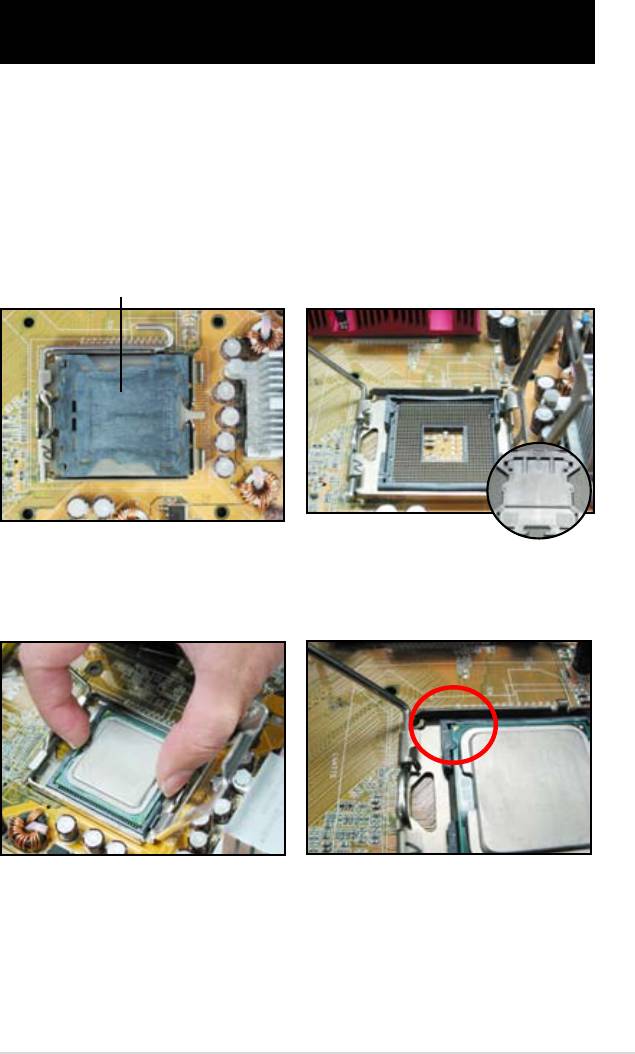
1.1 Installieren der CPU
1.1.1 Intel LGA775-Sockel
1. Suchen Sie den CPU-Sockel auf
2. Lösen Sie den Rückhaltehebel
dem Motherboard.
und heben Sie mit ihrem Daumen
die Deckplatte an.
Schieben Sie dann die
PnP-Abdeckung von dem
Deckplattenfenster, um sie
Pick and Place Abdeckung (PnP Cap)
auszubauen.
3. Positionieren Sie den CPU über
4. Stellen Sie sicher, dass das
dem Sockel.
goldene Dreieck im linken, unteren
Eck des Sockels ist.
ASUS Motherboard Installationshilfe 1-1

5. Die Sockel-Ausrichtungs-Kodierung muss mit der CPU-Auskerbung
zusammenpassen.
6. Schließen Sie die Deckplatte und schieben Sie den Deckhebel so lange, bis
er in der Rückhalterung einrastet.
Die CPU passt nur in eine
Richtung hinein. Stecken Sie
die CPU nicht mit übermäßiger
Kraft in den Steckplatz
ein, um ein Verbiegen der
Sockelkontaktstifte und Schäden
an der CPU zu vermeiden.
1.1.2 Intel LGA1366-Sockel
Rückhalteklemme
1. Suchen Sie den CPU-Sockel auf dem
A
Motherboard.
2. Drücken Sie mit Ihren Daumen auf
den Hebel (A) und drücken sie ihn
dann nach links (B), bis er sich von
B
der Befestigungsklemme löst.
Befestigungshebel
Um Beschädigungen der
Sockelskontakte zu vermeiden,
entfernen Sie NICHT die
PnP-Kappe, es sei denn, Sie
Befestigungsplatte
installieren einen Prozessors.
4
3. Heben Sie den Hebel in
Pfeilrichtung um 135º an.
4. Heben Sie die Platte mit Daumen
und Zeigenger um 100º an.
3
1-2 Kapitel 1: Schneller Aufbau
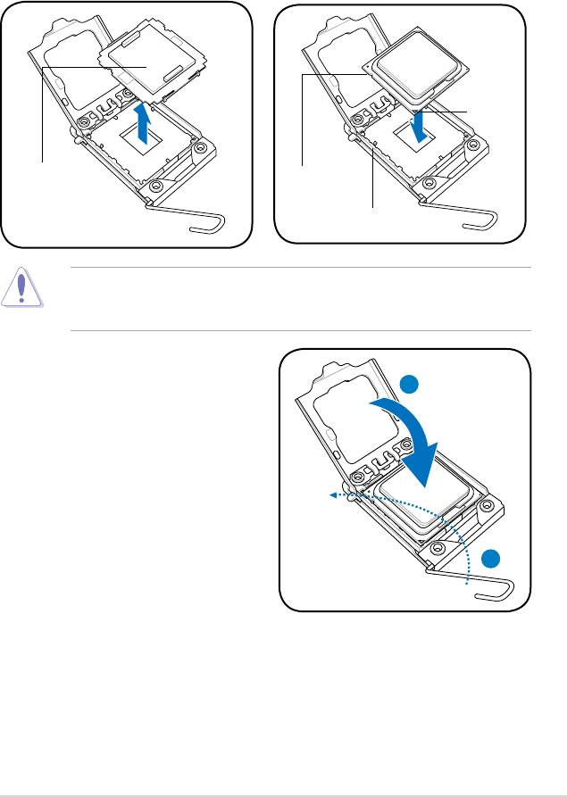
5. Entfernen Sie die PnP-Kappe vom
6. Platzieren Sie die CPU über dem
CPU-Sockel.
Sockel und vergewissern Sie sich,
dass das goldene Dreieck in die
untere linke Ecke des Sockels zeigt.
Richten Sie den Ausrichtungszapfen
mit der CPU-Kerbe aus.
Goldenes
Dreieck
PnP-Kappe
CPU-Kerbe
Ausrichtungszapfen
Die CPU passt nur in der Richtigen Ausrichtung. Wenden Sie KEINE Gewalt
an, um die CPU in den Sockel einzustecken, um ein verbiegen der Kontakte am
Sockel und eine Beschädigung des Prozessors zu vermeiden!
8. Schließen Sie die
Befestigungsplatte (A) und drücken
A
Sie dann auf den Hebel (B), bis
dieser in der Befestigungsklemme
einrastet.
B
ASUS Motherboard Installationshilfe 1-3
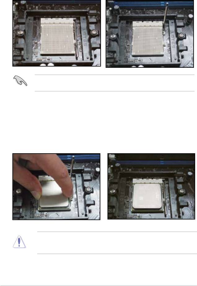
1.1.3 AMD AM2-Sockel
1. Suchen Sie den CPU-Sockel auf
2. Drücken Sie den Hebel seitwärts,
dem Motherboard.
um den Sockel zu entriegeln und
heben Sie ihn um 90º an.
Vergewissern Sie sich, dass der Sockelhebel um 90º angehoben wurde.
Anderenfalls wird der Prozessor nicht richtig passen.
3. Platzieren Sie die CPU über dem
4. Wenn die CPU eingesetzt wurde,
Sockel, so dass die CPU-Ecke
drücken Sie den Sockelhebel
mit dem goldenen Dreieck mit
hinunter, um den Prozessor zu
dem Dreieck an der Sockelecke
sichern. Der Hebel rastet an der
übereinstimmt.
seitlichen Klemme ein und zeigt
somit an, dass er richtig befestigt ist.
Setzen Sie die CPU vorsichtig in den
Sockel ein, bis sie richtig sitzt.
Die CPU passt nur in der Richtigen Ausrichtung. Wenden Sie KEINE Gewalt
an, um die CPU in den Sockel einzustecken, um ein verbiegen der Kontakte am
Sockel und eine Beschädigung des Prozessors zu vermeiden!
1-4 Kapitel 1: Schneller Aufbau
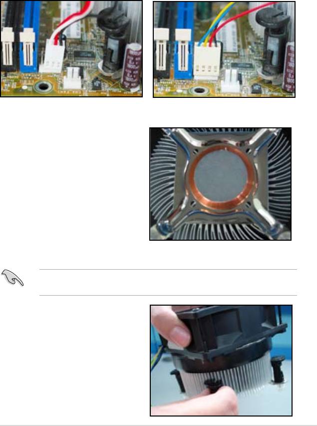
1.2 Installieren des Kühlkörpers und Lüfters
Zum Installieren des CPU-Kühlkörpers und Lüfters:
1. Wählen Sie einen Intel-geprüften oder AMD-geprüften Kühlkörper und
Lüfter, der auf Ihrem Motherboard basiert. Es gibt 3-polige (links) und 4-
polige (rechts) Lüfteranschlüsse. Nur CPU-Lüfter mit 4-poligem Anschluss
unterstützen die ASUS Q-Lüfter-Technologie.
Für Intel-geprüfte Kühlkörper:
2. Einige Kühlkörper sind mit einer
Wärmeleitpaste versehen. Falls
dies der Fall ist, kratzen Sie
diese nicht ab und entfernen Sie
den Schutzlm erst kurz vor der
Installation. Falls dies nicht der Fall
ist, bringen Sie an allen Stellen, an
denen die CPU mit dem Kühlkörper
Kontakt haben wird, Kühlpaste an,
und installieren Sie den Kühlkörper
erst danach. Vergewissern Sie sich,
dass die Paste in einer gleichmäßig
dünnen Schicht verteilt ist.
Um das Verschmutzen der Paste zu verhindern, tragen Sie sie bitte NICHT
direkt mit den Fingern auf.
3. Richten Sie jede Klemme mit dem
schmalen Ende der Kerbe nach
außen aus.
ASUS Motherboard Installationshilfe 1-5
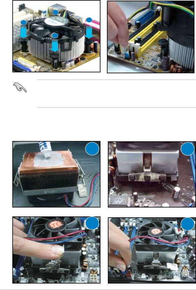
4. Drücken Sie jeweils zwei
5. Verbinden Sie das CPU-Lüfterkabel
gegenüberliegende Klemmen zur
mit dem entsprechenden
selben Zeit nach unten, um den
Anschlussteil am Motherboard.
Kühlkörper und den Lüfter an ihrem
Platz zu befestigen.
B
A
A
B
Vergessen Sie auf keinen Fall, den CPU-Lüfter anzuschließen! Hardware-
Überwachungsfehler können auftreten, wenn Sie vergessen, diese Verbindung
herzustellen, und wir empfehlen einen drehbaren Kühler, um die maximale
Hitzeabfuhr zu gewährleisten.
Für AMD-geprüfte Kühlkörper:
Folgen Sie bitte den unten aufgeführten Anweisungen, um einen AMD-geprüften
Kühlkörper zu installieren.
1
2
3
4
1-6 Kapitel 1: Schneller Aufbau
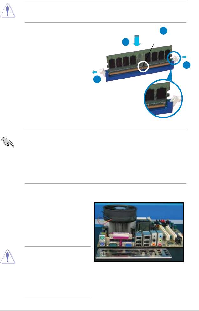
1.3 Installieren eines DIMMs
Trennen Sie unbedingt das System vom Netz, bevor Sie DIMMs oder andere
Systemkomponenten hinzufügen oder entfernen. Ansonsten können sowohl das
Motherboard als auch die Komponenten schwer beschädigt werden.
2
1. Drücken Sie die Haltebügel nach
außen, um den DIMM-Steckplatz
DDR2 DIMM-Kerbe
3
zu entriegeln.
2. Richten Sie ein DIMM-Modul auf
den Steckplatz aus, so dass die
1
Kerbe am DIMM-Modul an die
Unterbrechung des Steckplatzes
1
passt.
3. Stecken Sie das DIMM-Modul
fest in den Steckplatz ein, bis die
Haltebügel zurückschnappen und
das DIMM-Modul richtig sitzt.
Entriegelter Haltebügel
• Ein DDR2-DIMM lässt sich aufgrund einer Kerbe nur in eine Richtung
einpassen. Stecken Sie ein DIMM nicht gewaltsam in einen Steckplatz, da
es sonst beschädigt werden könnte.
• Nehmen Sie bei der Installation von zwei oder mehr DIMMs das im
Motherboard-Paket enthaltene Benutzerhandbuch zu Hilfe.
• Eine Liste qualizierter Anbieter für Speichermodule nden Sie ebenfalls im
Benutzerhandbuch des Motherboards.
1.4 Installation des Motherboards
1. Die E/A-Anschlüsse unterscheiden
sich von Motherboard zu
Motherboard. Nutzen und
installieren Sie nur die rückseitige
E/A-Blende, die mit dem
Motherboard geliefert wurde.
Einige scharfe Ecken und
Kanten können Verletzungen
verursachen. Wir empfehlen,
vor der Installation des
Motherboards und der E/A-
Blende schnittfeste und gegen
Durchstechen widerstandsfähige
Handschuhe an zu ziehen.
ASUS Motherboard Installationshilfe 1-7
2. Befestigen Sie die Abstandsbolzen
3. Die Federn an den Ecken der
durch die passenden
E/A-Blende können die E/A-Ports
Schraubenlöcher auf der Metalplatte.
beschädigen. Seien Sie beim
Einbauen der E/A-Blende vorsichtig!
5. Setzen Sie lose alle Schauben in
4. Positionieren Sie die E/A-Seite
diagonaler Sequenz ein. Wenn
des Motherboards zum Rand des
alle Schauben an ihrem Platz
Gehäuses und platzieren Sie das
sind, ziehen Sie die Schauben fest
Motherboard im Gehäuse.
— aber nicht ZU fest!
• Sie sollten die Steckplatzabdeckungsblende der Erweiterungskarten an
der Rückseite des Gehäuses entfernen, bevor Sie mit der Installation
des Motherboards beginnen. Bei einigen Gehäusemodellen könnte es
schwer sein, die Erweiterungssteckplatzabdeckung nach der Installation zu
entfernen
• Ziehen Sie die Schrauben nicht zu fest. Anderenfalls könnte das
Motherboard beschädigt werden!
1-8 Kapitel 1: Schneller Aufbau
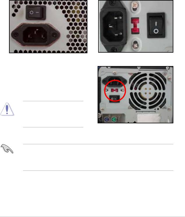
1.5 Installieren des Netzteils
Es gibt zwei Arten von häug genutzten Netzteilen: eines mit aktiver
Spannungswahl und ein anderes mit passiver Spannungswahl.
1. Wählen sie ein Netzteil aus.
Netzteil mit aktiver
Netzteil mit passiver
Spannungswahl:
Spannungswahl:
Aktive Spannungswahl welche
Bei der passiven Spannungswahl
die Eingangswechselspannung
muss der Benutzer die
korrigiert.
Eingangswechselspannung
abstimmen.
2. Falls Sie ein Netzteil mit
passiver Spannungswahl
benutzen, sollten Sie die korrekte
Eingangswechselspannung für
Ihre Region einstellen.
Fehler in der Abstimmung der
Stromversorgung über das
Netzteil können zu ernsthaften
Schäden am System führen!
Nutzen Sie nur Netzteile mit Sicherheitszertikat. Die Nutzung von
unbeständigen Netzteilen können ihr Motherboard und andere Komponenten
beschädigen. Beziehen Sie auch das Benutzerhandbuch des Netzteils mit ein
welches auf Ihre Motherboard-Anforderungen eingeht.
ASUS Motherboard Installationshilfe 1-9
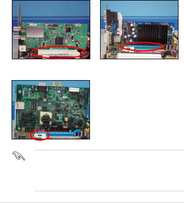
1.6 Installieren einer Erweiterungskarte
Anleitung zum Installieren einer Erweiterungskarte:
1. Entfernen Sie die Steckplatzabdeckungsblende gegenüber des
Erweiterungskarten-Steckplatzes, in dem Sie die Erweiterungskarte gerne
installieren möchten.
2. Setzen Sie die Erweiterungskarte ein und stellen Sie sicher, das Sie richtig im
Steckplatz sitzt!
3. Schrauben Sie die Karte fest, um ein sicheren Halt zu gewährleisten.
4. Wiederholen Sie die oben aufgeführten Schritte bei der Installation anderer
Erweiterungskarten.
PCI-Karte PCIE x16-Karte
PCIE x1-Karte
• Bitte ziehen Sie die Anleitung der Erweiterungskarte hinzu, um Details zur
Kartenkonguration zu erfahren und konsultieren Sie die Betriebsanleitung
des Motherboards, falls Sie nach dem Installieren der Erweiterungskarte
noch Jumper kongurieren müssen.
• Verwenden Sie außerdem das Benutzerhandbuch des Motherboards für die
Anleitung zur Verbindung des Erweiterungskarten-Kabels.
1-10 Kapitel 1: Schneller Aufbau
1.7 Installation des Laufwerks
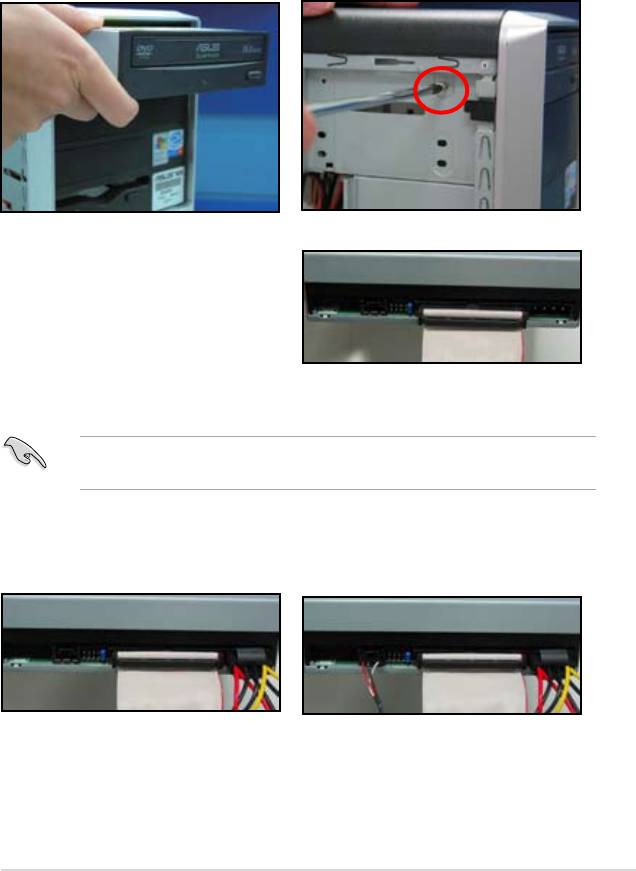
1.7.1 Optisches PATA Laufwerk
1. Entfernen Sie die Abdeckblende
2. Richten Sie es auf die
und schieben Sie das optische
Schraubenlöcher aus und xieren
Laufwerk in den Schacht.
sie das Laufwerk mit Schrauben.
3. Richten Sie das IDE-Kabel aus
und stecken Sie es in das optische
Laufwerk. Der rote Markierung
am IDE-Kabel kennzeichnet Pin1
und muss mit Pin1 am optischen
Laufwerk übereinstimmen.
IDE-Kable sind mit Absicht speziell gepolt. Versuchen Sie niemals, das IDE-
Kabel mit Gewalt einzustecken, wenn die Pole nicht passen.
4. Verbinden Sie das 4-polige
5. Fügen Sie das Audio-Kabel an
Stromkabel mit dem optischen
den Anschluss des optischen
Laufwerk.
Laufwerks hinzu.
ASUS Motherboard Installationshilfe 1-11
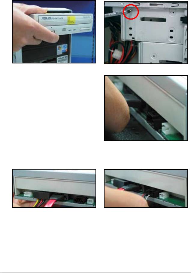
1.7.2 Optisches SATA Laufwerk
1. Entfernen Sie die Abdeckblende
2. Richten Sie es auf die
und schieben Sie das optische
Schraubenlöcher aus und xieren
Laufwerk in den Schacht.
Sie das Laufwerk mit Schrauben.
3. Richten Sie das SATA-Kabel
aus und stecken Sie es in das
optische Laufwerk. SATA-Kabel
sind besonders gepolt. Versuchen
Sie niemals, das SATA-Kabel mit
Gewalt einzustecken.
4. Verbinden Sie das SATA-
5. Fügen Sie das Audio-Kabel an
Stromkabel mit dem optischen
den Anschluss des optischen
Laufwerk.
Laufwerks hinzu.
1-12 Kapitel 1: Schneller Aufbau
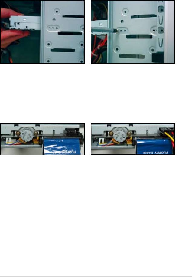
1.7.3 Diskettenlaufwerk
1. Entfernen Sie die Abdeckblende
2. Richten Sie es auf die
und schieben Sie das
Schraubenlöcher aus und xieren
Diskettenlaufwerk in den Schacht.
Sie das Laufwerk mit Schrauben.
3. Richten Sie das Disketten-Interface-
4. Verbinden sie das Disketten-
Kabel aus und stecken Sie es in
Stromkabel mit dem Anschluss
das Diskettenlaufwerk. Der rote
auf der Rückseite des
Markierung am Kabel kennzeichnet
Diskettenlaufwerks.
Pin1 und muss mit Pin1 am
Diskettenlaufwerk übereinstimmen.
ASUS Motherboard Installationshilfe 1-13
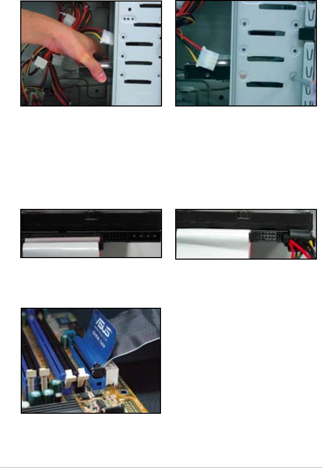
1.7.4 PATA Festplattenlaufwerk
1. Setzen Sie das PATA
2. Richten Sie es auf die
Festplattenlaufwerk in den Schacht
Schraubenlöcher aus und xieren
ein.
Sie das Laufwerk mit Schrauben.
3. Richten Sie das Signalkabel auf
4. Verbinden Sie das 4-polige
das Festplattenlaufwerk aus und
Stromkabel mit dem Anschluss
verbinden Sie es. Der rote Streifen
auf der Rückseite des
am Kabel ist das Pin1-Ende.
Festplattenlaufwerks.
Verbinden Sie das Kabel mit der
Anschlussstelle und wenden Sie
dazu auf keinen Fall Kraft an!
5. Verbinden Sie das andere Ende des
Signalkabels mit der Anschlussstelle
am Motherboard.
1-14 Kapitel 1: Schneller Aufbau
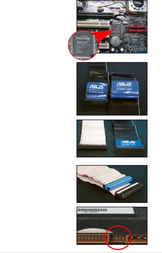
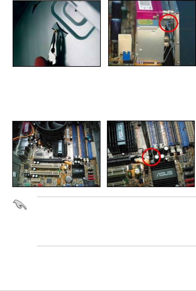
Anmerkungen zur Installation des Festplattenlaufwerks
• Falls Ihr Betriebssystem auf
Festplattenlaufwerken installiert
wurde, die von RAID oder anderen
Controllern überwacht werden,
so müssen Sie zuerst die Treiber
für diese Laufwerkscontroller
installieren.
• Die Kabel sind mit Öffnungslaschen
ausgestattet. Installieren Sie die
Laufwerke so, wie es auf den
Kabeletiketten steht. Um Schäden
an den Polen zu verhindern, sollten
Sie die Öffnungslaschen zum
Herausziehen der Kabel nutzen.
• Es gibt 2 Arten von Kabel für ATA
IDE Laufwerke: Neue 80-adrige
(rechts) und ältere 40-adrige (links)
Für ATA66/100/133 Laufwerke
können nur die 80-adrigen Kabel
die optimale Leistung vermitteln.
Die 40-adrigen Kabel werden
normalerweise für optische
Laufwerke verwendet.
• Die Kabelanschlüsse sind farblich
gekennzeichnet: ein blauer für
den Host-Anschluss, und ein
schwarzer/grauer für das primäre/
sekundäre Festplattenlaufwerk.
• Wenn Sie zwei IDE Geräte
anschließen, müssen Sie darauf
achten, dass ein Jumper auf
“master” und einer auf “slave”
eingestellt sind. Falls Sie allerdings
ein 80-adriges Kabel benutzen,
können Sie auch “cable select”
wählen.
ASUS Motherboard Installationshilfe 1-15
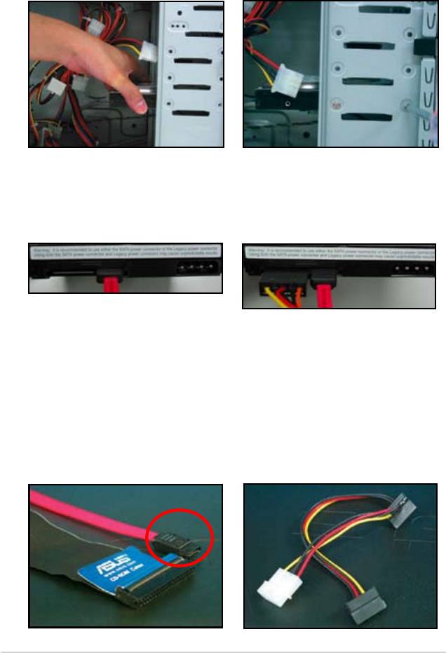
1.7.5 SATA-Festplattenlaufwerk
1. Setzen Sie das SATA-
2. Richten Sie es auf die
Festplattenlaufwerk in den Schacht
Schraubenlöcher aus und xieren
ein.
Sie das Laufwerk mit Schrauben.
3. Richten Sie das Signalkabel auf
4. Verbinden Sie das 4-polige
das Festplattenlaufwerk aus und
Stromkabel mit dem Anschluss
verbinden Sie es. Das Kable kann
auf der Rückseite des
nur in einer Richtung angebracht
Festplattenlaufwerks.
werden.
Anmerkung zum installieren des SATA Festplattenlaufwerks
• Die SATA-Schnittstelle hat eine
• Der Anschluss des SATA-
schnellere Datenübertragungsrate
Stromkabels unterscheidet sich
und eine bessere
von den traditionellen 4-poligen
Spannungstoleranz. Das schmale
Stromanschlüssen. Das ASUS
Design des SATA-Kabels löst
Motherboard enthält auch ein
zudem Verkabelungsprobleme
Adapterkabel, für den Fall, dass
und ermöglicht einen besseren
Ihr Stromanschluss diesen neuen
Luftstrom im Gehäuse.
Anschluss nicht besitzt.
1-16 Kapitel 1: Schneller Aufbau
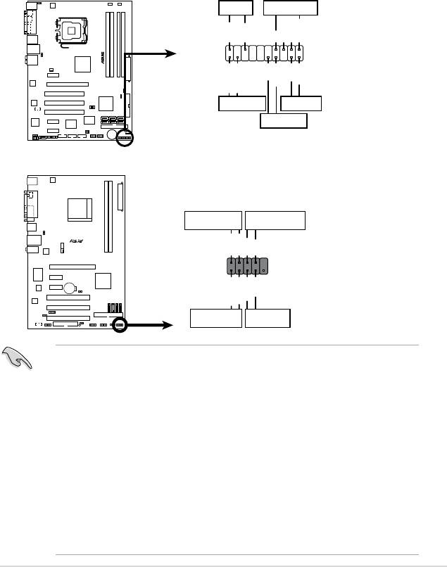
1.8 Frontblendenkabel
Um die Frontblendenkabel zu verbinden:
• RESET (Reset-Knopf)
• PLED (Power-LED)
• PWRSW (Power-Knopf)
• IDE_LED (IDE Festplatte aktiv-LED)
• SPEAKER (Lautsprecheranschluss)
ASUS Motherboard Installationshilfe 1-17
PWR LED PWR BTN
M2N-X
PLED+
PLED-
PWR
GNDReset
F_PANEL
Ground
IDELED+
IDELED-
HD LED RESET
PLED SPEAKER
P5B-E
PLED+
PLED-
+5V
Ground
Ground
Speaker
®
PANEL
PWR
Reset
Ground
Ground
IDE_LED+
IDE_LED-
IDE_LED
RESET
PWRSW
*
Requires an ATX power supply.
20-8-poliger Frontblendenanschluss
PIN1
PIN1
10-1-poliger Frontblendenanschluss
• Die Frontblendenkabel können sich von Modell und Ausstattung
unterscheiden. Verbinden Sie die Kabel mit dem Motherboard
entsprechend der Beschriftung.
• Falls die LEDs nicht korrekt aueuchten, obwohl Sie alles richtig
angeschlossen haben, kann es sein, dass Sie den Stecker nur falsch
herum installiert haben. Gewöhnlich steht der weiße Draht für den Hauptpin
und der farbig markierte Draht für den Signalpin.
• Die SPEAKER, RESET und PWRSW Frontblendenkabel haben keine
spezielle Orientierung, so wie es die IDE_LED oder PLED-Kabel
haben. Verbinden Sie die PIN1 Kabel mit der Anschlussstelle PIN1 am
Motherboard.
• Die Frontblendenanschlüsse variieren je nach Modell des Motherboards.
Wenden Sie sich für nähere Informationen an das Benutzerhandbuch.
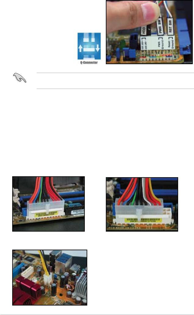
ASUS Q-Connector
Die ASUS Q-Connector spart
Zeit und befreit Sie vom lästigen
Kabelgewirr der Frontblendenkabel.
Für Details konsultieren Sie bitte das
Benutzerhandbuch.
Der Q-Connector ist nur für ausgewählte Modelle verfügbar. Für nähere
Informationen schauen Sie bitte in das Benutzerhandbuch.
1.9 Verbindung der ATX-Stromverbindung
Die ATX-Stromanschlüsse passen nur in einer Richtung. Benutzen Sie den
Seitenclip, um das Netzteil sicher mit dem Motherboard zu verbinden. Wenden
Sie KEINE Gewalt an, um den männlichen Stromanschluss in den weiblichen
Anschlussstecker zu stecken. Gewöhnlich sind 2 Anschlüsse am Motherboard,
ein 24-poliger und ein 4-poliger Stromanschluss. Einige ältere Modelle haben
nur einen 20-poligen Stromanschluss, welcher aber auch auf den 24-poligen
Stromanschluss des Motherboards passt.
20-poliger Stromanschluss
24-poliger Stromanschluss
(auf einem 24-poligen weiblicher Gegenstecker)
4-poliger Stromanschluss
1-18 Kapitel 1: Schneller Aufbau
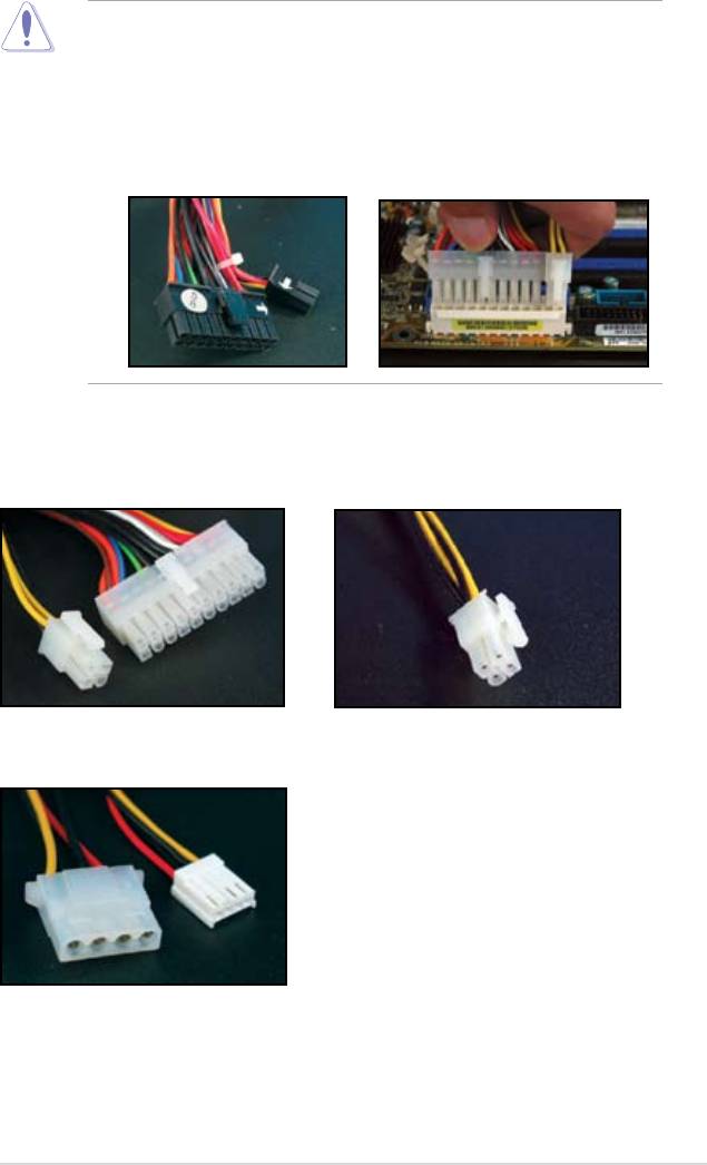
• Während Sie die Stromversorgung an das Motherboard anschließen, darf
kein externer Wechselstrom an das Netzteil angeschlossen sein.
• Stellen Sie sicher, dass der Stromanschluss fest am Motherboard befestigt
ist.
• Falls Ihr Stromanschluss einen 20-poligen und einen 4-poligen Anschluss
bietet, können Sie diese beiden auch kombinieren und dann den 24-poligen
Anschluss am Motherboard anbringen.
Stromanschlüsse
20+4 (24)-poliger ATX-Anschluss
4-poliger ATX-Anschluss
Stromanschluss für Peripherie (links)
Disketten Stromanschluss (rechts)
ASUS Motherboard Installationshilfe 1-19
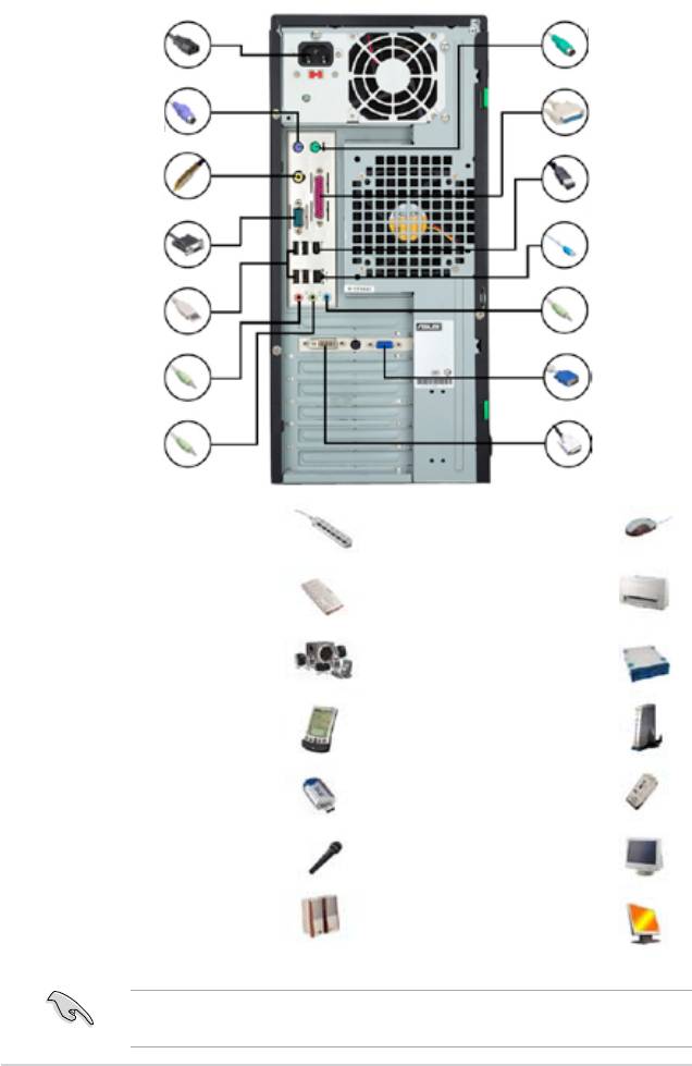
1.10 Peripheriegeräte und Zusatzgeräte
Beziehen Sie sich auf die folgende Abbildung, um die peripheren Geräte und
Zusatzgeräte anzuschließen.
1.Netzkabelanschluss
8. PS/2 Maus-
Anschluss
2. PS/2 Tastatur-
9. Paralell-
Anschluss
Anschluss
3. S/PDIF-
10. IEEE1394-
Ausgang
Anschluss
4. Serieller
11. LAN (RJ45)
Anschluss
Anschluss
5. USB-
12. Line-In-
Anschlusst
Anschluss
13. Video-Grak-
6. Mikrofon-
Adapter-Anschluss
Anschluss
7. Lautsprecher-
14. DVI — Anschluss
Anschluss
1. Netzkabelanschluss +
8. 8. PS/2-Mausanschluss
Verlängerungskabel
+ Maus
2. PS/2 Tastaturanschluss +
9. Parallelanschluss +
Tastatur
Drucker
3. S/PDIF-Ausgang
10. IEEE1394-Anschluss +
+ digitales 5.1
Festplattenlaufwerk
Lautsprechersystem
4. Serieller Anschluss +
11. LAN (RJ45) Anschluss +
PDA-Dock
Modem
5. USB-Anschluss + USB
12. Line-In-Anschluss +
Gerät
Aufnahmegerät
6. Mikrofonanschluss +
13. VGA-Anschluss + CRT
Mikrofon
Monitor
7. Line-Out +
14. DVI-Anschluss + LCD
Lautsprecher
Monitor
Anschluss
Die Anschlüsse an der Hinterseite variieren je nach Model. Nähere
Informationen siehe Benutzerhandbuch.
1-20 Kapitel 1: Schneller Aufbau

1.11 Erstes Einschalten
Das System startet den Power-On Self Test — kurz POST. Während dieses Tests
ertönen BIOS Pieptöne (die Codes hierfür nden Sie in der folgenden Tabelle).
BIOS-Piepton Beschreibung
Ein langer Piepton gefolgt von drei
Keine Grakkarte erkannt
kurzen
Ein langer Piepton gefolgt von zwei
Kein Arbeitsspeicher erkannt
kurzen und einer Pause (wiederholt)
Ein langer Piepton gefolgt von vier
Hardware-Komponentenfehler
kurzen
(AMI BIOS)
Vier kurze Pieptöne Hardware-Komponentenfehler
(AWARD BIOS)
Problembehebung
Problem Lösung
• Sie können den Computer
Stellen Sie sicher das der Stromstecker richtig
nicht einschalten.
angeschlossen ist.
• Strom LED leuchtet nicht.
• Netzgebläse arbeitet nicht.
Der Computer ist
— Überprüfen Sie, ob der Bildschirm eingeschaltet ist und
eingeschaltet, aber der
ob das VGA-Kabel richtig verbunden ist.
Bildschirm ist schwarz.
— Stellen Sie Monitorhelligkeit- und kontrast ein.
— Fahren Sie den Computer herunter und entfernen Sie
das Stromkabel. Überprüfen Sie, ob die VGA Karte fest
eingebaut ist.
Speicherkarte wird nicht
— Stellen Sie sicher, dass das Speichermodul richtig
erkannt
eingestellt ist
— Stellen Sie sicher, dass die DIMMS fest auf dem DIMM-
Sockel angebracht sind
— Stellen Sie sicher, dass das Speichermodul von einem
auf der Liste Qualierter Anbieter aufgeführten Händler
gekauft wurde. Weitere Informationen siehe QVL-
Benutzerhandbuch.
Diskettenfehler
— Überprüfen Sie die BIOS Konguration des
(Der Indikator hierfür ist eine
Diskettenlaufwerks.
aueuchtende Warnmitteilung
— Stellen Sie sicher, dass die Kabel des Diskettenlaufwerks
auf dem Bildschirm)
richtig eingesteckt sind.
Fehler des Festplatten-
— Stellen Sie sicher, dass der Jumper richtig eingestellt ist
oder Optisches-Laufwerks
(Master/Slave)
(nicht gefunden oder nicht
— Überprüfen Sie die BIOS Konguration des Festplatten-
und Optischen-Laufwerks.
ausgeführt)
— Stellen Sie sicher, dass die Gerätekabel fest
angeschlossen sind.
— Stellen Sie sicher, dass die Gerätetreiber richtig installiert
sind.
ASUS Motherboard Installationshilfe 1-21