
B75M-PLUS

Регистрация устройства поможет вам управлять его гарантией, получать техническую поддержку и отслеживать статус ремонта.
Регистрация продукта
Руководства пользователя
Версия T8250
4.94 MB
B75M-PLUS User’s Manual(Traditional Chinese)
Версия J8391
5.09 MB
B75M-PLUS User’s Manual(Japanese)
Версия E10276
91.95 KB
HDMI insert (English)
Версия F8391
4.79 MB
B75M-PLUS user’s manual(French)
Версия Q8250
7.05 MB
B75M-PLUS Quick Start Guide for Multiple Languages
Версия E8250
3.4 MB
B75M-PLUS User’s Manual (English)
Версия C8250
4.83 MB
B75M-PLUS User’s Manual (Simplified Chinese)
-
-
Инструкции по эксплуатации
-
Материнские платы
-
ASUS
-
B75M-+
-
Инструкция по эксплуатации
| Языки: |
Французский |
|---|---|
| Страницы: | 72 |
| Описание: | B75M-PLUS user’s manual(French) |
Стр.
из
результат(ов) по запросу ««
×
|
|
NoDevice
Loading…
-
« Назад
Ctrl + ←
-
Вперёд »
Ctrl + →
Мануал подходит для устройств
-
ASUS B75M-+
-
ASUS B75M-PLUS
ASUS
B75MPLUS Руководство по эксплуатации
Популярность:
1064 просмотры
Подсчет страниц:
69 страницы
Тип файла:
Размер файла:
3.4 Mb
ASUS B75M-PLUS
Australia statement notice
From 1 January 2012 updated warranties apply to all ASUS products, consistent with the Australian
Consumer Law. For the latest product warranty details please visit http://support.asus.com. Our goods
come with guarantees that cannot be excluded under the Australian Consumer Law. You are entitled to a
replacement or refund for a major failure and compensation for any other reasonably foreseeable loss or
damage. You are also entitled to have the goods repaired or replaced if the goods fail to be of acceptable
quality and the failure does not amount to a major failure.
If you require assistance please call ASUS Customer Service 1300 2787 88 or visit us at
http://support.asus.com
Motherboard Layout
Step 1
Step 5
Step 4
Step 7
Step 3
Step 7
Step 2
B75M-PLUS
PCIEX16
PCIEX1_1
PCI1
F_PANEL
SPEAKER
CLRTC
SPDIF_OUT
LPT
USBPWF
KB_USBPWB
USB56
USB78
AAFP
ATX12V
EATXPWR
CPU_FAN
CHA_FAN
BATTERY
Super
I/O
ALC
887
RTL
8111G
DIGI
+VRM
8MB
BIOS
SB_PWR
LGA1155
Intel
®
B75
DDR3 DIMM_A1 (64bit, 240-pin module)
DDR3 DIMM_A2 (64bit, 240-pin module)
DDR3 DIMM_B1 (64bit, 240-pin module)
DDR3 DIMM_B2 (64bit, 240-pin module)
SATA3G_4
SATA3G_5
SATA6G_1
SATA3G_1
SATA3G_2
SATA3G_3
AUDIO
KBMS
LAN1_USB12
USB3_12
USB34
HDMI
DVI_VGA
COM
USB3_34

B75M-PLUS
Motherboard

E8250
First Edition
April 2013
Copyright © 2013 ASUSTeK COMPUTER INC. All Rights Reserved.
No part of this manual, including the products and software described in it, may be reproduced,
transmitted, transcribed, stored in a retrieval system, or translated into any language in any form or by any
means, except documentation kept by the purchaser for backup purposes, without the express written
permission of ASUSTeK COMPUTER INC. (“ASUS”).
Product warranty or service will not be extended if: (1) the product is repaired, modied or altered, unless
such repair, modication of alteration is authorized in writing by ASUS; or (2) the serial number of the
product is defaced or missing.
ASUS PROVIDES THIS MANUAL “AS IS” WITHOUT WARRANTY OF ANY KIND, EITHER EXPRESS
OR IMPLIED, INCLUDING BUT NOT LIMITED TO THE IMPLIED WARRANTIES OR CONDITIONS OF
MERCHANTABILITY OR FITNESS FOR A PARTICULAR PURPOSE. IN NO EVENT SHALL ASUS, ITS
DIRECTORS, OFFICERS, EMPLOYEES OR AGENTS BE LIABLE FOR ANY INDIRECT, SPECIAL,
INCIDENTAL, OR CONSEQUENTIAL DAMAGES (INCLUDING DAMAGES FOR LOSS OF PROFITS,
LOSS OF BUSINESS, LOSS OF USE OR DATA, INTERRUPTION OF BUSINESS AND THE LIKE),
EVEN IF ASUS HAS BEEN ADVISED OF THE POSSIBILITY OF SUCH DAMAGES ARISING FROM ANY
DEFECT OR ERROR IN THIS MANUAL OR PRODUCT.
SPECIFICATIONS AND INFORMATION CONTAINED IN THIS MANUAL ARE FURNISHED FOR
INFORMATIONAL USE ONLY, AND ARE SUBJECT TO CHANGE AT ANY TIME WITHOUT NOTICE,
AND SHOULD NOT BE CONSTRUED AS A COMMITMENT BY ASUS. ASUS ASSUMES NO
RESPONSIBILITY OR LIABILITY FOR ANY ERRORS OR INACCURACIES THAT MAY APPEAR IN THIS
MANUAL, INCLUDING THE PRODUCTS AND SOFTWARE DESCRIBED IN IT.
Products and corporate names appearing in this manual may or may not be registered trademarks or
copyrights of their respective companies, and are used only for identication or explanation and to the
owners’ benet, without intent to infringe.
Offer to Provide Source Code of Certain Software
This product contains copyrighted software that is licensed under the General Public License (“GPL”),
under the Lesser General Public License Version (“LGPL”) and/or other Free Open Source Software
Licenses. Such software in this product is distributed without any warranty to the extent permitted by the
applicable law. Copies of these licenses are included in this product.
Where the applicable license entitles you to the source code of such software and/or other additional data,
you may obtain it for a period of three years after our last shipment of the product, either
(1) for free by downloading it from http://support.asus.com/download
or
(2) for the cost of reproduction and shipment, which is dependent on the preferred carrier and the location
where you want to have it shipped to, by sending a request to:
ASUSTeK Computer Inc.
Legal Compliance Dept.
15 Li Te Rd.,
Beitou, Taipei 112
Taiwan
In your request please provide the name, model number and version, as stated in the About Box of the
product for which you wish to obtain the corresponding source code and your contact details so that we
can coordinate the terms and cost of shipment with you.
The source code will be distributed WITHOUT ANY WARRANTY and licensed under the same license as
the corresponding binary/object code.
This offer is valid to anyone in receipt of this information.
ASUSTeK is eager to duly provide complete source code as required under various Free Open Source
Software licenses. If however you encounter any problems in obtaining the full corresponding source
code we would be much obliged if you give us a notication to the email address gpl@asus.com, stating
the product and describing the problem (please DO NOT send large attachments such as source code
archives, etc. to this email address).
ii

Contents
Safety information ………………………………………………………………………………………… iv
About this guide …………………………………………………………………………………………… iv
Package contents …………………………………………………………………………………………. vi
B75M-PLUS specications summary …………………………………………………………….. vi
Chapter 1: Product introduction
1.1 Before you proceed ………………………………………………………………………….. 1-1
1.2 Motherboard overview ………………………………………………………………………
1.3 Central Processing Unit (CPU) …………………………………………………………..
1.4 System memory ………………………………………………………………………………..
1.5 Expansion slots ………………………………………………………………………………
1.6 Jumpers
1.7 Connectors ……………………………………………………………………………………..
1.9 Onboard LEDs ………………………………………………………………………………..
1.10 Software support …………………………………………………………………………….
…………………………………………………………………………………………. 1-11
Chapter 2: BIOS information
2.1 Managing and updating your BIOS …………………………………………………….2-1
2.2 BIOS setup program ………………………………………………………………………….
2.3 Main menu ………………………………………………………………………………………..
2.4 Ai Tweaker menu …………………………………………………………………………….
2.5 Advanced menu ………………………………………………………………………………
2.6 Monitor menu ………………………………………………………………………………….
2.7 Boot menu ………………………………………………………………………………………
2.8 Tools menu ……………………………………………………………………………………..
2.9 Exit menu ……………………………………………………………………………………….
1-10
1-13
1-21
1-22
2-11
2-17
2-24
2-27
2-33
2-34
1-1
1-3
1-7
2-6
2-9
Appendices
Notices ……………………………………………………………………………………………………… A-1
iii

Safety information
Electrical safety
To prevent electrical shock hazard, disconnect the power cable from the electrical outlet
•
before relocating the system.
When adding or removing devices to or from the system, ensure that the power cables
•
for the devices are unplugged before the signal cables are connected. If possible,
disconnect all power cables from the existing system before you add a device.
Before connecting or removing signal cables from the motherboard, ensure that all
•
power cables are unplugged.
Seek professional assistance before using an adapter or extension cord. These devices
•
could interrupt the grounding circuit.
Ensure that your power supply is set to the correct voltage in your area. If you are not
•
sure about the voltage of the electrical outlet you are using, contact your local power
company.
If the power supply is broken, do not try to x it by yourself. Contact a qualied service
•
technician or your retailer.
Operation safety
Before installing the motherboard and adding devices on it, carefully read all the manuals
•
that came with the package.
Before using the product, ensure all cables are correctly connected and the power
•
cables are not damaged. If you detect any damage, contact your dealer immediately.
To avoid short circuits, keep paper clips, screws, and staples away from connectors,
•
slots, sockets and circuitry.
Avoid dust, humidity, and temperature extremes. Do not place the product in any area
•
where it may become wet.
Place the product on a stable surface.
•
If you encounter technical problems with the product, contact a qualied service
•
technician or your retailer.
About this guide
This user guide contains the information you need when installing and conguring the
motherboard.
How this guide is organized
This guide contains the following parts:
• Chapter 1: Product introduction
This chapter describes the features of the motherboard and the new technology it
supports.
• Chapter 2: BIOS information
This chapter tells how to change system settings through the BIOS Setup menus.
Detailed descriptions of the BIOS parameters are also provided.
iv
Where to nd more information
Refer to the following sources for additional information and for product and software
updates.
1. ASUS websites
The ASUS website provides updated information on ASUS hardware and software
products. Refer to the ASUS contact information.
2. Optional documentation
Your product package may include optional documentation, such as warranty yers,
that may have been added by your dealer. These documents are not part of the
standard package.
Conventions used in this guide
To ensure that you perform certain tasks properly, take note of the following symbols used
throughout this manual.
DANGER/WARNING: Information to prevent injury to yourself when trying to
complete a task.
CAUTION: Information to prevent damage to the components when trying to
complete a task
IMPORTANT: Instructions that you MUST follow to complete a task. .
NOTE: Tips and additional information to help you complete a task.
Typography
Bold text Indicates a menu or an item to select.
Italics
<Key> Keys enclosed in the less-than and greater-than sign
<Key1> + <Key2> + <Key3> If you must press two or more keys simultaneously, the key
Used to emphasize a word or a phrase.
means that you must press the enclosed key.
Example: <Enter> means that you must press the Enter or
Return key.
names are linked with a plus sign (+).
v

Package contents
Check your motherboard package for the following items.
Motherboard ASUS B75M-PLUS motherboard
Cables
Accessories 1 x I/O Shield
Application DVD Support DVD
Documentation User Guide
• If any of the above items is damaged or missing, contact your retailer.
• The illustrated items above are for reference only. Actual product specications may
vary with different models.
1 x Serial ATA 6.0 Gb/s cable
1 x Serial ATA 3.0 Gb/s cable
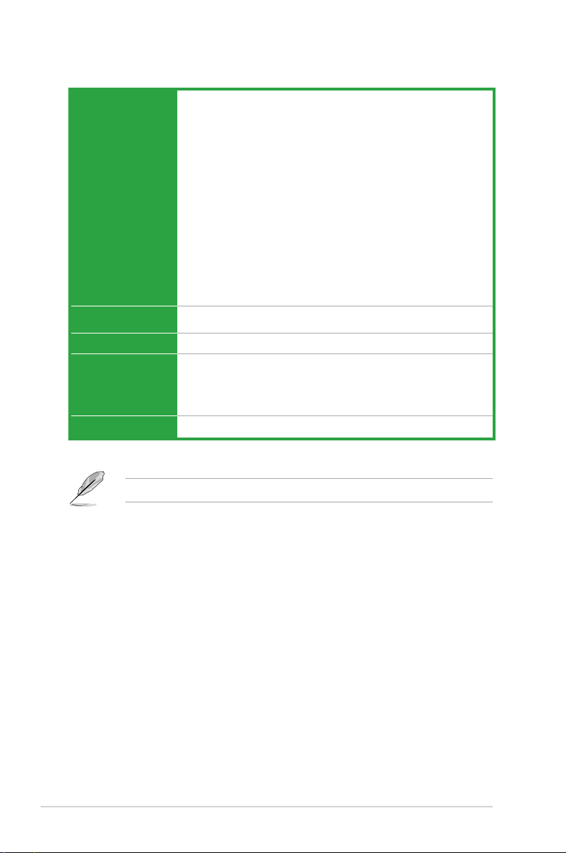
B75M-PLUS specications summary
CPU LGA1155 socket for Intel® 3rd / 2nd Generation Core i7 / i5 / i3, Pentium®
and Celeron® processors
Supports Intel® 22/32nm CPU
Supports Intel® Turbo Boost Technology 2.0
* The Intel® Turbo Boost Technology 2.0 support depends on the CPU types.
** Refer to www.asus.com for Intel® CPU support list.
Chipset Intel® B75 Express Chipset
Memory 4 x DIMM, max. 32GB, DDR3 2200 (O.C.) / 2133 (O.C.) / 2000 (O.C.) /
1866 (O.C.) / 1600 / 1333/ 1066 MHz, non-ECC,un-buffered memory
Dual-channel memory architecture
Supports Intel® Extreme Memory Prole (XMP)
* The maximum 32GB memory capacity can be supported with 8GB (or higher).
ASUS will update the QVL once the DIMMs are available in the market.
** Due to the CPU behavior, DDR3 2133/1866MHz memory module will run at DDR3
2000/1800MHz frequency.
*** Intel® 3rd Generation Core processors support DDR3 1600Mhz and higher
memory frequency.
**** Refer to www.asus.com for the latest Memory QVL (Qualied Vendors List).
Graphics Integrated graphics processor
Multi-VGA output support: HDMI, DVI-D, and D-Sub ports
— Supports HDMI with max.resolution of 1920 x 1200 @60Hz
— Supports DVI-D with max.resolution of 1920 x 1200 @60Hz
— Supports D-Sub with max. resolution of 2048 x 1536 @75Hz
Maximum shared memory of 1 GB
Expansion slots 1 x PCI Express 3.0*/2.0 x16 slot
1 x PCI Express 2.0 x1 slot
1 x PCI slot
* Intel® 3rd Generation Core processors support PCIe 3.0.
(continued on the next page)
vi

B75M-PLUS specications summary
Storage Intel® B75 Express Chipset:
LAN
Audio Realtek® ALC887-VD High Denition Audio CODEC*
USB 4 x USB 3.0 ports (2 ports at midboard, 2 ports at back panel)
ASUS unique
features
— 5 x Serial ATA 3.0 Gb/s connectors
— 1 x Serial ATA 6.0 Gb/s connector
Realtek® 8111G Gigabit LAN controller
— Supports jack-detection, multi-streaming, anti-pop function, and front
panel jack-retasking
* Use a chassis with HD audio module in the front panel to support an 8-channel
audio output.
8 x USB 2.0 ports (4 ports at midboard, 4 ports at back panel)
ASUS DIGI+VRM
— ASUS DIGI+VRM: Digital Power Design for the CPU and iGPU
— ASUS 3+1 Phase Power Design
ASUS Eclusive Features
— ASUS EPU
— ASUS USB 3.0 Boost
— Network iControl
— AI Suite II
— AI Charger
— Anti-Surge
— ASUS UEFI BIOS EZ Mode
— GPU Boost
— 100% Solid capacitors
ASUS Quiet Thermal Solution
— ASUS Fan Xpert
ASUS EZ DIY
— ASUS CrashFree BIOS 3
— ASUS EZ Flash 2
— ASUS MyLogo 2
Rear panel I/O ports 1 x PS/2 keyboard port (purple)
1 x PS/2 mouse port (green)
1 x HDMI port
1 x DVI-D port
1 x D-Sub port
1 x LAN (RJ-45) port
4 x USB 2.0/1.1 ports
2 x USB 3.0 ports
3 x Audio jacks
(continued on the next page)
vii
B75M-PLUS specications summary
Internal connectors/
switches/ buttons
BIOS features 64 Mb Flash ROM, AMI BIOS, PnP, DMI2.0, WfM2.0, SM BIOS 2.7, ACPI
Manageability
Support DVD Drivers
Form factor
Specications are subject to change without notice.
1 x USB 3.0 connector supports additional 2 USB 3.0 ports
2 x USB 2.0 connectors support additional 4 USB 2.0 ports
1 x SATA 6.0 Gb/s connector
5 x SATA 3.0 Gb/s connectors
1 x COM port connector
1 x LPT connector
1 x S/PDIF Out header
1 x 4-pin CPU fan connector
1 x 4-pin Chassis fan connectors
1 x Front panel audio connector (AAFP)
1 x System panel connector
1 x 24-pin ATX power connector
1 x 4-pin ATX 12V power connector
1 x Speaker connector
2.0a, Multi-language BIOS, ASUS EZ Flash 2, ASUS CrashFree BIOS 3
WfM 2.0, DMI 2.0, WOL by PME, WOR by PME, PXE
ASUS utilities
ASUS Update
Anti-virus software (OEM version)
MicroATX form factor: 8.9”x 7.8” (22.6cm x 19.8cm)
viii
Product introduction
1
1.1 Before you proceed
Take note of the following precautions before you install motherboard components or change
any motherboard settings.
• Unplug the power cord from the wall socket before touching any component.
• Before handling components, use a grounded wrist strap or touch a safely grounded
object or a metal object, such as the power supply case, to avoid damaging them due
to static electricity.
• Hold components by the edges to avoid touching the ICs on them.
• Whenever you uninstall any component, place it on a grounded antistatic pad or in the
bag that came with the component.
• Before you install or remove any component, ensure that the ATX power supply is
switched off or the power cord is detached from the power supply. Failure to do so
may cause severe damage to the motherboard, peripherals, or components.
1.2 Motherboard overview
Before you install the motherboard, study the conguration of your chassis to ensure that the
motherboard ts into it.
Ensure that you unplug the power cord before installing or removing the motherboard.
Failure to do so can cause you physical injury and damage motherboard components.
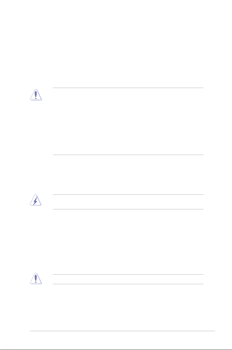
1.2.1 Placement direction
When installing the motherboard, ensure that you place it into the chassis in the correct
orientation. The edge with external ports goes to the rear part of the chassis as indicated in
the image below.
1.2.2 Screw holes
Place six screws into the holes indicated by circles to secure the motherboard to the chassis.
Do not overtighten the screws! Doing so can damage the motherboard.
ASUS B75M-PLUS
1-1
Place this side towards
B75M-PLUS
PCIEX16
PCIEX1_1
PCI1
F_PANEL
SPEAKER
CLRTC
SPDIF_OUT
LPT
USBPWF
KB_USBPWB
USB56 USB78
AAFP
ATX12V
EATXPWR
CPU_FAN
CHA_FAN
BATTERY
Super
I/O
ALC
887
RTL
8111G
DIGI
+VRM
8MB
BIOS
SB_PWR
22.6cm(8.9in)
LGA1155
Intel
®
B75
DDR3 DIMM_A1 (64bit, 240-pin module)
DDR3 DIMM_A2 (64bit, 240-pin module)
DDR3 DIMM_B1 (64bit, 240-pin module)
DDR3 DIMM_B2 (64bit, 240-pin module)
SATA3G_4
SATA3G_5
SATA6G_1 SATA3G_1 SATA3G_2
SATA3G_3
AUDIO
KBMS
LAN1_USB12
USB3_12
USB34
HDMI
19.8cm(7.8in)
DVI_VGA
COM
USB3_34
432 31 5
1
10 9612 1113141516
17
6
7
8
18
the rear of the chassis
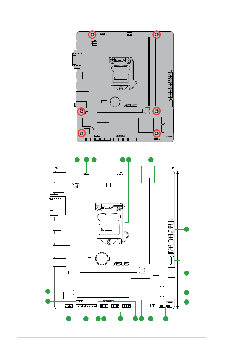
1.2.3 Motherboard layout
Chapter 1: Product introduction
1-2
1.2.4 Layout contents
B75M-PLUS
B75M-PLUS CPU socket LGA1155
Connectors/Jumpers/Slots/LED Page
1. ATX power connectors (24-pin EATXPWR, 4-pin ATX12V) 1-15
2. Keyboard and USB device wake-up (KB_USBPWB) 1-12
3. CPU and chassis fan connectors (4-pin CPU_FAN, 4-pin CHA_FAN) 1-16
4. Intel® LGA1155 CPU socket 1-3
5. DDR3 DIMM slots 1-7
6. Intel® B75 Serial ATA 3.0Gb/s connectors (7-pin SATA3G_1~5 [blue]) 1-18
7. Intel® B75 Serial ATA 6.0Gb/s connector (7-pin SATA6G_1 [gray]) 1-18
8. Speaker connector (4-pin SPEAKER) 1-17
9. USB 3.0 connector (20-1 pin USB3_34) 1-19
10. System panel connector (10-1 pin F_PANEL) 1-17
11. USB device wake-up (USBPWF) 1-12
12. USB 2.0 connectors (10-1 pin USB56, USB78) 1-19
13. Serial port connectors (10-1 pin COM) 1-20
14. Clear RTC RAM (3-pin CLRTC) 1-11
15. LPT connector (26-1 pin LPT) 1-21
16. Front panel audio connector (10-1 pin AAFP) 1-15
17. Digital audio connector (4-1 pin SPDIF_OUT) 1-20
18. Onboard LED (SB_PWR) 1-21
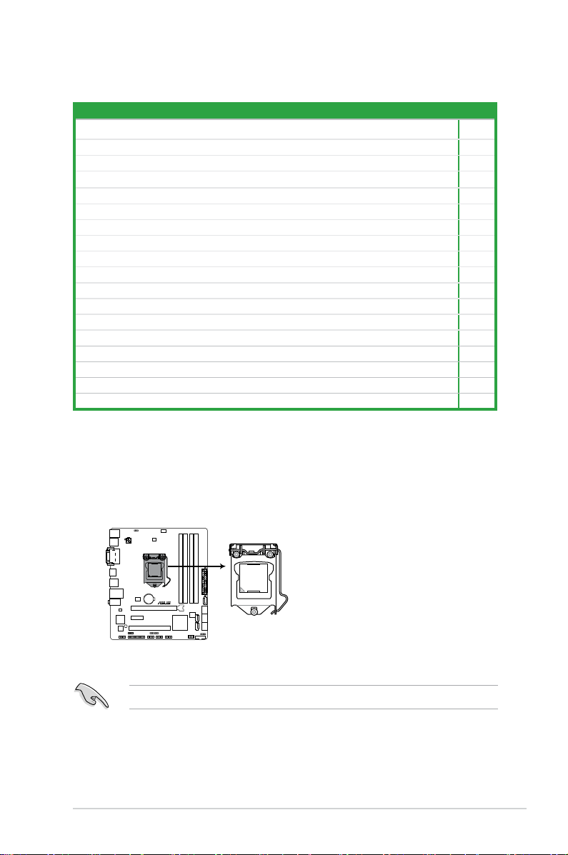
1.3 Central Processing Unit (CPU)
This motherboard comes with a surface mount LGA1155 socket designed for the Intel
3rd/2nd generation Core™ i7 / Core™ i5 / Core™ i3 / Pentium® / Celeron® processors.
Unplug all power cables before installing the CPU.
ASUS B75M-PLUS
1-3
• Upon purchase of the motherboard, ensure that the PnP cap is on the socket and
the socket contacts are not bent. Contact your retailer immediately if the PnP cap
is missing, or if you see any damage to the PnP cap/socket contacts/motherboard
components. ASUS will shoulder the cost of repair only if the damage is shipment/
transit-related.
• Keep the cap after installing the motherboard. ASUS will process Return Merchandise
Authorization (RMA) requests only if the motherboard comes with the cap on the
LGA1155 socket.
• The product warranty does not cover damage to the socket contacts resulting from
incorrect CPU installation/removal, or misplacement/loss/incorrect removal of the PnP
cap.
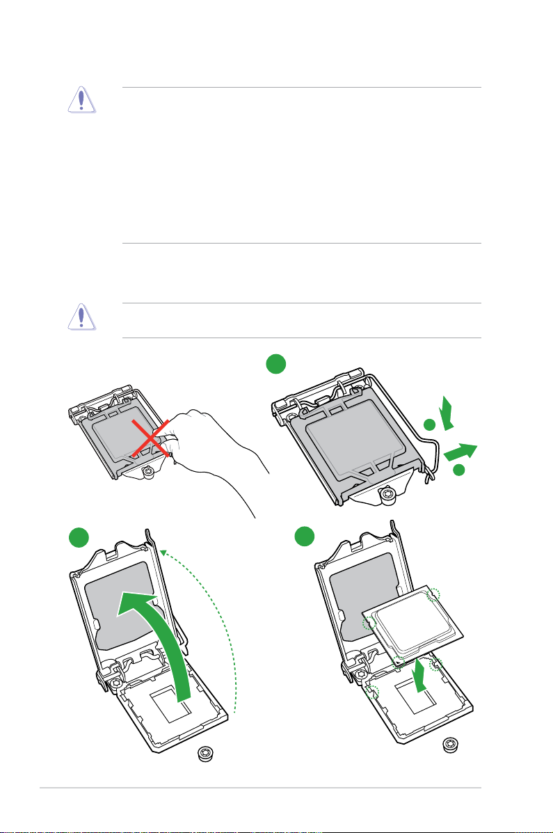
1.3.1 Installing the CPU
The LGA1156 CPU is incompatible with the LGA1155 socket. DO NOT install a LGA1156
CPU on the LGA1155 socket.
1
1-4
2
3
Chapter 1: Product introduction
4
5
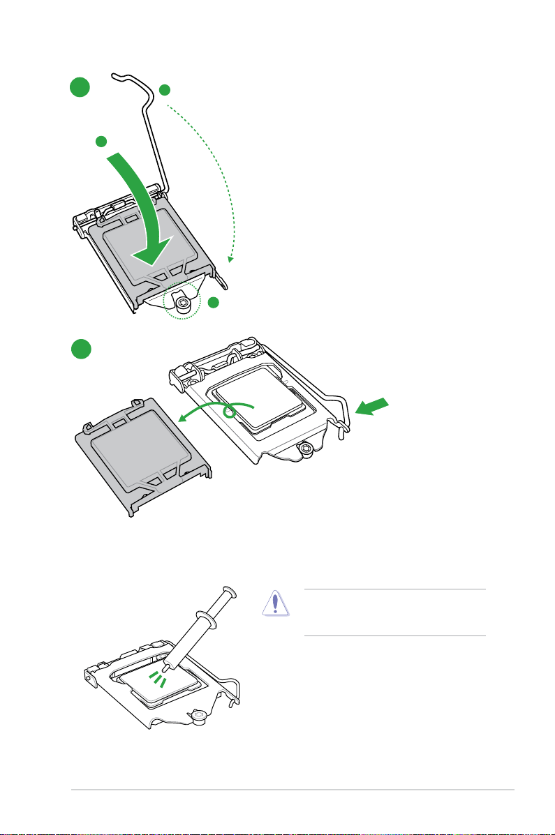
1.3.2 CPU heatsink and fan assembly installation
ASUS B75M-PLUS
Apply the Thermal Interface Material to the
CPU heatsink and CPU before you install the
heatsink and fan if necessary.
1-5
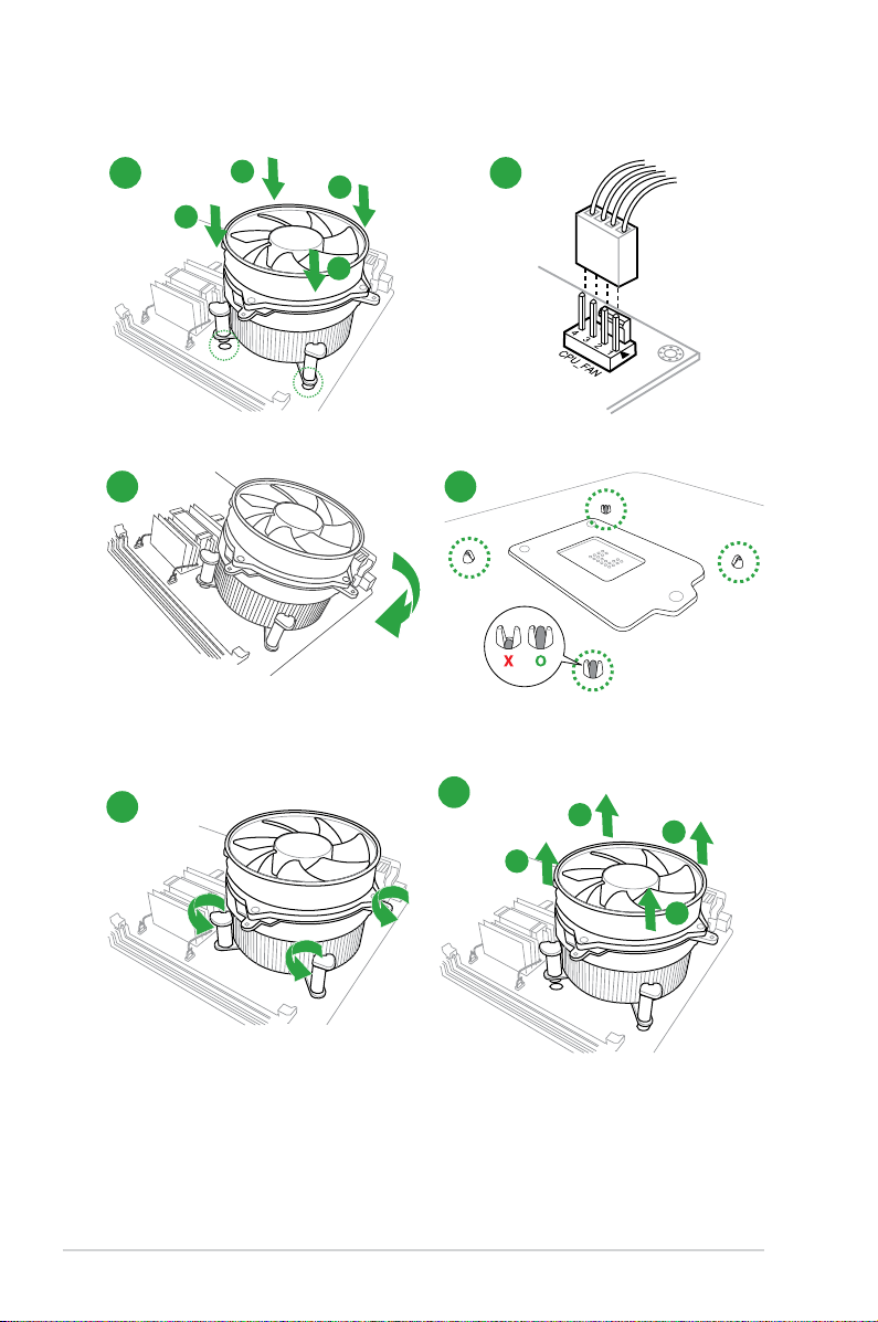
To install the CPU heatsink and fan assembly
1
A
B
B
A
3
2
4
To uninstall the CPU heatsink and fan assembly
1
2
B
A
B
1-6
A
Chapter 1: Product introduction
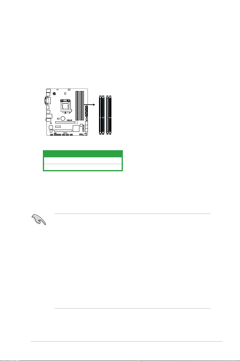
1.4 System memory
DIMM_A1
DIMM_A2
DIMM_B1
DIMM_B2
B75M-PLUS
B75M-PLUS 240-pin DDR3 DIMM sockets
1.4.1 Overview
This motherboard comes with two Double Data Rate 3 (DDR3) Dual Inline Memory Module
(DIMM) sockets. A DDR3 module has the same physical dimensions as a DDR2 DIMM but
is notched differently to prevent installation on a DDR2 DIMM socket. DDR3 modules are
developed for better performance with less power consumption. The gure illustrates the
location of the DDR3 DIMM sockets:
Channel Sockets
Channel A DIMM_A1 and DIMM_A2
Channel B DIMM_B1 and DIMM_B2
1.4.2 Memory congurations
You may install 1GB, 2GB, 4GB, and 8GB unbuffered non-ECC DDR3 DIMMs into the DIMM
sockets.
• You may install varying memory sizes in Channel A and Channel B. The system maps
the total size of the lower-sized channel for the dual-channel conguration. Any excess
memory from the higher-sized channel is then mapped for single-channel operation.
• According to Intel CP specication, DIMM voltage below 1.65V is is recommended to
protect the CPU.
• Always install DIMMs with the same CAS latency. For optimal compatibility, we
recommend that you install memory modules of the same version or date code (D/C)
from the same vendor. Check with the retailer to get the correct memory modules.
• Due to the memory address limitation on 32-bit Windows
or more memory on the motherboard, the actual usable memory for the OS can be
about 3GB or less. For effective use of memory, we recommend that you do any of the
following:
— Use a maximum of 3GB system memory if you are using a 32-bit Windows
— Install a 64-bit Windows
motherboard.
ASUS B75M-PLUS
®
OS, when you install 4GB
®
OS if you want to install 4GB or more on the
®
OS.
1-7
• For more details, refer to the Microsoft® support site at http://support.microsoft.com/
kb/929605/en-us
• This motherboard does not support DIMMs made up of 512 megabits (Mb) chips or
less.
• Memory modules with memory frequency higher than 2133 MHz and its corresponding
timing or the loaded X.M.P. Prole is not the JEDEC memory standard. The stability
and compatibility of these memory modules depend on the CPU’s capabilities and
other installed devices.
• The maximum 32GB memory capacity can be supported with 8GB or above DIMMs.
ASUS will update the memory QVL once the DIMMs are available in the market.
• The default memory operation frequency is dependent on its Serial Presence Detect
(SPD), which is the standard way of accessing information from a memory module.
Under the default state, some memory modules for overclocking may operate at a
lower frequency than the vendor-marked value. To operate at the vendor-marked
or at a higher frequency, refer to section 2.4 Ai Tweaker menu for manual memory
frequency adjustment.
• For system stability, use a more efcient memory cooling system to support a full
memory load (4 DIMMs) or overclocking condition.
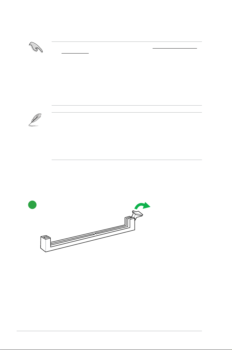
1.4.3 Installing a DIMM
1
1-8
Chapter 1: Product introduction
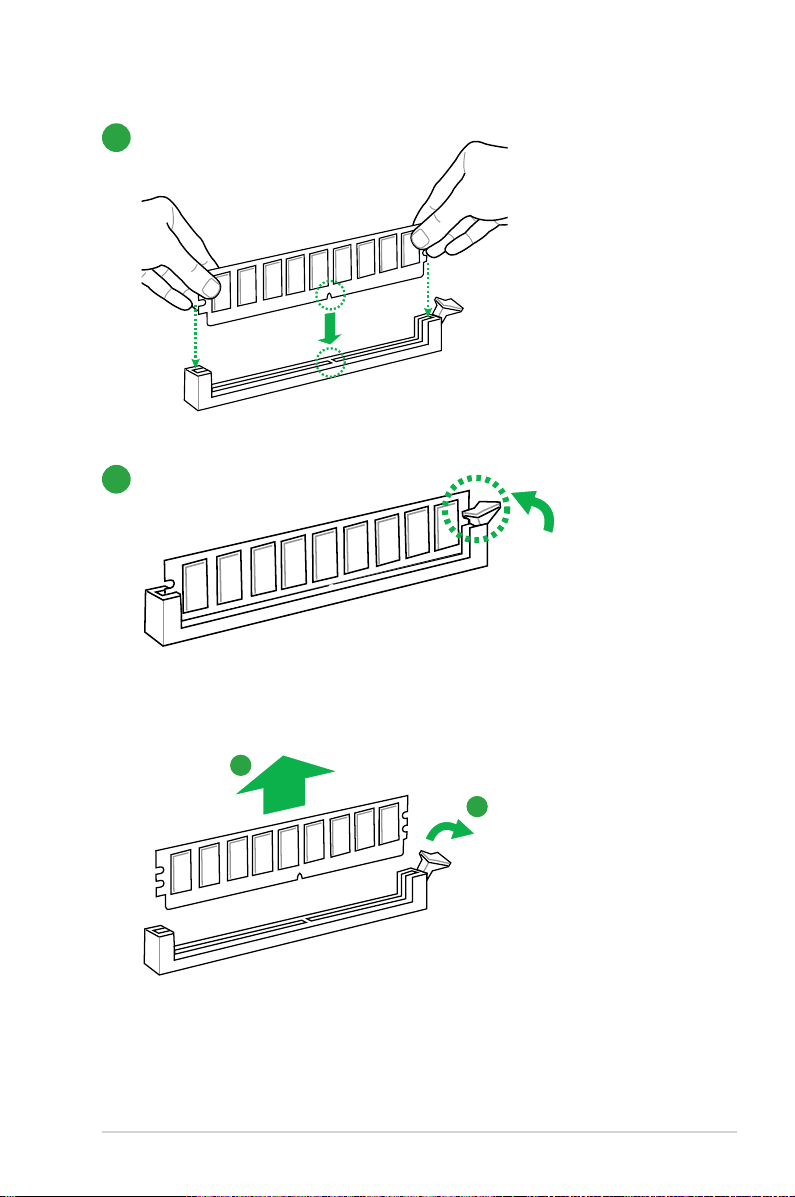
2
3
To remove a DIMM
ASUS B75M-PLUS
B
A
1-9
1.5 Expansion slots
In the future, you may need to install expansion cards. The following sub-sections describe
the slots and the expansion cards that they support.
Unplug the power cord before adding or removing expansion cards. Failure to do so may
cause you physical injury and damage motherboard components.
1.5.1 Installing an expansion card
To install an expansion card:
1. Before installing the expansion card, read the documentation that came with it and
make the necessary hardware settings for the card.
2. Remove the system unit cover (if your motherboard is already installed in a chassis).
3. Remove the bracket opposite the slot that you intend to use. Keep the screw for later
use.
4. Align the card connector with the slot and press rmly until the card is completely
seated on the slot.
5. Secure the card to the chassis with the screw you removed earlier.
6. Replace the system cover.
1.5.2 Conguring an expansion card
After installing the expansion card, congure it by adjusting the software settings.
1. Turn on the system and change the necessary BIOS settings, if any. See Chapter 2 for
information on BIOS setup.
2. Assign an IRQ to the card.
3. Install the software drivers for the expansion card.
When using PCI cards on shared slots, ensure that the drivers support “Share IRQ” or that
the cards do not need IRQ assignments. Otherwise, conicts will arise between the two PCI
groups, making the system unstable and the card inoperable.
1.5.3 PCI slot
The PCI slot supports cards such as a LAN card, SCSI card, USB card, and other cards that
comply with PCI specications.
1.5.4 PCI Express 2.0 x1 slot
This motherboard supports PCI Express 2.0 network cards, SCSI cards, and other cards that
comply with the PCI Express specications.
1-10
Chapter 1: Product introduction

1.5.5 PCI Express 3.0/2.0 x1 slot
B75M-PLUS
B75M-PLUS Clear RTC RAM
1 2
2 3
Normal
(Default)
Clear RTC
CLRTC
This motherboard supports one PCI Express 3.0/2.0 graphics card that comply with the PCI
Express specications.
Intel® 3rd Generation Core processors support PCIe 3.0.
IRQ assignments for this motherboard
A B C D E F G H
Intel PCH SATA controller #0 — — — shared — — — —
Intel PCH SATA controller #1 — — — shared — — — Realtek 8111G controller shared — — — — — — —
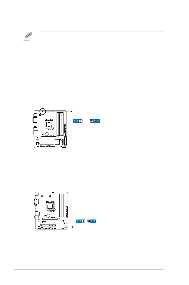
1.6 Jumpers
Clear RTC RAM (3-pin CLRTC)
This jumper allows you to clear the Real Time Clock (RTC) RAM in CMOS. You can
clear the CMOS memory of date, time, and system setup parameters by erasing
the CMOS RTC RAM data. The onboard button cell battery powers the RAM data in
CMOS, which include system setup information such as system passwords.
To erase the RTC RAM:
1. Turn OFF the computer and unplug the power cord.
2. Move the jumper cap from pins 1-2 (default) to pins 2-3. Keep the cap on pins 2-3
for about 5-10 seconds, then move the cap back to pins 1-2.
3. Plug the power cord and turn ON the computer.
4. Hold down the <
enter data.
Except when clearing the RTC RAM, never remove the cap on CLRTC jumper default
position. Removing the cap will cause system boot failure!
ASUS B75M-PLUS
Del> key during the boot process and enter BIOS setup to re-
1-11
• If the steps above do not help, remove the onboard battery and move the jumper
B75M-PLUS
+5V +5VSB
(Default)
KB_USBPWB
B75M-PLUS Keyboard and USB device wake up
1 2
2 3
B75M-PLUS
21
2 3
+5V
(Default)
+5VSB
USBPWF
B75M-PLUS USB device wake up
again to clear the CMOS RTC RAM data. After clearing the CMOS, reinstall the
battery.
• You do not need to clear the RTC when the system hangs due to overclocking. For
system failure due to overclocking, use the CPU Parameter Recall (C.P.R.) feature.
Shut down and reboot the system, then the BIOS automatically resets parameter
settings to default values.
2. Keyboard and USB device wake-up (KB_USBPWB)
This jumper allows you to enable or disable the P/S 2 device wake-up feature. When
you set this jumper to pins 2-3 (+5VSB), you can wake up the computer by pressing a
key on the P/S 2 keyboard or by clicking on the P/S 2 mouse. This feature requires an
ATX power supply that can supply at least 1A on the +5VSB lead, and a corresponding
setting in the BIOS.
3. USB device wake-up (USBPWF)
Set this jumper to +5V to wake up the computer from S1 sleep mode (CPU stopped,
DRAM refreshed, system running in low power mode) using the connected USB
devices. Set to +5VSB to wake up from S3 and S4 sleep modes (no power to CPU,
DRAM in slow refresh, power supply in reduced power mode).
1-12
Chapter 1: Product introduction
• The USB device wake-up feature requires a power supply that can provide 500mA on
the +5VSB lead for each USB port; otherwise, the system would not power up.
• The total current consumed must NOT exceed the power supply capability (+5VSB)
whether under normal condition or in sleep mode.
1.7 Connectors
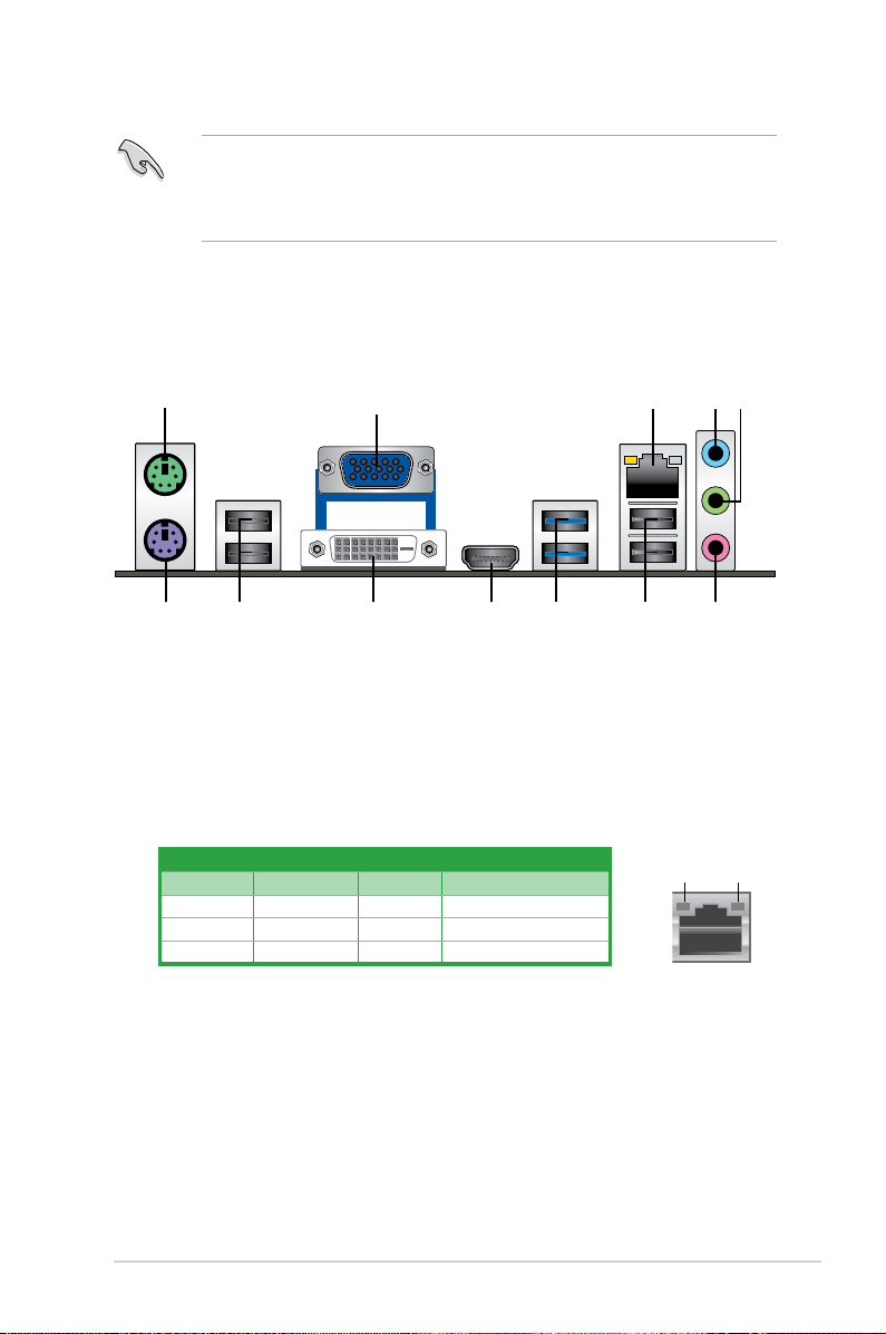
1.7.1 Rear panel connectors
1. PS/2 mouse port. This port is for a PS/2 mouse.
2. Video Graphics Adapter (VGA) port.
VGA-compatible devices.
3. LAN (RJ-45) port.
This port allows Gigabit connection to a Local Area Network (LAN)
through a network hub.
LAN port LED indications
This 15-pin port is for a VGA monitor or other
Activity/Link LED Speed LED
Status Description Status Description
OFF No link OFF 10Mbps connection
ORANGE Linked ORANGE 100Mbps connection
BLINKING Data activity GREEN 1Gbps connection
4. Line In port (light blue).
This port connects to the tape, CD, DVD player, or other
Activity Link
LED
audio sources.
5. Line Out port (lime).
8-channel congurations, the function of this port becomes Front Speaker Out.
6. Microphone port (pink)
This port connects to a headphone or a speaker. In the 4, 6 and
. This port connects to a microphone.
ASUS B75M-PLUS
LAN port
Speed
LED
1-13
 Loading…
В представленном списке руководства для конкретной модели Материнской платы — ASUS B75M-PLUS. Вы можете скачать инструкции к себе на компьютер или просмотреть онлайн на страницах сайта бесплатно или распечатать.
- Инструкции и файлы
- Характеристики
- Основные поломки
- Сервисы по ремонту
В случае если инструкция на русском не полная или нужна дополнительная информация по этому устройству, если вам нужны
дополнительные файлы: драйвера, дополнительное руководство пользователя (производители зачастую для каждого
продукта делают несколько различных документов технической помощи и руководств), свежая версия прошивки, то
вы можете задать вопрос администраторам или всем пользователям сайта, все постараются оперативно отреагировать
на ваш запрос и как можно быстрее помочь. Ваше устройство имеет характеристики:Socket: LGA1155, Поддерживаемые процессоры: Intel Core i7/Core i5/Core i3, Поддержка многоядерных процессоров: есть, Чипсет: Intel B75, BIOS: AMI, Поддержка SLI/CrossFire: нет, полные характеристики смотрите в следующей вкладке.
Для многих товаров, для работы с ASUS B75M-PLUS могут понадобиться различные дополнительные файлы: драйвера, патчи, обновления, программы установки. Вы можете скачать онлайн эти файлы для конкретнй модели ASUS B75M-PLUS или добавить свои для бесплатного скачивания другим посетителями.
Если вы не нашли файлов и документов для этой модели то можете посмотреть интсрукции для похожих товаров и моделей, так как они зачастую отличаются небольшим изменениями и взаимодополняемы.
Обязательно напишите несколько слов о преобретенном вами товаре, чтобы каждый мог ознакомиться с вашим отзывом или вопросом. Проявляйте активность что как можно бльше людей смогли узнать мнение настоящих людей которые уже пользовались ASUS B75M-PLUS.
Александр
2018-04-24 15:19:43
Хорошая плата
Алексей
2018-07-16 16:54:51
Крутая материнская плата!
Никита
2018-07-21 16:08:06
Хорошая материнка
Денчик
2018-10-11 13:19:08
Ща узнаю
Денчик
2018-10-11 13:19:54
Ща узнаю
SkyDrive
2019-01-29 10:08:37
Хорошая карта
Максим
2019-04-30 22:34:02
Отличная
Михаил
2019-07-06 12:39:18
Круто
Николай
2019-07-26 10:36:57
Пять лет — полёт нормальный
Михаил
2019-07-30 21:30:08
Карта
Михаил
2019-07-30 21:31:05
Карта
Гребнев Михаил
2019-11-12 00:05:04
отличная
роман
2020-01-29 17:25:10
норм
Основные и самые важные характеристики модели собраны из надежных источников и по характеристикам можно найти похожие модели.
| Процессор | |
| Socket | LGA1155 |
| Поддерживаемые процессоры | Intel Core i7/Core i5/Core i3 |
| Поддержка многоядерных процессоров | есть |
| Чипсет | |
| Чипсет | Intel B75 |
| BIOS | AMI |
| Поддержка SLI/CrossFire | нет |
| Память | |
| Память | DDR3 DIMM, 1066 — 2200 МГц |
| Количество слотов памяти | 4 |
| Поддержка двухканального режима | есть |
| Максимальный объем памяти | 32 Гб |
| Дисковые контроллеры | |
| IDE | нет |
| SATA | количество разъемов SATA 3Gb/s: 5, количество разъемов SATA 6Gb/s: 1 |
| Слоты расширения | |
| Слоты расширения | 1xPCI-E x16, 1xPCI-E x1, 1xPCI |
| Поддержка PCI Express 2.0 | есть |
| Поддержка PCI Express 3.0 | есть |
| Аудио/видео | |
| Звук | 7.1CH, HDA, на основе Realtek ALC887 |
| Сеть | |
| Ethernet | 1000 Мбит/с, на основе Realtek 8111G, |
| Подключение | |
| Наличие интерфейсов | 12 USB, из них 4 USB 3.0 (2 на задней панели), выход S/PDIF, 1xCOM, D-Sub, DVI, HDMI, Ethernet, PS/2 (клавиатура), PS/2 (мышь), LPT |
| Разъемы на задней панели | 6 USB, из них 2 USB 3.0, D-Sub, DVI, HDMI, Ethernet, PS/2 (клавиатура), PS/2 (мышь) |
| Основной разъем питания | 24-pin |
| Разъем питания процессора | 4-pin |
| Тип системы охлаждения | пассивное |
| Дополнительные параметры | |
| Форм-фактор | microATX |
Здесь представлен список самых частых и распространенных поломок и неисправностей у Материнских плат. Если у вас такая поломка то вам повезло, это типовая неисправность для ASUS B75M-PLUS и вы можете задать вопрос о том как ее устранить и вам быстро ответят или же прочитайте в вопросах и ответах ниже.
| Название поломки | Описание поломки | Действие |
|---|---|---|
| Разрыв Печатных Проводников | ||
| Обрыв Конденсаторов Или Резисторов | ||
| Короткое Замыкание В Электрических Цепях | ||
| Разрушение Разъемов И Слотов | ||
| Поломка Процессорного Разъема | ||
| Выгорание Портов | ||
| Микротрещины В Плате | ||
| Выход Из Строя Сетевого Адаптера | ||
| Перегрев Компонентов | ||
| Не Запускается При Включении | При Включении Не Загружается. В Биос Не Входит. Пост Код — А3 | |
| Какой Компонент | Подскажите Марку Траyзистора Q46? | |
| Не Работает Ps/2 | Сначала Отвалилась Клавиатура, А Через Некоторое Время 6 Коротких Гудков И Не Запускается | |
| Подключить Переднюю Панель | Не Могу Подключить Переднюю Панель | |
| Судя По Всему Отвал Биоса | Материнка Стартует Секунд На 5,Кулер Процессора Берет Обороты И Останавливается.и Так-Циклически,Без Остановок.запуск Невозможен.вечером Либо Завтра Буду Пытаться Его Восстановить,Потом Может Дополню | |
| Пропал Звук На Материнке | Пропал Звук На Материнке, Отображается Только Nvidia Hdmi. Переустановка Драйверов С Офсайта Не Помогла. | |
| Биос | При Старте Звук Через Промежетки Времени Примерно В 1-3 Мин Три Сигнала Потом Стартует Винда , Недавно Вообще Написал Cmos Setting Wrong И C7, Жму Del Меняется На B2 Чтоб Воити В Биос Три Сигнала По Одному Через Промеежутки Времени 1-3 Мин И Черный Экра | |
| Asus M2A-Vm Hdmi | Не Запускается Процессор Phenom Ii X4 945 Rev. C3, На Socket-Ам 3, Нет Даже Сигнала, Черный Экран | |
| Не Включается | После Замены Конденсаторов С34 И С35 Не Включается | |
| Черный Экран | Все Уже Перепробовал И Озу Менял И Переставлял И Ластиком Чистил, И Батарейку Вынимал И Измерял, И Видеокарту С Бп На Заведомо Годную Ставил Исход Один, Черный Экран И Speaker Издает 1 Длинный 2 Коротких, Если Я Не Путаю. | |
| Неправильно Отображается Память | При Установленной Памяти 4 Гигабайта В Биосе Отображается 8. Установил Одну Планку 2 Гига — Отображается 4 | |
В нашей базе сейчас зарегестрированно 18 353 сервиса в 513 города России, Беларусии, Казахстана и Украины.

КОМПЬЮТЕРНЫЙ СЕРВИС NOTE1ST
⭐
⭐
⭐
⭐
⭐
Адресс:
Cущевский вал, д. 5, стр.12 оф.№Б-30
Телефон:
74955174562
Сайт:
n/a
Время работы
Время работы не указано
ASUS
⭐
⭐
⭐
⭐
⭐
Адресс:
Зеленый проспект, д.81
Телефон:
74999630187
Сайт:
n/a
Время работы
Время работы не указано
RSS
⭐
⭐
⭐
⭐
⭐
Адресс:
1-й Гончарный пер., д. 4, стр. 3
Телефон:
74952762211
Сайт:
n/a
Время работы
Будни: с 0900 до 2100
Суббота: с 1000 до 1800
Воскресенье: выходной
РАКЕТА
⭐
⭐
⭐
⭐
⭐
Адресс:
Авиамоторная 20/17
Телефон:
79153657000
Сайт:
n/a
Время работы
Будни: с 0900 до 1900
Суббота: с 1200 до 1600
Воскресенье: выходной
МАСТЕРСКАЯ РЕМОНТОЗАВР
⭐
⭐
⭐
⭐
⭐
Адресс:
ул.Октябрьская дом 17/18
Телефон:
79653003111
Сайт:
n/a
Время работы
Будни: с 0900 до 1900
Суббота: с 1000 до 1800
Воскресенье: с 1000 до 1800
Материнская плата ASUS B75M-PLUS | unboxing
1:08
Очень доволен
хочу
авпваы
Хочу купить
ирлдоьвап ькеьпрлджыкеь дзьакерджь щзрбкежбрь апкыезрбкыеджрбеджр щзапбкерл
Только приобрела,а инструкции нет
Только приобрела,а инструкции нет
Отвалился распрыскиватель