
A88XM-PLUS

Регистрация устройства поможет вам управлять его гарантией, получать техническую поддержку и отслеживать статус ремонта.
Регистрация продукта
Руководства пользователя
- Руководства пользователя
- Декларация соответствия
Версия E10276
91.95 KB
HDMI insert (English)
Версия F8561
6.66 MB
A88XM-PLUS user’s manual(French)
Версия E8561
5.17 MB
A88XM-PLUS User’s Manual (English)
Версия T8561
4.46 MB
A88XM-PLUS User’s Manual(Traditional Chinese)
Версия C8561
4.58 MB
A88XM-PLUS User’s Manual (Simplified Chinese)
Версия J8561
4.13 MB
A88XM-PLUS User’s Manual (Japanese)
-
Page 1
A88XM-PLUS… -
Page 2
Product warranty or service will not be extended if: (1) the product is repaired, modified or altered, unless such repair, modification of alteration is authorized in writing by ASUS; or (2) the serial number of the product is defaced or missing. -
Page 3: Table Of Contents
Contents Safety information ………………iv About this guide ………………iv Package contents ………………vi A88XM-PLUS specifications summary …………. vi Product introduction Before you proceed …………..1-1 Motherboard overview …………..1-2 Accelerated Processing Unit (APU) ……….. 1-4 System memory …………….1-8 Expansion slots …………….
-
Page 4: Safety Information
Safety information Electrical safety • To prevent electrical shock hazard, disconnect the power cable from the electrical outlet before relocating the system. • When adding or removing devices to or from the system, ensure that the power cables for the devices are unplugged before the signal cables are connected. If possible, disconnect all power cables from the existing system before you add a device.
-
Page 5
Refer to the following sources for additional information and for product and software updates. ASUS websites The ASUS website provides updated information on ASUS hardware and software products. Refer to the ASUS contact information. Optional documentation Your product package may include optional documentation, such as warranty flyers, that may have been added by your dealer. -
Page 6: Package Contents
APUs. • The maximum 64GB memory capacity can be supported with 16GB or above DIMMs. ASUS will update the memory QVL once the DIMMs are available in the market. • Refer to www.asus.com for the latest Memory QVL (Qualified Vendors List).
-
Page 7
— ASUS MemOK! — ASUS AI Suite 3 — ASUS AI Charger — ASUS Anti Surge — ASUS UEFI BIOS EZ Mode featuring a friendly graphical user interface — ASUS Network iControl* — ASUS USB 3.0 Boost — ASUS Disk Unlocker… -
Page 8
BIOS features 64 Mb Flash ROM, UEFI AMI BIOS, PnP, DMI 2.0, WfM 2.0, SM BIOS 2.7, ACPI 2.0a, Multi-language BIOS, ASUS EZ Flash 2, ASUS CrashFreen BIOS 3, F12 Printscreen function, F3 Shortcut function and ASUS DRAM SPD (Serial Presence Detect) memory information… -
Page 9
A88XM-PLUS specifications summary Operating System Windows 8 / 8 64-bit ® Windows 7 / 7 64-bit ® Windows ® Support DVD Drivers ASUS utilities ASUS Update Anti-virus software (OEM version) Form factor uATX form factor: 9.6 in x 9.2 in (24.4 cm x 23.4 cm) -
Page 11: Product Introduction
ON, in sleep mode, or in soft-off mode. This is a reminder that you should shut down the system and unplug the power cable before removing or plugging in any motherboard component. The illustration below shows the location of the onboard LED. SB_PWR A88XM-PLUS Standby Power Powered Off A88XM-PLUS Onboard LED ASUS A88XM-PLUS…
-
Page 12: Motherboard Overview
Place six screws into the holes indicated by circles to secure the motherboard to the chassis. Do not overtighten the screws! Doing so can damage the motherboard. Place this side towards the rear of the chassis A88XM-PLUS Chapter 1: Product introduction…
-
Page 13
CHA_FAN2 CPU_FAN DIGI +VRM HDMI ATX12V MemOK! DRAM_LED USB34 USB3_12 LAN_USB12 CHA_FAN1 A88XM-PLUS AUDIO PCIEX16_1 8111G PCIEX1_1 BATTERY Super ® A88X PCI1 SPEAKER SB_PWR PCIEX16_2 887-VD2 BIOS CLRTC F_PANEL CHASSIS SPDIF_OUT SATA6G_1 SATA6G_2 SATA6G_3 USB910 USB78 USB56 USB3_34 AAFP ASUS A88XM-PLUS… -
Page 14: Accelerated Processing Unit (Apu)
Ensure that you use an APU designed for the FM2+ socket. The APU fits in only one correct orientation. DO NOT force the APU into the socket to prevent bending the pins and damaging the APU! A88XM-PLUS A88XM-PLUS CPU socket FM2+ Chapter 1: Product introduction…
-
Page 15
1.3.1 APU installation ASUS A88XM-PLUS… -
Page 16
1.3.2 APU heatsink and fan assembly installation Apply the Thermal Interface Material to the APU heatsink and APU before you install the heatsink and fan if necessary. To install the APU heatsink and fan assembly Chapter 1: Product introduction… -
Page 17
To uninstall the APU heatsink and fan assembly ASUS A88XM-PLUS… -
Page 18: System Memory
Sockets Channel A DIMM_A1 and DIMM_A2 Channel B DIMM_B1 and DIMM_B2 A88XM-PLUS A88XM-PLUS 240-pin DDR3 DIMM sockets 1.4.2 Memory configurations You may install 1GB, 2GB, 4GB, and 8GB unbuffered non-ECC DDR3 DIMMs into the DIMM sockets. • You may install varying memory sizes in Channel A and Channel B. The system maps the total size of the lower-sized channel for the dual-channel configuration.
-
Page 19
• For system stability, use a more efficient memory cooling system to support a full memory load (4 DIMMs) or overclocking condition. • Visit the ASUS website at: www.asus.com for the latest QVL. 1.4.3 Installing a DIMM ASUS A88XM-PLUS… -
Page 20: Expansion Slots
To remove a DIMM Expansion slots In the future, you may need to install expansion cards. The following sub-sections describe the slots and the expansion cards that they support. Unplug the power cord before adding or removing expansion cards. Failure to do so may cause you physical injury and damage motherboard components.
-
Page 21
– On Chip USB XHCI 1 – – shared – – – – – On Chip USB XHCI 2 – shared – – – – – – HD Audio shared – – – – – – – ASUS A88XM-PLUS 1-11… -
Page 22: Jumpers
A88XM-PLUS Normal Clear RTC (Default) A88XM-PLUS Clear RTC RAM To erase the RTC RAM: Turn OFF the computer and unplug the power cord. Move the jumper cap from pins 1-2 (default) to pins 2-3. Keep the cap on pins 2-3 for about 5-10 seconds, then move the cap back to pins 1-2.
-
Page 23
By default, the pins labeled “Intruder” are shorted with a jumper cap. Remove the jumper caps only when you intend to use the chassis intrusion detection feature. CHASSIS A88XM-PLUS PIN 1 A88XM-PLUS Chassis intrusion connector ASUS A88XM-PLUS 1-13… -
Page 24: Onboard Switches
If the installed DIMMs still fail to boot after the whole tuning process, the DRAM_LED lights continuously. Replace the DIMMs with ones recommended in the Memory QVL (Qualified Vendors Lists) in this user manual or on the ASUS website at www.asus.com.
-
Page 25: Onboard Leds
GPU Boost switch This switch allows you to enable or disable the GPU Boost function. GPU Boost A88XM-PLUS A88XM-PLUS GPU Boost switch Onboard LEDs DRAM LED DRAM LED checks the DRAM in sequence during motherboard booting process. If an error is found, the LED next to the error device will continue lighting up until the problem is solved.
-
Page 26: Connectors
Connectors 1.9.1 Rear panel connectors PS/2 mouse port. This port is for a PS/2 mouse. Video Graphics Adapter (VGA) port. This 15-pin port is for a VGA monitor or other VGA-compatible devices. LAN (RJ-45) port. This port allows Gigabit connection to a Local Area Network (LAN) through a network hub.
-
Page 27
RGB Signal to CRT and isn’t compatible with DVI-I. HDMI port. This port is for a High-Definition Multimedia Interface (HDMI) connector, and is HDCP compliant allowing playback of HD DVD, Blu-ray, and other protected content. PS/2 keyboard port. This port is for a PS/2 keyboard. ASUS A88XM-PLUS 1-17… -
Page 28
These are not jumpers! DO NOT place jumper caps on the fan connectors. • The CPU_FAN connector supports a CPU fan of maximum 2A (24W) fan power. • Only the 4-pin CPU_FAN supports the ASUS Fan Xpert2 feature. Chapter 1: Product introduction 1-18… -
Page 29
The system may become unstable or may not boot up if the power is inadequate. • If you are uncertain about the minimum power supply requirement for your system, refer to the Recommended Power Supply Wattage Calculator at http://support.asus. com/PowerSupplyCalculator/PSCalculator.aspx?SLanguage=en-us for details. ASUS A88XM-PLUS 1-19… -
Page 30
RAID 0, RAID 1, RAID 10 and JBOD configuration through the onboard controller. A88XM-PLUS A88XM-PLUS SATA 6.0Gb/s connectors • These connectors are set to AHCI mode by default. If you intend to create a Serial ATA RAID set using these connectors, set the type of the SATA connectors in the BIOS to [RAID]. -
Page 31
PIN 1 A88XM-PLUS +HDD_LED RESET A88XM-PLUS System panel connector • System power LED (2-pin PLED) This 2-pin connector is for the system power LED. Connect the chassis power LED cable to this connector. The system power LED lights up when you turn on the system power, and blinks when the system is in sleep mode. -
Page 32
A88XM-PLUS HD-audio-compliant Legacy AC’97 pin definition compliant definition A88XM-PLUS Front panel audio connector • We recommend that you connect a high-definition front panel audio module to this connector to avail of the motherboard high-definition audio capability. • If you want to connect a high definition front panel audio module to this connector, set the Front Panel Type item in the BIOS to [HD]. -
Page 33
USB-chargeable devices, optimized power efficiency and backward compatibility with USB 2.0. USB3_34 PIN 1 A88XM-PLUS A88XM-PLUS USB3.0 Front panel connector You can connect the ASUS front panel USB 3.0 bracket to this connector to obtain the front panel USB 3.0 solution. ASUS A88XM-PLUS 1-23… -
Page 34
PIN 1 A88XM-PLUS A88XM-PLUS Serial port (COM) connector The COM module is purchased separately. TPM connector (20-1 pin TPM) This connector supports a Trusted Platform Module (TPM) system, which can securely store keys, digital certificates, passwords and data. -
Page 35
LPT connector (26-1 pin LPT) The LPT (Line Printing Terminal) connector supports devices such as a printer. LPT is standardized as IEEE 1284, which is the parallel port interface on IBM PC-compatible computers. A88XM-PLUS A88XM-PLUS Parallel Port Connector ASUS A88XM-PLUS 1-25… -
Page 36: Software Support
The contents of the Support DVD are subject to change at any time without notice. Visit the ASUS website at www.asus.com for updates. To run the Support DVD Place the Support DVD into the optical drive.
-
Page 37: Bios Information
Managing and updating your BIOS Save a copy of the original motherboard BIOS file to a USB flash disk in case you need to restore the BIOS in the future. Copy the original motherboard BIOS using the ASUS Update utility.
-
Page 38
2.1.2 ASUS EZ Flash 2 The ASUS EZ Flash 2 feature allows you to update the BIOS without using an OS-based utility. Before you start using this utility, download the latest BIOS file from the ASUS website at www.asus.com. To update the BIOS using EZ Flash 2: Insert the USB flash disk that contains the latest BIOS file to the USB port. -
Page 39
2.1.3 ASUS CrashFree BIOS 3 utility The ASUS CrashFree BIOS 3 is an auto recovery tool that allows you to restore the BIOS file when it fails or gets corrupted during the updating process. You can restore a corrupted BIOS file using the motherboard support DVD or a USB flash drive that contains the updated BIOS file. -
Page 40
Insert the DOS-bootable USB flash drive with the latest BIOS file and BIOS Updater to your computer’s USB port. Boot your computer. When the ASUS Logo appears, press <F8> to show the BIOS Boot Device Select Menu. Select the USB flash drive as the boot device. The DOS screen appears. -
Page 41
Ensure to load the BIOS default settings to ensure system compatibility and stability. Select the Load Optimized Defaults item under the Exit menu. Refer to section 2.10 Exit menu for details. • Ensure to connect all SATA hard disk drives after updating the BIOS file if you have disconnected them. ASUS A88XM-PLUS… -
Page 42: Bios Setup Program
BIOS setup program Use the BIOS Setup program to update the BIOS or configure its parameters. The BIOS screens include navigation keys and brief online help to guide you in using the BIOS Setup program. Entering BIOS Setup at startup To enter BIOS Setup at startup: •…
-
Page 43
The Advanced Mode provides advanced options for experienced end-users to configure the BIOS settings. The figure below shows an example of the Advanced Mode. Refer to the following sections for the detailed configurations. To access the EZ Mode, click Exit, then select ASUS EZ Mode. ASUS A88XM-PLUS… -
Page 44
Back button Menu items Menu bar Configuration fields General help Last modified Navigation keys settings Quick Scroll bar note Menu bar The menu bar on top of the screen has the following main items: My Favorites For saving the frequently-used system settings and configuration Main For changing the basic system configuration Ai Tweaker… -
Page 45: My Favorites
This button allows you to enter notes of the activities that you have done in BIOS. Last Modified button This button shows the items that you last modified and saved in BIOS Setup. My Favorites MyFavorites is your personal space where you can easily save and access your favorite BIOS items. ASUS A88XM-PLUS…
-
Page 46: Main Menu
Adding items to My Favorites To add frequently-used BIOS items to My Favorites: Use the arrow keys to select an item that you want to add. When using a mouse, hover the pointer to the item. Press <F4> on your keyboard or right-click on your mouse to add the item to My Favorites page.
-
Page 47
To clear the user password, follow the same steps as in changing a user password, but press <Enter> when prompted to create/confirm the password. After you clear the password, the User Password item on top of the screen shows Not Installed. ASUS A88XM-PLUS 2-11… -
Page 48: Ai Tweaker Menu
Ai Tweaker menu The Ai Tweaker menu items allow you to configure overclocking-related items. Be cautious when changing the settings of the Ai Tweaker menu items. Incorrect field values can cause the system to malfunction. The configuration options for this section vary depending on the CPU and DIMM model you installed on the motherboard.
-
Page 49
This item appears only when The EPU Power Saving Mode is set to [Enabled] and allows you to set power saving mode. Configuration options: [Auto] [Light Power Saving Mode] [Medium Power Saving Mode] [Max Power Saving Mode] ASUS A88XM-PLUS 2-13… -
Page 50
2.5.6 GPU Boost [Auto] [Auto] Automatic configuration. [Turbo Mode] Set to [Turbo Mode] to achieve better 3D performance. [Extreme Mode] Set to [Extreme Mode] for the excellent visual experience. [Manual Mode] Set to [Manual Mode] if you want to manually select the desired GPU Engine frequency. -
Page 51
[Regular] [High] [Extreme] CPU Current Capability [100%] This item provides wider total power range for overclocking. A higher value brings a wider total power range and extends the overclocking frequency range simultaneously. Configuration options: [100%] [110%] [120%] [130%] ASUS A88XM-PLUS 2-15… -
Page 52
Reducing phase number under light system loading to increase VRM efficiency. [Standard] Proceeds phase control depending on the CPU loading. [Optimized] Loads the ASUS optimized phase tuning profile. [Extreme] Proceeds the full phase mode. [Manual Adjustment] Allows manual adjustment. -
Page 53: Advanced Menu
Disables the CPB (Core Performance Boost) mode or set it to [Auto] for automatic configuration. Configuration options: [Disabled] [Auto] C6 Mode [Enabled] Enables or disables C6 mode. Configuration options: [Enabled] [Disabled] IOMMU [Disabled] Set this item to [Enabled] to show IOMMU Mode. Configuration options: [Enabled] [Disabled] ASUS A88XM-PLUS 2-17…
-
Page 54
Bank Interleaving [Enabled] Enables or disables the bank memory interleaving. Configuration options: [Enabled] [Disabled] Channel Interleaving [Enabled] Enables or disables the channel memory interleaving. Configuration options: [Enabled] [Disabled] Core Leveling Mode [Automatic mode] Allows you to change the number of working Compute Unit on the system. Configuration options: [Automatic mode] [One core per processor] [One Compute Unit] [One core per Compute Unit] 2.6.2… -
Page 55
USB support is disabled. EHCI Hand-off [Disabled] [Enabled] Enables the support for operating systems without an EHCI hand-off feature. [Disabled] Disables the function. USB Single Port Control Allows you to enable/disable individual USB ports. ASUS A88XM-PLUS 2-19… -
Page 56
2.6.4 NB Configuration IGFX Multi-Monitor [Disabled] Enables or disables the Internal Graphics Device Multi-Monitor support for add-on VGA devices. And the memory size of Internal Graphics Device will keep memory reserved. Configuration options: [Disabled] [Enabled] The IGFX Multi-Monitor item must be enabled before using AMD Dual Graphics ®… -
Page 57
[Disabled] Change Settings [IO=3F8h; IRQ=4] This item appears only when you set the Serial Port to [Enabled] and allows you to select the Serial Port base address. Configuration options: [IO=3F8h; IRQ=4] [IO=2F8h; IRQ=3] [IO=3E8h; IRQ=4] [IO=2E8h; IRQ=3] ASUS A88XM-PLUS 2-21… -
Page 58
Parallel Port Configuration The sub-items in this menu allow you to set the parallel port configuration. Parallel Port [Enabled] Allows you to enable or disable the parallel port (LPT/LPTE). Configuration options: [Enabled] [Disabled] The following items appear only when you set the Parallel Port Configuration item to [Enabled]. -
Page 59
This item allows user to disable or enable the Ipv4 PXE Boot support. Configuration options: [Disabled] [Enable] Ipv6 PXE Support [Enabled] This item allows user to disable or enable the Ipv6 PXE Boot support. Configuration options: [Disabled] [Enabled] ASUS A88XM-PLUS 2-23… -
Page 60: Monitor Menu
Monitor menu The Monitor menu displays the system temperature/power status, and allows you to change the fan settings. Scroll down to display the following items: 2-24 Chapter 2: BIOS information…
-
Page 61
Use the <+> and <-> keys to adjust the maximum CPU fan duty cycle. The values range from 0% to 100%. When the CPU temperature reaches the upper limit, the CPU fan will operate at the maximum duty cycle. ASUS A88XM-PLUS 2-25… -
Page 62
CPU Q-Fan Lower Temperature [20] Use the <+> and <-> keys to adjust the lower limit of the CPU temperature. The values range from 20ºC to 75ºC. CPU Q-Fan Min. Duty Cycle(%) [20] Use the <+> and <-> keys to adjust the minimum CPU fan duty cycle. The values range from 0% to 100%. -
Page 63: Boot Menu
This item allows you to enable or disable the Anti Surge function. Configuration options: [Auto] [Disabled] [Enabled] Boot menu The Boot menu items allow you to change the system boot options. Scroll down to display the following items: ASUS A88XM-PLUS 2-27…
-
Page 64
2.8.1 Fast Boot [Enabled] [Enabled] Select to accelerate the boot speed. [Disabled] Select to go back to normal boot. The following four items appear when you set Fast Boot to [Enabled]. SATA Support [All Devices] [All Devices] All devices connected to SATA ports will be available during POST. -
Page 65
The third-party ROM messages will be displayed only if the third-party manufacturer had set the add-on device to do so. 2.8.6 Interrupt 19 Capture [Disabled] [Enabled] Allows the option ROMs to trap Interrupt 19. [Disabled] Disables this function. ASUS A88XM-PLUS 2-29… -
Page 66
2.8.7 Setup Mode [EZ Mode] [Advanced Mode] Sets Advanced Mode as the default screen for entering the BIOS setup program. [EZ Mode] Sets EZ Mode as the default screen for entering the BIOS setup program. 2.8.8 CSM (Compatibility Support Module) Allows you to configure the CSM (Compatibility Support Module) items to fully support the various VGA, bootable devices and add-on devices for better compatibility. -
Page 67
Secure Boot keys will not be active. Configuration options: [Yes] [No] Load PK from File Allows you to load the downloaded PK from a USB storage device. The PK file must be formatted as a UEFI variable structure with time-based authenticated variable. ASUS A88XM-PLUS 2-31… -
Page 68
KEK Management The KEK (Key-exchange Key or Key Enrollment Key) manages the Signature database (db) and Revoked Signature database (dbx). Key-exchange Key (KEK) refers to Microsoft Secure Boot Key-Enrollment Key (KEK). ® Delete the KEK Allows you to delete the KEK from your system. Configuration options: [Yes] [No] Load KEK from File Allows you to load the downloaded KEK from a USB storage device. -
Page 69
• To select the boot device during system startup, press <F8> when ASUS Logo appears. • To access Windows OS in Safe Mode, press <F8> after POST. -
Page 70: Tools Menu
<Enter> to display the submenu. 2.9.1 ASUS EZ Flash 2 Utility Allows you to run ASUS EZ Flash 2. Press [Enter] to launch the ASUS EZ Flash 2 screen. For more details, see section 2.1.2 ASUS EZ Flash 2. 2.9.2…
-
Page 71: Exit Menu
This option allows you to exit the Setup program without saving your changes. When you select this option or if you press <Esc>, a confirmation window appears. Select Yes to discard changes and exit. ASUS EZ Mode This option allows you to enter the EZ Mode screen. Launch EFI Shell from filesystem device This option allows you to attempt to launch the UEFI Shell application (shellx64.efi) from one…
-
Page 72
2-36 Chapter 2: BIOS information… -
Page 73: Appendices
Cet appareil est conforme aux normes CNR exemptes de licence d’Industrie Canada. Le fonctionnement est soumis aux deux conditions suivantes : (1) cet appareil ne doit pas provoquer d’interférences et (2) cet appareil doit accepter toute interférence, y compris celles susceptibles de provoquer un fonctionnement non souhaité de l’appareil. ASUS A88XM-PLUS…
-
Page 74
ASUS Recycling/Takeback Services ASUS recycling and takeback programs come from our commitment to the highest standards for protecting our environment. We believe in providing solutions for you to be able to responsibly recycle our products, batteries, other components as well as the packaging materials. -
Page 75: Asus Contact Information
+1-812-282-3777 +1-510-608-4555 Web site usa.asus.com Technical Support Telephone +1-812-282-2787 Support fax +1-812-284-0883 Online support support.asus.com ASUS COMPUTER GmbH (Germany and Austria) Address Harkort Str. 21-23, D-40880 Ratingen, Germany +49-2102-959911 Web site www.asus.de Online contact www.asus.de/sales Technical Support Telephone +49-1805-010923* Support Fax…
-
Page 76
Appendices…
-
Драйверы
47
-
Инструкции по эксплуатации
5
Языки:

ASUS A88XM-PLUS инструкция по эксплуатации
(76 страниц)
- Языки:Английский
-
Тип:
PDF -
Размер:
5.17 MB -
Описание:
A88XM-PLUS User’s Manual (English)
Просмотр

ASUS A88XM-PLUS инструкция по эксплуатации
(76 страниц)
- Языки:Японский
-
Тип:
PDF -
Размер:
4.13 MB -
Описание:
A88XM-PLUS User’s Manual (Japanese)
Просмотр

ASUS A88XM-PLUS инструкция по эксплуатации
(74 страницы)
- Языки:Китайский
-
Тип:
PDF -
Размер:
4.58 MB -
Описание:
A88XM-PLUS User’s Manual (Simplified Chinese)
Просмотр

ASUS A88XM-PLUS инструкция по эксплуатации
(72 страницы)
- Языки:Китайский
-
Тип:
PDF -
Размер:
4.46 MB -
Описание:
A88XM-PLUS User’s Manual(Traditional Chinese)
Просмотр

ASUS A88XM-PLUS инструкция по эксплуатации
(74 страницы)
- Языки:Французский
-
Тип:
PDF -
Размер:
6.66 MB -
Описание:
A88XM-PLUS user’s manual(French)
Просмотр
На NoDevice можно скачать инструкцию по эксплуатации для ASUS A88XM-PLUS. Руководство пользователя необходимо для ознакомления с правилами установки и эксплуатации ASUS A88XM-PLUS. Инструкции по использованию помогут правильно настроить ASUS A88XM-PLUS, исправить ошибки и выявить неполадки.
- Инструкции и руководства
- Бренды
- ASUS
- A88XM-PLUS
- Справочник Пользователя
![]()
![]()
A88XM-PLUSMotherboard

E8561
First Edition
August 2013
Copyright © 2013 ASUSTeK COMPUTER INC. All Rights Reserved.
No part of this manual, including the products and software described in it, may be reproduced, transmitted, transcribed, stored in a retrieval system, or translated into any language in any form or by any means, except documentation kept by the purchaser for backup purposes, without the express written permission of ASUSTeK COMPUTER INC. (“ASUS”).
Product warranty or service will not be extended if: (1) the product is repaired, modified or altered, unless such repair, modification of alteration is authorized in writing byASUS; or (2) the serial number of the product is defaced or missing.
ASUS PROVIDES THIS MANUAL “AS IS” WITHOUT WARRANTY OF ANY KIND, EITHER EXPRESS OR IMPLIED, INCLUDING BUT NOT LIMITED TO THE IMPLIED WARRANTIES OR CONDITIONS OF MERCHANTABILITY OR FITNESS FOR A PARTICULAR PURPOSE. IN NO EVENT SHALL ASUS, ITS DIRECTORS, OFFICERS, EMPLOYEES OR AGENTS BE LIABLE FOR ANY INDIRECT, SPECIAL, INCIDENTAL, OR CONSEQUENTIAL DAMAGES (INCLUDING DAMAGES FOR LOSS OF PROFITS, LOSS OF BUSINESS, LOSS OF USE OR DATA, INTERRUPTION OF BUSINESS AND THE LIKE), EVEN IF ASUS HAS BEEN ADVISED OF THE POSSIBILITY OF SUCH DAMAGES ARISING FROM ANY DEFECT OR ERROR IN THIS MANUAL OR PRODUCT.
SPECIFICATIONS AND INFORMATION CONTAINED IN THIS MANUAL ARE FURNISHED FOR INFORMATIONAL USE ONLY, AND ARE SUBJECT TO CHANGE AT ANY TIME WITHOUT NOTICE, AND SHOULD NOT BE CONSTRUED AS A COMMITMENT BY ASUS. ASUS ASSUMES NO RESPONSIBILITY OR LIABILITY FOR ANY ERRORS OR INACCURACIES THAT MAY APPEAR IN THIS MANUAL, INCLUDING THE PRODUCTS AND SOFTWARE DESCRIBED IN IT.
Products and corporate names appearing in this manual may or may not be registered trademarks or copyrights of their respective companies, and are used only for identification or explanation and to the owners’ benefit, without intent to infringe.
Offer to Provide Source Code of Certain Software
This product contains copyrighted software that is licensed under the General Public License (“GPL”), under the Lesser General Public License Version (“LGPL”) and/or other Free Open Source Software Licenses. Such software in this product is distributed without any warranty to the extent permitted by the applicable law. Copies of these licenses are included in this product.
Where the applicable license entitles you to the source code of such software and/or other additional data, you may obtain it for a period of three years after our last shipment of the product, either
(1)for free by downloading it from http://support.asus.com/download
or
(2)for the cost of reproduction and shipment, which is dependent on the preferred carrier and the location where you want to have it shipped to, by sending a request to:
ASUSTeK Computer Inc.
Legal Compliance Dept.
15 Li Te Rd.,
Beitou, Taipei 112
Taiwan
In your request please provide the name, model number and version, as stated in the About Box of the product for which you wish to obtain the corresponding source code and your contact details so that we can coordinate the terms and cost of shipment with you.
The source code will be distributed WITHOUT ANY WARRANTY and licensed under the same license as the corresponding binary/object code.
This offer is valid to anyone in receipt of this information.
ASUSTeK is eager to duly provide complete source code as required under various Free Open Source Software licenses. If however you encounter any problems in obtaining the full corresponding source code we would be much obliged if you give us a notification to the email address gpl@asus.com, stating the product and describing the problem (please DO NOT send large attachments such as source code archives, etc. to this email address).
ii

Contents
|
Safety information…………………………………………………………………………… |
iv |
|
About this guide……………………………………………………………………………… |
iv |
|
Package contents……………………………………………………………………………. |
vi |
|
A88XM-PLUS specifications summary……………………………………………… |
vi |
Product introduction
|
1.1 |
Before you proceed……………………………………………………………. |
1-1 |
|
1.2 |
Motherboard overview……………………………………………………….. |
1-2 |
|
1.3 |
Accelerated Processing Unit (APU)…………………………………….. |
1-4 |
|
1.4 |
System memory…………………………………………………………………. |
1-8 |
|
1.5 |
Expansion slots……………………………………………………………….. |
1-10 |
|
1.6 |
Jumpers…………………………………………………………………………… |
1-12 |
|
1.7 |
Onboard switches…………………………………………………………….. |
1-14 |
|
1.8 |
Onboard LEDs………………………………………………………………….. |
1-15 |
|
1.9 |
Connectors………………………………………………………………………. |
1-16 |
|
1.10 |
Software support……………………………………………………………… |
1-26 |
BIOS information
|
2.1 |
Managing and updating your BIOS……………………………………… |
2-1 |
|
2.2 |
BIOS setup program…………………………………………………………… |
2-6 |
|
2.3 |
My Favorites………………………………………………………………………. |
2-9 |
|
2.4 |
Main menu……………………………………………………………………….. |
2-10 |
|
2.5 |
Ai Tweaker menu……………………………………………………………… |
2-12 |
|
2.6 |
Advanced menu……………………………………………………………….. |
2-17 |
|
2.7 |
Monitor menu…………………………………………………………………… |
2-24 |
|
2.8 |
Boot menu……………………………………………………………………….. |
2-27 |
|
2.9 |
Tools menu………………………………………………………………………. |
2-34 |
|
2.10 |
Exit menu…………………………………………………………………………. |
2-35 |
Appendices
|
Notices…………………………………………………………………………………………. |
A-1 |
|
ASUS contact information……………………………………………………………… |
A-3 |
iii

Safety information
Electrical safety
•To prevent electrical shock hazard, disconnect the power cable from the electrical outlet before relocating the system.
•When adding or removing devices to or from the system, ensure that the power cables for the devices are unplugged before the signal cables are connected. If possible, disconnect all power cables from the existing system before you add a device.
•Before connecting or removing signal cables from the motherboard, ensure that all power cables are unplugged.
•Seek professional assistance before using an adapter or extension cord. These devices could interrupt the grounding circuit.
•Ensure that your power supply is set to the correct voltage in your area. If you are not sure about the voltage of the electrical outlet you are using, contact your local power company.
•If the power supply is broken, do not try to fix it by yourself. Contact a qualified service technician or your retailer.
Operation safety
•Before installing the motherboard and adding components, carefully read all the manuals that came with the package.
•Before using the product, ensure all cables are correctly connected and the power cables are not damaged. If you detect any damage, contact your dealer immediately.
•To avoid short circuits, keep paper clips, screws, and staples away from connectors, slots, sockets and circuitry.
•Avoid dust, humidity, and temperature extremes. Do not place the product in any area where it may be exposed to moisture.
•Place the product on a stable surface.
•If you encounter technical problems with the product, contact a qualified service technician or your retailer.
About this guide
This user guide contains the information you need when installing and configuring the motherboard.
How this guide is organized
This guide contains the following parts:
•Chapter 1: Product introduction
This chapter describes the features of the motherboard and the new technology it supports. It includes descriptions of the switches, jumpers, and connectors on the motherboard.
•Chapter 2: BIOS information
This chapter discusses changing system settings through the BIOS Setup menus. Detailed descriptions fo the BIOS parameters are also provided.
iv

Where to find more information
Refer to the following sources for additional information and for product and software updates.
1.ASUS websites
The ASUS website provides updated information on ASUS hardware and software products. Refer to the ASUS contact information.
2.Optional documentation
Your product package may include optional documentation, such as warranty flyers, that may have been added by your dealer. These documents are not part of the standard package.
Conventions used in this guide
To ensure that you perform certain tasks properly, take note of the following symbols used throughout this manual.
DANGER/WARNING: Information to prevent injury to yourself when completing a task.
CAUTION: Information to prevent damage to the components when completing a task
IMPORTANT: Instructions that you MUST follow to complete a task.
NOTE: Tips and additional information to help you complete a task.
Typography
|
Bold text |
Indicates a menu or an item to select. |
|
Italics |
Used to emphasize a word or a phrase. |
|
<Key> |
Keys enclosed in the less-than and greater-than sign |
|
means that you must press the enclosed key. |
|
|
Example: <Enter> means that you must press the Enter or |
|
|
Return key. |
|
|
<Key1> + <Key2> + <Key3> |
If you must press two or more keys simultaneously, the key |
|
names are linked with a plus sign (+). |

Package contents
Check your motherboard package for the following items.
|
Motherboard |
ASUS A88XM-PLUS motherboard |
|
|
Cables |
2 x Serial ATA 6.0 Gb/s cables |
|
|
Accessories |
1 x I/O Shield |
|
|
Application DVD |
Support DVD |
|
|
Documentation |
User Manual |
|
If any of the above items is damaged or missing, contact your retailer.
A88XM-PLUS specifications summary
|
APU |
AMD® FM2+ socket for AMD® A-Series/Athlon series processors |
|
|
Supports CPU up to 4 cores |
||
|
AMD® Turbo Core Technology 3.0 support |
||
|
• The AMD® Turbo Core Technology 3.0 support depends on the APU types. |
||
|
Chipset |
• Refer to www.asus.com for the AMD® APU support list. |
|
|
AMD® A88X FCH |
||
|
Memory |
4 x 240-pin DIMM slots support maximum 64GB unbuffered non-ECC |
|
|
DDR3 2400(O.C)/2250(O.C.)/2200(O.C.)/2133/1866/1600/1333 MHz |
||
|
memory modules |
||
|
Dual-channel memory architecture |
||
|
SupportsAMD Memory Profile (AMP) memory |
Graphics
Multi-GPU Support Expansion slots
•Hyper DIMM support is subject to the physical characteristics of indivudal APUs.
•The maximum 64GB memory capacity can be supported with 16GB or above DIMMs. ASUS will update the memory QVL once the DIMMs are available in the market.
•Refer to www.asus.com for the latest Memory QVL (Qualified Vendors List).
Integrated AMD Radeon™ HD 8000/7000 Series Graphics in A-Series APU Multi-VGA output support: HDMI, DVI, RGB ports
—Supports HDMI with max. resolution of 4096×2160@24Hz/ 1920×1200@60Hz
—Supports DVI with max. resolution of 2560×1600@60Hz
—Supports RGB with max. resolution of 1920×1600@60Hz
—Maximum shared memory of 2048MB
—Supports AMD® Dual Graphics technology
•Refer to http://www.amd.com/us/products/technologies/dual-graphics/Pages/ dual-graphics.aspx#3 for the discrete GPUs that support Dual Graphics technology.
•Only FM2+ APU can support up to 4096×2160 resolution display via HDMI port.
Supports AMD Quad-GPU CrossFireX™ Technology 1 x PCIe 3.0/2.0 x16 slot*
1 x PCIe 2.0 x16 slot (@x4 mode)
1 x PCI Express 2.0 x1 slot
1 x PCI slot
* Only FM2+ processors can support PCIe 3.0.
(continued on the next page)
vi

A88XM-PLUS specifications summary
|
Storage |
AMD® A88X FCH: |
|
|
— 8 x Serial ATA 6 Gb/s connectors with RAID 0, RAID 1,RAID 5,RAID |
||
|
LAN |
10 and JBOD support |
|
|
Realtek® 8111G PCIe Gigabit LAN controller |
||
|
Audio |
Realtek® ALC887 8-Channel High DefinitionAudio CODEC |
|
|
— Supports Jack-Detection, Multi-Streaming and Front Panel Jack- |
||
|
Retasking |
||
|
• Use a chassis with HD audio module in the front panel to support an 8- |
||
|
USB |
channel audio output. |
|
|
AMD® A88X FCH: |
||
|
— 4 x USB 3.0 ports* (2 ports at the back panel [blue], 2 ports at mid- |
||
|
board) |
||
|
— 10 x USB 2.0 ports (4 ports at the back panel, 6 ports at mid-board) |
||
|
ASUS unique features |
* Supports ASUS USB 3.0 Boost |
|
|
ASUS 5X Protection |
||
|
— ASUS motherboards safeguard your PC with 5X Protection: |
||
|
DIGI+VRM, DRAM Fuse, ESD Guards, High-Quality Solid |
||
|
Capacitors, and Stainless Steel Back I/O to ensure the best quality, |
||
|
reliability, and durability. |
ASUS DIGI+ VRM
—DIGI+ VRM: Digital Power Design for the APU
—DIGI 4+2 Phase Power Design
ASUS DRAM Fuse
—Enhanced DRAM overcurrent protection and short circui damage prevention
ASUS ESD Guard
— Strong ESD Protection for extended component lifespan
ASUS High-Quality Solid Capacitors
— 2.5x Long Lifespan with excellent durability
ASUS Stainless Steel Back I/O
— 3x More durable corrosion-resistant coating
ASUS Exclusive Features
—ASUS EPU
—ASUS GPU Boost
—ASUS TurboV EVO
—ASUS MemOK!
—ASUS AI Suite 3
—ASUS AI Charger
—ASUS Anti Surge
—ASUS UEFI BIOS EZ Mode featuring a friendly graphical user interface
—ASUS Network iControl*
—ASUS USB 3.0 Boost
—ASUS Disk Unlocker
*ASUS Network iControl feature is not supported on Windows® XP/Vista operating systems.
(continued on the next page)
vii

A88XM-PLUS specifications summary
ASUS unique features
Back panel I/O ports
Internal I/O connectors
BIOS features
ASUS Quiet Thermal Solution
—Stylish Fanless Design Heat-sink solution & MOS Heatsink
—ASUS Fan Xpert 2
ASUS EZ DIY
—ASUS CrashFree BIOS 3
—ASUS EZ Flash 2
—ASUS My Logo 2
ASUS Q-Design
— ASUS Q-Slot
1 x PS/2 keyboard port
1 x PS/2 mouse port
1 x HDMI port
1 x DVI port
1 x D-Sub output port
1 x LAN (RJ-45) port
2 x USB 3.0 ports (blue)
4 x USB 2.0/1.1 ports
8-channel audio I/O ports (3 jacks)
1 x USB 3.0 connector supports additional 2 USB 3.0 ports (19-pin) 3 x USB 2.0 connectors support additional 6 USB 2.0 ports
1 x TPM connector
1 x LPT connector
1 x COM Port connector
8 x SATA 6Gb/s connectors
1 x CPU fan connector (4-pin)
2 x Chassis fan connector (4-pin)
1 x S/PDIF Out connector
1 x 24-pin EATX power connector
1 x 4-pin ATX 12V power connector
1 x Front panel audio connector (AAFP)
1 x System panel
1 x MemOK! button
1 x GPU Boost switch
64 Mb Flash ROM, UEFI AMI BIOS, PnP, DMI 2.0, WfM 2.0, SM BIOS 2.7, ACPI 2.0a, Multi-language BIOS, ASUS EZ Flash 2, ASUS
CrashFreen BIOS 3, F12 Printscreen function, F3 Shortcut function and ASUS DRAM SPD (Serial Presence Detect) memory information
(continued on the next page)
viii

A88XM-PLUS specifications summary
Operating System
Support DVD
Form factor
Windows® 8 / 8 64-bit
Windows® 7 / 7 64-bit
Windows® XP
Drivers
ASUS utilities
ASUS Update
Anti-virus software (OEM version)
uATX form factor: 9.6 in x 9.2 in (24.4 cm x 23.4 cm)
Specifications are subject to change without notice.
ix

![]()
Product introduction |
1 |
1.1Before you proceed
Take note of the following precautions before you install motherboard components or change any motherboard settings.
• Unplug the power cord from the wall socket before touching any component.
• Before handling components, use a grounded wrist strap or touch a safely grounded object or a metal object, such as the power supply case, to avoid damaging them due to static electricity.
•Hold components by the edges to avoid touching the ICs on them.
•Whenever you uninstall any component, place it on a grounded antistatic pad or in the bag that came with the component.
•Before you install or remove any component, ensure that the ATX power supply is switched off or the power cord is detached from the power supply. Failure to do so may cause severe damage to the motherboard, peripherals, or components.
Standby Power LED
The motherboard comes with a standby power LED that lights up to indicate that the system is ON, in sleep mode, or in soft-off mode. This is a reminder that you should shut down
the system and unplug the power cable before removing or plugging in any motherboard component. The illustration below shows the location of the onboard LED.
SB_PWR
ON OFF
Standby Power Powered Off
A88XM-PLUS Onboard LED
1.2Motherboard overview
Before you install the motherboard, study the configuration of your chassis to ensure that the motherboard fits.
Unplug the power cord before installing or removing the motherboard. Failure to do so can cause you physical injury and damage to motherboard components.
1.2.1Placement direction
When installing the motherboard, place it into the chassis in the correct orientation. The edge with external ports goes to the rear part of the chassis as indicated in the image.
1.2.2Screw holes
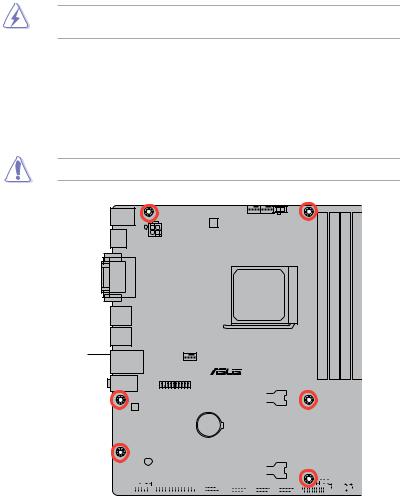
Place six screws into the holes indicated by circles to secure the motherboard to the chassis.
Do not overtighten the screws! Doing so can damage the motherboard.
Place this side towards the rear of the chassis
A88XM-PLUS
|
1-2 |
Chapter 1: Product introduction |

1.2.3Motherboard layout
|
1 |
2 |
3 |
2 |
4 |
5 |
||||||||||||
|
23.4cm(9.2in) |
|||||||||||||||||
|
GPU_Boost |
|||||||||||||||||
|
KBMS |
DIGI |
CHA_FAN2 CPU_FAN GPU_LED |
|||||||||||||||
|
+VRM |
|||||||||||||||||
|
HDMI |
ATX12V |
||||||||||||||||
|
DVI VGA |
FM2+ |
240-pin module) |
240-pin module) |
240-pin module) |
240-pin module) |
MemOK! |
6 |
||||||||||
|
SOCKET |
(64bit,A1DIMMDDR3 |
(64bit,A2DIMMDDR3 |
(64bit,B1DIMMDDR3 |
(64bit,B2DIMMDDR3 |
EATXPWR |
24.4cm(9.6in) |
|||||||||||
|
DRAM_LED |
|||||||||||||||||
|
USB34 |
1 |
||||||||||||||||
|
USB3_12 |
|||||||||||||||||
|
LAN_USB12 |
CHA_FAN1 |
7 |
|||||||||||||||
|
8 |
|||||||||||||||||
|
AUDIO |
A88XM-PLUS |
||||||||||||||||
|
TPM |
SATA6G |
||||||||||||||||
|
PCIEX16_1 |
7 |
||||||||||||||||
|
SATA6G |
|||||||||||||||||
|
RTL |
|||||||||||||||||
|
8111G |
|||||||||||||||||
|
PCIEX1_1 |
BATTERY |
SATA6G 6 |
8 |
||||||||||||||
|
Super |
AMD® |
||||||||||||||||
|
5 |
|||||||||||||||||
|
I/O |
PCI1 |
A88X |
SATA6G |
||||||||||||||
|
SPEAKER |
4 |
||||||||||||||||
|
ALC |
SATA6G |
9 |
|||||||||||||||
|
SB_PWR |
PCIEX16_2 |
8Mb |
|||||||||||||||
|
887-VD2 |
CLRTC |
BIOS |
F_PANEL |
||||||||||||||
|
SPDIF_OUT |
COM |
CHASSIS |
SATA6G_1 |
SATA6G_2 |
SATA6G_3 |
10 |
|||||||||||
|
LPT |
USB910 |
USB78 |
USB56 |
USB3_34 |
|||||||||||||
|
AAFP |
|||||||||||||||||
|
19 18 |
17 |
16 |
15 |
14 |
13 |
12 |
11 |
8 |
1.2.4Layout contents
|
Connectors/Jumpers/Slots/LED |
Page |
|
|
1. |
ATX power connectors (24-pin EATXPWR, 4-pin ATX12V) |
1-19 |
|
2. |
CPU and chassis fan connectors (4-pin CPU_FAN, and 4-pin CHA_FAN) |
1-18 |
|
3. |
AMD FM2+ socket |
1-4 |
|
4. |
GPU Boost switch |
1-15 |
|
5. |
DDR3 DIMM slots |
1-8 |
|
6. |
MemOK! button |
1-14 |
|
7. |
Speaker connector (4-pin SPEAKER) |
1-21 |
|
8. |
SATA 6.0 Gb/s connectors (7-pin SATA6G_1~8) |
1-20 |
|
9. |
System panel connector (10-1 pin F_PANEL) |
1-21 |
|
10. |
Clear RTC RAM (3-pin CLRTC) |
1-12 |
|
11. |
Chassis intrusion connector (4-1 pin CHASSIS) |
1-13 |
|
12. |
USB 3.0 connector (20-1 pin USB3_34) |
1-23 |
|
13. |
USB 2.0 connectors (10-1 pin USB910, USB78, USB56) |
1-23 |
|
14. |
Serial port connector (10-1 pin COM) |
1-24 |
|
15. |
LPT connector (26-1 pin LPT) |
1-25 |
|
16. |
Digital audio connector (4-1 pin SPDIF_OUT) |
1-22 |
|
17. |
Front panel audio connector (10-1 pin AAFP) |
1-22 |
|
18. |
Standby power LED (SB_PWR) |
1-1 |
|
19. |
TPM connector (20-1 pin TPM) |
1-24 |
1.3Accelerated Processing Unit (APU)
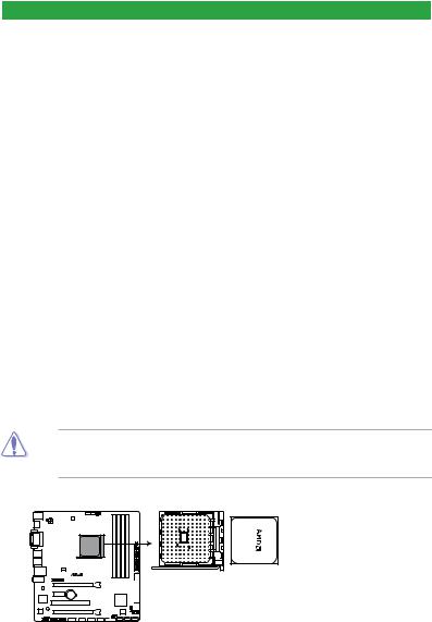
This motherboard comes with a FM2+ socket designed for AMD® A-series and Athlon™ series processors.
Ensure that you use anAPU designed for the FM2+ socket. TheAPU fits in only one correct orientation. DO NOT force the APU into the socket to prevent bending the pins and damaging the APU!
A88XM-PLUS
A88XM-PLUS CPU socket FM2+
|
1-4 |
Chapter 1: Product introduction |


1.3.2APU heatsink and fan assembly installation
Apply the Thermal Interface Material to the APU heatsink and APU before you install the heatsink and fan if necessary.
To install the APU heatsink and fan assembly
|
1-6 |
Chapter 1: Product introduction |

To uninstall the APU heatsink and fan assembly
5

1.4System memory
1.4.1Overview
This motherboard comes with four Double Data Rate 3 (DDR3) Dual Inline Memory Modules (DIMM) sockets.
A DDR3 module has the same physical dimensions as a DDR2 DIMM but is notched differently to prevent installation on a DDR2 DIMM socket. DDR3 modules are developed for better performance with less power consumption.
The figure illustrates the location of the DDR3 DIMM sockets:
|
DIMM A1 DIMM A2 |
DIMM B1 DIMM B2 |
|||||||||||||
A88XM-PLUS
|
Channel |
Sockets |
|
Channel A |
DIMM_A1 and DIMM_A2 |
|
Channel B |
DIMM_B1 and DIMM_B2 |
A88XM-PLUS 240-pin DDR3 DIMM sockets
1.4.2Memory configurations
You may install 1GB, 2GB, 4GB, and 8GB unbuffered non-ECC DDR3 DIMMs into the DIMM sockets.
•You may install varying memory sizes in ChannelAand Channel B. The system maps the total size of the lower-sized channel for the dual-channel configuration.Any excess memory from the higher-sized channel is then mapped for single-channel operation.
•Always install DIMMs with the same CAS latency. For optimal compatibility, we recommend that you install memory modules of the same version or date code (D/C) from the same vendor. Check with the retailer to get the correct memory modules.
•Due to the memory address limitation on 32-bit Windows® OS, when you install 4GB or more memory on the motherboard, the actual usable memory for the OS can be about 3GB or less. For effective use of memory, we recommend that you do any of the following:
—Use a maximum of 3GB system memory if you are using a 32-bit Windows® OS.
—Install a 64-bit Windows® OS if you want to install 4GB or more on the motherboard.
•This motherboard does not support DIMMs made up of 512Mb (64MB) chips or less.
|
1-8 |
Chapter 1: Product introduction |

• The default memory operation frequency is dependent on its Serial Presence Detect (SPD), which is the standard way of accessing information from a memory module. Under the default state, some memory modules for overclocking may operate at a lower frequency than the vendor-marked value. To operate at the vendor-marked
or at a higher frequency, refer to section 2.5 Ai Tweaker menu for manual memory frequency adjustment.
•For system stability, use a more efficient memory cooling system to support a full memory load (4 DIMMs) or overclocking condition.
•Visit the ASUS website at: www.asus.com for the latest QVL.
1.4.3Installing a DIMM
1
2
3
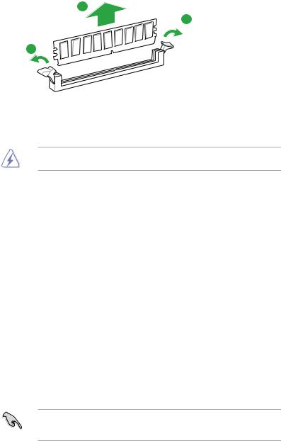
To remove a DIMM
B
A
A
1.5Expansion slots
In the future, you may need to install expansion cards. The following sub sections describe the slots and the expansion cards that they support.
Unplug the power cord before adding or removing expansion cards. Failure to do so may cause you physical injury and damage motherboard components.
1.5.1Installing an expansion card
To install an expansion card:
1.Before installing the expansion card, read the documentation that came with it and make the necessary hardware settings for the card.
2.Remove the system unit cover (if your motherboard is already installed in a chassis).
3.Remove the bracket opposite the slot that you intend to use. Keep the screw for later use.
4.Align the card connector with the slot and press firmly until the card is completely seated on the slot.
5.Secure the card to the chassis with the screw you removed earlier.
6.Replace the system cover.
1.5.2Configuring an expansion card
After installing the expansion card, configure it by adjusting the software settings.
1.Turn on the system and change the necessary BIOS settings, if any. See Chapter 2 for information on BIOS setup.
2.Assign an IRQ to the card.
3.Install the software drivers for the expansion card.
When using PCI cards on shared slots, ensure that the drivers support “Share IRQ” or that the cards do not need IRQ assignments. Otherwise, conflicts will arise between the two PCI groups, making the system unstable and the card inoperable.
|
1-10 |
Chapter 1: Product introduction |
![]()
1.5.3PCI slot
The PCI slot supports cards such as a LAN card, SCSI card, USB card, and other cards that comply with PCI specifications.
1.5.4PCI Express 2.0 x1 slot
This motherboard supports PCI Express x1 network cards, SCSI cards, and other cards that comply with the PCI Express specifications.
1.5.5PCI Express x16 slot
This motherboard supports PCI Express x16 network cards, SCSI cards, and other cards that comply with the PCI Express specifications.
IRQ assignments for this motherboard
|
A |
B |
C |
D |
E |
F |
G |
H |
|
|
PCIEx16_1 |
– |
– |
shared |
– |
– |
– |
– |
– |
|
PCIEx16_2 |
shared |
– |
– |
– |
– |
– |
– |
– |
|
PCIEx1_1 |
shared |
– |
– |
– |
– |
– |
– |
– |
|
PCI 1 |
– |
– |
– |
– |
shared |
– |
– |
– |
|
Realtek 8111G (LAN) |
– |
shared |
– |
– |
– |
– |
– |
– |
|
On Chip SATA |
– |
– |
– |
shared |
– |
– |
– |
– |
|
On Chip USB OHCI 1/2/3/4 |
– |
– |
shared |
– |
– |
– |
– |
– |
|
On Chip USB EHCI 1/2/3 |
– |
shared |
– |
– |
– |
– |
– |
– |
|
On Chip USB XHCI 1 |
– |
– |
shared |
– |
– |
– |
– |
– |
|
On Chip USB XHCI 2 |
– |
shared |
– |
– |
– |
– |
– |
– |
|
HD Audio |
shared |
– |
– |
– |
– |
– |
– |
– |

1.6Jumpers
1.Clear RTC RAM (3-pin CLRTC)
This jumper allows you to clear the Real Time Clock (RTC) RAM in CMOS. You can clear the CMOS memory of date, time, and system setup parameters by erasing the CMOS RTC RAM data. The onboard button cell battery powers the RAM data in CMOS, which include system setup information such as system passwords.
|
CLRTC |
||||
|
A88XM-PLUS |
1 |
2 |
2 |
3 |
|
Normal |
Clear RTC |
|||
|
(Default) |
A88XM-PLUS Clear RTC RAM
To erase the RTC RAM:
1.Turn OFF the computer and unplug the power cord.
2.Move the jumper cap from pins 1-2 (default) to pins 2-3. Keep the cap on pins 2-3 for about 5-10 seconds, then move the cap back to pins 1-2.
3.Plug the power cord and turn ON the computer.
4.Hold down the <Del> key during the boot process and enter BIOS setup to reenter data.
Except when clearing the RTC RAM, never remove the cap on CLRTC jumper default position. Removing the cap will cause system boot failure!
• If the steps above do not help, remove the onboard battery and move the jumper again to clear the CMOS RTC RAM data. After clearing the CMOS, reinstall the battery.
•You do not need to clear the RTC when the system hangs due to overclocking. For system failure due to overclocking, use the CPU Parameter Recall (C.P.R.) feature. Shut down and reboot the system, then the BIOS automatically resets parameter settings to default values.
|
1-12 |
Chapter 1: Product introduction |

2.Chassis intrusion connector (4-1 pin CHASSIS)
This connector is for a chassis-mounted intrusion detection sensor or switch. Connect one end of the chassis intrusion sensor or switch cable to this connector. The chassis intrusion sensor or switch sends a high-level signal to this connector when a chassis component is removed or replaced. The signal is then generated as a chassis intrusion event.
By default, the pins labeled “Intruder” are shorted with a jumper cap. Remove the jumper caps only when you intend to use the chassis intrusion detection feature.
A88XM-PLUS
CHASSIS
|
+5VSB MB |
Chassis Signal GND |
|
PIN 1

A88XM-PLUS Chassis intrusion connector
 Loading…