

105
ASRock B75 Pro3-M Motherboard
Ру
сский
1. Введение
Благодарим вас за покупку материнской платы ASRock B75 Pro3-M надежной материнской
платы, изготовленной в соответствии с постоянно предъявляемыми ASRock жесткими
требованиями к качеству. Она обеспечивает превосходную производительность и
отличается отличной конструкцией, которые отражают приверженность ASRock качеству и
долговечности.
Данное руководство по быстрой установке включает вводную информацию о материнской
плате и пошаговые инструкции по ее установке. Более подробные сведения о плате
можно найти в руководстве пользователя на компакт-диске поддержки.
Спецификации материнской платы и программное обеспечение
BIOS иногда изменяются, поэтому содержание этого руководства
может обновляться без уведомления. В случае любых модификаций
руководства его новая версия будет размещена на веб-сайте ASRock
без специального уведомления. Кроме того, самые свежие списки
поддерживаемых модулей памяти и процессоров можно найти на
сайте ASRock.
Адрес веб-сайта ASRock http://www.asrock.com
При необходимости технической поддержки по вопросам данной
материнской платы посетите наш веб-сайт для получения
информации об используемой модели.
www.asrock.com/support/index.asp
1.1 Комплектность
Материнская плата ASRock B75 Pro3-M
(форм-фактор micro ATX: 9,6 x 9,6 дюйма / 24,4 x 24,4 см)
Руководство по быстрой установке ASRock B75 Pro3-M
Компакт-диск поддержки ASRock B75 Pro3-M
2 x кабель данных Serial ATA (SATA) (дополнительно)
1 x I/O Щит Группы ввода / вывода
ASRock напоминает…
Для обеспечения максимальной производительности ОС Windows
®
7 / 7 64-bit / Vista
TM
/ Vista
TM
64-bit рекомендуется в BIOS выбрать для
параметра Storage Configuration (Конфигурация запоминающего
устройства) режим AHCI. Подробные сведения о настройке BIOS см.
в руководстве пользователя на прилагаемом компакт-диске.
![]()
Copyright Notice:
No part of this installation guide may be reproduced, transcribed, transmitted, or translated in any language, in any form or by any means, except duplication of documentation by the purchaser for backup purpose, without written consent of ASRock Inc.
Products and corporate names appearing in this guide may or may not be registered trademarks or copyrights of their respective companies, and are used only for identification or explanation and to the owners’ benefit, without intent to infringe.
Disclaimer:
Specifications and information contained in this guide are furnished for informational use only and subject to change without notice, and should not be constructed as a commitment by ASRock. ASRock assumes no responsibility for any errors or omissions that may appear in this guide.
With respect to the contents of this guide, ASRock does not provide warranty of any kind, either expressed or implied, including but not limited to the implied warranties or conditions of merchantability or fitness for a particular purpose. In no event shall ASRock, its directors, officers, employees, or agents be liable for any indirect, special, incidental, or consequential damages (including damages for loss of profits, loss of business, loss of data, interruption of business and the like), even if ASRock has been advised of the possibility of such damages arising from any defect or error in the guide or product.
This device complies with Part 15 of the FCC Rules. Operation is subject to the following two conditions:
(1)this device may not cause harmful interference, and
(2)this device must accept any interference received, including interference that may cause undesired operation.
CALIFORNIA, USA ONLY
The Lithium battery adopted on this motherboard contains Perchlorate, a toxic substance controlled in Perchlorate Best Management Practices (BMP) regulations passed by the California Legislature. When you discard the Lithium battery in California, USA, please follow the related regulations in advance.
“Perchlorate Material-special handling may apply, see www.dtsc.ca.gov/hazardouswaste/perchlorate”
ASRock Website: http://www.asrock.com
Published June 2013
Copyright©2013 ASRock INC. All rights reserved.
1
English
ASRock B75 Pro3-M Motherboard
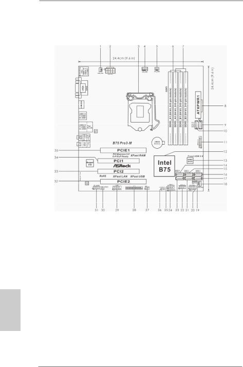
Motherboard Layout
|
1 |
Power Fan Connector (PWR_FAN1) |
19 |
Chassis Speaker Header (SPEAKER1, Black) |
|
2 |
ATX 12V Power Connector (ATX12V1) |
20 |
System Panel Header (PANEL1, Black) |
|
3 |
1155-Pin CPU Socket |
21 |
SATA2 Connector (SATA2_3, Black) |
|
4 |
CPU Fan Connector (CPU_FAN1) |
22 |
USB 2.0 Header (USB10_11, Black) |
|
5 |
CPU Fan Connector (CPU_FAN2) |
23 |
SATA2 Connector (SATA2_1, Black) |
|
6 |
2 x 240-pin DDR3 DIMM Slots |
24 |
Consumer Infrared Module Header |
|
(DDR3_A1, DDR3_B1, Black) |
(CIR1, Gray) |
||
|
7 |
2 x 240-pin DDR3 DIMM Slots |
25 |
USB 2.0 Header (USB8_9, Black) |
|
(DDR3_A2, DDR3_B2, Black) |
26 |
Clear CMOS Jumper (CLRCMOS1) |
|
|
8 |
ATX Power Connector (ATXPWR1) |
27 |
Infrared Module Header (IR1) |
|
9 |
SATA3 Connector (SATA3_A1, Gray) |
28 |
Print Port Header (LPT1) |
|
10 |
SATA3 Connector (SATA3_A0, Gray) |
29 |
COM Port Header (COM1) |
|
11 |
USB 3.0 Header (USB3_2_3, Black) |
30 |
HDMI_SPDIF Header (HDMI_SPDIF1, Black) |
|
12 |
Intel B75 Chipset |
31 |
Front Panel Audio Header |
|
13 |
SPI Flash Memory (64Mb) |
(HD_AUDIO1, Black) |
|
|
14 |
SATA3 Connector (SATA3_0, Gray) |
32 |
PCI Express 2.0 x16 Slot (PCIE2, Black) |
|
15 |
SATA2 Connector (SATA2_2, Black) |
33 |
PCI Slot (PCI2, Black) |
|
16 |
SATA2 Connector (SATA2_4, Black) |
34 |
PCI Slot (PCI1, Black) |
|
17 |
SATA2 Connector (SATA2_5, Black) |
35 |
PCI Express 3.0 x16 Slot (PCIE1, Black) |
|
18 |
Chassis Fan Connector (CHA_FAN1) |
ASRock B75 Pro3-M Motherboard

I/O Panel
|
1 |
USB 2.0 Ports (USB01) |
8 |
Microphone (Pink) |
||
|
2 |
D-Sub Port (VGA1) |
9 |
Optical SPDIF |
Out Port |
|
|
* 3 |
LAN RJ-45 Port |
10 |
USB 2.0 |
Ports |
(USB45) |
|
4 |
Central / Bass (Orange) |
11 |
USB 3.0 |
Ports |
(USB3_01) |
|
5 |
Rear Speaker (Black) |
12 |
HDMI Port (HDMI1) |
||
|
6 |
Line In (Light Blue) |
13 |
DVI-D Port (DVI1) |
||
|
** 7 |
Front Speaker (Lime) |
14 |
PS/2 Keyboard Port (Purple) |
*There is one LED next to the LAN port. Please refer to the table below for the LAN port LED indications.
|
LAN Port LED Indications |
ACT/LINK |
SPEED |
|||||
|
Activity/Link LED |
SPEED LED |
LED |
LED |
||||
|
Status |
Description |
Status |
Description |
||||
|
Off |
No Link |
Off |
10Mbps connection |
||||
|
Blinking |
Data Activity |
Orange |
100Mbps connection |
||||
|
On |
Link |
Green |
1Gbps connection |
LAN Port |
|||
**If you use 2-channel speaker, please connect the speaker’s plug into “Front Speaker Jack”. See the table below for connection details in accordance with the type of speaker you use.
TABLE for Audio Output Connection
|
Audio Output Channels |
Front Speaker |
Rear Speaker |
Central / Bass |
Line in |
|
(No. 7) |
(No. 5) |
(No. 4) |
(No. 6) |
|
|
2 |
V |
— |
— |
— |
|
4 |
V |
V |
— |
— |
|
6 |
V |
V |
V |
— |
|
8 |
V |
V |
V |
V |
ASRock B75 Pro3-M Motherboard

To enable Multi-Streaming function, you need to connect a front panel audio cable to the front panel audio header. After restarting your computer, you will find “Mixer” tool on your system.
Please select “Mixer ToolBox”  , click “Enable playback multi-streaming”, and click
“ok”. Choose “2CH”, “4CH”, “6CH”, or “8CH” and then you are allowed to select “Realtek HDA Primary output” to use Rear Speaker, Central/Bass, and Front Speaker, or select “Realtek HDA Audio 2nd output” to use front panel audio.
English
4
ASRock B75 Pro3-M Motherboard

1. Introduction
Thank you for purchasing ASRock B75 Pro3-M motherboard, a reliable motherboard produced under ASRock’s consistently stringent quality control. It delivers excellent performance with robust design conforming to ASRock’s commitment to quality and endurance.
This Quick Installation Guide contains introduction of the motherboard and step-by- step installation guide. More detailed information of the motherboard can be found in the user manual presented in the Support CD.
Because the motherboard specifications and the BIOS software might be updated, the content of this manual will be subject to change without notice. In case any modifications of this manual occur, the updated version will be available on ASRock website without further notice. You may find the latest VGA cards and CPU support lists on ASRock website as well. ASRock website http://www.asrock.com
If you require technical support related to this motherboard, please visit our website for specific information about the model you are using. www.asrock.com/support/index.asp
1.1 Package Contents
ASRock B75 Pro3-M Motherboard
(Micro ATX Form Factor: 9.6-in x 9.6-in, 24.4 cm x 24.4 cm) ASRock B75 Pro3-M Quick Installation Guide
ASRock B75 Pro3-M Support CD
2 x Serial ATA (SATA) Data Cables (Optional)
1 x I/O Panel Shield
ASRock Reminds You…
To get better performance in Windows® 7 / 7 64-bit / VistaTM / VistaTM 64bit, it is recommended to set the BIOS option in Storage Configuration to
AHCI mode. For the BIOS setup, please refer to the “User Manual” in our support CD for details.
English
5
ASRock B75 Pro3-M Motherboard

1.2 Specifications
|
Platform |
— Micro ATX Form Factor: 9.6-in x 9.6-in, 24.4 cm x 24.4 cm |
|
— All Solid Capacitor design |
|
|
CPU |
— Supports 3rd and 2nd Generation Intel® CoreTM i7 / i5 / i3 in |
|
LGA1155 Package |
|
|
— 4 + 2 Power Phase Design |
|
|
— Supports Intel® Turbo Boost 2.0 Technology |
|
|
— Supports Intel® K-Series unlocked CPU (see CAUTION 1) |
|
|
— Supports Hyper-Threading Technology (see CAUTION 2) |
|
|
— Supports Intel® Rapid Start Technology and Smart Connect |
|
|
Technology with Intel® Ivy Bridge CPU |
|
|
Chipset |
— Intel® B75 |
|
— Supports Intel® Small Business Advantage (see CAUTION 3) |
|
|
Memory |
— Dual Channel DDR3 Memory Technology (see CAUTION 4) |
|
— 4 x DDR3 DIMM slots |
|
|
— Supports DDR3 1600/1333/1066 non-ECC, un-buffered |
|
|
memory (DDR3 1600 with Intel® Ivy Bridge CPU, DDR3 |
|
|
1333 with Intel® Sandy Bridge CPU) |
|
|
— Max. capacity of system memory: 32GB (see CAUTION 5) |
|
|
— Supports Intel® Extreme Memory Profile (XMP)1.3/1.2 |
|
|
Expansion Slot |
— 1 x PCI Express 3.0 x16 slot (PCIE1: x16 mode) |
|
(see CAUTION 6) |
|
|
* PCIE 3.0 is only supported with Intel® Ivy Bridge CPU. With |
|
|
Intel® Sandy Bridge CPU, it only supports PCIE 2.0. |
|
|
— 1 x PCI Express 2.0 x16 slot (PCIE2: x4 mode) |
|
|
— 2 x PCI slots |
|
|
— Supports AMD Quad CrossFireXTM and CrossFireXTM |
|
|
Graphics |
* Intel® HD Graphics Built-in Visuals and the VGA outputs can |
|
be supported only with processors which are GPU |
|
|
integrated. |
|
|
— Supports Intel® HD Graphics Built-in Visuals: Intel® Quick |
|
|
Sync Video 2.0, Intel® InTruTM 3D, Intel® Clear Video HD |
|
|
Technology, Intel® InsiderTM, Intel® HD Graphics 2500/4000 |
|
|
— Pixel Shader 5.0, DirectX 11 with Intel® Ivy Bridge CPU. |
|
|
Pixel Shader 4.1, DirectX 10.1 with Intel® Sandy Bridge CPU |
|
|
— Max. shared memory 1760MB (see CAUTION 7) |
|
|
— Three VGA Output options: D-Sub, DVI-D and HDMI |
|
|
(see CAUTION 8) |
|
|
— Supports HDMI 1.4a Technology with max. resolution up to |
|
|
1920×1200 @ 60Hz |
ASRock B75 Pro3-M Motherboard

|
— Supports DVI with max. resolution up to 1920×1200 @ 60Hz |
||
|
— Supports D-Sub with max. resolution up to 2048×1536 @ |
||
|
75Hz |
||
|
— Supports Auto Lip Sync, Deep Color (12bpc), xvYCC and |
||
|
HBR (High Bit Rate Audio) with HDMI (Compliant HDMI |
||
|
monitor is required) (see CAUTION 9) |
||
|
— Supports HDCP function with DVI and HDMI ports |
||
|
— Supports Full HD 1080p Blu-ray (BD) / HD-DVD playback |
||
|
with DVI and HDMI ports |
||
|
Audio |
— 7.1 CH HD Audio with Content Protection |
|
|
(Realtek ALC892 Audio Codec) |
||
|
— Premium Blu-ray audio support |
||
|
LAN |
— PCIE x1 Gigabit LAN 10/100/1000 Mb/s |
|
|
— Realtek RTL8111E |
||
|
— Supports Wake-On-LAN |
||
|
— Supports LAN Cable Detection |
||
|
— Supports Energy Efficient Ethernet 802.3az |
||
|
— Supports PXE |
||
|
Rear Panel I/O |
I/O Panel |
|
|
— 1 x PS/2 Keyboard Port |
||
|
— 1 x D-Sub Port |
||
|
— 1 x DVI-D Port |
||
|
— 1 x HDMI Port |
||
|
— 1 x Optical SPDIF Out Port |
||
|
— 4 x Ready-to-Use USB 2.0 Ports |
||
|
— 2 x Ready-to-Use USB 3.0 Ports |
||
|
— 1 x RJ-45 LAN Port with LED (ACT/LINK LED and SPEED |
||
|
LED) |
||
|
— HD Audio Jack: Rear Speaker/Central/Bass/Line in/Front |
||
|
Speaker/Microphone (see CAUTION 10) |
||
|
SATA3 |
— 1 x SATA3 6.0 Gb/s connector by Intel® B75, supports NCQ, |
|
|
AHCI and Hot Plug functions |
||
|
— 2 x SATA3 6.0 Gb/s connectors by ASMedia ASM1061, |
||
|
support NCQ, AHCI and Hot Plug functions |
||
|
USB3.0 |
— 2 x Rear USB 3.0 ports, support USB 1.0/2.0/3.0 up to 5Gb/s |
|
|
— 1 x Front USB 3.0 header (supports 2 USB 3.0 ports), |
||
|
supports USB 1.0/2.0/3.0 up to 5Gb/s |
||
|
Connector |
— 5 x SATA2 3.0 Gb/s connectors, support NCQ, AHCI and |
|
|
Hot Plug functions |
||
|
— 3 x SATA3 6.0Gb/s connectors |
||
7
English
ASRock B75 Pro3-M Motherboard

English
|
— 1 x IR header |
|
|
— 1 x CIR header |
|
|
— 1 x Print port header |
|
|
— 1 x COM port header |
|
|
— 1 x HDMI_SPDIF header |
|
|
— CPU/Chassis/Power FAN connector |
|
|
— 24 pin ATX power connector |
|
|
— 8 pin 12V power connector |
|
|
— Front panel audio connector |
|
|
— 2 x USB 2.0 headers (support 4 USB 2.0 ports) |
|
|
— 1 x USB 3.0 header (supports 2 USB 3.0 ports) |
|
|
BIOS Feature |
— 64Mb AMI UEFI Legal BIOS with GUI support |
|
— Supports “Plug and Play” |
|
|
— ACPI 1.1 Compliance Wake Up Events |
|
|
— Supports jumperfree |
|
|
— SMBIOS 2.3.1 Support |
|
|
— CPU Core, IGPU, DRAM, 1.8V PLL, VTT, VCCSA Voltage |
|
|
Multi-adjustment |
|
|
Support CD |
— Drivers, Utilities, AntiVirus Software (Trial Version), |
|
CyberLink MediaEspresso 6.5 Trial, ASRock MAGIX |
|
|
Multimedia Suite — OEM |
|
|
Unique Feature |
— ASRock Extreme Tuning Utility (AXTU) (see CAUTION 11) |
|
— ASRock Instant Boot |
|
|
— ASRock Instant Flash (see CAUTION 12) |
|
|
— ASRock APP Charger (see CAUTION 13) |
|
|
— ASRock SmartView (see CAUTION 14) |
|
|
— ASRock XFast USB (see CAUTION 15) |
|
|
— ASRock XFast LAN (see CAUTION 16) |
|
|
— ASRock XFast RAM (see CAUTION 17) |
|
|
— ASRock Crashless BIOS (see CAUTION 18) |
|
|
— ASRock On/Off Play Technology (see CAUTION 19) |
|
|
— ASRock OMG (Online Management Guard) |
|
|
(see CAUTION 20) |
|
|
— ASRock Internet Flash (see CAUTION 21) |
|
|
— Hybrid Booster: |
|
|
— ASRock U-COP (see CAUTION 22) |
|
|
— Boot Failure Guard (B.F.G.) |
|
|
— Combo Cooler Option (C.C.O.) (see CAUTION 23) |
|
|
— Good Night LED |
|
|
Hardware |
— CPU Temperature Sensing |
|
Monitor |
— Chassis Temperature Sensing |
8
ASRock B75 Pro3-M Motherboard

|
— CPU/Chassis/Power Fan Tachometer |
|
|
— CPU/Chassis Quiet Fan (Allows Chassis Fan Speed Auto- |
|
|
Adjust by CPU Temperature) |
|
|
— CPU/Chassis Fan Multi-Speed Control |
|
|
— Voltage Monitoring: +12V, +5V, +3.3V, CPU Vcore |
|
|
OS |
— Microsoft® Windows® 7 / 7 64-bit / VistaTM / VistaTM 64-bit / |
|
XP / XP 64-bit compliant (see CAUTION 24) |
|
|
Certifications |
— FCC, CE, WHQL |
—ErP/EuP Ready (ErP/EuP ready power supply is required) (see CAUTION 25)
*For detailed product information, please visit our website: http://www.asrock.com
WARNING
Please realize that there is a certain risk involved with overclocking, including adjusting the setting in the BIOS, applying Untied Overclocking Technology, or using third-party overclocking tools. Overclocking may affect your system’s stability, or even cause damage to the components and devices of your system. It should be done at your own risk and expense. We are not responsible for possible damage caused by overclocking.
CAUTION!
1.Due to chipset limitations, overclocking is not supported.
2.About the settings of “Hyper Threading Technology”, please check page 50 of the “User Manual” in the support CD.
3.Intel® Small Business Advantage is a customizable platform integrated with IT tools, which helps maximize employee productivity, PC performance, and data security. There are applications including Software Monitor, PC Health Center, Data Backup & Restore, Energy Saver and USB Blocker.
4.This motherboard supports Dual Channel Memory Technology. Before you implement Dual Channel Memory Technology, make sure to read the installation guide of memory modules on page 17 for proper installation.
5.Due to the operating system limitation, the actual memory size may be less than 4GB for the reservation for system usage under Windows® 7 / VistaTM / XP. For Windows® OS with 64-bit CPU, there is no such limitation. You can use ASRock XFast RAM to utilize the memory that Windows® cannot use.
ASRock B75 Pro3-M Motherboard

6.Only PCIE1 slot supports Gen 3 speed. To run the PCI Express in Gen 3 speed, please install an Ivy Bridge CPU. If you install a Sandy Bridge CPU, the PCI Express will run only at PCI Express Gen 2 speed.
7.The maximum shared memory size is defined by the chipset vendor and is subject to change. Please check Intel® website for the latest information.
8.You can choose to use two of the three monitors only. D-Sub, DVI-D and HDMI monitors cannot be enabled at the same time. Besides, with the DVI-to-HDMI adapter, the DVI-D port can support the same features as the HDMI port.
9.xvYCC and Deep Color are only supported under Windows® 7 64-bit / 7. Deep Color mode will be enabled only if the display supports 12bpc in EDID. HBR audio is supported under Windows® 7 64-bit / 7 / VistaTM 64bit / VistaTM.
10.For microphone input, this motherboard supports both stereo and mono modes. For audio output, this motherboard supports 2-channel, 4-chan- nel, 6-channel, and 8-channel modes. Please check the table on page 3 for proper connection.
11.ASRock Extreme Tuning Utility (AXTU) is an all-in-one tool to fine-tune different system functions in a user-friendly interface, which includes Hardware Monitor, Fan Control, Overclocking, OC DNA and IES. In Hardware Monitor, it shows the major readings of your system. In Fan Control, it shows the fan speed and temperature for you to adjust. In Overclocking, you are allowed to overclock CPU frequency for optimal system performance. In OC DNA, you can save your OC settings as a profile and share it with your friends. Your friends then can load the OC profile to their own system to get the same OC settings. In IES (Intelligent Energy Saver), the voltage regulator can reduce the number of output phases to improve efficiency when the CPU cores are idle without sacrificing computing performance. Please visit our website for the operation procedures of ASRock Extreme Tuning Utility (AXTU).
ASRock website: http://www.asrock.com
12.ASRock Instant Flash is a BIOS flash utility embedded in Flash ROM.
This convenient BIOS update tool allows you to update system BIOS without entering operating systems first like MS-DOS or Windows®. With this utility, you can press the <F6> key during the POST or the <F2> key to enter into the BIOS setup menu to access ASRock Instant Flash.
Just launch this tool and save the new BIOS file to your USB flash drive, floppy disk or hard drive, then you can update your BIOS only in a few clicks without preparing an additional floppy diskette or other complicated flash utility. Please be noted that the USB flash drive or hard drive must use FAT32/16/12 file system.
13.If you desire a faster, less restricted way of charging your Apple devices, such as iPhone/iPad/iPod Touch, ASRock has prepared a wonderful solution for you — ASRock APP Charger. Simply install the APP Charger driver, it makes your iPhone charge much quickly from your computer
ASRock B75 Pro3-M Motherboard
![]()
and up to 40% faster than before. ASRock APP Charger allows you to quickly charge many Apple devices simultaneously and even supports continuous charging when your PC enters into Standby mode (S1), Suspend to RAM (S3), hibernation mode (S4) or power off (S5). With APP Charger driver installed, you can easily enjoy the marvelous charging experience.
ASRock website: http://www.asrock.com/Feature/AppCharger/index.asp
14.ASRock SmartView, a new function for internet browsers, is the smart start page for IE that combines your most visited web sites, your history, your Facebook friends and your real-time newsfeed into an enhanced view for a more personal Internet experience. ASRock motherboards are exclusively equipped with the ASRock SmartView utility that helps you keep in touch with friends on-the-go. To use ASRock SmartView feature, please make sure your OS version is Windows® 7 / 7 64 bit / VistaTM / VistaTM 64 bit, and your browser version is IE8.
ASRock website: http://www.asrock.com/Feature/SmartView/index.asp
15.ASRock XFast USB can boost USB storage device performance. The performance may depend on the properties of the device.
16.ASRock XFast LAN provides a faster internet access, which includes the benefits listed below. LAN Application Prioritization: You can configure your application’s priority ideally and/or add new programs. Lower Latency in Game: After setting online game’s priority higher, it can lower the latency in games. Traffic Shaping: You can watch Youtube HD videos and download simultaneously. Real-Time Analysis of Your Data: With the status window, you can easily recognize which data streams you are transferring currently.
17.ASRock XFast RAM is a new function that is included into ASRock Extreme Tuning Utility (AXTU). It fully utilizes the memory space that cannot be used under Windows® 32-bit OS. ASRock XFast RAM shortens the loading time of previously visited websites, making web surfing faster than ever. And it also boosts the speed of Adobe Photoshop 5 times faster. Another advantage of ASRock XFast RAM is that it reduces the frequency of accessing your SSDs or HDDs in order to extend their lifespan.
18.ASRock Crashless BIOS allows users to update their BIOS without fear of failing. If power loss occurs during the BIOS update process, ASRock
Crashless BIOS will automatically finish the BIOS update procedure after regaining power. Please note that BIOS files need to be placed in the root directory of your USB disk. Only USB2.0 ports support this feature.
19.ASRock On/Off Play Technology allows users to enjoy the great audio experience from portable audio devices, such as MP3 players or mobile phones to your PC, even when the PC is turned off (or in ACPI S5 mode)! This motherboard also provides a free 3.5mm audio cable (optional) that ensures users the most convenient computing environment.
20.Administrators are able to establish an internet curfew or restrict internet access at specified times via OMG. You may choose from [Everyday], [Day
ASRock B75 Pro3-M Motherboard

of the week] or [Weekdays and weekends], then schedule the starting and ending hours of internet access granted to other users. In order to prevent users from bypassing OMG, guest accounts without permission to modify the system time are required.
21.Internet Flash searches for available UEFI firmware updates from our servers. In other words, the system can auto-detect the latest UEFI from our servers and flash them without entering Windows OS. Please note that you must be running on a DHCP configured computer in order to enable this function.
22.While CPU overheat is detected, the system will automatically shutdown. Before you resume the system, please check if the CPU fan on the motherboard functions properly and unplug the power cord, then plug it back again. To improve heat dissipation, remember to spray thermal grease between the CPU and the heatsink when you install the PC system.
23.Combo Cooler Option (C.C.O.) provides the flexible option to adopt three different CPU cooler types, Socket LGA 775, LGA 1155 and LGA 1156. Please be noticed that not all the 775 and 1156 CPU Fan can be used.
24.ASRock XFast RAM is not supported by Microsoft® Windows® XP / XP 64-bit. Intel® Smart Connect Technology and Intel® USB 3.0 ports are not supported by Microsoft® Windows® VistaTM / VistaTM 64-bit / XP / XP 64bit.
25.EuP stands for Energy Using Product, was a provision regulated by the European Union to define the power consumption for the completed system. According to EuP, the total AC power of the completed system should be under 1.00W in off mode condition. To meet EuP standards, an EuP ready motherboard and an EuP ready power supply are required. According to Intel’s suggestion, the EuP ready power supply must meet the standard of 5v, and the standby power efficiency should be higher than 50% under 100 mA current consumption. For EuP ready power supply selection, we recommend you to check with the power supply manufacturer for more details.
English
12
ASRock B75 Pro3-M Motherboard

Chapter 2: Installation
This is a Micro ATX form factor (9.6″ x 9.6″, 24.4 x 24.4 cm) motherboard. Before you install the motherboard, study the configuration of your chassis to ensure that the motherboard fits into it.
Make sure to unplug the power cord before installing or removing the motherboard. Failure to do so may cause physical injuries to you and damages to motherboard components.
2.1 Screw Holes
Place screws into the holes indicated by circles to secure the motherboard to the chassis.
Do not over-tighten the screws! Doing so may damage the motherboard.
2.2 Pre-installation Precautions
Take note of the following precautions before you install motherboard components or change any motherboard settings.
1.Unplug the power cord from the wall socket before touching any components.
2.To avoid damaging the motherboard’s components due to static electricity, NEVER place your motherboard directly on the carpet or the like. Also remember to use a grounded wrist strap or touch a safety grounded object before you handle the components.
3.Hold components by the edges and do not touch the ICs.
4.Whenever you uninstall any component, place it on a grounded antistatic pad or in the bag that comes with the component.
5.When placing screws into the screw holes to secure the motherboard to the chassis, please do not over-tighten the screws! Doing so may damage the motherboard.
Before you install or remove any component, ensure that the power is switched off or the power cord is detached from the power supply. Failure to do so may cause severe damage to the motherboard, peripherals and/or components.
13
English
ASRock B75 Pro3-M Motherboard

2.3 CPU Installation
For the installation of Intel 1155-Pin CPU, please follow the steps below.
1155-Pin Socket Overview
Before you insert the 1155-Pin CPU into the socket, please check if the CPU surface is unclean or if there are any bent pins in the socket. Do not force to insert the CPU into the socket if above situation is found. Otherwise, the CPU will be seriously damaged.
Step 1. Open the socket:
Step 1-1. Disengage the lever by pressing it down and sliding it out of the hook.
Step 1-2. Keep the lever positioned at about 135 degrees in order to flip up the load plate.
Step 2. Remove the PnP Cap (Pick and Place Cap).
1.It is recommended to use the cap tab to handle and avoid kicking off the PnP cap.
2.This cap must be placed if returning the motherboard for after service.
ASRock B75 Pro3-M Motherboard

|
Step 3. Insert the 1155-Pin CPU: |
||
|
Step 3-1. |
Hold the CPU by the edge which is |
|
|
marked with a black line. |
line black |
|
|
Step 3-2. |
Orient the CPU with the IHS (Inte- |
|
|
grated Heat Sink) up. Locate Pin1 |
||
|
and the two orientation key notches. |
||
|
orientation key notch |
alignment key |
|
|
Pin1 |
Pin1
|
alignment key |
|
|
orientation key notch |
1155-Pin Socket |
|
1155-Pin CPU |
For proper inserting, please ensure to match the two orientation key notches of the CPU with the two alignment keys of the socket.
Step 3-3. Carefully place the CPU into the socket by using a purely vertical motion.
Step 3-4. Verify that the CPU is within the socket and properly mated to the orient keys.
Step 4. Close the socket:
Step 4-1. Flip the load plate onto the IHS.
Step 4-2. Press down the load lever, and secure it with the load plate tab under the retention tab.
15
English
ASRock B75 Pro3-M Motherboard

2.4 Installation of CPU Fan and Heatsink
This motherboard is equipped with 1155-Pin socket that supports Intel 1155-Pin
CPUs. Please adopt the type of heatsink and cooling fan compliant with Intel 1155Pin CPU to dissipate heat. Before you install the heatsink, you need to spray thermal interface material between the CPU and the heatsink to improve heat dissipation. Ensure that the CPU and the heatsink are securely fastened and in good contact with each other. Then connect the CPU fan to the CPU_FAN connector (CPU_ FAN1, see page 2, No. 4 or CPU_FAN2, see page 2, No. 5).
For proper installation, please kindly refer to the instruction manuals of your CPU fan and heatsink.
Below is an example to illustrate the installation of the heatsink for 1155-Pin CPUs. Step 1. Apply thermal interface material onto the cen-
ter of the IHS on the socket’s surface.
English
Step 2. Place the heatsink onto the socket. Ensure that the fan cables are oriented on side closest to the CPU fan connector on the motherboard (CPU_FAN1, see page 2, No. 4 or CPU_ FAN2, see page 2, No. 5).
Step 3. Align fasteners with the motherboard throughholes.
Step 4. Rotate the fastener clockwise, then press down on fastener caps with thumb to install and lock. Repeat with remaining fasteners.
If you press down the fasteners without rotating them clockwise, the heatsink cannot be secured on the motherboard.
Step 5. Connect fan header with the CPU fan connector on the motherboard. Step 6. Secure redundant cable with tie-wrap to ensure the cable does not
interfere with fan operation or contact other components.
Please be noticed that this motherboard supports Combo Cooler
Option (C.C.O.), which provides flexible options to adopt three different CPU cooler types, Socket LGA 775, LGA 1155 and LGA 1156. The white throughholes are for Socket LGA
1155/1156 CPU fan.
16
ASRock B75 Pro3-M Motherboard

2.5 Installation of Memory Modules (DIMM)
This motherboard provides four 240-pin DDR3 (Double Data Rate 3) DIMM slots, and supports Dual Channel Memory Technology. For dual channel configuration, you always need to install identical (the same brand, speed, size and chip-type) DDR3 DIMM pair in the slots: You have to install identical DDR3 DIMMs in Dual Channel A (DDR3_A1 and DDR3_B1; Black slots; see p.2 No. 6) or identical DDR3 DIMMs in Dual Channel B (DDR3_A2 and DDR3_ B2; Black slots; see p.2 No. 7), so that Dual Channel Memory Technology can be activated. This motherboard also allows you to install four DDR3 DIMMs for dual channel configuration, please install identical DDR3 DIMMs in all four slots. You may refer to the Dual Channel Memory Configuration Table below.
Dual Channel Memory Configuration
|
DDR3_A1 |
DDR3_A2 |
DDR3_B1 |
DDR3_B2 |
|
|
(Black Slot) |
(Black Slot) |
(Black Slot) |
(Black Slot) |
|
|
(1) |
Populated |
— |
Populated |
— |
|
(2) |
— |
Populated |
— |
Populated |
|
(3)* |
Populated |
Populated |
Populated |
Populated |
*For configuration (3), please install identical DDR3 DIMMs in all four slots.
1.If you want to install two memory modules, for optimal compatibility and reliability, it is recommended to install them in the slots: DDR3_ A1 and DDR3_B1, or DDR3_A2 and DDR3_B2.
2.If only one memory module or three memory modules are installed in the DDR3 DIMM slots on this motherboard, it is unable to activate Dual Channel Memory Technology.
3.If a pair of memory modules is NOT installed in the same Dual Channel, for example, installing a pair of memory modules in DDR3_A1 and DDR3_A2, it is unable to activate Dual Channel Memory Technology.
4.It is not allowed to install a DDR or DDR2 memory module into DDR3 slot; otherwise, this motherboard and DIMM may be damaged.
5.Some DDR3 1GB double-sided DIMMs with 16 chips may not work on this motherboard. It is not recommended to install them on this motherboard.
ASRock B75 Pro3-M Motherboard

Installing a DIMM
Please make sure to disconnect the power supply before adding or removing DIMMs or system components.
Step 1. Unlock a DIMM slot by pressing the retaining clips outward.
Step 2. Align a DIMM on the slot such that the notch on the DIMM matches the break on the slot.
The DIMM only fits in one correct orientation. It will cause permanent damage to the motherboard and the DIMM if you force the DIMM into the slot in incorrect orientation.
Step 3. Firmly insert the DIMM into the slot until the retaining clips at both ends fully snap back in place and the DIMM is properly seated.
English
18
ASRock B75 Pro3-M Motherboard

2.6 Expansion Slots (PCI and PCI Express Slots)
There are 2 PCI slots and 2 PCI Express slots on this motherboard.
PCI slots: PCI slots are used to install expansion cards that have the 32-bit PCI interface.
PCIE slots:PCIE1 (PCIE 3.0 x16 slot) is used for PCI Express x16 lane width graphics cards, or used to install PCI Express graphics cards to support CrossFireXTM.
PCIE2 (PCIE 2.0 x16 slot) is used for PCI Express x4 lane width graphics cards, or used to install PCI Express graphics cards to support CrossFireXTM.
1.In single VGA card mode, it is recommended to install a PCI Express x16 graphics card on PCIE1 slot.
2.In CrossFireXTM mode, please install the PCI Express x16 graphics cards on PCIE1 and PCIE2 slots. Therefore, PCIE1 will work at x16 bandwidth, while PCIE2 works at x4 bandwidth.
3.Please connect a chassis fan to the motherboard’s chassis fan connector (CHA_FAN1) when using multiple graphics cards for better thermal environment.
4.Only PCIE1 slot supports Gen 3 speed. To run the PCI Express in Gen 3 speed, please install an Ivy Bridge CPU. If you install a Sandy Bridge CPU, the PCI Express will run only at PCI Express Gen 2 speed.
Installing an expansion card
Step 1. Before installing an expansion card, please make sure that the power supply is switched off or the power cord is unplugged. Please read the documentation of the expansion card and make necessary hardware settings for the card before you start the installation.
Step 2. Remove the system unit cover (if your motherboard is already installed in a chassis).
Step 3. Remove the bracket facing the slot that you intend to use. Keep the screws for later use.
Step 4. Align the card connector with the slot and press firmly until the card is completely seated on the slot.
Step 5. Fasten the card to the chassis with screws. Step 6. Replace the system cover
19
English
ASRock B75 Pro3-M Motherboard

2.7 CrossFireXTM and Quad CrossFireXTM Operation Guide
This motherboard supports CrossFireXTM and Quad CrossFireXTM. CrossFireXTM technology offers the most advantageous means available of combining multiple high performance Graphics Processing Units (GPU) in a single PC. Combining a range of different operating modes with intelligent software design and an innovative interconnect mechanism, CrossFireXTM enables the highest possible level of performance and image quality in any 3D application. Currently CrossFireXTM is supported by Windows® XP with Service Pack 2 / VistaTM / 7 OS. Quad CrossFireXTM is supported by Windows® VistaTM / 7 OS only. Please check AMD’s website for AMD CrossFireXTM driver updates.
1.If a customer incorrectly configures their system they will not see the performance benefits of CrossFireXTM. All three CrossFireXTM components, a CrossFireXTM Ready graphics card, a CrossFireXTM Ready motherboard and a CrossFireXTM
Edition co-processor graphics card, must be installed correctly to benefit from the
CrossFireXTM multi-GPU platform.
2.If you pair a 12-pipe CrossFireXTM Edition card with a 16-pipe card, both cards will operate as 12-pipe cards while in CrossFireXTM mode.
2.7.1Installing Two CrossFireXTM-Ready Graphics Cards
Different CrossFireXTM cards may require different methods to enable CrossFireXTM feature. For other CrossFireXTM cards that AMD has released or will release in the future, please refer to AMD graphics card manuals for detailed installation guide.
Step 1. Insert one Radeon graphics card into PCIE1 slot and the other Radeon graphics card to PCIE2 slot. Make sure that the cards are properly seated on the slots.
English
20
ASRock B75 Pro3-M Motherboard
![]()
Step 2. Connect two Radeon graphics cards by installing a CrossFire Bridge on the CrossFire Bridge Interconnects on the top of the Radeon graphics cards. (The CrossFire Bridge is provided with the graphics card you purchase, not bundled with this motherboard. Please refer to your graphics card vendor for details.)
CrossFire Bridge
or
Step 3. Connect the DVI monitor cable to the DVI connector on the Radeon graphics card on PCIE1slot. (You may use the DVI to D-Sub adapter to convert the DVI connector to D-Sub interface, and then connect the D-Sub monitor cable to the DVI to D-Sub adapter.)
English
21
ASRock B75 Pro3-M Motherboard

2.7.2 Driver Installation and Setup
Step 1. Power on your computer and boot into OS.
Step 2. Remove the AMD drivers if you have any VGA drivers installed in your system.
The Catalyst Uninstaller is an optional download. We recommend using this utility to uninstall any previously installed Catalyst drivers prior to installation.
Please check AMD’s website for AMD driver updates.
Step 3. Install the required drivers to your system.
For Windows® XP OS:
A.AMD recommends Windows® XP Service Pack 2 or higher to be installed (If you have Windows® XP Service Pack 2 or higher installed in your system, there is no need to download it again): http://www.microsoft.com/windowsxp/sp2/default.mspx
B.You must have Microsoft .NET Framework installed prior to downloading and installing the CATALYST Control Center. Please check Microsoft’s website for details.
For Windows® 7 / VistaTM OS:
Install the CATALYST Control Center. Please check AMD’s website for details.
Step 4. Restart your computer.
Step 5. Install the VGA card drivers to your system, and restart your computer.
You will find “AMD Catalyst Control Center” on your Windows® taskbar.
AMD Catalyst Control Center
Step 6. Double-click “AMD Catalyst Control Center”. Click “View”, select “CrossFireXTM”, and then check the item “Enable CrossFireXTM”. Select “2 GPUs” and click “Apply” (if you install two Radeon graphics cards).
English
22
ASRock B75 Pro3-M Motherboard

Although you have selected the option “Enable CrossFireTM”, the CrossFireXTM function may not work actually. Your computer will automatically reboot. After restarting your computer, please confirm whether the option “Enable
CrossFireTM” in “AMD Catalyst Control Center” is selected or not; if not, please select it again, and then you are able to enjoy the benefits of CrossFireXTM.
Step 7. You can freely enjoy the benefits of CrossFireXTM or Quad CrossFireXTM.
*CrossFireXTM appearing here is a registered trademark of AMD Technologies Inc., and is used only for identification or explanation and to the owners’ benefit, without intent to infringe.
*For further information of AMD CrossFireXTM technology, please check AMD’s website for updates and details.
English
23
ASRock B75 Pro3-M Motherboard

2.8 Dual Monitor and Surround Display Features
Dual Monitor Feature
This motherboard supports dual monitor feature. With the internal VGA output support (DVI-D, D-Sub and HDMI), you can easily enjoy the benefits of dual monitor feature without installing any add-on VGA cards to this motherboard. This motherboard also provides independent display controllers for DVI-D, D-Sub and HDMI to support dual VGA output so that DVI-D, D-Sub and HDMI can drive the same or different display contents.
To enable dual monitor, please follow the steps below:
1.Connect a DVI-D monitor cable to the DVI-D port on the I/O panel, connect a D-Sub monitor cable to the D-Sub port on the I/O panel or connect a HDMI monitor cable to the HDMI port on the I/O panel.
D-Sub port
2.If you have already installed the onboard VGA driver from our support CD to your system, you can freely enjoy the benefits of dual monitor function after your system boots. If you haven’t installed the onboard VGA driver yet, please install the onboard VGA driver from our support CD to your system and restart your computer.
D-Sub, DVI-D and HDMI monitors cannot be enabled at the same time.
You can only choose two of them.
English
24
ASRock B75 Pro3-M Motherboard

Surround Display Feature
This motherboard supports surround display upgrade. With the internal VGA output support (DVI-D, D-Sub and HDMI) and external add-on PCI Express VGA cards, you can easily enjoy the benefits of surround display.
Please refer to the following steps to set up a surround display environment:
1.Install the PCI Express VGA cards on PCIE1 and PCIE2 slots. Please refer to page 19 for proper expansion card installation procedures.
2.Connect a DVI-D monitor cable to the DVI-D port on the I/O panel, connect a D-Sub monitor cable to the D-Sub port on the I/O panel, or connect an HDMI monitor cable to the HDMI port on the I/O panel. Then connect other monitor cables to the corresponding connectors of the add-on PCI Express VGA cards on PCIE1 and PCIE2 slots.
3.Boot your system. Press <F2> or <Del> to enter UEFI setup. Enter “Share
Memory” option to adjust the memory capability to [32MB], [64MB], [128MB], [256MB] or [512MB] to enable the function of D-sub. Please make sure that the value you select is less than the total capability of the system memory. If you do not adjust the UEFI setup, the default value of “Share Memory”, [Auto], will disable D-Sub function when an add-on VGA card is inserted to this motherboard.
4.Install the onboard VGA driver and the add-on PCI Express VGA card driver to your system. If you have installed the drivers already, there is no need to install them again.
5.Set up a multi-monitor display.
For Windows® XP / XP 64-bit OS:
Right click on desktop, choose “Properties”, and select the “Settings” tab so that you can adjust the parameters of the multi-monitors according to the steps below.
A.Click the “Identify” button to display a large number on each monitor.
B.Right-click the display icon in the Display Properties dialog that you wish to be your primary monitor, and then select “Primary”. When you use multiple monitors with your card, one monitor will always be Primary, and all additional monitors will be designated as Secondary.
C.Select the display icon identified by the number 2.
D.Click “Extend my Windows desktop onto this monitor”.
E.Right-click the display icon and select “Attached”, if necessary.
F.Set the appropriate “Screen Resolution” and “Color Quality” for the second monitor. Click “Apply” or “OK” to apply these new values.
G.Repeat steps C through F for the display icon identified by the numbers three to six.
ASRock B75 Pro3-M Motherboard

English
For Windows® 7 / 7 64-bit / VistaTM / VistaTM 64-bit OS:
Right click the desktop, choose “Personalize”, and select the “Display
Settings” tab so that you can adjust the parameters of the multi-monitors according to the steps below.
A.Click the number ”2” icon.
B.Click the items “This is my main monitor” and “Extend the desktop onto this monitor”.
C.Click “OK” to save your change.
D.Repeat steps A through C for the display icons identified by the number three to six.
6.Use Surround Display. Click and drag the display icons to positions representing the physical setup of your monitors that you would like to use. The placement of display icons determines how you move items from one monitor to another.
HDCP Function
HDCP function is supported on this motherboard. To use HDCP function with this motherboard, you need to adopt a monitor that supports HDCP function as well. Therefore, you can enjoy the superior display quality with high-definition HDCP encryption contents. Please refer to the instructions below for more details about HDCP function.
What is HDCP?
HDCP stands for High-Bandwidth Digital Content Protection, a specification developed by Intel® for protecting digital entertainment content that uses the DVI interface. HDCP is a copy protection scheme to eliminate the possibility of intercepting digital data midstream between the video source, or transmitter — such as a computer, DVD player or set-top box — and the digital display, or receiver — such as a monitor, television or projector. In other words, HDCP specification is designed to protect the integrity of content as it is being transmitted.
Products compatible with the HDCP scheme such as DVD players, satellite and cable HDTV set-top-boxes, as well as few entertainment PCs requires a secure connection to a compliant display. Due to the increase in manufacturers employing HDCP in their equipment, it is highly recommended that the HDTV or LCD monitor you purchase is compatible.
26
ASRock B75 Pro3-M Motherboard

2.9 ASRock Smart Remote Installation Guide
ASRock Smart Remote is only used for ASRock motherboards with CIR headers.
Please refer to the procedures below for the quick installation and usage of ASRock Smart Remote.
Step1. Find the CIR header located next to the USB 2.0 header on ASRock motherboard.
USB 2.0 header (9-pin, black)
CIR header (4-pin, gray)
Step2. Connect the front USB cable to the USB 2.0 header (as below, pin 1-5) and the CIR header. Please make sure the wire assignments and the pin assignments are matched correctly.
GND
IRTX
IRRX
ATX+5VSB
Step3. Install Multi-Angle CIR Receiver to the front USB port. If Multi-Angle CIR Receiver cannot successfully receive the infrared signals from MCE Remote Controller, please try to install it to the other front USB port.
3 CIR sensors in different angles
1.Only one of the front USB ports can support CIR. When CIR is enabled, the other ports will remain USB ports.
2.The Multi-Angle CIR Receiver is used for the front USB only. Please do not connect it on the rear panel. The Multi-Angle CIR Receiver can receive multi-direction infrared signals (top, down and front), which is compatible with most of the chassis in the market.
3.The Multi-Angle CIR Receiver does not support Hot-Plug function. Please install it before you boot the system.
*ASRock Smart Remote is only supported by some of ASRock’s motherboards. Please refer to ASRock’s website for the motherboard support list: http://www.asrock.com
English
27
ASRock B75 Pro3-M Motherboard

2.10 Jumpers Setup
The illustration shows how jumpers are setup. When the jumper cap is placed on pins, the jumper is “Short”. If no jumper cap is placed on pins, the jumper is “Open”. The illustration shows a 3-pin jumper whose pin1 and pin2 are “Short” when jumper cap is placed on these 2 pins.
|
Jumper |
Setting |
Description |
|
Clear CMOS Jumper |
||
|
(CLRCMOS1) |
||
|
(see p.2, No. 26) |
Default |
Clear CMOS |
Note: CLRCMOS1 allows you to clear the data in CMOS. To clear and reset the system parameters to default setup, please turn off the computer and unplug the power cord from the power supply. After waiting for 15 seconds, use a jumper cap to short pin2 and pin3 on CLRCMOS1 for 5 seconds. However, please do not clear the CMOS right after you update the BIOS. If you need to clear the CMOS when you just finish updating the BIOS, you must boot up the system first, and then shut it down before you do the clear-CMOS action. Please be noted that the password, date, time, user default profile, 1394
GUID and MAC address will be cleared only if the CMOS battery is removed.
English
28
ASRock B75 Pro3-M Motherboard

2.11 Onboard Headers and Connectors
Onboard headers and connectors are NOT jumpers. Do NOT place jumper caps over these headers and connectors. Placing jumper caps over the headers and connectors will cause permanent damage of the motherboard!
|
Serial ATA2 Connectors |
SATA2_2 |
SATA2_4 |
||
|
(SATA2_1: see p.2, |
No. 23) |
|||
|
(SATA2_2: see p.2, |
No. 15) |
|||
|
(SATA2_3: see p.2, |
No. 21) |
SATA2_1 |
SATA2_3 |
SATA2_5 |
|
(SATA2_4: see p.2, |
No. 16) |
|||
|
(SATA2_5: see p.2, |
No. 17) |
These five Serial ATA2 (SATA2) connectors support SATA data cables for internal storage devices. The current SATA2 interface allows up to 3.0 Gb/s data transfer rate.
Serial ATA3 Connectors
(SATA3_A0: see p.2, No. 10) (SATA3_A1: see p.2, No. 9) (SATA3_0: see p.2, No. 14)
Serial ATA (SATA) Data Cable
(Optional)
Print Port Header
(25-pin LPT1)
(see p.2, No. 28)
|
SATA3 A0 |
SATA3 A1 |
|
SATA3_0 |
These three Serial ATA3 (SATA3) connectors support SATA data cables for internal storage devices. The current SATA3 interface allows up to 6.0 Gb/s data transfer rate.
Either end of the SATA data cable can be connected to the SATA / SATA2 / SATA3 hard disk or the SATA2 / SATA3 connector on this motherboard.
This is an interface for print port cable that allows convenient connection of printer devices.
English
29
ASRock B75 Pro3-M Motherboard

|
USB 2.0 Headers |
Besides four default USB 2.0 |
|
(9-pin USB8_9) |
ports on the I/O panel, there are |
|
(see p.2, No. 25) |
two USB 2.0 headers on this |
|
motherboard. Each USB 2.0 |
|
|
header can support two USB 2.0 |
|
|
ports. |
|
|
(9-pin USB10_11) |
|
|
(see p.2, No. 22) |
|
USB 3.0 Header |
Besides two default USB 3.0 |
|||
|
(19-pin USB3_2_3) |
ports on the I/O panel, there is |
|||
|
(see p.2, No. 11) |
one USB 3.0 header on this |
|||
|
motherboard. This USB 3.0 |
||||
|
header can support two USB 3.0 |
||||
|
ports. |
||||
|
Infrared Module Header |
This header supports an |
|||
|
(5-pin IR1) |
optional wireless transmitting |
|||
|
(see p.2, No. 27) |
and receiving infrared module. |
|||
|
Consumer Infrared Module Header |
This header can be used to |
|||
|
(4-pin CIR1) |
connect the remote controller |
|||
|
(see p.2, No. 24) |
receiver. |
|||
English
|
Front Panel Audio Header |
This is an interface for front |
|
(9-pin HD_AUDIO1) |
panel audio cable that allows |
|
(see p.2, No. 31) |
convenient connection and |
|
control of audio devices. |
30
ASRock B75 Pro3-M Motherboard
![]()
1.High Definition Audio supports Jack Sensing, but the panel wire on the chassis must support HDA to function correctly. Please follow the instruction in our manual and chassis manual to install your system.
2.If you use AC’97 audio panel, please install it to the front panel audio header as below:
A.Connect Mic_IN (MIC) to MIC2_L.
B.Connect Audio_R (RIN) to OUT2_R and Audio_L (LIN) to OUT2_L.
C.Connect Ground (GND) to Ground (GND).
D.MIC_RET and OUT_RET are for HD audio panel only. You don’t need to connect them for AC’97 audio panel.
E.To activate the front mic.
For Windows® XP / XP 64-bit OS:
Select “Mixer”. Select “Recorder”. Then click “FrontMic”. For Windows® 7 / 7 64-bit / VistaTM / VistaTM 64-bit OS:
Go to the “FrontMic” Tab in the Realtek Control panel. Adjust “Recording Volume”.
|
System Panel Header |
This header accommodates |
|
(9-pin PANEL1) |
several system front panel |
|
(see p.2, No. 20) |
functions. |
Connect the power switch, reset switch and system status indicator on the chassis to this header according to the pin assignments below. Note the positive and negative pins before connecting the cables.
PWRBTN (Power Switch):
Connect to the power switch on the chassis front panel. You may configure the way to turn off your system using the power switch.
RESET (Reset Switch):
Connect to the reset switch on the chassis front panel. Press the reset switch to restart the computer if the computer freezes and fails to perform a normal restart.
PLED (System Power LED):
Connect to the power status indicator on the chassis front panel. The LED is on when the system is operating. The LED keeps blinking when the system is in S1/S3 sleep state. The LED is off when the system is in S4 sleep state or powered off (S5).
HDLED (Hard Drive Activity LED):
Connect to the hard drive activity LED on the chassis front panel. The LED is on when the hard drive is reading or writing data.
ASRock B75 Pro3-M Motherboard

Though this motherboard provides 4-Pin CPU fan (Quiet Fan) support, the 3-Pin CPU fan still can work successfully even without the fan speed control function. If you plan to connect the 3-Pin CPU fan to the CPU fan connector on this motherboard, please connect it to Pin 1-3. Pin 1-3 Connected
3-Pin Fan Installation
The front panel design may differ by chassis. A front panel module mainly consists of power switch, reset switch, power LED, hard drive activity LED, speaker and etc. When connecting your chassis front panel module to this header, make sure the wire assignments and the pin assign-ments are matched correctly.
|
Chassis Speaker Header |
Please connect the chassis |
|
|
(4-pin SPEAKER 1) |
speaker to this header. |
|
|
(see p.2, No. 19) |
||
|
Chassis and Power Fan Connectors |
Please connect the fan cables |
|
|
(4-pin CHA_FAN1) |
to the fan connectors and match |
|
|
(see p.2, No. 18) |
the black wire to the ground pin. |
|
|
CHA_FAN1 supports Fan |
||
|
(3-pin PWR_FAN1) |
Control. |
|
|
(see p.2, No. 1) |
||
|
CPU Fan Connectors |
Please connect the CPU fan |
|
|
(4-pin CPU_FAN1) |
cable to the connector and |
|
|
(see p.2, No. 4) |
match the black wire to the |
|
|
ground pin. |
||
(3-pin CPU_FAN2)
(see p.2, No. 5)
English
32
ASRock B75 Pro3-M Motherboard

|
ATX Power Connector |
12 24 |
(24-pin ATXPWR1)
(see p.2, No. 
1 13
Please connect an ATX power supply to this connector.
|
Though this motherboard provides 24-pin ATX power connector, |
12 |
24 |
|
|
it can still work if you adopt a traditional 20-pin ATX power supply. |
|||
|
To use the 20-pin ATX power supply, please plug your |
|||
|
power supply along with Pin 1 and Pin 13. |
|||
|
20-Pin ATX Power Supply Installation |
|||
|
1 |
13 |
||
|
ATX 12V Power Connector |
Please connect an ATX 12V |
|
(8-pin ATX12V1) |
power supply to this connector. |
|
(see p.2, No. 2) |
Though this motherboard provides 8-pin ATX 12V power connector, it can still work if you adopt a traditional 4-pin ATX 12V power supply. To use the 4-pin ATX power supply, please plug your power supply along with Pin 1 and Pin 5.
|
8 |
5 |
|
|
4-Pin ATX 12V Power Supply Installation |
4 |
1 |
|
Serial port Header |
This COM1 header supports a |
|
(9-pin COM1) |
serial port module. |
|
(see p.2, No. 29) |
|
HDMI_SPDIF Header |
HDMI_SPDIF header, providing |
|
(2-pin HDMI_SPDIF1) |
SPDIF audio output to HDMI |
|
(see p.2, No. 30) |
VGA card, allows the system to |
|
connect HDMI Digital TV/ |
|
|
projector/LCD devices. Please |
|
|
connect the HDMI_SPDIF |
|
|
connector of HDMI VGA card to |
|
|
this header. |
33
English
ASRock B75 Pro3-M Motherboard

2.12 Driver Installation Guide
To install the drivers to your system, please insert the support CD into your optical drive first. Then, the drivers compatible to your system can be auto-detected and listed on the support CD driver page. Please follow the order from top to bottom to install those required drivers. Therefore, the drivers you install can work properly.
2.13 Installing Windows® 7 / 7 64-bit / VistaTM / VistaTM 64-bit / XP / XP 64-bit Without RAID Functions
If you want to install Windows® 7 / 7 64-bit / VistaTM / VistaTM 64-bit / XP / XP 64-bit OS on your SATA / SATA2 / SATA3 HDDs without RAID functions, please follow the procedures below according to the OS you install.
2.13.1 Installing Windows® XP / XP 64-bit Without RAID Functions
If you want to install Windows® XP / XP 64-bit OS on your SATA / SATA2 / SATA3 HDDs without RAID functions, please follow the steps below.
Using SATA / SATA2 / SATA3 HDDs without NCQ function
STEP 1: Set Up UEFI.
A.Enter UEFI SETUP UTILITY  Advanced screen
  Storage Configuration.
B.Set the option “SATA Mode Selection” to [IDE]. (For SATA2_1 to SATA2_5 and
SATA3_0 ports.)
Set the option “ASMedia SATA3 Mode” to [IDE]. (For SATA3_A0 and SATA3_A1 ports.)
STEP 2: Install Windows® XP / XP 64-bit OS on your system.
English
34
ASRock B75 Pro3-M Motherboard

2.13.2 Installing Windows® 7 / 7 64-bit / VistaTM / VistaTM 64-bit Without RAID Functions
If you want to install Windows® 7 / 7 64-bit / VistaTM / VistaTM 64-bit OS on your SATA / SATA2 / SATA3 HDDs without RAID functions, please follow the steps below.
Using SATA / SATA2 / SATA3 HDDs with NCQ function
STEP 1: Set Up UEFI.
A.Enter UEFI SETUP UTILITY  Advanced screen
  Storage Configuration.
B.Set the option “SATA Mode Selection” to [AHCI]. (For SATA2_1 to SATA2_5, and
SATA3_0 ports.)
Set the option “ASMedia SATA3 Mode” to [AHCI]. (For SATA3_A0 and SATA3_A1 ports.)
STEP 2: Install Windows® 7 / 7 64-bit / VistaTM / VistaTM 64-bit OS on your system.
Using SATA / SATA2 / SATA3 HDDs without NCQ function
STEP 1: Set Up UEFI.
A.Enter UEFI SETUP UTILITY  Advanced screen
  Storage Configuration.
B.Set the option “SATA Mode Selection” to [IDE]. (For SATA2_1 to SATA2_5 and
SATA3_0 ports.)
Set the option “ASMedia SATA3 Mode” to [IDE]. (For SATA3_A0 and SATA3_A1 ports.)
STEP 2: Install Windows® 7 / 7 64-bit / VistaTM / VistaTM 64-bit OS on your system.
English
35
ASRock B75 Pro3-M Motherboard

3. BIOS Information
The Flash Memory on the motherboard stores BIOS Setup Utility. When you start up the computer, please press <F2> or <Del> during the Power-On-Self-Test (POST) to enter BIOS Setup utility; otherwise, POST continues with its test routines. If you wish to enter BIOS Setup after POST, please restart the system by pressing <Ctl> + <Alt> + <Delete>, or pressing the reset button on the system chassis. The BIOS Setup program is designed to be user-friendly. It is a menu-driven program, which allows you to scroll through its various sub-menus and to select among the predetermined choices. For the detailed information about BIOS Setup, please refer to the
User Manual (PDF file) contained in the Support CD.
4. Software Support CD information
This motherboard supports various Microsoft® Windows® operating systems: 7 / 7 64-bit / VistaTM / VistaTM 64-bit / XP / XP 64-bit. The Support CD that came with the motherboard contains necessary drivers and useful utilities that will enhance motherboard features. To begin using the Support CD, insert the CD into your CD-ROM drive. It will display the Main Menu automatically if “AUTORUN” is enabled in your computer. If the Main Menu does not appear automatically, locate and double-click on the file “ASRSETUP.EXE” in the Support CD to display the menu.
English
36
ASRock B75 Pro3-M Motherboard

1. Einführung
Wir danken Ihnen für den Kauf des ASRock B75 Pro3-M Motherboard, ein zuverlässiges Produkt, welches unter den ständigen, strengen Qualitätskontrollen von ASRock gefertigt wurde. Es bietet Ihnen exzellente Leistung und robustes Design, gemäß der Verpflichtung von ASRock zu Qualität und Halbarkeit. Diese Schnellinstallationsanleitung führt in das Motherboard und die schrittweise Installation ein. Details über das Motherboard finden Sie in der Bedienungsanleitung auf der
Support-CD.
Da sich Motherboard-Spezifikationen und BIOS-Software verändern können, kann der Inhalt dieses Handbuches ebenfalls jederzeit geändert werden. Für den Fall, dass sich Änderungen an diesem Handbuch ergeben, wird eine neue Version auf der ASRock-Website, ohne weitere Ankündigung, verfügbar sein.
Die neuesten Grafikkarten und unterstützten CPUs sind auch auf der ASRock-
Website aufgelistet.
ASRock-Website: http://www.asrock.com
Wenn Sie technische Unterstützung zu Ihrem Motherboard oder spezifische Informationen zu Ihrem Modell benötigen, besuchen Sie bitte unsere Webseite: www.asrock.com/support/index.asp
1.1 Kartoninhalt
ASRock B75 Pro3-MMotherboard
(Micro ATX-Formfaktor: 24.4 cm x 24.4 cm; 9.6 Zoll x 9.6 Zoll)
ASRock B75 Pro3-M Schnellinstallationsanleitung
ASRock B75 Pro3-M Support-CD
Zwei Serial ATA (SATA) -Datenkabel (optional)
Ein I/O Shield
ASRock erinnert…
Zur besseren Leistung unter Windows® 7 / 7, 64 Bit / VistaTM / VistaTM
64 Bit empfehlen wir, die Speicherkonfiguration im BIOS auf den AHCIModus einzustellen. Hinweise zu den BIOS-Einstellungen finden Sie in der Bedienungsanleitung auf der mitgelieferten CD.
37
Deutsch
ASRock B75 Pro3-M Motherboard

1.2 Spezifikationen
|
Plattform |
— Micro ATX-Formfaktor: 24.4 cm x 24.4 cm; 9.6 Zoll x 9.6 Zoll |
|
— Alle Feste Kondensatordesign |
|
|
CPU |
— Unterstützt Intel® CoreTM i7- / i5- / i3-Prozessoren der 3ten |
|
und 2ten Generation im LGA1155-Package |
|
|
— 4 + 2-Stromphasendesign |
|
|
— Unterstützt Intel® Turbo Boost 2.0-Technologie |
|
|
— Unterstützt freigegebene CPU der K-Serie |
|
|
(siehe VORSICHT 1) |
|
|
— Unterstützt Hyper-Threading-Technologie |
|
|
(siehe VORSICHT 2) |
|
|
— Unterstützt Intel® Rapid Start Technology und Smart |
|
|
Connect Technology mit Intel® Ivy Bridge-Prozessor |
|
|
Chipsatz |
— Intel® B75 |
|
— Unterstützt Intel® Small Business Advantage |
|
|
(siehe VORSICHT 3) |
|
|
Speicher |
— Dual-Kanal DDR3 Speichertechnologie (siehe VORSICHT 4) |
|
— 4 x Steckplätze für DDR3 |
|
|
— Unterstützt DDR3 1600/1333/1066 non-ECC, ungepufferter |
|
|
Speicher (DDR3 1600 mit Intel® Ivy Bridge-Prozessor, DDR3 |
|
|
1333 mit Intel® Sandy Bridge-Prozessor) |
|
|
— Max. Kapazität des Systemspeichers: 32GB |
|
|
(siehe VORSICHT 5) |
|
|
— Unterstützt Intel® Extreme Memory Profile (XMP)1.3/1.2 |
|
|
Erweiterungs- |
— 1 x PCI Express 3.0 x16-Steckplätze (PCIE1: x16-Modus) |
|
steckplätze |
(siehe VORSICHT 6) |
|
* PCIE 3.0 wird nur mit Intel® Ivy Bridge-Prozessor |
|
|
unterstützt. Mit Intel® Sandy Bridge-Prozessor wird nur |
|
|
PCIE 2.0 unterstützt. |
|
|
— 1 x PCI Express 2.0 x16-Steckplätze (PCIE2:x4-Modus) |
|
|
— 2 x PCI -Steckplätze |
|
|
— Unterstützt AMDTM Quad CrossFireXTM und CrossFireXTM |
|
|
Onboard-VGA |
* Integrierte Intel® HD-Grafikdarstellungen und die VGA- |
|
Ausgänge können nur durch GPU-integrierte Prozessoren |
|
|
unterstützt werden. |
|
|
— Unterstützt hochauflösende integrierte Intel®-Grafiklösungen: |
|
|
Intel® Quick-Sync-Video 2.0, Intel® InTruTM 3D, Intel® Clear- |
|
|
Video-Technik (HD), Intel® InsiderTM, Intel® HD Graphics |
|
|
2500/4000 |
|
|
— Pixel Shader 5.0, DirectX 11 mit Intel® Ivy Bridge-Prozessor, |
ASRock B75 Pro3-M Motherboard

|
Pixel Shader 4.1, DirectX 10.1 mit Intel® Sandy Bridge- |
||
|
Prozessor |
||
|
— Maximal gemeinsam genutzter Speicher 1760MB |
||
|
(siehe VORSICHT 7) |
||
|
— Drei VGA-Ausgangsoptionen: D-Sub, DVI-D sowie HDMI |
||
|
(siehe VORSICHT 8) |
||
|
— Unterstützt HDMI 1.4a mit einer maximalen Auflösung von |
||
|
1920 x 1200 bei 60 Hz |
||
|
— Unterstützt DVI mit einer maximalen Auflösung von 1920 x |
||
|
1200 bei 60 Hz |
||
|
— Unterstützt D-Sub mit einer maximalen Auflösung von 2048 |
||
|
x 1536 bei 75 Hz |
||
|
— Unterstützt Auto Lip Sync, Deep Color (12bpc), xvYCC und |
||
|
HBR (High Bit Rate-Audio) mit HDMI (kompatibler HDMI- |
||
|
Bildschirm erforderlich) (siehe VORSICHT 9) |
||
|
— Unterstützt HDCP-Funktion mit DVIund HDMI-Ports |
||
|
— Unterstutzt 1080p Blu-ray (BD) / HD-DVD-Wiedergabe mit |
||
|
DVIund HDMI-Ports |
||
|
Audio |
— 7.1 CH HD Audio mit dem Inhalt Schutz |
|
|
(Realtek ALC892 Audio Codec) |
||
|
— Premium Blu-ray-Audio-Unterstützung |
||
|
LAN |
— PCIE x1 Gigabit LAN 10/100/1000 Mb/s |
|
|
— Realtek RTL8111E |
||
|
— Unterstützt Wake-On-LAN |
||
|
— Unterstützt LAN-Kabelerkennung |
||
|
— Unterstützt energieeffizientes Ethernet 802.3az |
||
|
— Unterstützt PXE |
||
|
E/A-Anschlüsse |
I/O Panel |
|
|
an der Rückseite |
— 1 x PS/2-Tastaturanschluss |
|
|
— 1 x D-Sub port |
||
|
— 1 x DVI-D port |
||
|
— 1 x HDMI port |
||
|
— 1 x optischer SPDIF-Ausgang |
||
|
— 4 x Standard-USB 2.0-Anschlüsse |
||
|
— 2 x Standard-USB 3.0-Anschlüsse |
||
|
— 1 x RJ-45 LAN Port mit LED (ACT/LINK LED und SPEED |
||
|
LED) |
||
|
— HD Audiobuchse: Lautsprecher hinten / Mitte / Bass / |
||
|
Audioeingang / Lautsprecher vorne / Mikrofon |
||
|
(siehe VORSICHT 10) |
||
39
Deutsch
ASRock B75 Pro3-M Motherboard

Deutsch
|
SATA3 |
— 1 x SATA 3-Anschlüsse (6,0 Gb/s) durch Intel® B75; |
|
unterstützt NCQ-, AHCI-und Hot Plug Funktionen |
|
|
— 2 x SATA 3-Anschlüsse (6,0 Gb/s) durch ASMedia |
|
|
ASM1061; unterstützt NCQ-, AHCI-und Hot Plug Funktionen |
|
|
USB3.0 |
— 2 x USB 3.0-Ports an der Rückseite, unterstützt USB |
|
1.0/2.0/3.0 mit bis zu 5 Gb/s |
|
|
— 1 x USB 3.0-Header (unterstützt zwei USB 3.0-Ports) an der |
|
|
Vorderseite, unterstützt USB 1.0/2.0/3.0 mit bis zu 5 Gb/s |
|
|
Anschlüsse |
— 5 x SATA2 3,0 GB/s-Anschlüsse, unterstützen NCQ-, AHCI- |
|
und Hot Plug Funktionen |
|
|
— 3 x SATA3 6,0 GB/s-Anschlüsse |
|
|
— 1 x Infrarot-Modul-Header |
|
|
— 1 x Consumer Infrared-Modul-Header |
|
|
— 1 x Druckerport-Anschlussleiste |
|
|
— 1 x COM-Anschluss-Header |
|
|
— 1 x HDMI_SPDIF-Anschluss |
|
|
— CPU/Gehäuse/Strom lüfter-Anschluss |
|
|
— 24-pin ATX-Netz-Header |
|
|
— 8-pin anschluss für 12V-ATX-Netzteil |
|
|
— Anschluss für Audio auf der Gehäusevorderseite |
|
|
— 2 x USB 2.0-Anschlüsse (Unterstützung 4 zusätzlicher |
|
|
USB 2.0-Anschlüsse) |
|
|
— 1 x USB 3.0-Anschlüsse (Unterstützung 2 zusätzlicher |
|
|
USB 3.0-Anschlüsse) |
|
|
BIOS |
— 64Mb AMIs Legal BIOS UEFI mit GUI-Unterstützung |
|
— Unterstützung für “Plug and Play” |
|
|
— ACPI 1.1-Weckfunktionen |
|
|
— JumperFree-Modus |
|
|
— SMBIOS 2.3.1 |
|
|
— CPU Core, IGPU, DRAM, 1.8V PLL, VTT, VCCSA |
|
|
Stromspannung Multianpassung |
|
|
CD d’assistance |
— Treiber, Dienstprogramme, Antivirussoftware (Probeversion), |
|
CyberLink MediaEspresso 6.5-Testversion, ASRock MAGIX- |
|
|
Multimedia-Suite — OEM |
|
|
Einzigartige |
— ASRock Extreme Tuning Utility (AXTU) |
|
Eigenschaft |
(siehe VORSICHT 11) |
|
— ASRock Sofortstart |
|
|
— ASRock Instant Flash (siehe VORSICHT 12) |
|
|
— ASRock APP Charger (siehe VORSICHT 13) |
|
|
— ASRock SmartView (siehe VORSICHT 14) |
|
|
— ASRock XFast USB (siehe VORSICHT 15) |
|
40
ASRock B75 Pro3-M Motherboard
![]()
|
— ASRock XFast LAN (siehe VORSICHT 16) |
|
|
— ASRock XFast RAM (siehe VORSICHT 17) |
|
|
— ASRock Crashless BIOS (siehe VORSICHT 18) |
|
|
— ASRock ein/aus-Wiedergabetechnologie |
|
|
(siehe VORSICHT 19) |
|
|
— ASRock OMG (Online Management Guard) |
|
|
(siehe VORSICHT 20) |
|
|
— ASRock Internet Flash (siehe VORSICHT 21) |
|
|
— Hybrid Booster: |
|
|
— ASRock U-COP (siehe VORSICHT 22) |
|
|
— Boot Failure Guard (B.F.G. – Systemstartfehlerschutz) |
|
|
— Combo-Kühleroption (siehe VORSICHT 23) |
|
|
— Gute Nacht-LED |
|
|
Hardware Monitor |
— Überwachung der CPU-Temperatur |
|
— Motherboardtemperaturerkennung |
|
|
— Drehzahlmessung für CPU/Gehäuse/Strom lüfter |
|
|
— Geräuscharmer CPU-/Gehäuselüfter (ermöglicht die au |
|
|
tomatische Anpassung der Gehäuselüftergeschwindigkeit |
|
|
durch CPU-Temperatur) |
|
|
— Mehrstufige Geschwindigkeitssteuerung für CPU/Gehäuse/ |
|
|
lüfter |
|
|
— Spannungsüberwachung: +12V, +5V, +3.3V, Vcore |
|
|
Betriebssysteme |
— Unterstützt Microsoft® Windows® 7 / 7 64-Bit / VistaTM / |
|
VistaTM 64-Bit / XP / XP 64-Bit (siehe VORSICHT 24) |
|
|
Zertifizierungen |
— FCC, CE, WHQL |
—Gemäß Ökodesign-Richtlinie (ErP/EuP) (Stromversorgung gemäß Ökodesign-Richtlinie (ErP/EuP) erforderlich) (siehe VORSICHT 25)
*Für die ausführliche Produktinformation, besuchen Sie bitte unsere Website: http://www.asrock.com
WARNUNG
Beachten Sie bitte, dass Overclocking, einschließlich der Einstellung im BIOS, Anwenden der Untied Overclocking-Technologie oder Verwenden von OverclockingWerkzeugen von Dritten, mit einem gewissen Risiko behaftet ist. Overclocking kann sich nachteilig auf die Stabilität Ihres Systems auswirken oder sogar Komponenten und Geräte Ihres Systems beschädigen. Es geschieht dann auf eigene Gefahr und auf Ihre Kosten. Wir übernehmen keine Verantwortung für mögliche Schäden, die aufgrund von Overclocking verursacht wurden.
41
Deutsch
ASRock B75 Pro3-M Motherboard

VORSICHT!
1.Übertaktung wird aufgrund von Chipsatzbeschränkungen nicht unterstützt.
2.Die Einstellung der “Hyper-Threading Technology”, finden Sie auf Seite
50 des auf der Support-CD enthaltenen Benutzerhandbuches beschrieben.
3.Intel® Small Business Advantage ist eine in die IT-Werkzeuge integrierte, anpassbare Plattform, die maximale Produktivität, PC-Leistung und Datensicherheit unterstützt. Hier stehen Ihnen Anwendungen wie Software Monitor, PC Health Center, Data Backup & Restore, Energy Saver und USB Blocker.
4.Dieses Motherboard unterstützt Dual-Kanal-Speichertechnologie. Vor Implementierung der Dual-Kanal-Speichertechnologie müssen Sie die Installationsanleitung für die Speichermodule auf Seite 17 zwecks richtiger Installation gelesen haben.
5.Durch Betriebssystem-Einschränkungen kann die tatsächliche Speichergröße weniger als 4 GB betragen, da unter Windows® 7 / Vista™ / XP etwas Speicher zur Nutzung durch das System reserviert wird. Unter Windows® OS mit 64-Bit-CPU besteht diese Einschränkung nicht. Sie können ASRock XFast RAM zur Nutzung des Speichers, den Windows® nicht verwenden kann, einsetzen.
6.Unterstützt nur der PCIE1-Steckplatz Geschwindigkeiten der 3ten Generation. Damit Sie PCI Express mit der Geschwindigkeit der 3ten Generation nutzen können, müssen Sie einen Ivy Bridge-Prozessor installieren.
Wenn Sie einen Sandy Bridge-Prozessor installieren, läuft PCI Express nur bei der Geschwindigkeit der 2ten Generation.
7.Die Maximalspeichergröße ist von den Chipshändler definiert und umgetauscht. Bitte überprüfen Sie Intel® website für die neuliche Information.
8.Sie können nur die Nutzung von zwei von drei Bildschirmen auswählen. Die D-Sub-, DVI-D- und HDMI-Bildschirme können nicht gleichzeitig aktiviert werden. Zudem kann der DVI-D-Port mit DVI-zu-HDMI-Adapter dieselben Funktionen wie der HDMI-Port unterstützen.
9.xvYCC und Deep Color werden nur unter Windows® 7 64-Bit / 7 unterstützt. Der Deep Color-Modus wird nur aktiviert, wenn der Bildschirm 12bpc in EDID unterstützt. HBR wird unter Windows® 7 64 Bit / 7 / VistaTM 64 Bit / VistaTM unterstützt.
10.Der Mikrofoneingang dieses Motherboards unterstützt Stereound MonoModi. Der Audioausgang dieses Motherboards unterstützt 2-Kanal-, 4-Kanal-, 6-Kanal- und 8-Kanal-Modi. Stellen Sie die richtige Verbindung anhand der Tabelle auf Seite 3 her.
11.ASRock Extreme Tuning Utility (AXTU) ist ein Alles-in-einem- Werkzeug zur Feineinstellung verschiedener Systemfunktionen an einer benutzerfreundlichen Schnittstelle; diese beinhaltet Hardware-
Überwachung, Lüftersteuerung, Übertaktung, OC DNA und IES. Über die
Hardware-Überwachung können Sie die Hauptsystemdaten einsehen.
ASRock B75 Pro3-M Motherboard

Die Lüftersteuerung zeigt Ihnen zur Anpassung Lüftergeschwindigkeit und Temperatur an. Bei der Übertaktung können Sie die CPU-Frequenz zur Erzielung optimaler Systemleistung übertakten. OC DNA ermöglicht Ihnen die Speicherung Ihrer OC-Einstellungen als Profil, welches Sie mit Freunden teilen können. Ihre Freunde können das OC-Profil dann in ihrem System laden und so die gleichen OC-Einstellungen erzielen. Per IES (Intelligent Energy Saver) kann der Spannungsregulator bei Inaktivität der CPU-Kerne die Anzahl an Ausgangsphasen zur Steigerung der Effizienz reduzieren – ohne die Rechenleistung zu beeinträchtigen.
Hinweise zur Bedienung der ASRock Extreme Tuning Utility (AXTU) finden Sie auf unserer Webseite.
ASRock-Webseite: http://www.asrock.com
12.ASRock Instant Flash ist ein im Flash-ROM eingebettetes BIOS-Flash- Programm. Mithilfe dieses praktischen BIOS-Aktualisierungswerkzeugs können Sie das System-BIOS aktualisieren, ohne dafür zuerst Betriebssysteme wie MS-DOS oder Windows® aufrufen zu müssen. Mit diesem Programm bekommen Sie durch Drücken der <F6>-Taste während des POST-Vorgangs oder durch Drücken der <F2>-Taste im BIOS-Setup- Menü Zugang zu ASRock Instant Flash. Sie brauchen dieses Werkzeug einfach nur zu starten und die neue BIOS-Datei auf Ihrem USB-Flash- Laufwerk, Diskettenlaufwerk oder der Festplatte zu speichern, und schon können Sie Ihr BIOS mit nur wenigen Klickvorgängen ohne Bereitstellung einer zusätzlichen Diskette oder eines anderen komplizierten Flash-Pro- gramms aktualisieren. Achten Sie darauf, dass das USB-Flash-Laufwerk oder die Festplatte das Dateisystem FAT32/16/12 benutzen muss.
13.Wenn Sie nach einer schnelleren, weniger eingeschränkten Möglichkeit zur Aufladung Ihrer Apple-Geräte (z. B. iPhone/iPad/iPod touch) suchen, bietet ASRock Ihnen eine wunderbare Lösung – den ASRock
APP Charger. Installieren Sie einfach den ASRock APP Charger-Treiber; dadurch lädt sich Ihr iPhone wesentlich schneller über einen Computerauf – genaugenommen bis zu 40 % schneller als zuvor. Der ASRock APP
Charger ermöglicht Ihnen die schnelle Aufladung mehrerer Apple-Geräte gleichzeitig; der Ladevorgang wird sogar dann fortgesetzt, wenn der PC den Ruhezustand (S1), Suspend to RAM-Modus (S3) oder Tiefschlafmodus (S4) aufruft oder ausgeschaltet wird (S5). Nach der Installation des
APP Charger-Treibers können Sie im Handumdrehen das großartigste
Ladeerlebnis überhaupt genießen.
ASRock-Webseite: http://www.asrock.com/Feature/AppCharger/index. asp
14.SmartView, eine neue Internetbrowserfunktion, ist eine intelligente IEStartseite, die meist besuchte Internetseiten, Ihren Browserverlauf, Facebook-Freunde und Nachrichten in Echtzeit miteinander kombiniert: In einer speziellen Ansicht, die das Internet noch angenehmer und aufregender macht. ASRock-Motherboards werden exklusiv mit der Smart- View-Software geliefert, die auch dafür sorgt, dass Sie immer mit Ihren
Freunden in Verbindung bleiben. Die SmartView-Funktionen können Sie
ASRock B75 Pro3-M Motherboard

mit den Windows®-Betriebssystemen 7 / 7, 64 Bit / VistaTM / VistaTM 64 Bit und dem Internet Explorer ab Version 8 nutzen.
ASRock-Website: http://www.asrock.com/Feature/SmartView/index.asp
15.ASRocks XFast USB dient der Steigerung der Leistungsfähigkeit Ihrer USB-Speichergeräte. Die Leistung kann je nach Eigenschaften des Gerätes variieren.
16.ASRock XFast LAN bietet einen schnelleren Internetzugang mit den nachfolgenden Vorteilen. LAN-Anwendungspriorisierung: Hiermit konfigurieren Sie auf ideale Weise Ihre Anwendungspriorität und/oder fügen neue Programme hinzu. Niedrigere Latenzzeit bei Spielen: Nach Einstel lung einer höheren Online-Gamepriorität kann hiermit die Latenzzeit bei Spielen herabgesetzt werden. Datenverkehrsgestaltung: Sie können
Youtube-Videos in HD anzeigen und gleichzeitig Dateien herunterladen.
Echtzeitanalyse Ihrer Daten: Über das Statusfenster können Sie schnell ermitteln, welche Datenströme zur Zeit übertragen werden.
17.ASRock XFast RAM ist eine neue Funktion, die beim ASRock Extreme
Tuning Utility (AXTU) integriert ist. Sie ermöglicht die vollständige Nutzung des Speicherplatzes, der unter Windows®-Betriebssystemen mit 32-Bit-CPU nicht verwendet werden kann. ASRock XFast RAM verkürzt die Ladezeit zuvor besuchter Webseiten, was das Surfen im Internet mehr denn je beschleunigt. Auch die Arbeit mit Adobe Photoshop erfolgt fünfmal schneller. Ein weiterer Vorteil von ASRock XFast RAM liegt in der
Reduzierung der Häufigkeit des Zugriffs auf SSDs bzw. HDDs zur Verlän gerung deren Lebenszeit.
18.ASRock Crashless BIOS ermöglicht Benutzern die Aktualisierung ihres
BIOS, ohne dass diese Fehler fürchten müssen. Falls während der BIOSAktualisierung ein Stromausfall auftritt, setzt ASRock Crashless BIOS die BIOS-Aktualisierung automatisch fort, sobald die Stromversorgung wiederhergestellt ist. Bitte beachten Sie, dass alle BIOS-Dateien zuerst im Stammverzeichnis Ihres USB-Datenträgers platziert werden müssen. Diese Funktion wird nur von USB 2.0-Ports unterstützt.
19.Durch die ASRock ein/aus-Wiedergabetechnologie können Sie großartige Klangerlebnisse von portablen Audiogeräten, wie z. B. MP3-Playern oder Mobiltelefonen, an Ihrem PC genießen – selbst wenn der PC ausgeschaltet ist (oder sich im ACPI S5-Modus befindet)! Dieses Motherboard wird zudem mit einem kostenlosen Audiokabel (3,5 mm, Klinke) (optional) geliefert, was eine IT-Umgebung von höchster Benutzerfreundlichkeit gewährleistet.
20.Mit OMG können Administratoren den Internetzugriff zu bestimmten Zeiten sperren oder einschränken. Sie können zwischen [Täglich], [Wochentag] und [Wochentage und Wochenende] auswählen, dann legen Sie die Anfangsund Endzeiten fest, zu denen anderen Nutzern der Internetzugang gewährt werden soll. Damit OMG nicht von Nutzern umgangen werden kann, dürfen Gästekonten keine Rechte zur Änderung der Systemzeit eingeräumt werden.
21.Die Internet Flash sucht nach verfügbaren UEFI-Aktualisierungen auf
ASRock B75 Pro3-M Motherboard

unseren Servern. Mit anderen Worten: Das System erkennt aktuellste UEFI-Firmware auf unseren Servern automatisch und aktualisiert die Geräte-Firmware ohne Zutun von Windows. Bitte beachten Sie, dass diese Funktion nur mit DHCP-konfigurierten Computern möglich ist.
22.Wird eine Überhitzung der CPU registriert, führt das System einen automatischen Shutdown durch. Bevor Sie das System neu starten, prüfen Sie bitte, ob der CPU-Lüfter am Motherboard richtig funktioniert, und stecken Sie bitte den Stromkabelstecker aus und dann wieder ein. Um die Wärmeableitung zu verbessern, bitte nicht vergessen, etwas Wärmeleitpaste zwischen CPU und Kühlkörper zu sprühen.
23.Die Combo-Kühleroption bietet die flexible Möglichkeit zur Aufnahme von drei verschiedenen CPU-Kühlertypen, Socket LGA 775, LGA 1155 und LGA 1156. Beachten Sie bitte, dass nicht alle 775 und 1156 CPU-Lüfter verwendet werden können.
24.ASRock XFast RAM wird von Microsoft® Windows® XP / XP 64 Bit nicht unterstützt. Intel® Smart Connect Technology und Intel® USB 3.0 ports wird von Microsoft® Windows® VistaTM / VistaTM 64-Bit / XP / XP 64-Bit nicht unterstützt.
25.EuP steht für Energy Using Product und kennzeichnet die Ökodesign-Richt- linie, die von der Europäischen Gemeinschaft zur Festlegung des Energieverbrauchs von vollständigen Systemen in Kraft gesetzt wurde. Gemäß dieser Ökodesign-Richtlinie (EuP) muss der gesamte Netzstromverbrauch von vollständigen Systemen unter 1,00 Watt liegen, wenn sie ausgeschaltet sind. Um dem EuP-Standard zu entsprechen, sind ein EuP-fähiges Motherboard und eine EuP-fähige Stromversorgung erforderlich. Gemäß einer Empfehlung von Intel muss eine EuP-fähige Stromversorgung dem Standard entsprechen, was bedeutet, dass bei einem Stromverbrauch von
100 mA die 5-Volt-Standby-Energieeffizienz höher als 50% sein sollte. Für die Wahl einer EuP-fähigen Stromversorgung empfehlen wir Ihnen, weitere Details beim Hersteller der Stromversorgung abzufragen.
Deutsch
45
ASRock B75 Pro3-M Motherboard

1.3 Einstellung der Jumper
Die Abbildung verdeutlicht, wie Jumper gesetzt werden. Werden Pins durch Jumperkappen verdeckt, ist der Jumper “Gebrückt”. Werden keine Pins durch Jumperkappen verdeckt, ist der Jumper “Offen”. Die Abbildung zeigt einen 3-Pin Jumper dessen Pin1 und Pin2 “Gebrückt” sind, bzw. es befindet sich eine
Jumper-Kappe auf diesen beiden Pins.
|
Jumper |
Einstellun |
Beschreibung |
|
CMOS löschen |
||
|
(CLRCMOS1, 3-Pin jumper) |
||
|
(siehe S.2 — No. 26) |
Default- |
CMOS |
|
Einstellung |
löschen |
Hinweis: CLRCMOS1 ermöglicht Ihnen die Löschung der Daten im CMOS. Zum Löschen und Zurücksetzen der Systemparameter auf die Standardeinrichtung schalten Sie den Computer bitte aus und trennen das Netzkabel von der Stromversorgung. Warten Sie 15 Sekunden, schließen Sie dann Pin2 und Pin3 am CLRCMOS1 über einen Jumper fünf Sekunden lang kurz. Sie sollten das CMOS allerdings nicht direkt nach der BIOS-Aktualisierung löschen. Wenn Sie das CMOS nach Abschluss der BIOS-Aktualisierung löschen müssen, fahren Sie zuerst das System hoch. Fahren Sie es dann vor der CMOS-Löschung herunter. Bitte beachten Sie, dass Kennwort, Datum, Uhrzeit, benutzerdefiniertes Profil, 1394 GUID und MAC-Adresse nur gelöscht werden, wenn die CMOS-Batterie entfernt wird.
Deutsch
46
ASRock B75 Pro3-M Motherboard

1.4 Integrierte Header und Anschlüsse
Integrierte Header und Anschlüsse sind KEINE Jumper. Setzen Sie KEINE Jumperkappen auf diese Header und Anschlüsse. Wenn Sie Jumperkappen auf Header und Anschlüsse setzen, wird das Motherboard unreparierbar beschädigt!
|
Seriell-ATA2-Anschlüsse |
SATA2_2 |
SATA2_4 |
|
|
(SATA2_1: siehe S.2 — No. 23) |
|||
|
(SATA2_2: siehe S.2 — No. 15) |
|||
|
(SATA2_3: siehe S.2 — No. 21) |
SATA2_1 |
SATA2_3 |
SATA2_5 |
|
(SATA2_4: siehe S.2 — No. 16) |
|||
|
(SATA2_5: siehe S.2 — No. 17) |
Diese fünf Serial ATA2- (SATA2-)Verbínder unterstützten SATA-Datenkabel für interne Massenspeichergeräte. Die aktuelle SATA2Schnittstelle ermöglicht eine
Datenübertragungsrate bis 3,0 Gb/s.
Seriell-ATA3-Anschlüsse
(SATA3_A0: siehe S.2 — No. 10) (SATA3_A1: siehe S.2 — No. 9) (SATA3_0: siehe S.2 — No. 14)
|
SATA3 A0 |
SATA3 A1 |
|
SATA3_0 |
Diese drei Serial ATA3- (SATA3-)Verbínder unterstützten SATA-Datenkabel für interne Massenspeichergeräte. Die aktuelle SATA3Schnittstelle ermöglicht eine
Datenübertragungsrate bis 6,0 Gb/s.
|
Serial ATA- (SATA-) |
SJedes Ende des SATA |
|
Datenkabel |
Datenkabels kann an die SATA |
|
(Option) |
/ SATA2 / SATA3 Festplatte |
|
oder das SATA2 / SATA3 |
|
|
Verbindungsstück auf dieser |
|
|
Hauptplatine angeschlossen |
|
|
werden. |
47
Deutsch
ASRock B75 Pro3-M Motherboard

|
Druckerport-Anschlussleiste |
Dies ist eine Schnittstelle zum |
|
(25-pol. LPT1) |
Anschluss eines Druckerport- |
|
(siehe S.2 — No. 28) |
Kabels, mit dem Sie passende |
|
Drucker auf einfache Weise |
|
|
anschließen können. |
|
USB 2.0-Header |
Zusätzlich zu den vier üblichen |
|
(9-pol. USB_8_9) |
USB 2.0-Ports an den |
|
(siehe S.2 — No. 25) |
I/O-Anschlüssen befinden sich |
|
zwei USB 2.0- Anschlussleisten |
|
|
am Motherboard. Pro USB 2.0- |
|
|
Anschlussleiste werden zwei |
|
|
(9-pol. USB_10_11) |
USB 2.0-Ports unterstützt. |
|
(siehe S.2 — No. 22) |
Deutsch
|
USB 3.0-Header |
Neben zwei Standard-USB |
||
|
(19-pol. USB3_2_3) |
3.0-Ports am E/A-Panel |
||
|
(siehe S.2 — No. 11) |
befindet sich ein USB 3.0- |
||
|
Header an diesem |
|||
|
Motherboard. Dieser USB 3.0- |
|||
|
Header kann zwei USB 3.0- |
|||
|
Ports unterstützen. |
|||
|
Infrarot-Modul-Header |
Dieser Header unterstützt ein |
||
|
(5-pin IR1) |
optionales, drahtloses Sende- |
||
|
(siehe S.2 — No. 27) |
und Empfangs-Infrarotmodul. |
||
|
Consumer Infrared-Modul-Header |
Dieser Header kann zum |
||
|
(4-pin CIR1) |
Anschließen Remote- |
||
|
(siehe S.2 — No. 24) |
Empfänger. |
||
48
ASRock B75 Pro3-M Motherboard

|
Anschluss für Audio auf |
Dieses Interface zu einem |
|
der Gehäusevorderseite |
Audio-Panel auf der Vorder |
|
(9-Pin HD_AUDIO1) |
seite Ihres Gehäuses, |
|
(siehe S.2 — No. 31) |
ermöglicht Ihnen eine bequeme |
|
Anschlussmöglichkeit und |
|
|
Kontrolle über Audio-Geräte. |
1.High Definition Audio unterstützt Jack Sensing (automatische Erkennung falsch angeschlossener Geräte), wobei jedoch die Bildschirmverdrahtung am Gehäuse HDA unterstützen muss, um richtig zu funktionieren. Beachten Sie bei der Installation im System die Anweisungen in unserem Handbuch und im Gehäusehandbuch.
2.Wenn Sie die AC’97-Audioleiste verwenden, installieren Sie diese wie nachstehend beschrieben an der Front-Audioanschlussleiste:
A.Schließen Sie Mic_IN (MIC) an MIC2_L an.
B.Schließen Sie Audio_R (RIN) an OUT2_R und Audio_L (LIN) an OUT2_L an.
C.Schließen Sie Ground (GND) an Ground (GND) an.
D.MIC_RET und OUT_RET sind nur für den HD-Audioanschluss gedacht. Diese Anschlüsse müssen nicht an die AC’97-Audioleiste angeschlossen werden.
E.So aktivieren Sie das Mikrofon an der Vorderseite.
Bei den Betriebssystemen Windows® XP / XP 64 Bit:
Wählen Sie „Mixer“. Wählen Sie „Recorder“ (Rekorder). Klicken Sie dann auf „FrontMic“ (Vorderes Mikrofon).
Bei den Betriebssystemen Windows® 7 / 7 64 Bit / VistaTM / VistaTM 64 Bit: Wählen Sie im Realtek-Bedienfeld die „FrontMic“ (Vorderes Mikrofon)- Registerkarte. Passen Sie die „Recording Volume“ (Aufnahmelautstärke) an.
|
System Panel-Header |
Dieser Header unterstützt |
|
(9-pin PANEL1) |
mehrere Funktion der |
|
(siehe S.2 — No. 20) |
Systemvorderseite. |
Schließen Sie die Ein-/Austaste, die Reset-Taste und die Systemstatusanzeige am Gehäuse an diesen Header an; befolgen Sie dabei die nachstehenden Hinweise zur Pinbelegung. Beachten Sie die positiven und negativen Pins, bevor Sie die Kabel anschließen.
PWRBTN (Ein-/Ausschalter):
Zum Anschließen des Ein-/Ausschalters an der Frontblende des Gehäu ses. Sie können konfigurieren, wie das System mit Hilfe des Ein-/Ausschalters ausgeschaltet werden können soll.
49
Deutsch
ASRock B75 Pro3-M Motherboard

Deutsch
RESET (Reset-Taste):
Zum Anschließen der Reset-Taste an der Frontblende des Gehäuses.
Mit der Reset-Taste können Sie den Computer im Falle eines Absturzes neu starten.
PLED (Systembetriebs-LED):
Zum Anschließen der Betriebsstatusanzeige an der Frontblende des Gehäuses. Die LED leuchtet, wenn das System in Betrieb ist. Die LED blinkt, wenn sich das System im Ruhezustand S1/S3 befindet. Die LED schaltet sich aus, wenn sich das System in den Modi S4 befindet oder ausgeschaltet ist (S5).
HDLED (Festplattenaktivitäts-LED):
Zum Anschließen der Festplattenaktivitäts-LED an der Frontblende des Gehäuses. Die LED leuchtet, wenn die Festplatte Daten liest oder schreibt.
Das Design der Frontblende kann je nach Gehäuse variiere. Ein
Frontblendenmodul besteht hauptsächlich aus einer Ein-/Austaste, einer
Reset-Taste, einer Betriebs-LED, einer Festplattenaktivitäts-LED,
Lautsprechern, etc. Stellen Sie beim Anschließen des
Frontblendenmoduls Ihres Gehäuses an diesem Header sicher, dass die
Kabelund Pinbelegung korrekt übereinstimmen.
|
Gehäuselautsprecher-Header |
Schließen Sie den |
|
(4-pin SPEAKER1) |
Gehäuselautsprecher an |
|
(siehe S.2 — No. 19) |
diesen Header an. |
|
Gehäuse und Strom lüfteranschlüsse |
Verbinden Sie die Lüfterkabel |
|
(4-pin CHA_FAN1) |
mit den Lüfteranschlüssen, |
|
(siehe S.2, No. 18) |
wobei der schwarze Draht an |
|
den Schutzleiterstift |
|
|
(3-pin PWR_FAN1) |
angeschlossenwird. |
|
(siehe S.2 — No. 1) |
CHA_FAN1 unterstützen |
|
Lüftersteuerung. |
|
|
CPU-Lüfteranschluss |
Verbinden Sie das CPU — |
|
(4-pin CPU_FAN1) |
Lüfterkabel mit diesem |
|
(siehe S.2 — No. 4) |
Anschluss und passen Sie den |
|
schwarzen Draht dem |
|
|
Erdungsstift an. |
50
ASRock B75 Pro3-M Motherboard
 Loading…
На этой странице вы можете совершенно бесплатно скачать Инструкция по применению ASRock B75 Pro3-M.
У документа PDF Инструкция по применению 221 страниц, а его размер составляет 6.75 Mb.
Читать онлайн Настольные компьютеры ASRock B75 Pro3-M Инструкция по применению

Скачать файл PDF «ASRock B75 Pro3-M Инструкция по применению» (6.75 Mb)
Популярность:
1407 просмотры
Подсчет страниц:
221 страницы
Тип файла:
Размер файла:
6.75 Mb
Прочие инструкции ASRock B75 Pro3-M

Прочие инструкции ASRock Настольные компьютеры


Прочие инструкции ASRock


Your Donation Will Be Matched 1-to-1! Can You Chip In?
Dear Patron: Please don’t scroll past this. The Internet Archive is a nonprofit fighting for universal access to quality information. We build and maintain all our own systems, but we don’t charge for access, sell user information, or run ads. Instead, we’re powered by online donations averaging about $14. We’d be deeply grateful if you’d join the one in a thousand users that support us financially.
Right now, we have a matching gift campaign that will double the impact of every donation. We understand that not everyone can donate right now, but if you can afford to contribute this Monday, we promise it will be put to good use. Our resources are crucial for knowledge lovers everywhere—so if you find all these bits and bytes useful, please pitch in.
Your Donation Will Be Matched! Can You Chip In?
Dear Patron: Please don’t scroll past this. Right now we have a matching gift campaign that will double the impact of every donation. We understand that not everyone can give right now, but if you can afford to contribute this Monday, we promise it will be put to good use. If you find all these bits and bytes useful, please pitch in.