
Galaxy 300
10–40 kVA 3:1 and 3:3
Installation
380/400/415 V
01/2016
www.schneider-electric.com

Legal Information
The Schneider Electric brand and any registered trademarks of Schneider Electric
Industries SAS referred to in this guide are the sole property of Schneider Electric
SA and its subsidiaries. They may not be used for any purpose without the owner’s
permission, given in writing. This guide and its content are protected, within the
meaning of the French intellectual property code (Code de la propriété
intellectuelle français, referred to hereafter as «the Code»), under the laws of
copyright covering texts, drawings and models, as well as by trademark law. You
agree not to reproduce, other than for your own personal, noncommercial use as
defined in the Code, all or part of this guide on any medium whatsoever without
Schneider Electric’s permission, given in writing. You also agree not to establish
any hypertext links to this guide or its content. Schneider Electric does not grant
any right or license for the personal and noncommercial use of the guide or its
content, except for a non-exclusive license to consult it on an «as is» basis, at your
own risk. All other rights are reserved.
Electrical equipment should be installed, operated, serviced, and maintained only
by qualified personnel. No responsibility is assumed by Schneider Electric for any
consequences arising out of the use of this material.
As standards, specifications, and designs change from time to time, please ask for
confirmation of the information given in this publication.

10–40 kVA 3:1 and 3:3
Table of Contents
Important Safety Information…………….……………………….…………………….5
Safety Precautions ……………………………………………..………………………..…6
Electrical Safety………….…………………………..………………………..……….8
Battery Safety……………………………………..………………………..…………..9
Specifications …………….……………………….…………………………..……………. 11
AC Input Specifications ….…………………………..………………………………….. 11
3:3 and 3:1 UPS ……………………..…………………………..………………….. 11
Galaxy 300 AC Bypass Input Specifications................................................ 11
3:3 UPS ……………………………..…………………………..…………………….. 11
3:1 UPS ………………………………………………………………………………...12
Galaxy 300 AC Output Specifications.........................................................12
3:3 UPS ………………………………………………………………………………...12
3:1 UPS ………………………………………………………………………………...13
Battery Specifications ……………..………………………..…………………………...14
Galaxy 300 Heat Dissipation ……………………….…………………………………..14
3:3 UPS ………………………………………………………………………………...14
3:1 UPS ………………………………………………………………………………...15
Recommended Cable Sizes ……………….…………………………..……………….15
Overcurrent Protection…………………………………..…………………………..…..16
Recommended Upstream Protection ....................................................16
Recommended Downstream Protection................................................16
Torque Specifications…………..…………………………………………………….…..17
UPS Product Overview ……………………………………….…………………………18
Prepare for Installation……………………..……………………….…………………..24
Floor Anchoring (Optional) ……………………………………………..……………….24
Method 1: Unlimited Space Available....................................................24
Method 2: Limited Space Available.......................................................24
Prepare UPS for Cables……………………….………………………..……………….26
Connect the Power Cables………………………………………..…………………..27
Connect the UPS Power Cables ................................................................27
Connect the UPS Power Cables for Standby Redundancy System ............... 30
Install Backfeed Protection….………………………..…………………………..…..33
Install External Backfeed Protection in System with Single Mains …..............33
Install External Backfeed Protection in System with Dual Mains ...................34
Install Battery Solution ………..………………………………………………………...36
Battery Cabinet Product Overview .............................................................37
Galaxy 300 Battery Cabinet (1300 mm) ................................................37
Galaxy 1900 mm Battery Cabinet .........................................................38
Battery Cabinet Clearance……………………..………………………..…………39
Install the Internal Batteries in the Galaxy 300 UPS .....................................40
Cable Connection of Pre-Installed Internal Batteries ..............................41
Cable Connection of Not Pre-Installed Internal Batteries ........................42
Install a Galaxy 300 Battery Cabinet (1300 mm)..........................................44
Prepare Galaxy 300 Battery Cabinet (1300 mm) for Cables....................44
Connect Battery Cables from UPS to the Galaxy 300 Battery Cabinet
(1300 mm)……………..…………………………..………………………..…………47
990–3618G-001 3

10–40 kVA 3:1 and 3:3
Connect External Battery Temperature (ATIZ) and External Battery
Breaker Signal between the UPS and the Galaxy 300 Battery Cabinet
(1300 mm)……………..…………………………..………………………..…………48
Connect Battery and Signal Cables from the Galaxy 300 Battery
Cabinet (1300 mm) to a Running UPS ..................................................50
Install a Galaxy 1900 mm Battery Cabinet ..................................................53
Prepare Galaxy 1900 mm Battery Cabinet for Cables ............................53
Connect Battery Cables from the UPS to the Galaxy 1900 mm Battery
Cabinet …………………………………………..…………………………..…………56
Install External Battery Temperature (ATIZ) and External Battery
Breaker Signal between the UPS and the Galaxy 1900 mm Battery
Cabinet …………………………………………..…………………………..…………57
Connect Battery and Signal Cables to Third Party Battery Solution...............60
Connect the UPS Signal Cables……………..……………………….…………….63
Connect the Signal Cables to the UPS .......................................................63
Connect the EPO Cable to the UPS ...........................................................65
Connect the Optional Signal Cables...........................................................67
Checklist after Installation…………..…………………………..……………………..68
4 990–3618G-001
Important Safety Information 10–40 kVA 3:1 and 3:3
Important Safety Information
Read these instructions carefully and look at the equipment to become familiar with
it before trying to install, operate, service or maintain it. The following safety
messages may appear throughout this manual or on the equipment to warn of
potential hazards or to call attention to information that clarifies or simplifies a
procedure.
The addition of this symbol to a “Danger” or “Warning” safety
message indicates that an electrical hazard exists which will result in
personal injury if the instructions are not followed.
This is the safety alert symbol. It is used to alert you to potential
personal injury hazards. Obey all safety messages with this symbol
to avoid possible injury or death.
DANGER
DANGER indicates a hazardous situation which, if not avoided, will result in
death or serious injury.
Failure to follow these instructions will result in death or serious injury.
WARNING
WARNING indicates a hazardous situation which, if not avoided, could result in
death or serious injury.
Failure to follow these instructions can result in death, serious injury, or
equipment damage.
CAUTION
CAUTION indicates a hazardous situation which, if not avoided, could result in
minor or moderate injury.
Failure to follow these instructions can result in injury or equipment
damage.
NOTICE
NOTICE is used to address practices not related to physical injury. The safety
alert symbol shall not be used with this type of safety message.
Failure to follow these instructions can result in equipment damage.
Please Note
Electrical equipment should only be installed, operated, serviced, and maintained
by qualified personnel. No responsibility is assumed by Schneider Electric for any
consequences arising out of the use of this material.
A qualified person is one who has skills and knowledge related to the construction,
installation, and operation of electrical equipment and has received safety training
to recognize and avoid the hazards involved.
990–3618G-001 5

10–40 kVA 3:1 and 3:3 Important Safety Information
Safety Precautions
DANGER
HAZARD OF ELECTRIC SHOCK, EXPLOSION, OR ARC FLASH
All safety instructions in this document must be read, understood and followed.
Failure to follow these instructions will result in death or serious injury.
DANGER
HAZARD OF ELECTRIC SHOCK, EXPLOSION, OR ARC FLASH
Read all instructions in the Installation Manual before installing or working on this
UPS system.
Failure to follow these instructions will result in death or serious injury.
DANGER
HAZARD OF ELECTRIC SHOCK, EXPLOSION, OR ARC FLASH
Do not install the UPS system until all construction work has been completed
and the installation room has been cleaned.
Failure to follow these instructions will result in death or serious injury.
DANGER
HAZARD OF ELECTRIC SHOCK, EXPLOSION, OR ARC FLASH
• The product must be installed according to the specifications and
requirements as defined by Schneider Electric. It concerns in particular the
external and internal protections (upstream breakers, battery breakers,
cabling, etc.) and environmental requirements. No responsibility is assumed
by Schneider Electric if these requirements are not respected.
• After the UPS system has been electrically wired, do not start up the system.
Startup must only be performed by Schneider Electric.
Failure to follow these instructions will result in death or serious injury.
DANGER
HAZARD OF ELECTRIC SHOCK, EXPLOSION, OR ARC FLASH
The UPS System must be installed according to local and national regulations.
Install the UPS according to:
• IEC 60364 (including 60364–4–41- protection against electric shock, 60364–
4–42 — protection against thermal effect, and 60364–4–43 — protection against
overcurrent), or
• NEC NFPA 70, or
• Canadian Electrical Code (C22.1, Part 1)
depending on which one of the standards apply in your local area.
Failure to follow these instructions will result in death or serious injury.
6 990–3618G-001
Important Safety Information 10–40 kVA 3:1 and 3:3
DANGER
HAZARD OF ELECTRIC SHOCK, EXPLOSION, OR ARC FLASH
• Install the UPS system in a temperature controlled indoor environment free of
conductive contaminants and humidity.
• Install the UPS system on a non-flammable, level and solid surface (e.g.
concrete) that can support the weight of the system.
Failure to follow these instructions will result in death or serious injury.
DANGER
HAZARD OF ELECTRIC SHOCK, EXPLOSION, OR ARC FLASH
The UPS is not designed for and must therefore not be installed in the following
unusual operating environments:
• Damaging fumes
• Explosive mixtures of dust or gases, corrosive gases, or conductive or radiant
heat from other sources
• Moisture, abrasive dust, steam or in an excessively damp environment
• Fungus, insects, vermin
• Salt-laden air or contaminated cooling refrigerant
• Pollution degree higher than 2 according to IEC 60664-1
• Exposure to abnormal vibrations, shocks, and tilting
• Exposure to direct sunlight, heat sources, or strong electromagnetic fields
Failure to follow these instructions will result in death or serious injury.
DANGER
HAZARD OF ELECTRIC SHOCK, EXPLOSION, OR ARC FLASH
Do not drill or cut holes for cables or conduits with the gland plates installed and
do not drill or cut holes in close proximity to the UPS.
Failure to follow these instructions will result in death or serious injury.
WARNING
HAZARD OF ARC FLASH
Do not make mechanical changes to the product (including removal of cabinet
parts or drilling/cutting of holes) that are not described in the Installation Manual.
Failure to follow these instructions can result in death, serious injury, or
equipment damage.
WARNING
HAZARD OF OVERHEATING
Respect the space requirements around the UPS system and do not cover the
product’s ventilation openings when the UPS system is in operation.
Failure to follow these instructions can result in death, serious injury, or
equipment damage.
990–3618G-001 7
10–40 kVA 3:1 and 3:3 Important Safety Information
WARNING
HAZARD OF EQUIPMENT DAMAGE
Do not connect the UPS output to regenerative load systems including
photovoltaic systems and speed drives.
Failure to follow these instructions can result in death, serious injury, or
equipment damage.
Electrical Safety
DANGER
HAZARD OF ELECTRIC SHOCK, EXPLOSION OR ARC FLASH
• Electrical equipment must be installed, operated, serviced, and maintained
only by qualified personnel.
• The UPS system must be installed in a room with restricted access (qualified
personnel only).
• Apply appropriate personal protective equipment (PPE) and follow safe
electrical work practices.
• Turn off all power supplying the UPS system before working on or inside the
equipment.
• Before working on the UPS system, check for hazardous voltage between all
terminals including the protective earth.
• The UPS contains an internal energy source. Hazardous voltage can be
present even when disconnected from the utility/mains supply. Before
installing or servicing the UPS system, ensure that the units are OFF and that
utility/mains and batteries are disconnected. Wait five minutes before
opening the UPS to allow the capacitors to discharge.
• A disconnection device (e.g. disconnection circuit breaker or switch) must be
installed to enable isolation of the system from upstream power sources in
accordance with local regulations. This disconnection device must be easily
accessible and visible.
• The UPS must be properly earthed/grounded and due to a high leakage
current, the earthing/grounding conductor must be connected first.
Failure to follow these instructions will result in death or serious injury.
DANGER
HAZARD OF ELECTRIC SHOCK, EXPLOSION, OR ARC FLASH
In systems where backfeed protection is not part of the standard design, an
automatic isolation device (backfeed protection option or other device meeting
the requirements of IEC/EN 62040–1 or UL1778 4th Edition – depending on
which of the two standards apply to your local area) must be installed to prevent
hazardous voltage or energy at the input terminals of the isolation device. The
device must open within 15 seconds after the upstream power supply fails and
must be rated according to the specifications.
Failure to follow these instructions will result in death or serious injury.
When the UPS input is connected through external isolators that, when opened,
isolate the neutral or when the automatic backfeed isolation is provided external to
the equipment or is connected to an IT power distribution system, a label must be
fitted at the UPS input terminals, and on all primary power isolators installed
remote from the UPS area and on external access points between such isolators
and the UPS, by the user, displaying the following text (or equivalent in a language
which is acceptable in the country in which the UPS system is installed):
8 990–3618G-001

Important Safety Information 10–40 kVA 3:1 and 3:3
DANGER
HAZARD OF ELECTRIC SHOCK, EXPLOSION, OR ARC FLASH
Risk of Voltage Backfeed. Before working on this circuit: Isolate the UPS and
check for hazardous voltage between all terminals including the protective earth.
Failure to follow these instructions will result in death or serious injury.
Battery Safety
DANGER
HAZARD OF ELECTRIC SHOCK, EXPLOSION, OR ARC FLASH
• Battery circuit breakers must be installed according to the specifications and
requirements as defined by Schneider Electric.
• Servicing of batteries must only be performed or supervised by qualified
personnel knowledgeable of batteries and the required precautions. Keep
unqualified personnel away from batteries.
• Disconnect charging source prior to connecting or disconnecting battery
terminals.
• Do not dispose of batteries in a fire as they can explode.
• Do not open, alter, or mutilate batteries. Released electrolyte is harmful to the
skin and eyes. It may be toxic.
Failure to follow these instructions will result in death or serious injury.
DANGER
HAZARD OF ELECTRIC SHOCK, EXPLOSION, OR ARC FLASH
Batteries can present a risk of electric shock and high short-circuit current. The
following precautions must be observed when working on batteries
• Remove watches, rings, or other metal objects.
• Use tools with insulated handles.
• Wear protective glasses, gloves and boots.
• Do not lay tools or metal parts on top of batteries.
• Disconnect the charging source prior to connecting or disconnecting battery
terminals.
• Determine if the battery is inadvertently grounded. If inadvertently grounded,
remove source from ground. Contact with any part of a grounded battery can
result in electric shock. The likelihood of such shock can be reduced if such
grounds are removed during installation and maintenance (applicable to
equipment and remote battery supplies not having a grounded supply circuit).
Failure to follow these instructions will result in death or serious injury.
DANGER
HAZARD OF ELECTRIC SHOCK, EXPLOSION, OR ARC FLASH
When replacing batteries, always replace with the same type and number of
batteries or battery packs.
Failure to follow these instructions will result in death or serious injury.
990–3618G-001 9

10–40 kVA 3:1 and 3:3 Important Safety Information
CAUTION
RISK OF EQUIPMENT DAMAGE
• Wait until the system is ready to be powered up before installing batteries in
the system. The time duration from battery installation until the UPS system
is powered up must not exceed 72 hours or 3 days.
• Batteries must not be stored more than six months due to the requirement of
recharging. If the UPS system remains de-energized for a long period, we
recommend that you energize the UPS system for a period of 24 hours at
least once every month. This charges the batteries, thus avoiding irreversible
damage.
Failure to follow these instructions can result in injury or equipment
damage.
10 990–3618G-001

Specifications 10–40 kVA 3:1 and 3:3
Specifications
AC Input Specifications
3:3 and 3:1 UPS
10 kVA 15 kVA 20 kVA
Voltage 380 400 415 380 400 415 380 400 415
Connection type 3PH + N + PE
Input frequency (Hz) 45–65
THDI < 9% at full load
Nom. input current (A)113 12.5 12 20 19 18 26 25 24
Max. input current (A)215.5 15 14.5 22.5 21.5 20.5 29 28 27
Input current limitation (A)317.5 17 16 25 24 22.5 32 31 30
Input power factor correction > 0.97 at load > 50%
30 kVA 40 kVA4
Voltage 380 400 415 380 400 415
Connection type 3PH + N + PE
Input frequency (Hz) 45–65
THDI < 9% at full load
Nom. input current (A)139.5 38 36 53 50 48
Max. input current (A)242 40.5 38.5 56 53 51
Input current limitation (A)347 45 42.5 61 59 56
Input power factor correction > 0.97 at load > 50%
Galaxy 300 AC Bypass Input Specifications
3:3 UPS
10 kVA 15 kVA 20 kVA
Voltage 380 400 415 380 400 415 380 400 415
Connection type 3PH + N + PE
Input frequency (Hz) 50/60 ±8%
Nom. bypass current (A) 15 14.5 14 23 22 21 30 29 27
30 kVA 40 kVA
Voltage 380 400 415 380 400 415
Connection type 3PH + N + PE
990–3618G-001 11
1. Input current based on rated load and batteries fully charged.
2. Input current based on full battery recharge, nominal voltage, and rated load.
3. Current limitation through electronic current limiting is based on full battery recharge and -15% input voltage.
4. Only available in 3:3 versions.

10–40 kVA 3:1 and 3:3 Specifications
30 kVA 40 kVA
Voltage 380 400 415 380 400 415
Input frequency (Hz) 50/60 ±8%
Nom. bypass current (A) 45 43 41.5 60 58 55
3:1 UPS
10 kVA 15 kVA
Voltage 220 230 240 220 230 240
Connection type 1PH + N + PE
Input frequency (Hz) 50/60 ±8%
Nom. bypass current (A) 45 43.5 41.5 68 65 62
20 kVA 30 kVA
Voltage 220 230 240 220 230 240
Connection type 1PH + N + PE
Input frequency (Hz) 50/60 ±8%
Nom. bypass current (A) 90 87 83 136 130 125
Galaxy 300 AC Output Specifications
3:3 UPS: 380, 400, 415 V (400 V 50 Hz is standard but 60 Hz is also possible).
Operation at 415 V/60 Hz is not possible and does not correspond to any known
needs. For all other voltages or voltage combinations, voltage-matching
transformers are required.
3:1 UPS: 220, 230, 240 V (230 V is standard).
The operating voltage is set via the personalization procedures. The setting may
result in an overload if the output voltage is +3% and the current is at its rated level.
NOTE: In battery operation overload is not supported.
3:3 UPS
10 kVA 15 kVA 20 kVA 30 kVA 40 kVA
Voltage
(V)
380 400 415 380 400 415 380 400 415 380 400 415 380 400 415
Connec-
tion type
3PH + N + PE
Output
overload
capacity
Bypass transformer:
<=125% for 2 minutes
<=150% for 10 seconds
Output transformer:
<=132% for 2 minutes
<=155% for 10 seconds
Voltage
tolerance
±2%
Nom.
output
current
(A)
15 14.5 14 23 22 21 30 29 27 45 43 41.5 60 58 55
Output
frequency
50/60
12 990–3618G-001

Specifications 10–40 kVA 3:1 and 3:3
10 kVA 15 kVA 20 kVA 30 kVA 40 kVA
Voltage
(V)
380 400 415 380 400 415 380 400 415 380 400 415 380 400 415
(Hz)(sync
to mains)
Slew rate
(Hz/s)
Default: 2 Hz/s.
Unitary: Can be configured as 1 Hz/s.
Parallel: Keep the default setting.
Standby Redundancy: Set as 1 Hz/s for backup UPS and keep the default setting for main UPS.
THDU < 3.0% linear loads
< 5.0%. 100% unbalanced 100% non-linear loads
Output
power
factor
From 0.5 leading to 0.5 lagging.
Dynamic
load
response
±5%
Output
voltage
regulation
±2%
3:1 UPS
10 kVA 15 kVA 20 kVA 30 kVA
Voltage (V) 220 230 240 220 230 240 220 230 240 220 230 240
Connection
type
1PH + N + PE
Output
overload
capacity
Bypass transformer:
<=125% for 2 minutes
<=150% for 10 seconds
Output transformer:
<=132% for 2 minutes
<=155% for 10 seconds
Voltage
tolerance
±2%
Nom.
output
current (A)
45 43 42 68 65 62 90 87 83 136 130 125
Output
frequency
(Hz) (sync
to mains)
50/60
Slew rate
(Hz/Sec)
Default: 2 Hz/s.
Unitary: Can be configured as 1 Hz/s.
Parallel: Keep the default setting.
Standby Redundancy: Set as 1 Hz/s for backup UPS and keep the default setting for main UPS.
THDU < 3.0% linear loads
< 5.0%. 100% non-linear loads
Output
power
factor
From 0.5 leading to 0.5 lagging.
Dynamic
load
response
±5%
Output
voltage
regulation
±2%
990–3618G-001 13

10–40 kVA 3:1 and 3:3 Specifications
Battery Specifications
10 kVA 15 kVA 20 kVA 30 kVA 40 kVA
Type VRLA (Valve-Regulated Lead Acid) Battery
Nom. voltage (16
blocks/15 blocks)
(VDC)
± 192 / ±180
Float voltage (16
blocks/15 blocks)
(VDC)
± 218 / ±204
End of discharge
voltage (VDC) at
100% load
± 158 / ±148
Max. charging
power for UPS with
standard charger
(may drop to lower
values at low AC
input)5
10-40 kVA: 1744 W
Max. charging
power for UPS with
CLA charger (may
drop to lower values
at low AC input)6
3052 W 3052 W 3052 W 6104 W 6104 W
Typical recharge
time
Internal charger: (for integrated battery configuration)
10 hours — to 90% ±5% capacity after full discharge at min. Config.
CLA: (for external battery configuration)
24 hours — to 90% ±5% capacity after full discharge at min. Config.
Nom. voltage (V) 12 V/block
End voltage (V) 9.9 V/block (varies from 11.4 V to 9.9 V corresponding to load percentage from low to high)
INom discharge7(A)
(15 blocks)
25 37 50 74 99
IMax discharge8(A)
(15 blocks)
30 45 60 90 120
Galaxy 300 Heat Dissipation
3:3 UPS
Heat dissipation910 kVA 15 kVA 20 kVA
Load (%) 100 75 50 100 75 50 100 75 50
Heat dissipation (Watt) 656 514 420 937 712 514 1260 937 656
Heat dissipation930 kVA 40 kVA
Load (%) 100 75 50 100 75 50
Heat dissipation (Watt) 1804 1313 945 2479 1804 1195
14 990–3618G-001
5. UPS with standard charger is to be used with internal batteries ONLY.
6. UPS with CLA charger is to be used with external batteries ONLY.
7. Nominal battery discharge current based on rated load and nominal battery voltage.
8. Maximum battery discharge current based on rated load at the end of the discharge.
9. Batteries fully charged.

Specifications 10–40 kVA 3:1 and 3:3
3:1 UPS
Heat dissipation10 10 kVA 15 kVA
Load (%) 100 75 50 100 75 50
Heat dissipation (Watt) 707 577 463 1045 786 577
Heat dissipation10 20 kVA 30 kVA
Load (%) 100 75 50 100 75 50
Heat dissipation (Watt) 1212 888 612 1876 1417 1029
Recommended Cable Sizes
All wiring must comply with all applicable national and/or electrical codes. The
below specifications are recommendations only.
AC cable sizes are determined for:
— the TNS system for copper, single-core cables, type U1000 R02V, 100 m long
with a line voltage drop <3%, installed on perforated cable trays, XLPE-type
insulation, single-layer trefoil formation, THDI between 15% and 33%, 35° C at 400
V, grouped in four touching cables.
Battery cable sizes are determined for:
— copper, single-core cables, type U1000 R02V, maximum length 25 m with a line
voltage drop <1%.
3:3 UPS
3:3 UPS – Single mains 10 kVA 15 kVA 20 kVA 30 kVA 40 kVA
min max min max min max min max min max
Mains input (mm2) 10 35 10 35 10 35 16 35 25 35
AC output (mm2) 10 35 10 35 10 35 16 35 25 35
Battery input (mm2) 70° C 10 35 10 35 16 35 25 35 35 35
3:3 UPS – Dual mains 10 kVA 15 kVA 20 kVA 30 kVA 40 kVA
min max min max min max min max min max
Mains input (mm2) 10 35 10 35 10 35 16 35 25 35
AC output (mm2) 10 35 10 35 10 35 16 35 25 35
Battery input (mm2) 70° C 10 35 10 35 16 35 25 35 35 35
Bypass (mm2) 10 35 10 35 10 35 16 35 25 35
3:1 UPS
3:1 UPS – Single mains 10 kVA 15 kVA 20 kVA 30 kVA
min max min max min max min max
Mains input (mm2) 16 35 25 35 35 90 70 90
AC output (mm2) 16 35 25 35 35 90 70 90
Battery input (mm2) 70° C 10 35 10 35 16 35 25 35
990–3618G-001 15
10. Batteries fully charged.

10–40 kVA 3:1 and 3:3 Specifications
3:1 UPS – Dual mains 10 kVA 15 kVA 20 kVA 30 kVA
min max min max min max min max
Mains input (mm2) 10 35 10 35 35 90 35 90
AC output (mm2) 16 35 25 35 35 90 70 90
Battery input (mm2) 70° C 10 35 10 35 16 35 25 35
Bypass (mm2) 16 35 25 35 35 90 70 90
Overcurrent Protection
DANGER
HAZARD OF ELECTRIC SHOCK, EXPLOSION, OR ARC FLASH
The recommended minimum residual current protection is 3A, provided the
conditions defined in IEC60364-4-41 are respected.
Failure to follow these instructions will result in death or serious injury.
NOTE: These protection systems ensure protection on all of the output circuits
connected to the unit. If the recommended downstream protection is not installed,
the result may be breaks in the supply of power longer than 20 milliseconds on all
the other output circuits.
NOTE: When the bypass source is within tolerance, the load is instantaneously
transferred to the bypass input and the upstream and downstream protection
devices ensures system protection.
NOTE: The short-circuit current of the installation must be less than the maximum
current of the downstream circuit breaker.
Recommended Upstream Protection
3:3 UPS
Single mains 10 kVA 15 kVA 20 kVA 30 kVA 40 kVA
CB on input C65H-D-4P-63A/ C60H-D-4P-63A C120H-D-4P-80A C120H-D-4P-125A
Duals mains 10 kVA 15 kVA 20 kVA 30 kVA 40 kVA
CB on input C65H-D-4P-50A/ C60H-D-4P-50A C120H-D-4P-80A C120H-D-4P-100A
CB on bypass C65H-D-4P-63A/ C60H-D-4P-63A C120H-D-4P-80A C120H-D-4P-125A
3:1 UPS
Single mains 10 kVA 15 kVA 20 kVA 30 kVA
CB on input C120H-D-4P-80A C120H-D-4P-125A NSX250F TM200D 4P NSX250F TM250D 4P
Duals mains 10 kVA 15 kVA 20 kVA 30 kVA
CB on input C65H-D-4P-50A/ C60H-
D-4P-50A
C65H-D-4P-50A/ C60H-
D-4P-50A
C65H-D-4P-50A/ C60H-
D-4P-50A
C120H-D-4P-80A
CB on bypass C120H-D-2P-80A C120H-D-2P-125A NSX250F TM200D 3P NSX250F TM250D 3P
Recommended Downstream Protection
NOTE: The circuit breakers C65 and C60 are the same but applicable in different
regions. The C65 series must be used in China and the C60 series must be used in
all other countries.
16 990–3618G-001

Specifications 10–40 kVA 3:1 and 3:3
3:3 UPS
10 kVA 15 kVA 20 kVA 30 kVA 40 kVA
Downstream CB C65N-B–4P-10A/C60N-B-4P-10A
C65N-B-4P-10A/C60N-C-4P-6A
C65N-B-4P-16A/
C60N-B-4P-16A
C65N-C-4P-10A/
C60N-C-4P-10A
C65N-B-4P-20A/
C60N-B-4P-20A
C65N-C-4P-10A/
C60N-C-4P-10A
3:1 UPS
10 kVA 15 kVA 20 kVA 30 kVA
Downstream CB C65N-B-2P-25A/C60N-B-2P-25A
C65N-C-2P-10A/C60N-C-2P-10A
C65N-B-2P-32A/C60N-
B-2P-32A
C65N-C-2P-16A/C60N-
C-2P-16A
C65N-B-2P-50A/C60N-
B-2P-50A
C65N-C-2P-25A/C60N-
C-2P-25A
Torque Specifications
Bolt size Torque
M3 1 Nm
M4 1.2 Nm – 2 Nm
M5 3.5 Nm – 4.5 Nm
M6 4.5 Nm – 6 Nm
For batteries: Use the torque recommended by Schneider Electric or by the third party battery
vendor.
990–3618G-001 17
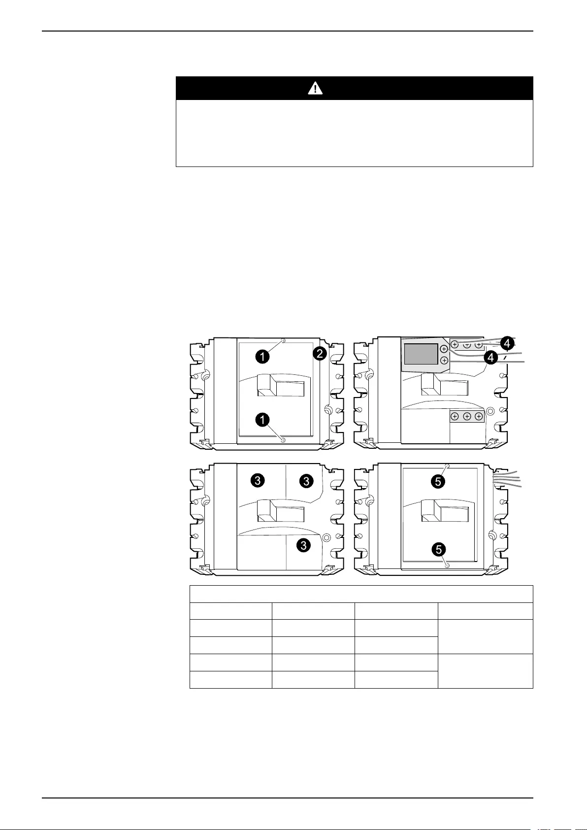
10–40 kVA 3:1 and 3:3 UPS Product Overview
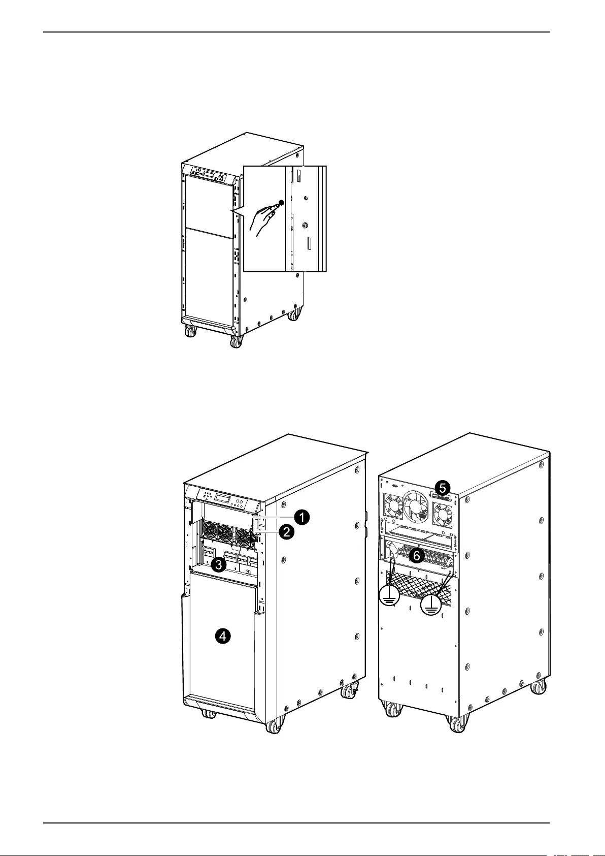
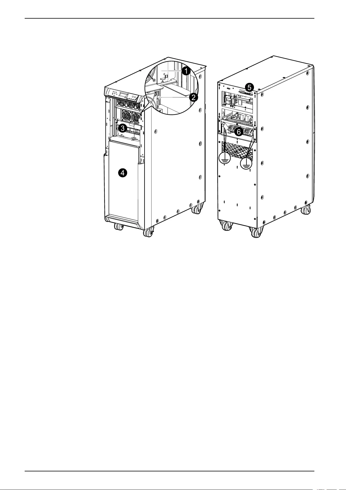
UPS Product Overview
The communication board, network management card, breakers, and battery
shelves are located behind the front door and accessed by pushing the white dot
on the right side of the door. The connectors and power terminals are accessed
from the rear.
Galaxy 300 30 kVA/ 40 kVA 3:3
Front View and Rear View
1. Communication board (only for Schneider Electric Service)
2. Network management card
3. Breakers
4. Battery shelves
18 990–3618G-001
UPS Product Overview 10–40 kVA 3:1 and 3:3
5. Dry contact terminal, EPO, external battery breaker signal, and external battery
temperature (ATIZ)
6. Power terminals
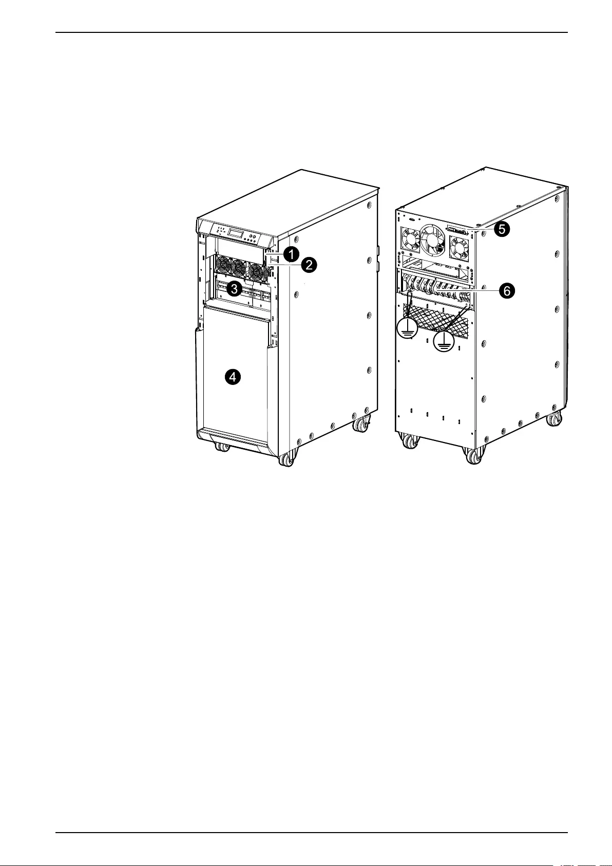
Galaxy 300 30 kVA 3:1
Front View and Rear View
1. Communication board (only for Schneider Electric Service)
2. Network management card
3. Breakers
4. Battery shelves
5. Dry contact terminal, EPO, external battery breaker signal, and external battery
temperature (ATIZ)
6. Power terminals
990–3618G-001 19
10–40 kVA 3:1 and 3:3 UPS Product Overview
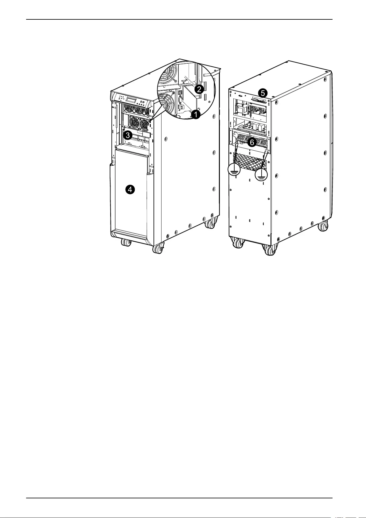
Galaxy 300 10 kVA/ 15 kVA/ 20 kVA 3:3
Front View and Rear View
1. Communication board (only for Schneider Electric Service)
2. Network management card
3. Breakers
4. Battery shelves
5. Dry contact terminal, EPO, external battery breaker signal, and external battery
temperature (ATIZ)
6. Power terminals
20 990–3618G-001
UPS Product Overview 10–40 kVA 3:1 and 3:3
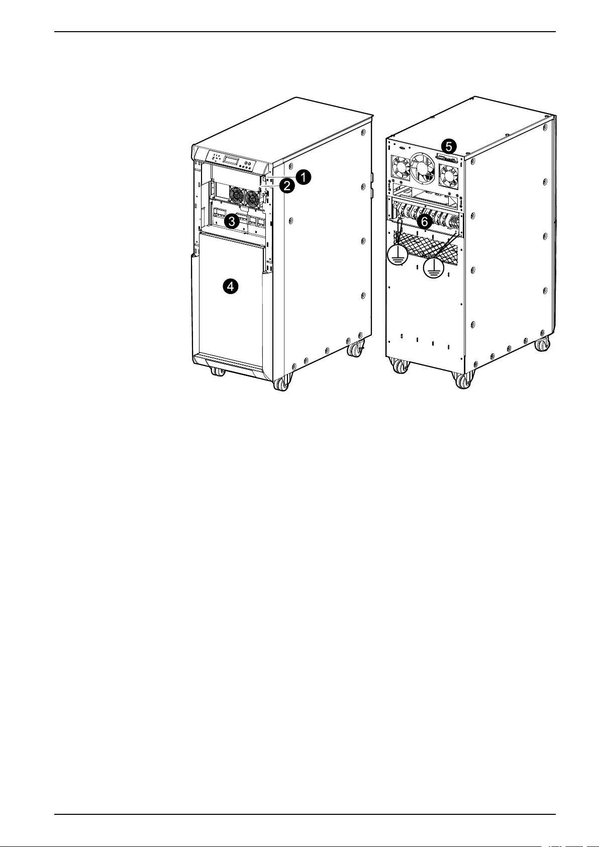
Galaxy 300 20 kVA 3:1
Front View and Rear View
1. Communication board (only for Schneider Electric Service)
2. Network management card
3. Breakers
4. Battery shelves
5. Dry contact terminal, EPO, external battery breaker signal, and external battery
temperature (ATIZ)
6. Power terminals
990–3618G-001 21
10–40 kVA 3:1 and 3:3 UPS Product Overview
Galaxy 300 10 kVA/ 15 kVA 3:1
Front View and Rear View
1. Communication board (only for Schneider Electric Service)
2. Network management card
3. Breakers
4. Battery shelves
5. Dry contact terminal, EPO, external battery breaker signal, and external battery
temperature (ATIZ)
6. Power terminals
Parallel System
The UPS can be installed in parallel with a maximum of two UPS units. Install both
UPS units separately as instructed in this manual. The parallel connection between
the two UPS units can only be carried out by a Schneider Electric Field Service
Engineer using the parallel kit bought separately.
22 990–3618G-001
UPS Product Overview 10–40 kVA 3:1 and 3:3
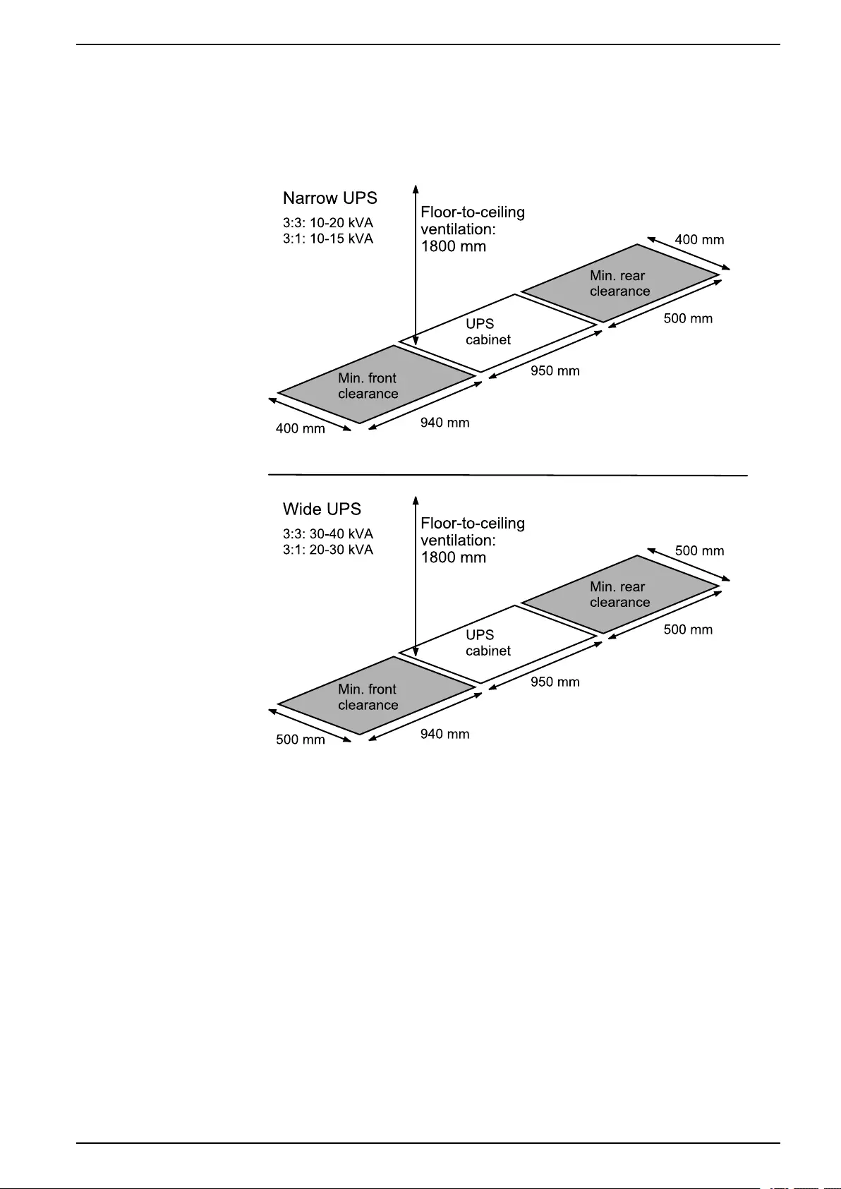
UPS Cabinet Clearance
NOTE: Clearance dimensions are published for airflow and service access only.
Consult with the local safety codes and standards for additional requirements in
your local area.
NOTE: 500 mm rear service clearance is recommended.
990–3618G-001 23
10–40 kVA 3:1 and 3:3 Prepare for Installation
Prepare for Installation
Floor Anchoring (Optional)
CAUTION
HAZARD OF TILTING
A UPS configuration without internal batteries must be anchored to the floor
because it is top-heavy.
Failure to follow these instructions can result in injury or equipment
damage.
NOTE: For parallel systems the distance between the UPS cabinets is limited. The
parallel kit includes two cables (5 and 15 meters). The maximum distance between
two UPS cabinets is 2 m for the 5 m cable and 12 m for the 15 m cable.
NOTE: The UPS system and battery cabinet must be installed on a non-
inflammable, level, and solid floor.
NOTE: The UPS can be anchored to the floor in two ways depending on the
available floor space.
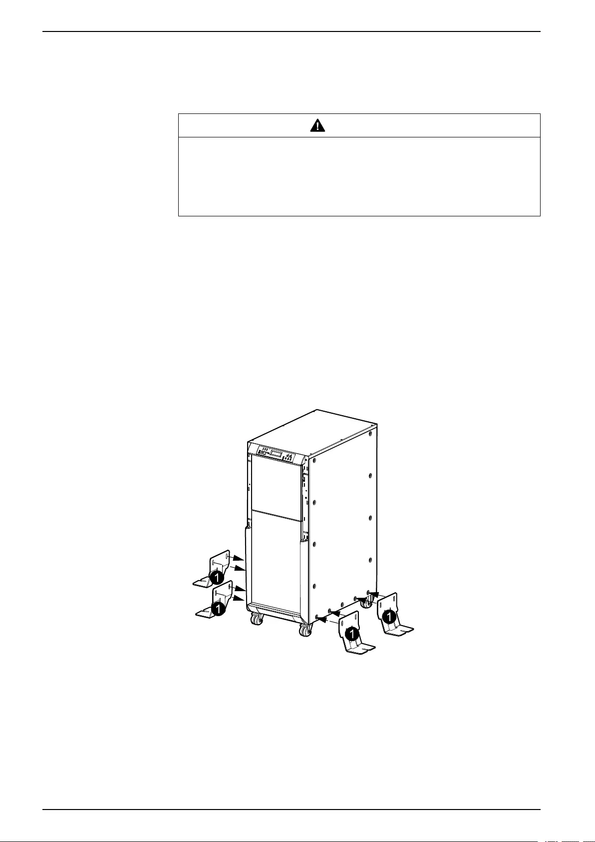
Method 1: Unlimited Space Available
1. Mount the four brackets on the UPS as shown.
Front View
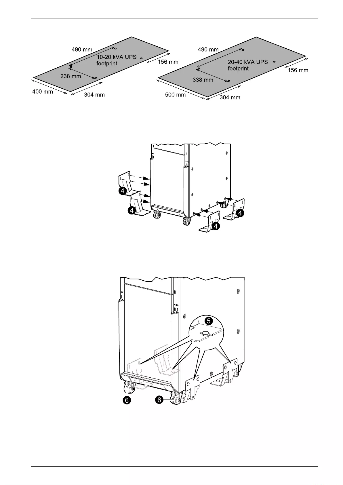
Method 2: Limited Space Available
1. Drill four holes according to the UPS footprint (see illustration) and install four
M8 bolts into the floor for anchoring.
24 990–3618G-001
Prepare for Installation 10–40 kVA 3:1 and 3:3
2. Tighten the bolts.
3. Push the UPS in between the four floor bolts.
4. Mount the four brackets on the UPS.
Front View
5. Make sure that the slots on each bracket grasp the floor bolts.
6. Lock the two front wheels by tightening the screws.
Front View
990–3618G-001 25
10–40 kVA 3:1 and 3:3 Prepare for Installation
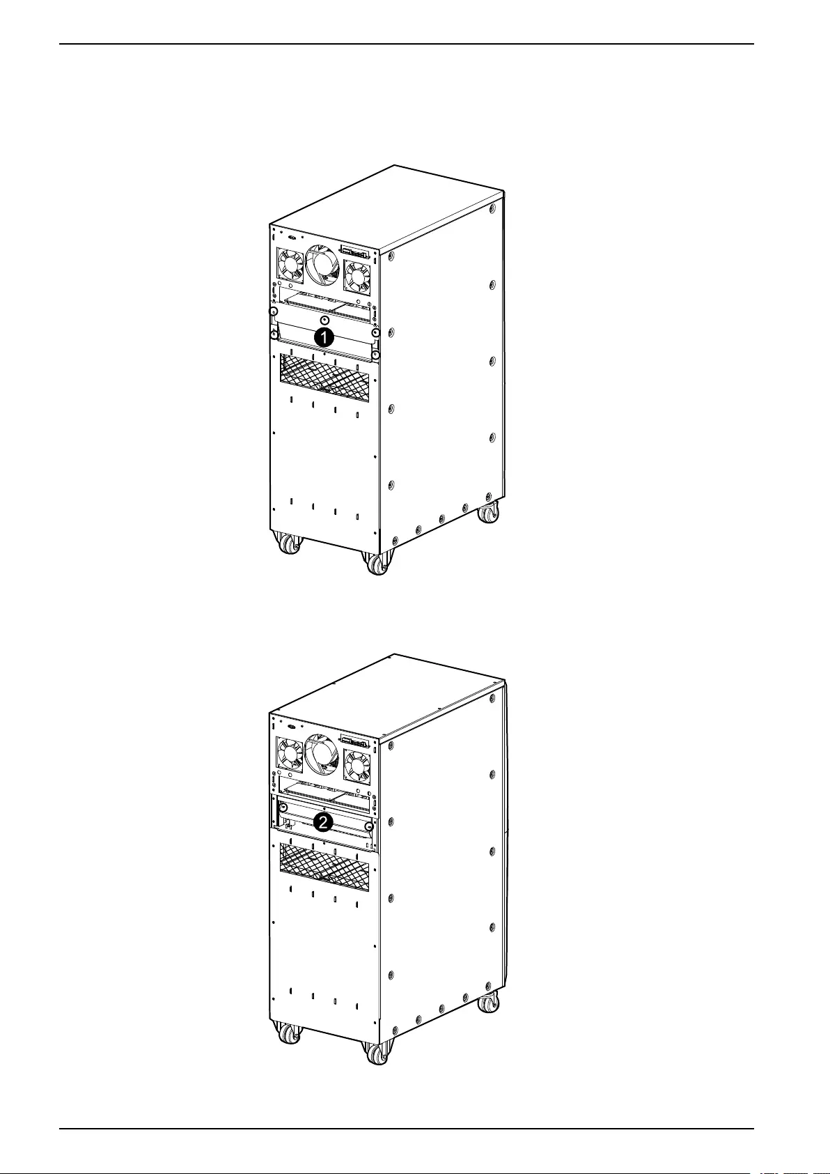
Prepare UPS for Cables
1. Loosen the five screws and remove the I/O sheet metal cover.
Rear View
2. Loosen the two screws and remove the plastic cover.
Rear View
26 990–3618G-001

Connect the Power Cables 10–40 kVA 3:1 and 3:3
Connect the Power Cables
NOTE: For installation of backfeed protection, see Install Backfeed Protection,
page 33.
Connect the UPS Power Cables
DANGER
HAZARD OF ELECTRIC SHOCK, EXPLOSION, OR ARC FLASH
In frequency converter operation mode the maintenance bypass breaker (Q3BP)
and the static bypass breaker (QM2) must be in the OFF (opened) position.
Failure to follow these instructions will result in death or serious injury.
NOTICE
RISK OF ERRATIC SYSTEM OPERATION
If the neutral line connection is not reliable, the system will work abnormally.
Failure to follow these instructions can result in equipment damage.
NOTE: A padlock is available from Schneider Electric and is advisable for the
frequency converter mode (padlock catalog number: 26970).
990–3618G-001 27
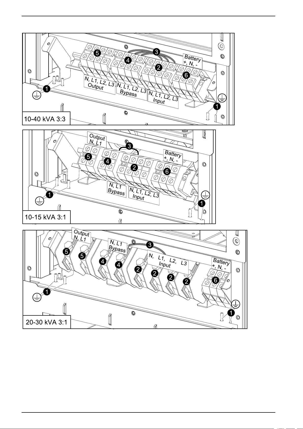
10–40 kVA 3:1 and 3:3 Connect the Power Cables
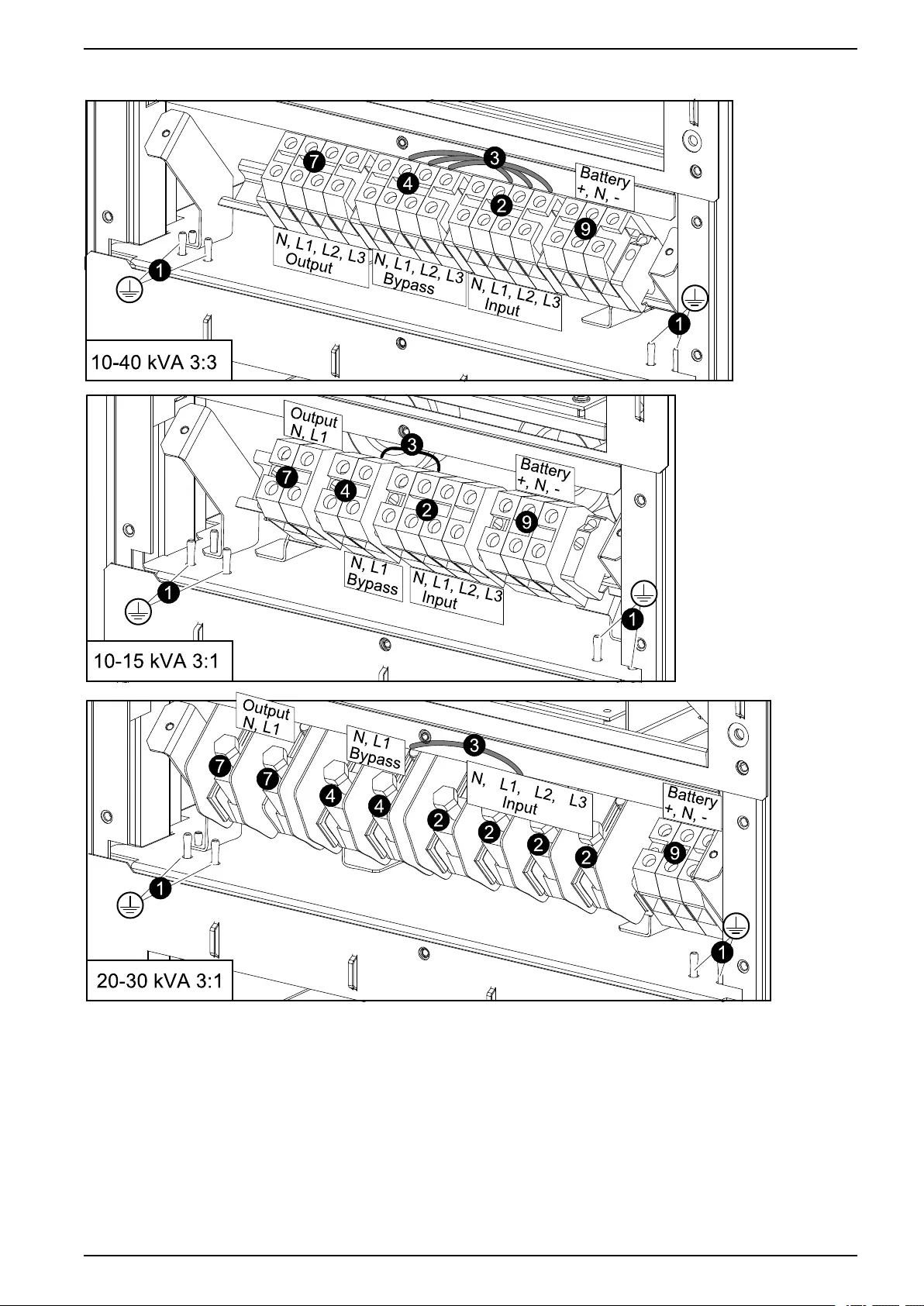
Rear View of the UPS
1. Connect the PE-cables for input, for bypass, and for the load.
2. Connect the input cables (N, L1, L2, L3) to the input terminals starting with N.
NOTE: For single mains systems, move to step 5.
3. Dual mains systems only: Remove the cable(s) between the bypass and the
input terminals.
28 990–3618G-001
Connect the Power Cables 10–40 kVA 3:1 and 3:3
4. Dual mains systems only: If you want the option of turning the UPS into
frequency converter operation (as described in the operation manual),
you must ignore this step and move to step 5. Otherwise, you must connect
the bypass cables to the bypass terminals. 3:3 (N, L1, L2, L3), 3:1 (N, L1).
5. Connect the cables from the critical load to the output terminals. 3:3 (N, L1, L2,
L3), 3:1 (N and L1).
6. External battery solution only: Connect the battery cables (BAT+, N, BAT-) to
the battery terminals. The battery cables will be connected to the external
battery solution later.
7. Reinstall the plastic cover and the I/O sheet metal cover removed in Prepare
UPS for Cables, page 26.
DANGER
HAZARD OF ELECTRIC SHOCK, EXPLOSION, OR ARC FLASH
The I/O sheet metal cover must be fixed in the lowest position for safety
reasons.
Failure to follow these instructions will result in death or serious injury.
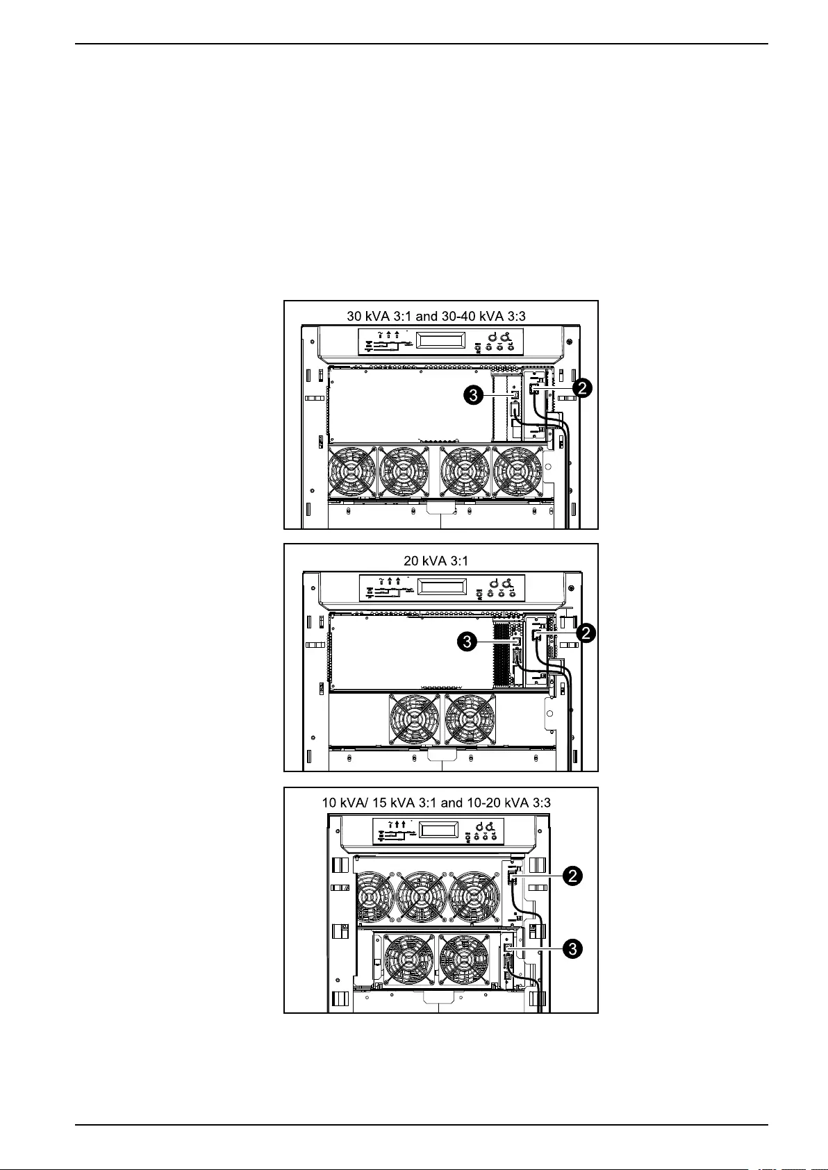
8. Bundle the input cables, the bypass cables, the battery cables (if present) and
the output cables as four separate groups of cables.
9. Attach all cables to the fixtures (shown below) with cable ties.
990–3618G-001 29
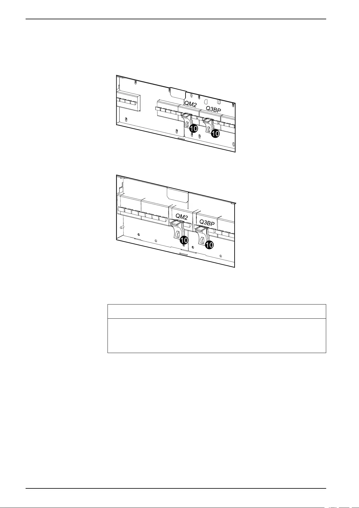
10–40 kVA 3:1 and 3:3 Connect the Power Cables
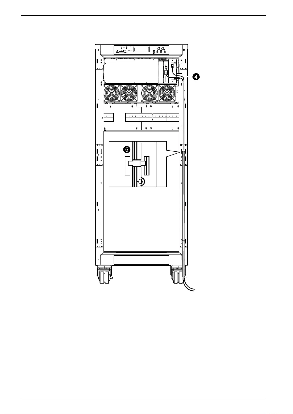
10.If the frequency converter option was made available by ignoring step 4, a
padlock from Schneider Electric must now be installed on the static bypass
breaker (QM2) and the maintenance bypass breaker (Q3BP) in the OFF
(opened) position.
Front View of 3:3 30–40 kVA, and 3:1 20–30 kVA
Front View of 3:3 10–20 kVA, and 3:1 10–15 kVA
Connect the UPS Power Cables for Standby Redundancy System
NOTICE
RISK OF ERRATIC SYSTEM OPERATION
If the neutral line connection is not reliable, the system will work abnormally.
Failure to follow these instructions can result in equipment damage.
NOTE: Only two UPS units can be installed in a standby redundancy system. Both
units must have the same power rating and topology (both 3:3 or both 3:1).
30 990–3618G-001
Connect the Power Cables 10–40 kVA 3:1 and 3:3
Rear View of the UPS
1. Connect the PE cables for input, for bypass, and for the load.
2. Connect the input cables (N, L1, L2, L3) to the input terminals starting with N on
UPS 1.
3. For Dual mains systems only: Remove the cable(s) between the input and
the bypass terminals on UPS 1.
4. For Dual mains systems only:Connect the bypass cables to the bypass
terminals (3:3 (N, L1, L2, L3), 3:1 (N, L1)) on UPS 1.
5. Connect input cables on UPS 2.
990–3618G-001 31
10–40 kVA 3:1 and 3:3 Connect the Power Cables
6. Remove the cable(s) between input and bypass terminals on UPS 2.
7. Connect output (3:3 (N, L1, L2, L3), 3:1 (N and L1)) from UPS 1 to the bypass
on UPS 2.
8. Connect the cables from the critical load to the output terminals (3:3 (N, L1, L2,
L3), 3:1 (N and L1)) on UPS 2.
9. External battery solution only: Connect the battery cables (BAT+, N, BAT-) to
the battery terminals. The battery cables will be connected to the external
battery solution later.
10.Reinstall the plastic cover and the I/O sheet metal cover removed while
preparing the UPS for cables.
DANGER
HAZARD OF ELECTRIC SHOCK, EXPLOSION, OR ARC FLASH
The I/O sheet metal cover must be fixed in the lowest position for safety
reasons.
Failure to follow these instructions will result in death or serious injury.
11.Bundle the input cables, the bypass cables, the battery cables (if present), and
the output cables as four separate groups of cables.
12.Attach all cables to the fixtures (shown below) with cable ties.
32 990–3618G-001

Install Backfeed Protection 10–40 kVA 3:1 and 3:3
Install Backfeed Protection
NOTE: The presence of a backfeed on each input mains (Input and Bypass input),
is mandatory according to IEC 62040-1.
An additional external isolation device must be installed in the UPS system. A
magnetic contactor or a circuit breaker with UVR (Under Voltage Release)
functionality can be used for this purpose. In the shown examples, the isolation
device is a magnetic contactor (marked with a C1 for single feed configurations
and marked with a C1 and C2 for dual feed configurations).
The isolation device must be able to carry the UPS input current, check with the
relevant input current of the UPS specifications.
NOTE: The 24 V source should be generated from the input source in single mains
configurations and from the bypass source in dual mains configurations.
NOTE: The examples shown in the backfeed protection instructions are for TN
earthing systems. For other earthing systems, the external isolation device
schematics are similar; refer to Galaxy 300 Earthing Manual. In case of an IT
earthing system installation, where the upstream protection is a 4 pole device, the
external isolation device must also be 4 pole.
If the UPS is fed by single mains, connect the backfeed protection as instructed in
Install External Backfeed Protection in System with Single Mains, page 33.
If the UPS is fed by dual mains only, connect the backfeed protection as instructed
in Install External Backfeed Protection in System with Dual Mains, page 34.
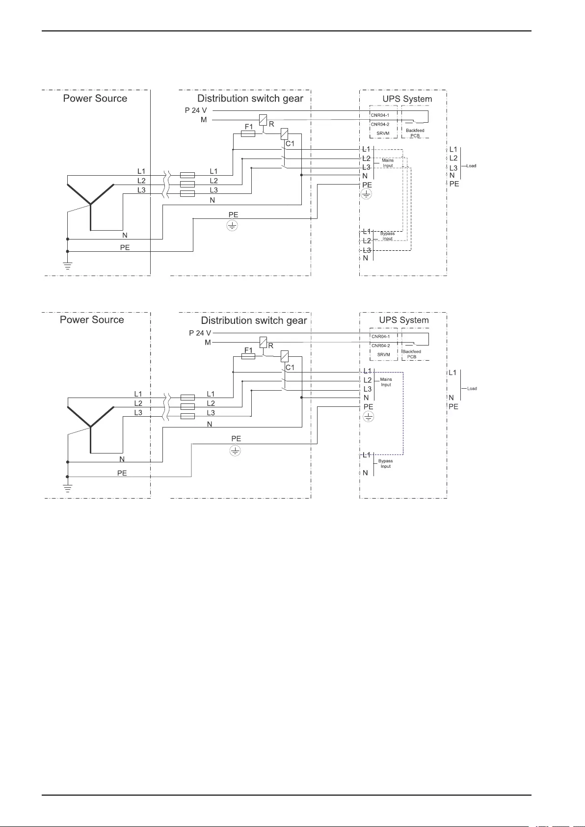
Install External Backfeed Protection in System with Single Mains
1. Connect UPS backfeed dry contact CNR04-1 with an external +24 VDC supply
pole “+” (the UPS backfeed dry contact CNR04-1 CNR04-2 is connected later
with the other signal cables).
2. Connect UPS backfeed dry contact CNR04-2 with a terminal of the relay R coil.
3. Connect the other terminal of the relay R coil with +24 VDC supply pole “-”(M).
4. Serial-connect the fuse (F1), the auxiliary contact of relay R and the coil of C1
as shown in the illustration below.
5. Connect C1 (L1, L2, L3) to UPS input (L1, L2, L3) as shown in the illustration
below.
6. Connect C1 (L1, L2, L3) to input feeding (L1, L2, L3) in distribution switchgear
as shown in the illustration below.
990–3618G-001 33
10–40 kVA 3:1 and 3:3 Install Backfeed Protection
7. Connect UPS input (N), PE to input feeding (N), PE in distribution switchgear.
Illustration 1 for Single Mains 3:3 UPS and External Isolation Device
Illustration 2 for Single Mains 3:1 UPS and External Isolation Device
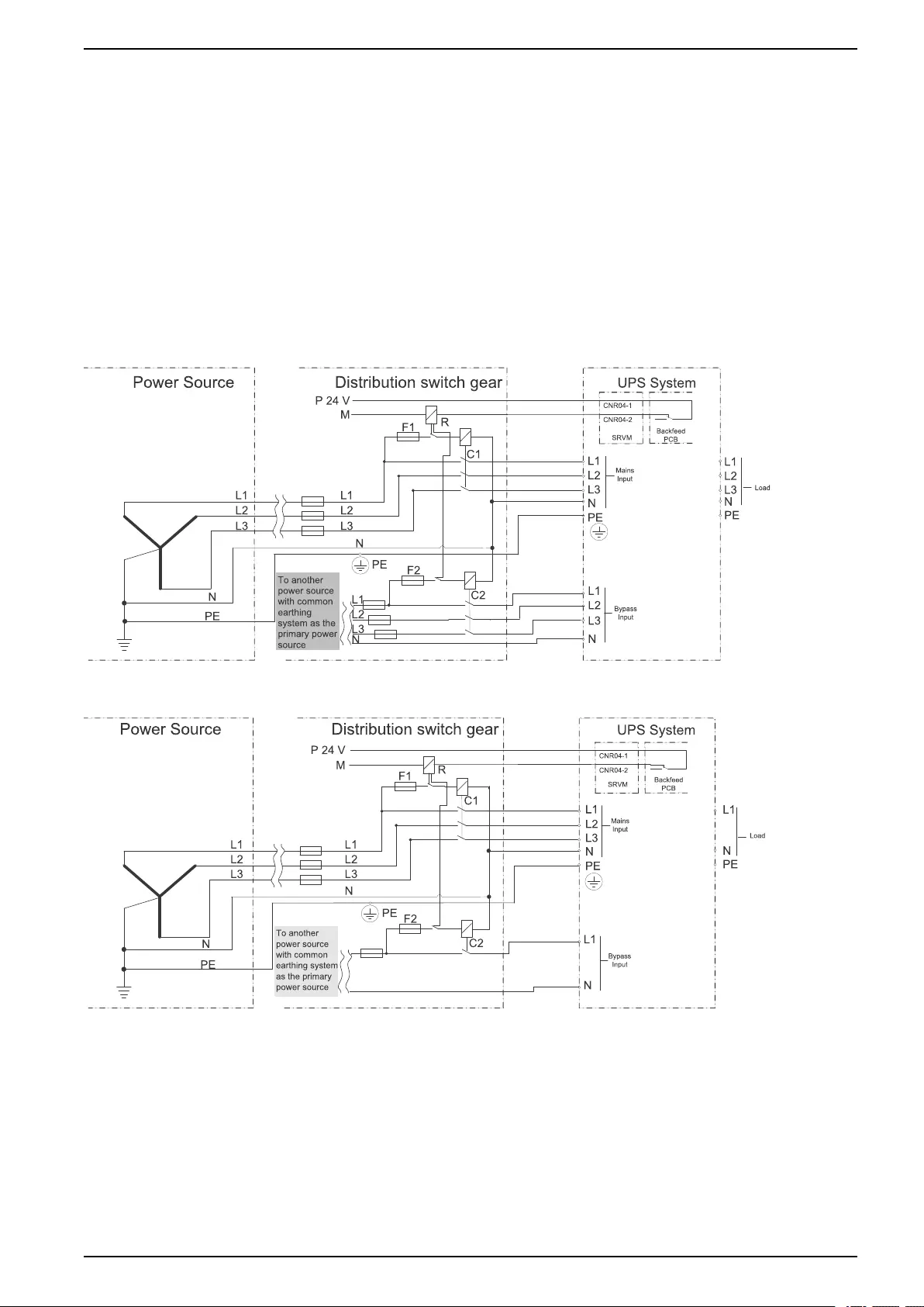
Install External Backfeed Protection in System with Dual Mains
1. Remove the internal cable connection between bypass and input terminals on
the UPS.
2. Connect UPS backfeed dry contact CNR04-1 with an external +24 VDC supply
pole “+” (the UPS backfeed dry contact CNR04-1 CNR04-2 is connected later
with the other signal cables).
3. Connect UPS backfeed dry contact CNR04-2 with a terminal of the relay R coil.
4. Connect the other terminal of the relay R coil with +24 VDC supply pole “-”(M).
5. Serial-connect the fuse (F1), the auxiliary contact of relay R and the coil of C1
as shown in the illustration below.
6. Connect C1 (L1, L2, L3) to UPS input (L1, L2, L3) as the shown in the
illustration below.
7. Connect C1 (L1, L2, L3) to input feeding (L1, L2, L3) in customer’s distribution
switchgear as shown in the illustration below.
8. Connect UPS input (N), PE to input feeding (N), PE in customer’s distribution
switchgear.
9. Connect the other fuse (F2), the other auxiliary contact of relay R and the coil of
C2 as shown in the illustration below.
34 990–3618G-001
Install Backfeed Protection 10–40 kVA 3:1 and 3:3
10.
a. For 3:3: Connect C2 (L1, L2 , L3) with UPS bypass input (L1, L2 , L3) as the
illustration 3 below.
b. For 3:1: Connect C2 (only L1) with UPS bypass input (only L1) as shown in
illustration 4 below.
11.
a. For 3:3: Connect C1 (L1, L2, L3) with the input feeding (L1, L2, L3) in
distribution switchgear as shown in illustration 3 below.
b. For 3:1: Connect C1 (L1, L2, L3) with the input feeding (L1, L2, L3) in
distribution switchgear as shown in illustration 4 below.
12.Connect bypass input (N) with mains feeding (N) in distribution switchgear.
Illustration 3 for Dual Mains 3:3 UPS and External Isolation Device
Illustration 4 for Dual Mains 3:1 UPS and External Isolation Device
990–3618G-001 35

10–40 kVA 3:1 and 3:3 Install Battery Solution
Install Battery Solution
DANGER
HAZARD OF ELECTRIC SHOCK, EXPLOSION, OR ARC FLASH
The Galaxy 300 UPS can be used with EITHER internal or external batteries. A
UPS unit containing internal batteries CANNOT be used with external batteries.
Remove internal batteries before connecting external batteries to the UPS.
Failure to follow these instructions will result in death or serious injury.
DANGER
HAZARD OF ELECTRIC SHOCK, EXPLOSION, OR ARC FLASH
• Make sure that the battery breaker is open before starting.
• Check the DC voltages with a DC voltage multimeter versus the battery
voltage before continuing.
Failure to follow these instructions will result in death or serious injury.
Depending on your chosen solution, follow the appropriate steps in this chapter.
Solutions described:
•Internal batteries for the UPS – See Install the Internal Batteries in the Galaxy
300 UPS, page 40.
•Galaxy 300 battery cabinet (1300 mm) – See Install a Galaxy 300 Battery
Cabinet (1300 mm), page 44.
•1900 mm battery cabinet – See Install a Galaxy 1900 mm Battery Cabinet,
page 53.
•Third party battery solution – See Connect Battery and Signal Cables to
Third Party Battery Solution, page 60.
36 990–3618G-001
Install Battery Solution 10–40 kVA 3:1 and 3:3
Battery Cabinet Product Overview
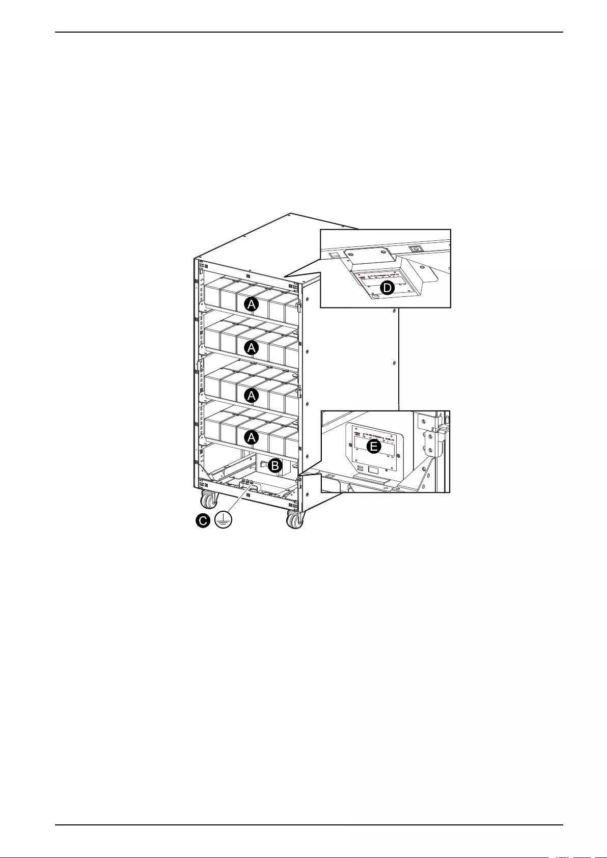
Galaxy 300 Battery Cabinet (1300 mm)
A. Battery shelves
B. Battery circuit breaker
C. Ground cable connection (from the UPS)
D. Battery temperature sensor (ATIZ)
E. Connection terminal (for ATIZ, circuit breaker detection and power supply)
Front View
990–3618G-001 37
10–40 kVA 3:1 and 3:3 Install Battery Solution
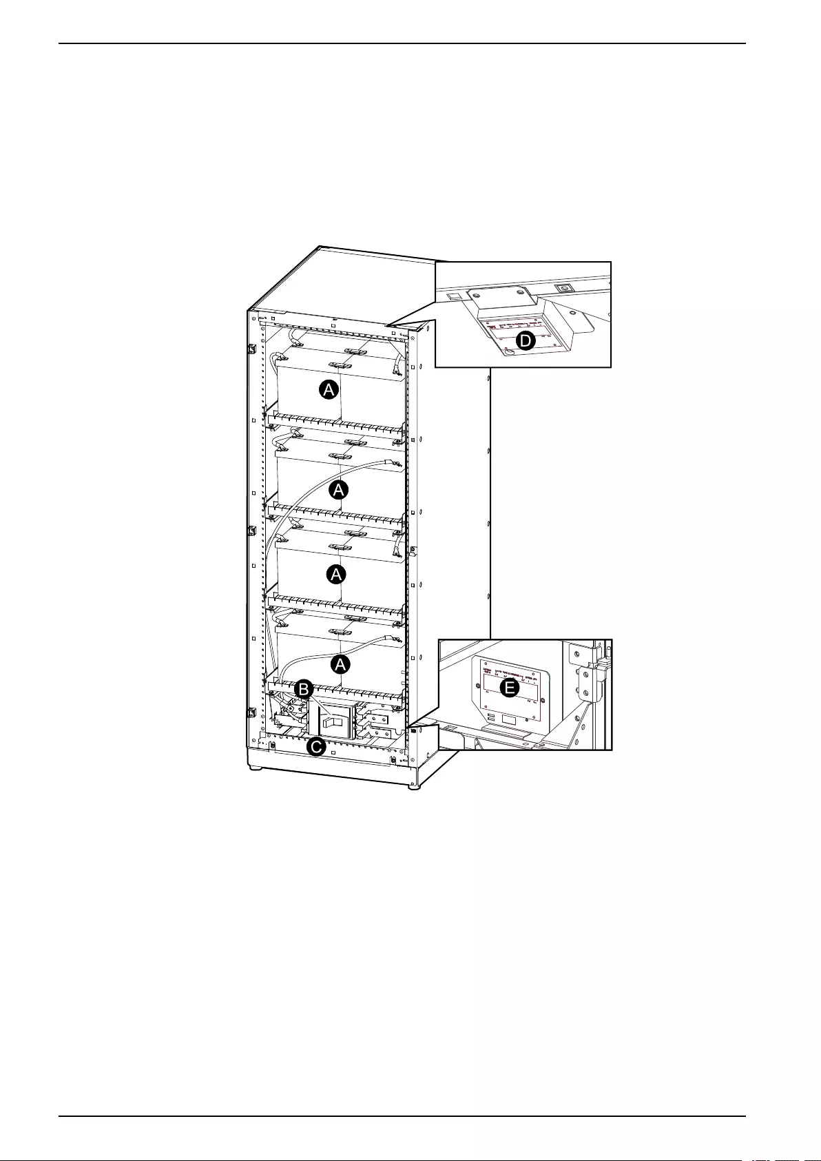
Galaxy 1900 mm Battery Cabinet
A. Battery shelves
B. Battery circuit breaker
C. Ground cable connection (from the UPS)
D. Battery temperature sensor (ATIZ board)
E. Cable terminal board (for ATIZ, circuit breaker detection and power supply)
Front View
38 990–3618G-001
Install Battery Solution 10–40 kVA 3:1 and 3:3
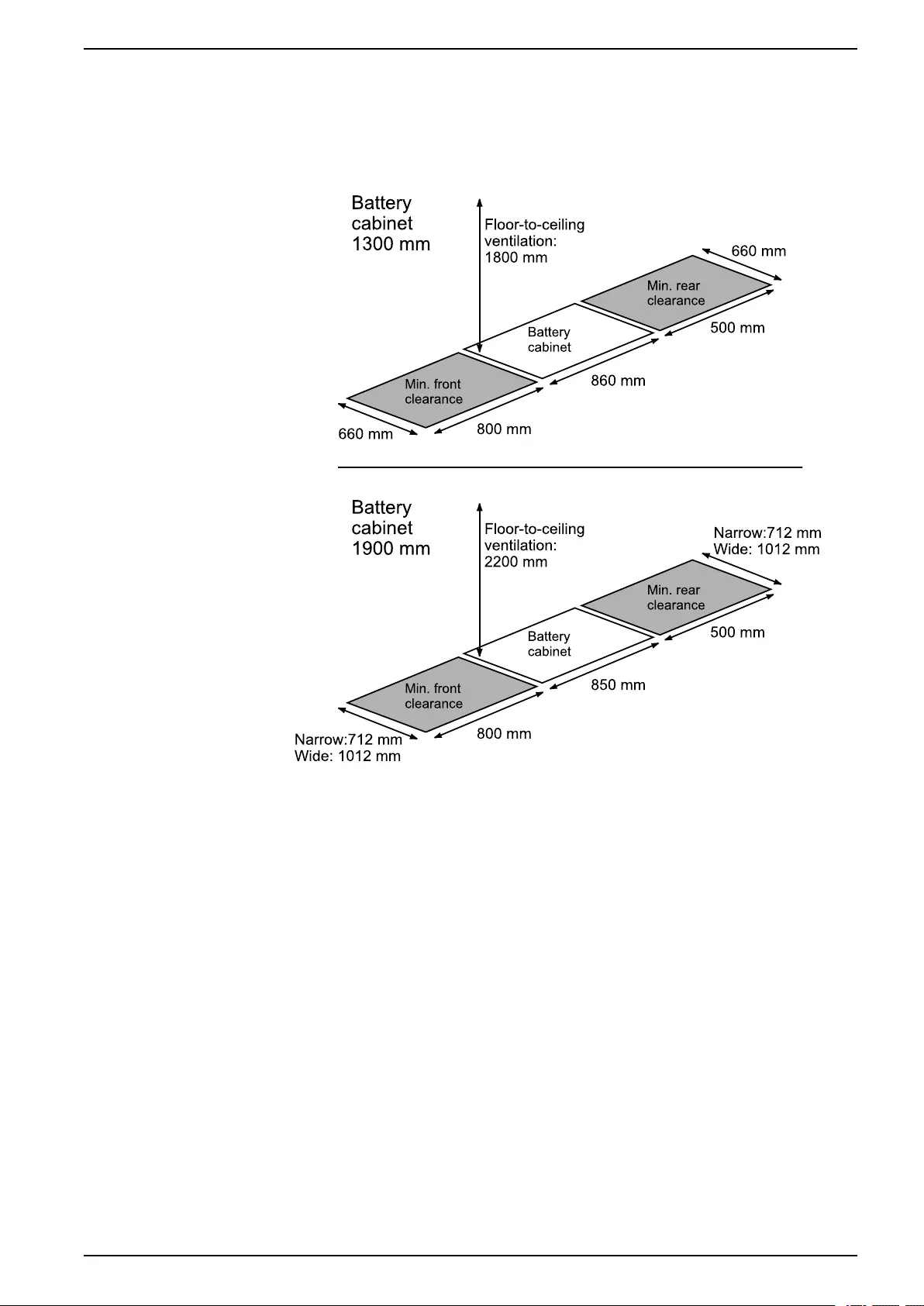
Battery Cabinet Clearance
NOTE: Clearance dimensions are published for airflow and service access only.
Consult with the local safety codes and standards for additional requirements in
your local area.
NOTE: 500 mm rear service clearance is recommended.
990–3618G-001 39
10–40 kVA 3:1 and 3:3 Install Battery Solution
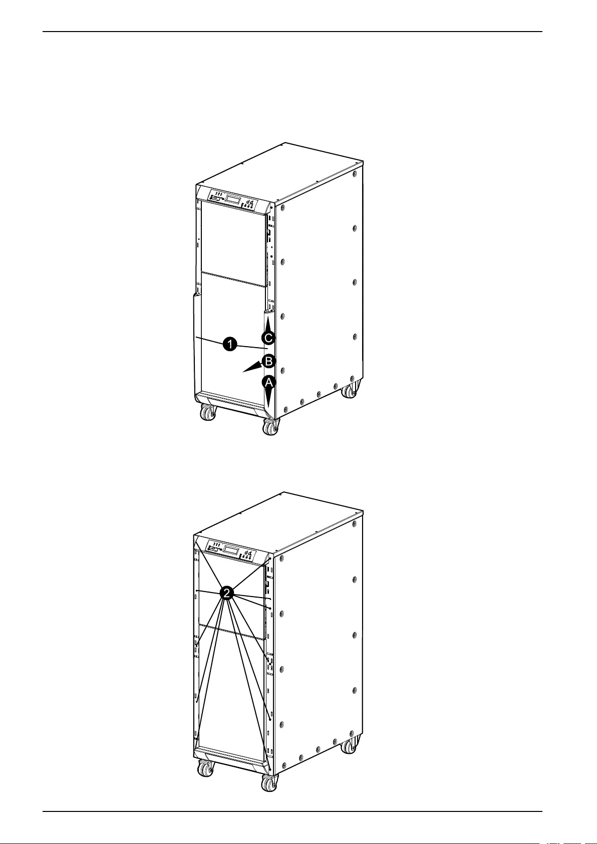
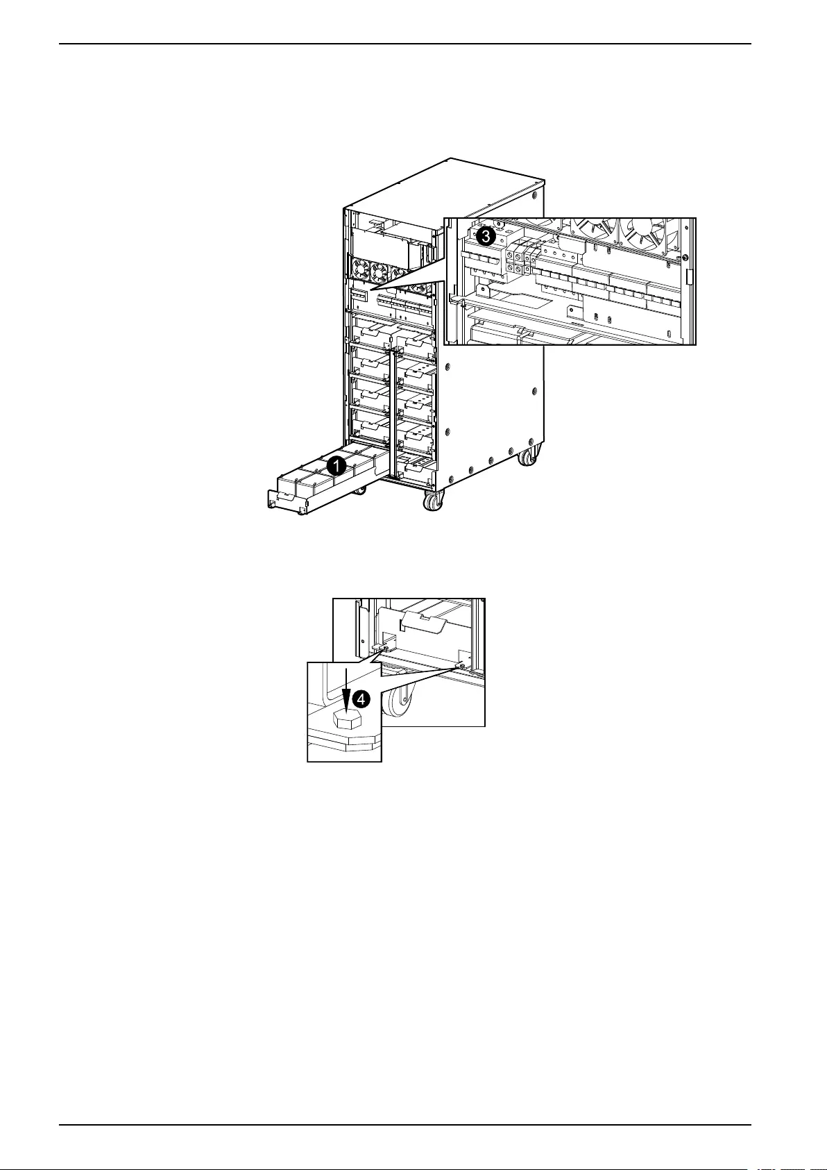
Install the Internal Batteries in the Galaxy 300 UPS
1. Remove the two bottom side covers with two hands by pushing the covers
down approx. 3 mm (A), tilting them outwards in a 10° angle (B) and lifting them
upwards (C).
Front View
2. Loosen the screws on the front cover plate.
Front View
40 990–3618G-001
Install Battery Solution 10–40 kVA 3:1 and 3:3
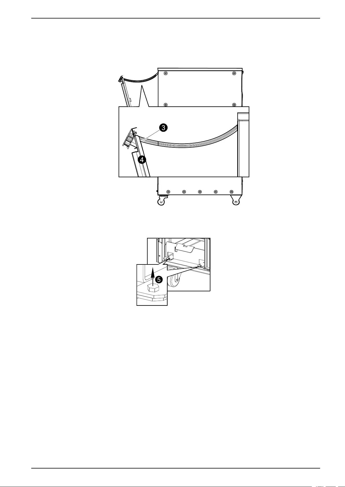
3. Tilt out the front cover and disconnect the flat cable between the display and the
UPS cabinet.
4. Remove the front cover.
Side View
5. Remove the bolt on each side of all shelves where necessary.
Front View
Cable Connection of Pre-Installed Internal Batteries
1. Remove all strapping and cardboard from the batteries.
2. Interconnect the shelves according to the labels in the cabinet or the diagrams
inside the battery cabinet (cables are provided).
990–3618G-001 41
10–40 kVA 3:1 and 3:3 Install Battery Solution
3. Remove the plate and connect the battery cable from the shelves to the battery
breaker according to the labels in the cabinet or the diagrams inside the battery
cabinet (cables are provided).
Front View
4. Reattach the bolt on each side of all shelves where necessary.
Front View
5. Lift up the front cover and reconnect the flat cable between the display and the
UPS.
6. Reinstall the front cover with the screws.
Cable Connection of Not Pre-Installed Internal Batteries
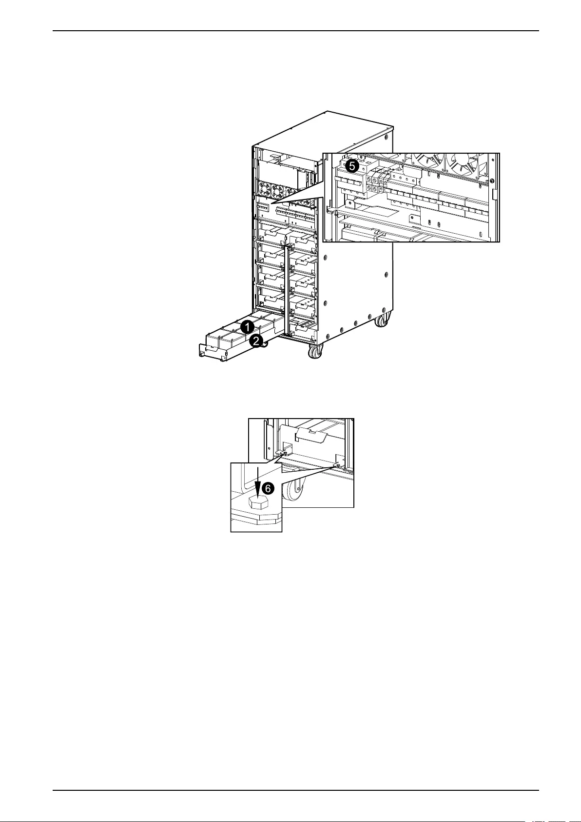
1. Pull out the required number of shelves needed for the batteries.
2. Place the batteries on the shelves and interconnect the batteries (cables are
not provided). Secure the cables with cable ties.
3. Push the battery shelves into the cabinet.
4. Interconnect the shelves according to the diagrams inside the battery cabinet
(cables are not provided).
42 990–3618G-001
Install Battery Solution 10–40 kVA 3:1 and 3:3
5. Remove the plate and connect the battery cable from the shelves to the battery
breaker according to the diagrams inside the battery cabinet (cables are not
provided).
Front View
6. Reattach the bolt on each side of all shelves where necessary.
Front View
7. Lift up the front cover and reconnect the flat cable between the display and the
UPS.
8. Reinstall the front cover with the screws.
990–3618G-001 43
10–40 kVA 3:1 and 3:3 Install Battery Solution
Install a Galaxy 300 Battery Cabinet (1300 mm)
Prepare Galaxy 300 Battery Cabinet (1300 mm) for Cables
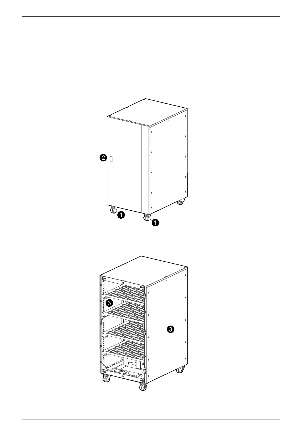
1. Lock the two front wheels by tightening the screws.
2. Open the unlocked front door.
NOTE: The key to the door can be found in the accessories package located in
the cabinet.
Front View
3. Remove both side panels.
Front View
44 990–3618G-001
Install Battery Solution 10–40 kVA 3:1 and 3:3
Connect Internal Cables in Galaxy 300 Battery Cabinet (1300
mm) with Pre-Installed Batteries
DANGER
HAZARD OF ELECTRIC SHOCK, EXPLOSION, OR ARC FLASH
Remove all cardboard pieces, which are used to protect the batteries during
transport. Make sure that cables and copper busbars are separated.
Failure to follow these instructions will result in death or serious injury.
NOTE: A maximum of two battery cabinets can be connected to the UPS (one
battery cabinet with a circuit breaker plus one cabinet without a circuit breaker) by
a batch cable between the UPS and the circuit breaker in the battery cabinet.
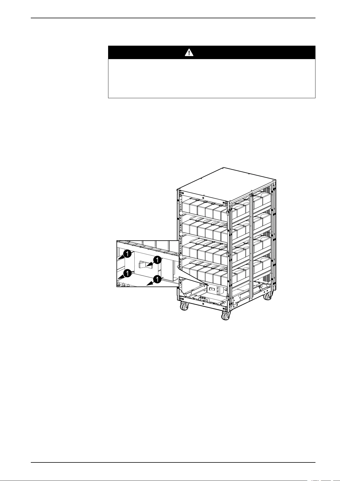
1. Remove the left and right plastic cover from the battery breaker by removing the
four screws (two on each plastic cover).
Front View
2. Cut off the belts to remove the carton paper.
3. Run the cables inside each shelf and connect to the batteries.
4. Run the cables between the shelves.
990–3618G-001 45
10–40 kVA 3:1 and 3:3 Install Battery Solution
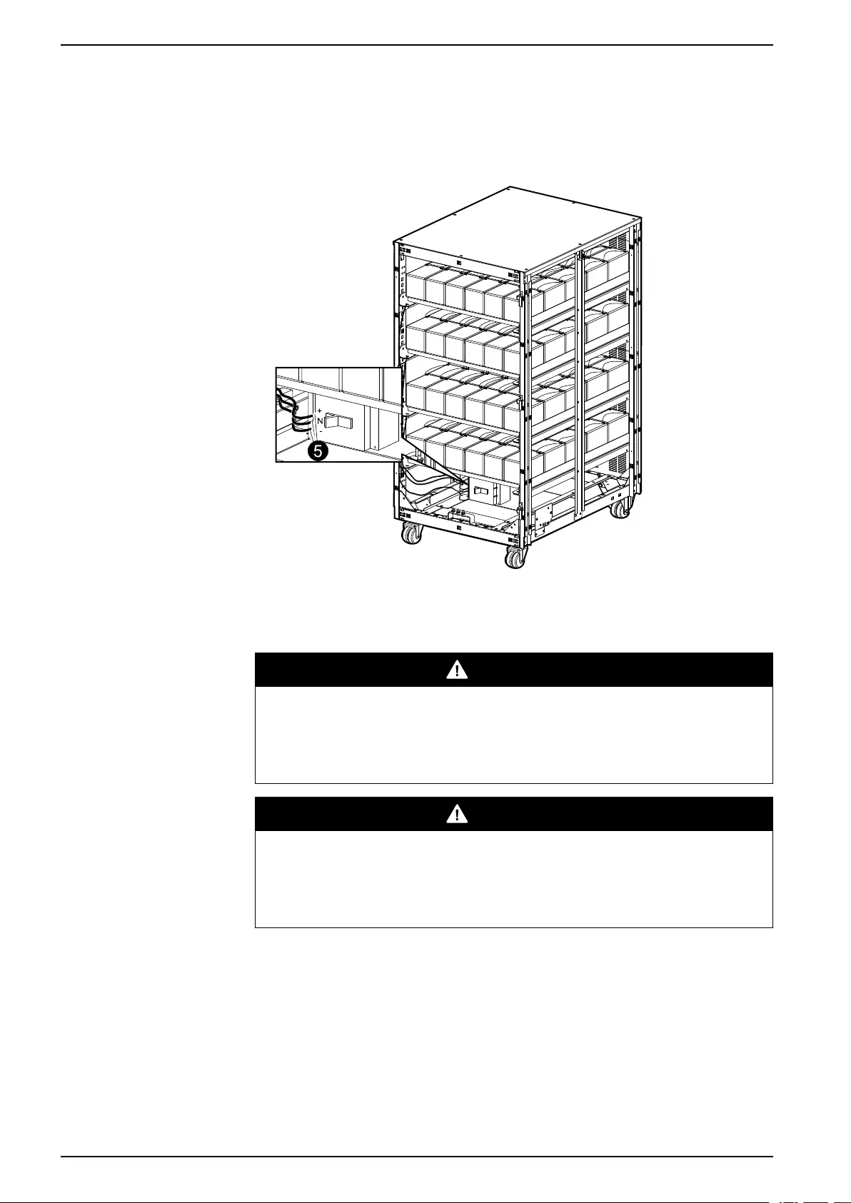
5. Run the cables between the shelves and the circuit breaker.
NOTE: If the cables have more than one terminal, then the unconnected
terminals must be isolated with insulation tape before connecting the other
terminal.
Front View
Connect Internal Cables in Galaxy 300 Battery Cabinet (1300
mm) without Pre-Installed Batteries
DANGER
HAZARD OF ELECTRIC SHOCK, EXPLOSION, OR ARC FLASH
Schneider Electric is not responsible for the wiring of external third party
batteries. Follow the instructions from the battery manufacturer.
Failure to follow these instructions will result in death or serious injury.
DANGER
HAZARD OF ELECTRIC SHOCK, EXPLOSION, OR ARC FLASH
Remove all cardboard pieces, which are used to protect the batteries during
transport. Make sure that cables and copper busbars are separated.
Failure to follow these instructions will result in death or serious injury.
NOTE: Before the installation of batteries, you must select and follow the diagrams
inside the battery cabinet which apply to your configuration.
NOTE: The maximum load capacity of each battery shelf is 155 kg.
NOTE: A maximum of four battery shelves can be installed.
NOTE: A maximum of two battery cabinets can be connected to the UPS (one
battery cabinet with a circuit breaker plus one cabinet without a circuit breaker) by
a batch cable between the UPS and the circuit breaker in the battery cabinet.
1. Insert the batteries on the shelves starting from the bottom according to the
relevant diagram inside the battery cabinet.
46 990–3618G-001
Install Battery Solution 10–40 kVA 3:1 and 3:3
2. Install a battery breaker.
3. Cut off the belts to remove the carton paper.
4. Run the cables inside each shelf and connect to the batteries.
5. Run the cables between the shelves.
6. Run the cables between the shelves and the circuit breaker.
NOTE: If the cables have more than one terminal, then the unconnected
terminals must be isolated with insulation tape before connecting the other
terminal.
Front View
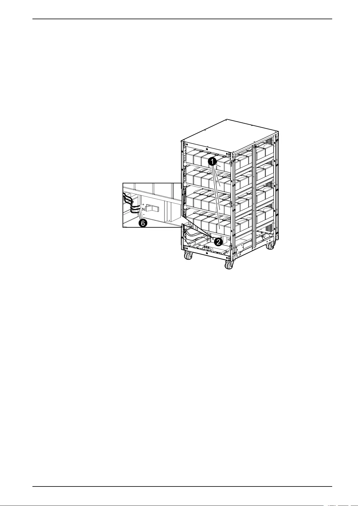
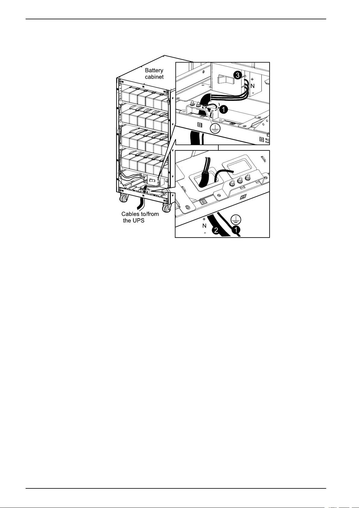
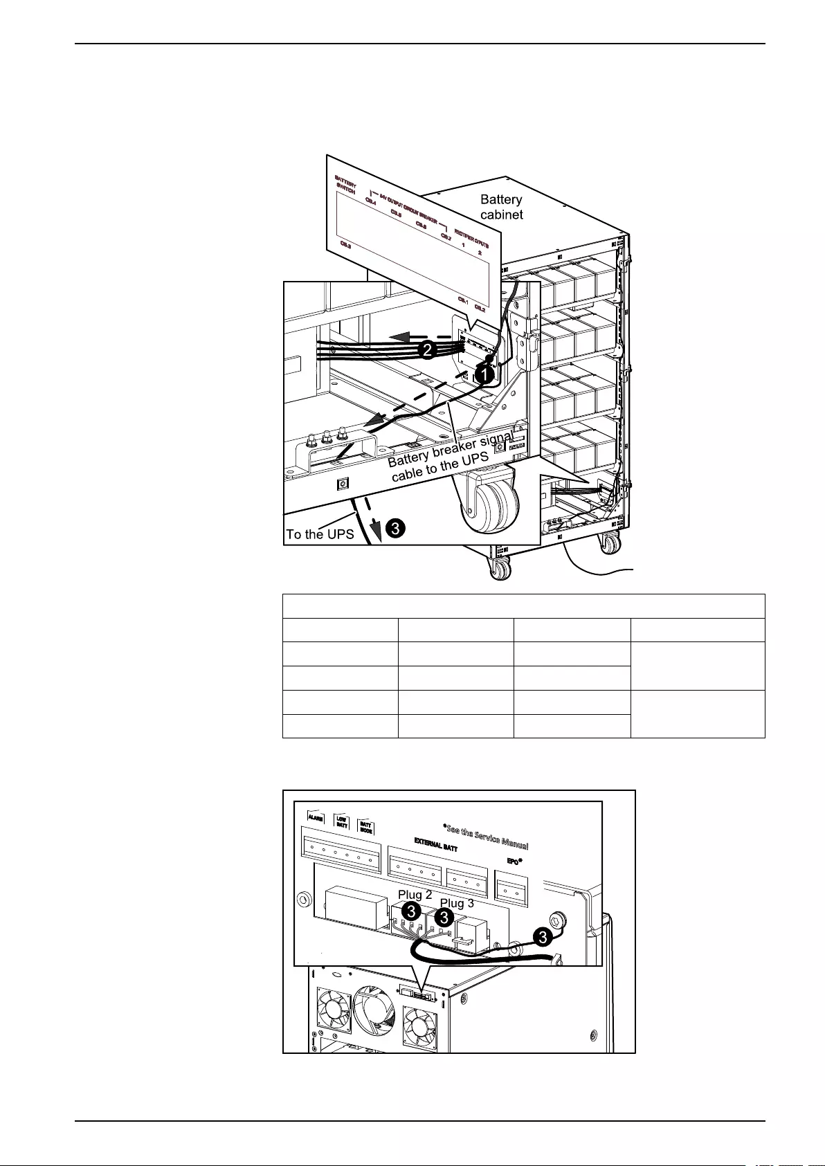
Connect Battery Cables from UPS to the Galaxy 300 Battery Cabinet (1300 mm)
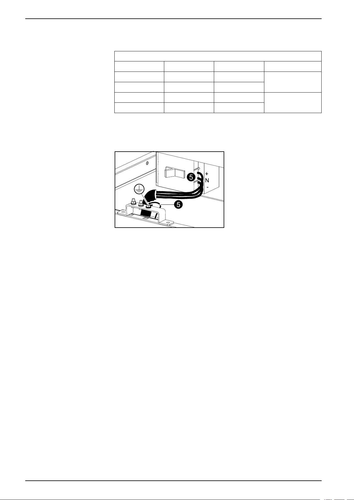
1. Run the Protective Earth (PE) cable from the UPS up through the bottom front
hole of the battery cabinet and connect it to the busbar.
2. Run the battery cables (BAT+, N, and BAT-) from the UPS up through the
bottom front hole.
3. Attach the cables to the right side of the battery breaker.
990–3618G-001 47
10–40 kVA 3:1 and 3:3 Install Battery Solution
4. Reinstall the side panels.
Front View
Connect External Battery Temperature (ATIZ) and External Battery Breaker Signal
between the UPS and the Galaxy 300 Battery Cabinet (1300 mm)
NOTE: The ATIZ cable is for the external battery temperature detection signal
(cable is pre-installed).
NOTE: The battery cable is for the external battery breaker signal (cable is pre-
installed).
NOTE: The connection of signal cables is only applicable between the UPS and
battery cabinet 1.
1. Run the combined battery breaker and ATIZ signal cable from the connection
terminal on the battery cabinet to the UPS.
2. Run the four cables from the connection terminal to the battery breaker on the
battery cabinet (see the below table for cable description).
48 990–3618G-001
Install Battery Solution 10–40 kVA 3:1 and 3:3
3. Connect the combined battery breaker and ATIZ signal cable to the UPS as
shown and make sure to connect the cable with shielded layer to the screw on
the UPS.
Front View of Battery Cabinet (1300 mm)
Cable description
Cable color Cable label Description
Yellow QB OF-11 CB contact signal – to the auxiliary contact
(normally closed)
White QB OF-14 CB contact signal
Red QB OF-D4 +12 V power supply – to the coil terminal
Black QB OF-D1 -12 V power supply
Rear View of the UPS
NOTE: The cable(s) is routed the same way as the EPO cable.
990–3618G-001 49

10–40 kVA 3:1 and 3:3 Install Battery Solution
Connect Battery and Signal Cables from the Galaxy 300 Battery Cabinet (1300 mm) to a
Running UPS
DANGER
HAZARD OF ELECTRIC SHOCK, EXPLOSION, OR ARC FLASH
This procedure describes how to connect a battery cabinet to a UPS running in
normal operation. Do not connect a battery cabinet to a running UPS with
internal batteries – Remove all internal batteries first.
Failure to follow these instructions will result in death or serious injury.
NOTE: A maximum of two battery cabinets can be connected to the UPS (one
battery cabinet with a circuit breaker plus one cabinet without a circuit breaker) by
a batch cable between the UPS and the circuit breaker in the battery cabinet.
NOTE: Before carrying out the below procedure, make sure that the UPS is
running in normal operation with no internal UPS faults displayed. In normal
operation four breakers (QM1,QFB,QM2,QOP) must be in the ON (closed)
position and two breakers (Q3BP,QB) must be in the OFF (opened) position.
1. Turn the UPS into maintenance bypass operation:
a. Press the Inverter OFF button for three seconds and then turn the input
breaker (QM1) to the OFF (opened) position.
b. Turn the maintenance bypass breaker (Q3BP) to the ON (closed) position.
c. Turn the static bypass breaker (QM2) to the OFF (opened) position.
d. Turn the output breaker (QOP) to the OFF (opened) position.
2. Isolate the batteries by turning the UPS battery cabinet breaker (QFB) to the
OFF (opened) position.
DANGER
HAZARD OF ELECTRIC SHOCK, EXPLOSION, OR ARC FLASH
Check the DC voltages with a DC voltage multimeter versus the battery
voltage before continuing.
Failure to follow these instructions will result in death or serious injury.
3. Run a Protective Earth (PE) cable from the UPS up through the bottom front
hole of the battery cabinet and connect it to the busbar.
4. Run the battery cables (BAT+, N, and BAT-) from the UPS up through the
bottom front hole.
5. Attach the cables to the right side of the battery breaker.
50 990–3618G-001
Install Battery Solution 10–40 kVA 3:1 and 3:3
6. Reinstall the side panels.
Front View of Battery Cabinet (1300 mm)
7. Reinstall the plastic cover and the I/O sheet metal cover removed on the UPS –
these covers were removed while preparing the UPS for cables.
DANGER
HAZARD OF ELECTRIC SHOCK, EXPLOSION, OR ARC FLASH
The I/O sheet metal cover must be fixed in the lowest position for safety
reasons.
Failure to follow these instructions will result in death or serious injury.
990–3618G-001 51
10–40 kVA 3:1 and 3:3 Install Battery Solution
8. Connect the combined battery breaker and ATIZ signal cable to the UPS as
shown and make sure to connect the cable with shielded layer to the screw on
the UPS.
NOTE: See Connect External Battery Temperature (ATIZ) and External Battery
Breaker Signal between the UPS and the Galaxy 300 Battery Cabinet (1300
mm), page 48 for information on how to route the cable(s)
Rear View of the UPS
9. Turn the UPS back into normal operation:
a. Turn the output breaker (QOP) to the ON (closed) position.
b. Turn the static bypass breaker (QM2) to the ON (closed) position.
c. Wait a minute for the static bypass breaker LED and the output breaker LED
to turn green.
d. Turn the maintenance bypass breaker (Q3BP) to the OFF (opened)
position.
e. Turn the battery cabinet breaker (QFB) to the ON (closed) position.
f. Turn the input breaker (QM1) to the ON (closed) position.
g. When the soft start has finished, press the INVERTER ON button.
10.Check the LEDs to see if the UPS is running in normal operation:
• PFC LED: green
• INVERTER LED: green
• LOAD LED: green
• LOAD PROTECTED LED: green
• Other LEDs: OFF
52 990–3618G-001
Install Battery Solution 10–40 kVA 3:1 and 3:3
Install a Galaxy 1900 mm Battery Cabinet
Prepare Galaxy 1900 mm Battery Cabinet for Cables
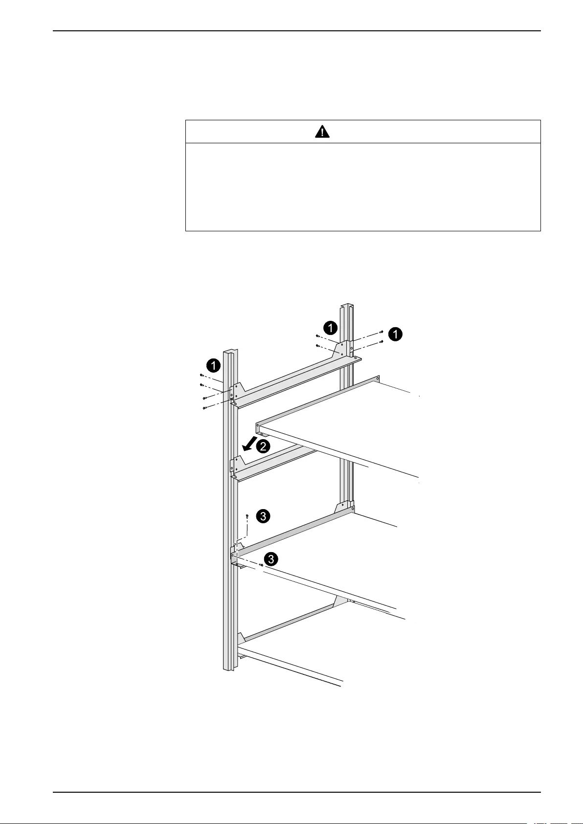
Install Shelves in Galaxy 1900 mm Battery Cabinet
CAUTION
HAZARD OF INJURY OR EQUIPMENT DAMAGE
Assembly of the battery cabinet must be carried out by certified personnel
(standard EN 50091–1–2). The minimum clearance between the top of the
battery cells and the next shelf above them is 150 mm.
Failure to follow these instructions can result in injury or equipment
damage.
1. Secure the angle supports (6 screws per support).
2. Position each shelf.
3. Secure each shelf with two screws in each angle.
990–3618G-001 53
10–40 kVA 3:1 and 3:3 Install Battery Solution
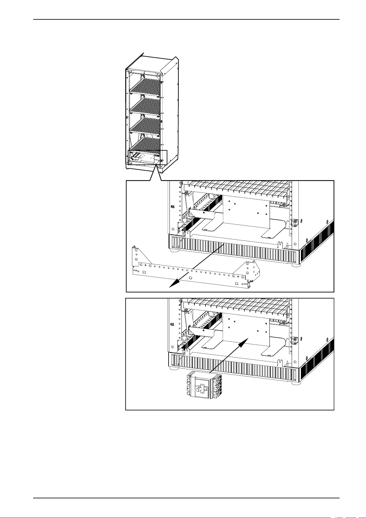
Install Battery Circuit Breaker Kit in Galaxy 1900 mm Battery
Cabinet
DANGER
HAZARD OF ELECTRIC SHOCK, EXPLOSION, OR ARC FLASH
It is mandatory to protect the battery circuit with a circuit breaker equipped with a
coil terminal and an auxiliary contact (min. 24 VDC).
Failure to follow these instructions will result in death or serious injury.
NOTE: For several battery cabinets installed, only one battery circuit breaker is
necessary. Temperature sensors must be installed to obtain battery warranty and
to optimize battery lifetime.
1. Loosen the two screws on the battery circuit breaker and remove the top cover
(save the two screws for later).
2. Cut a hole in the plastic cover for cable access.
3. Install the battery circuit breaker auxiliary parts 530-2213 and 540-0274.
4. Connect the white, yellow, black, and red ATIZ cables to the terminals on the
auxiliary parts and note the mark and color of the cables.
5. Reinstall the plastic cover on the battery circuit breaker with the two screws.
Cable description
Cable color Cable label Description
Yellow QB OF-11 CB contact signal – to the auxiliary contact
(normally closed)
White QB OF-14 CB contact signal
Red QB OF-D4 +12 V power supply – to the coil terminal
Black QB OF-D1 -12 V power supply
54 990–3618G-001
Install Battery Solution 10–40 kVA 3:1 and 3:3
6. Install the battery circuit breaker on the preinstalled plate in the bottom of the
battery cabinet. The front metal plate and the corner triangles can be removed
for easy access.
990–3618G-001 55
10–40 kVA 3:1 and 3:3 Install Battery Solution
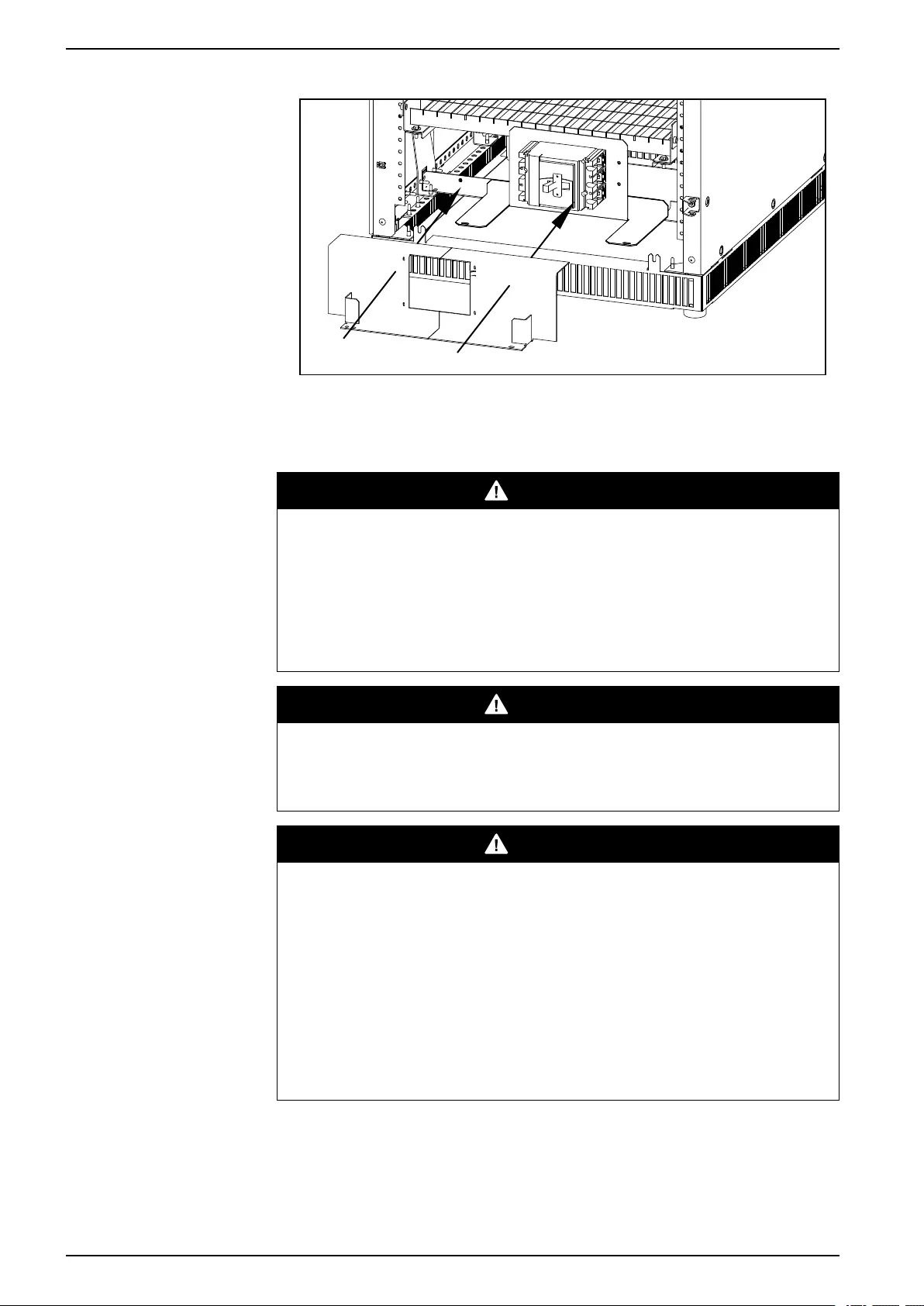
7. Install the two protection covers over the battery circuit breaker.
8. Reinstall the front metal plate and the corner triangles if removed earlier.
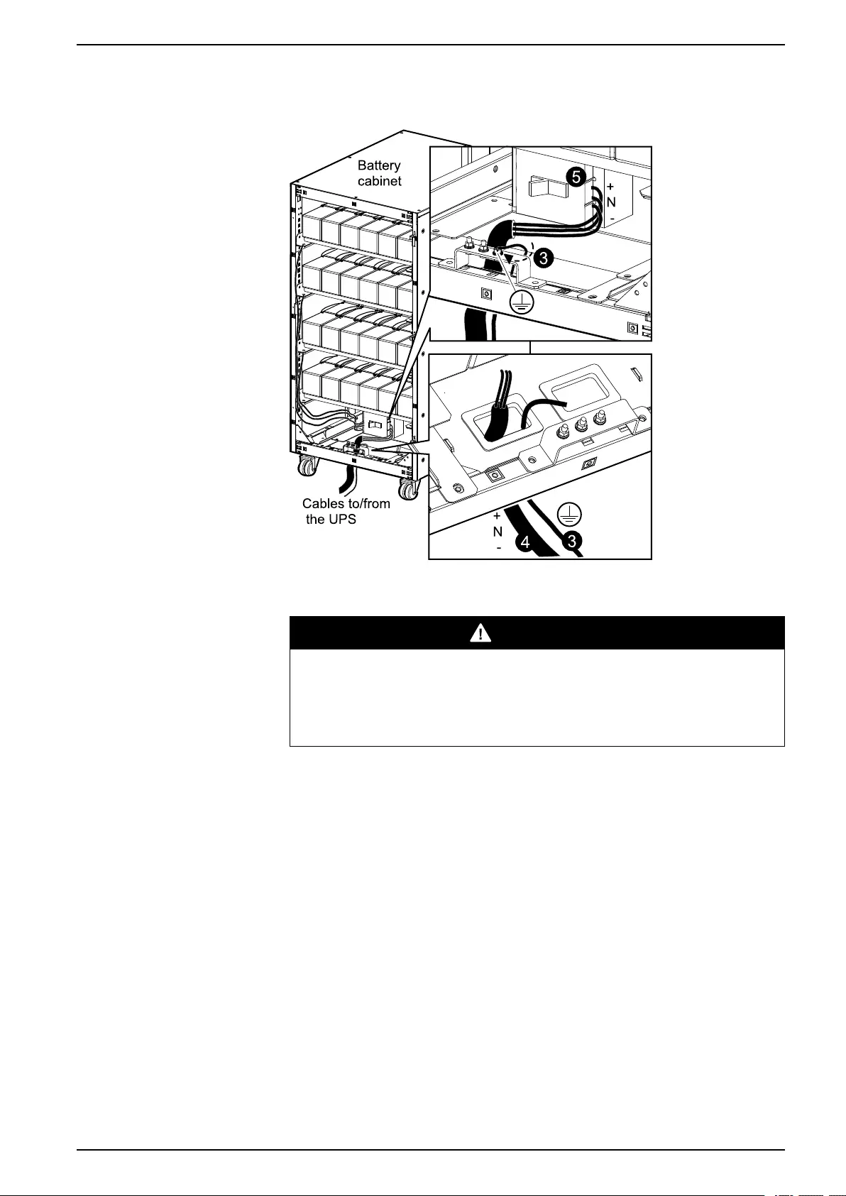
Connect Battery Cables from the UPS to the Galaxy 1900 mm Battery Cabinet
DANGER
HAZARD OF ELECTRIC SHOCK, EXPLOSION, OR ARC FLASH
• Make sure that there are no internal batteries in the UPS before connecting a
battery cabinet to the system.
• Make sure that the battery breaker is open before starting.
• Check the DC voltages with a DC voltage multimeter versus the battery
voltage before continuing.
Failure to follow these instructions will result in death or serious injury.
DANGER
HAZARD OF ELECTRIC SHOCK
The battery cabinet(s) and the UPS must be earthed properly.
Failure to follow these instructions will result in death or serious injury.
DANGER
HAZARD OF ELECTRIC SHOCK, EXPLOSION OR ARC FLASH
• Battery circuit breakers must be installed according to the specifications and
requirements as defined by Schneider Electric.
• Servicing of batteries must only be performed or supervised by qualified
personnel knowledgeable of batteries and the required precautions. Keep
unqualified personnel away from batteries.
• Disconnect charging source prior to connecting or disconnecting battery
terminals.
• Turn the battery circuit breakers OFF before connecting cables to the
terminals.
Failure to follow these instructions will result in death or serious injury.
1. Connect the Protective Earth (PE) cable between the battery cabinet(s) and the
UPS.
2. Install the battery cells on each shelf and secure and interconnect them per
shelf.
56 990–3618G-001
Install Battery Solution 10–40 kVA 3:1 and 3:3
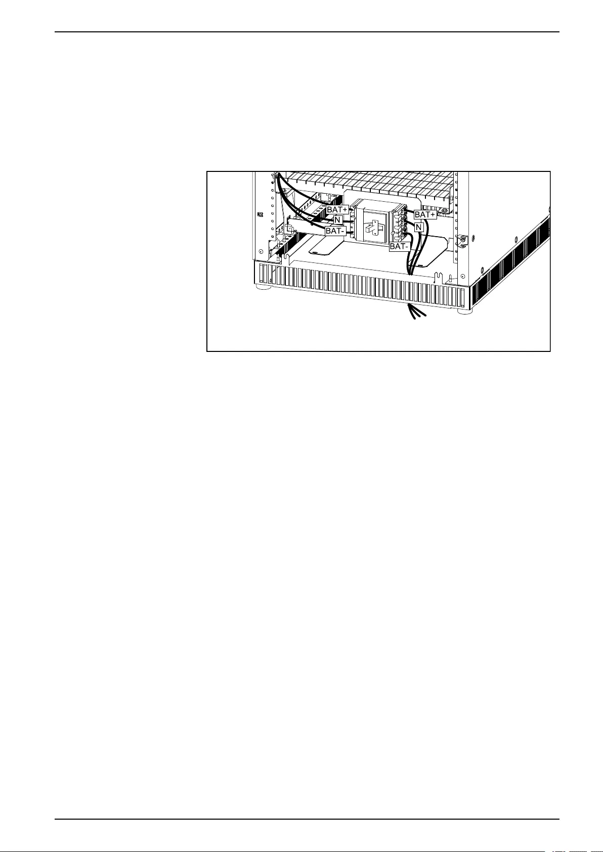
3. Interconnect all the battery shelves and then connect the battery cables (BAT+,
BAT-, N) from the overall battery assembly to the battery circuit breaker in the
battery cabinet as shown in the illustration.
4. If more than one battery cabinet is installed: Connect the BAT+, BAT-, and N
cables (not provided) between the battery cabinets in a daisy chain.
5. Connect the battery cables (BAT+, BAT-, N) from the UPS to the battery circuit
breaker in the battery cabinet that will be connected to the UPS.
Front View of the Battery Cabinet
Install External Battery Temperature (ATIZ) and External Battery Breaker Signal between
the UPS and the Galaxy 1900 mm Battery Cabinet
NOTE: The ATIZ cable is for the external battery temperature detection signal.
NOTE: The battery cable is for the external battery breaker signal.
NOTE: The connection of signal cables is only applicable between the UPS and
battery cabinet 1.
1. Remove the right bottom protection cover on the classic battery cabinet.
2. Connect the cable terminal board to the supplied support sheet metal plate.
990–3618G-001 57
10–40 kVA 3:1 and 3:3 Install Battery Solution
3. Install the cable terminal board in the bottom right side of the battery cabinet
with two screws
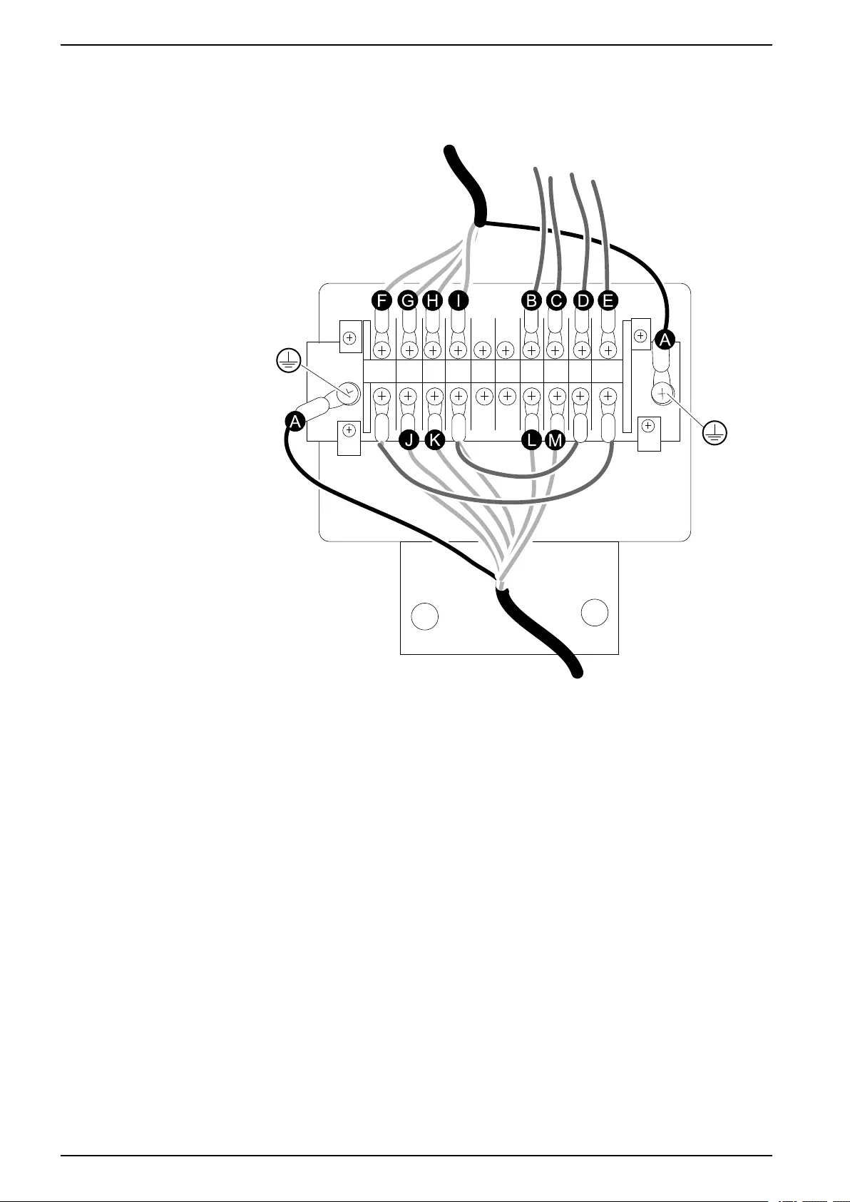
Cable Connection on the Cable Terminal Board
A. PE cables
B. Cable from auxiliary parts in battery circuit breaker (yellow)
C. Cable from auxiliary parts in battery circuit breaker (white)
D. Cable from auxiliary parts in battery circuit breaker (red)
E. Cable from auxiliary parts in battery circuit breaker (black)
F. Cable connected to UPS (black)
G. Cable connected to UPS (white)
H. Cable connected to UPS (green)
I. Cable connected to UPS (red)
J. Cable connected to ATIZ box (white)
K. Cable connected to ATIZ box (green)
L. Cable connected to ATIZ box (yellow)
M. Cable connected to ATIZ box (black)
58 990–3618G-001
Install Battery Solution 10–40 kVA 3:1 and 3:3
4. Connect the four cables from the two auxiliary parts in the circuit breaker to the
cable terminal board.
Cable description
Cable color Cable label Description
Yellow QB OF-11 CB contact signal – to the auxiliary contact
(normally closed)
White QB OF-14 CB contact signal
Red QB OF-D4 +12 V power supply – to the coil terminal
Black QB OF-D1 -12 V power supply
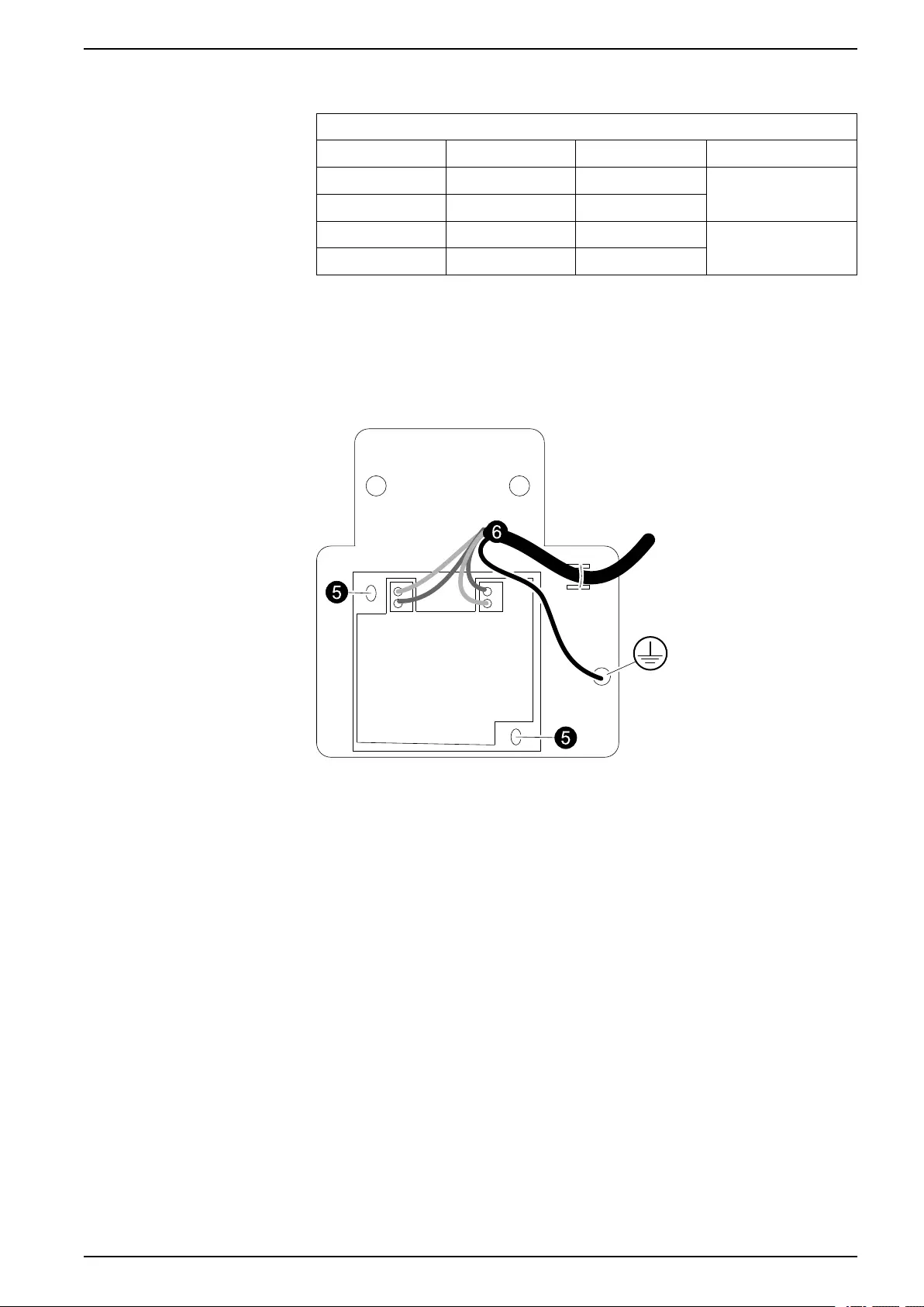
5. Open the ATIZ board box and install it on the supplied support sheet metal plate
with two screws.
6. Connect the four cables and the PE-cable from the cable terminal board to the
ATIZ board. Secure the joining cable with a cable tie.
Cable Connection in the ATIZ Board Box
7. Close the ATIZ board box.
8. Install the ATIZ board box in the top right side of the battery cabinet with two
screws and secure the cable with cable ties down along the inside of the battery
cabinet.
9. Run the combined battery breaker and ATIZ signal cable from the cable
terminal board in the battery cabinet to the UPS.
990–3618G-001 59
10–40 kVA 3:1 and 3:3 Install Battery Solution
10.Connect the combined battery breaker and ATIZ signal cable to the UPS as
shown and make sure to connect the cable with shielded layer to the screw on
the UPS.
NOTE: The cable(s) is routed the same way as the EPO cable.
Rear View of the UPS
11.Reinstall the right bottom protection cover on the battery cabinet.
Connect Battery and Signal Cables to Third Party Battery Solution
DANGER
HAZARD OF ELECTRIC SHOCK, EXPLOSION, OR ARC FLASH
• You must only use the UPS unit version intended for external batteries. A
third party battery solution must ONLY be used for a UPS configured with
long backup time charger (CLA).
• Before carrying out any of the below steps, you must make sure that the UPS
unit and battery unit are powered off. See the operation manual (990-3619)
shipped with the UPS unit on how to power off the UPS via the display.
• The external battery temperature detection kit (ATIZ) and the breaker signal
must be installed to ensure that the battery works normally. If the ATIZ kit is
not installed, the UPS will report a temperature fault with a permanent alarm.
Only a Schneider Electric field service engineer can disable this alarm. The
consequence of not installing the ATIZ kit is that the unit does not have a
temperature compensation function, and this will also affect the battery life, if
the battery is installed in a room that is not appropriately air-cooled.
• The cables must have shielded layer, and they must be connected to the
UPS and the external third party battery solution. If not, the unit will face EMC
and shutdown problems.
• The battery breaker must be equipped with a coil terminal and an auxiliary
contact (min. 24 VDC).
• Schneider Electric is not responsible for the wiring of external third party
batteries.
Failure to follow these instructions will result in death or serious injury.
60 990–3618G-001
Install Battery Solution 10–40 kVA 3:1 and 3:3
NOTE: A maximum of two battery cabinets can be connected to the UPS (one
battery cabinet with a circuit breaker plus one cabinet without a circuit breaker, as
only one breaker is supported) by a batch cable between the UPS and the circuit
breaker in the battery cabinet.
1. Prepare one or two shielded cables with 4 twisted pairs for the ATIZ contact and
the battery circuit breaker. All shielded cables must be wound three times
around a High permeability NiZn Ferrite placed as close to the UPS as possible.
NOTE: +/-12 V power supply is common for ATIZ and the auxiliary coil of the
battery circuit breaker.
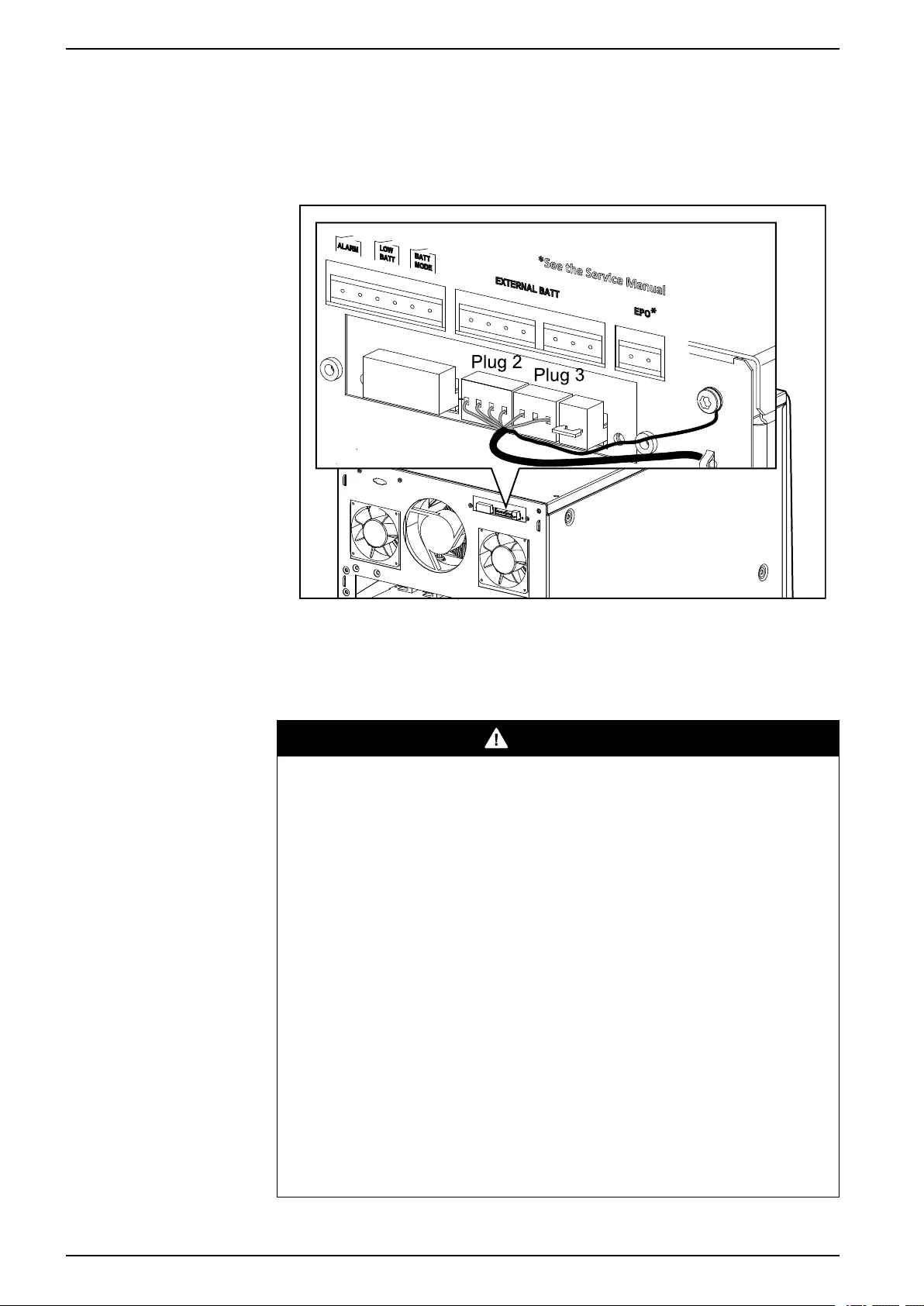
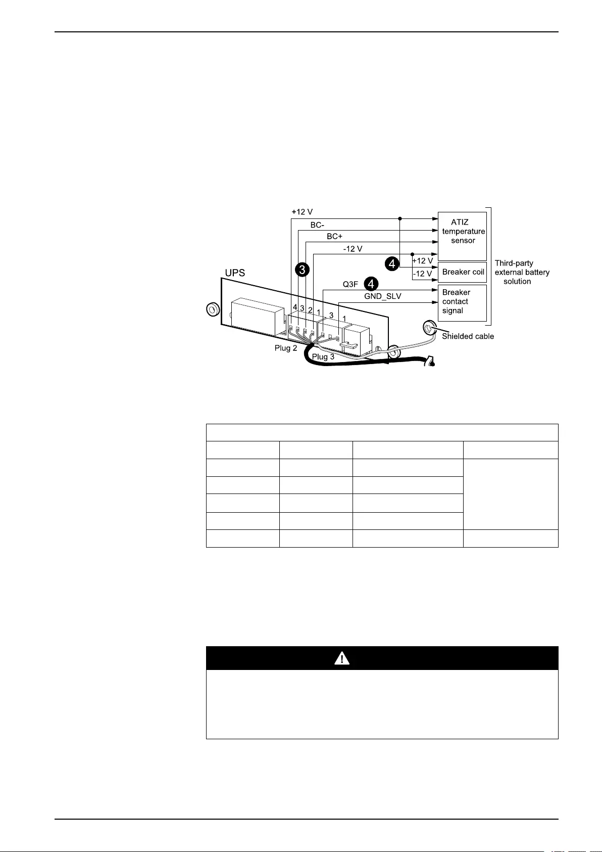
Rear View of the UPS
2. Install the ATIZ signal board in the third party battery solution.
3. Connect the ATIZ signal cable to the ATIZ board in the third party battery
solution (see the below table for cable description).
Cable description
Cable color Cable label Description
Black -12 -12 V power supply – to the ATIZ contact
White BC- BC- (ATIZ signal)
Green BC+ BC+ (ATIZ signal)
Red +12 +12 V power supply
Green-yellow Grounding
NOTE: If a battery breaker has not been installed in the third party battery
solution, install one now. The battery breaker must be equipped with a coil
terminal and an auxiliary contact (min. 24 VDC). If there is no undervoltage coil
terminal in the battery circuit breaker, then the UPS cannot open the battery
circuit breaker when necessary (EPO). If there is no auxiliary contact in the
battery circuit breaker, then the UPS will report a battery circuit breaker open
fault with a permanent alarm.
DANGER
HAZARD OF ELECTRIC SHOCK, EXPLOSION, OR ARC FLASH
The battery circuit breaker must be open (in the OFF position) before you
connect the cables.
Failure to follow these instructions will result in death or serious injury.
990–3618G-001 61
10–40 kVA 3:1 and 3:3 Install Battery Solution
4. Connect the battery breaker signal cable from the UPS to the battery circuit
breaker in the third party battery solution (see the below table for cable
description).
Cable description
Cable color Cable label Description
Yellow QB OF-11 CB contact signal – to the auxiliary contact
(normally closed)
White QB OF-14 CB contact signal
Red QB OF-D4 +12 V power supply – to the coil terminal
Black QB OF-D1 -12 V power supply
5. Attach Protective Earth (PE) cable from the UPS to the battery solution, and
connect the battery cables (BAT+, N, BAT-) from the UPS to the battery circuit
breaker in the third party battery solution. See Recommended Cable Sizes,
page 15.
62 990–3618G-001
Connect the UPS Signal Cables 10–40 kVA 3:1 and 3:3
Connect the UPS Signal Cables
Connect the Signal Cables to the UPS
1. Open the front door.
2. Connect the shielded signal cables (optional) to the Network Management
Card. Refer to the Network Management Card documentation shipped with the
UPS.
3. Connect the UPS backfeed signal CNR04-1 CNR04-2.
Front View of the UPS
4. Run the cables through the slot (otherwise the door cannot close) and up along
the right side of the cabinet.
990–3618G-001 63
10–40 kVA 3:1 and 3:3 Connect the UPS Signal Cables
5. Fasten the cables with cable ties.
Front View of the UPS
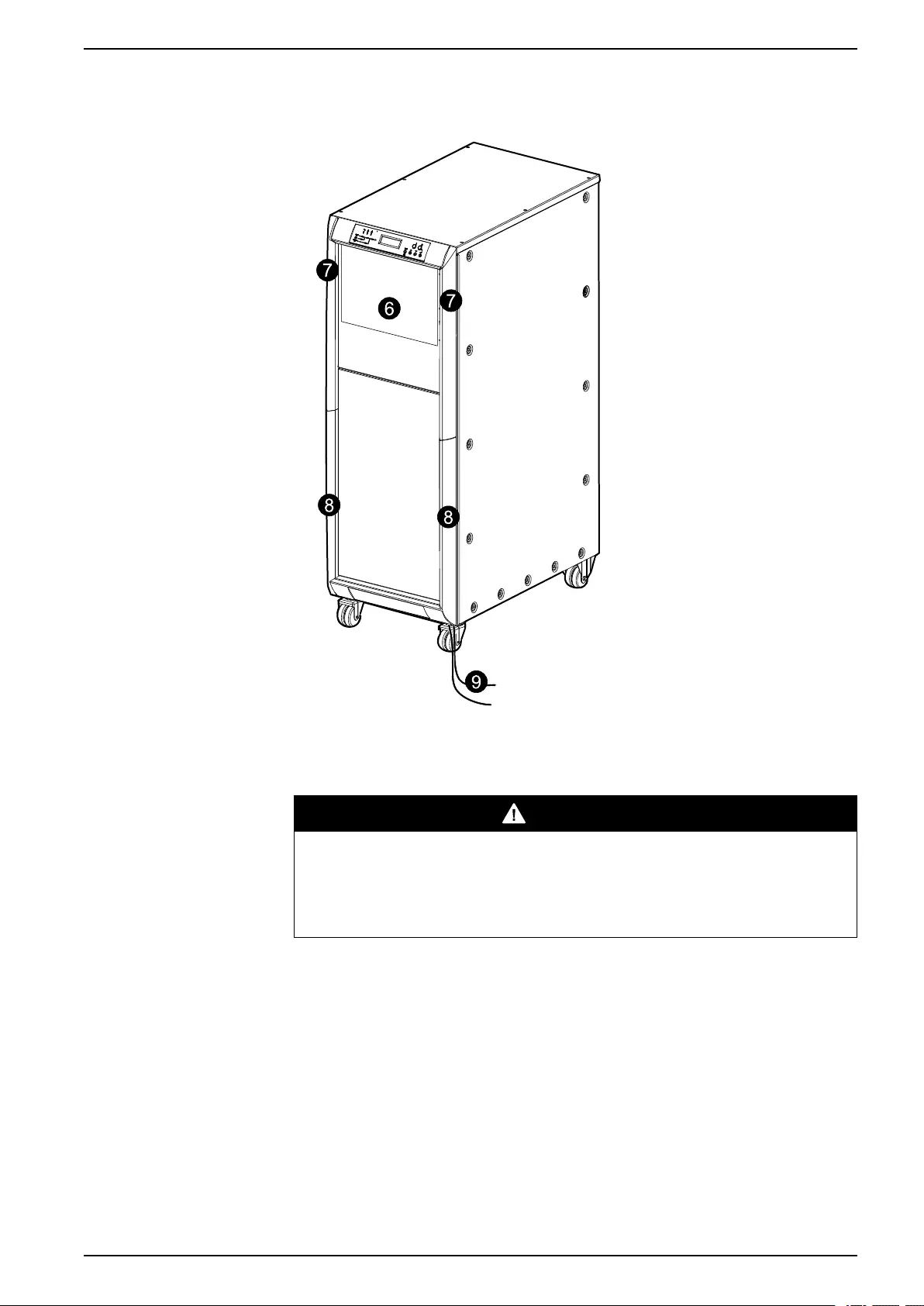
6. Close the upper front door by pushing the door in.
7. Install the two upper side covers with two hands by tipping the covers 10º. Then
push down the two clips on the covers (3 mm down) in the rectangular holes on
the front panel, and then push in the covers.
8. Install the two bottom side covers in the same way.
64 990–3618G-001
Connect the UPS Signal Cables 10–40 kVA 3:1 and 3:3
9. Connect the cables to your computer interface network.
Front View of the UPS
Connect the EPO Cable to the UPS
DANGER
HAZARD OF ELECTRIC SHOCK, EXPLOSION, OR ARC FLASH
The cables must have a shielded layer, and the shielded layer must be
connected to grounding on both the UPS side and the customer side.
Failure to follow these instructions will result in death or serious injury.
NOTE: A jumper must be added if no EPO cable is connected.
990–3618G-001 65
10–40 kVA 3:1 and 3:3 Connect the UPS Signal Cables
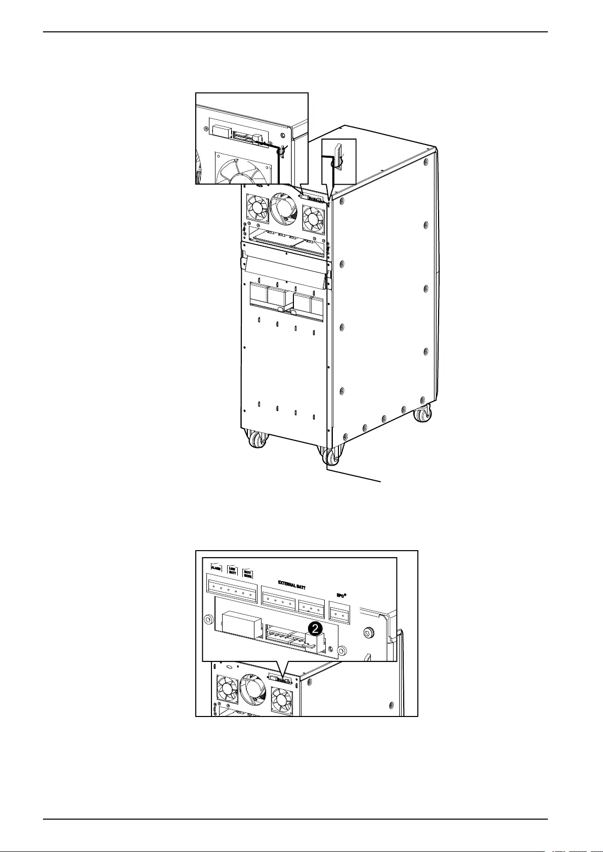
1. Route a shielded EPO cable and optional signal cables.
Rear View of the UPS
2. Connect the Emergency Power Off (EPO) with a shielded cable to the pin
(cable not provided). The default connection is closed with two pins.
Rear View of the UPS
66 990–3618G-001
Connect the UPS Signal Cables 10–40 kVA 3:1 and 3:3
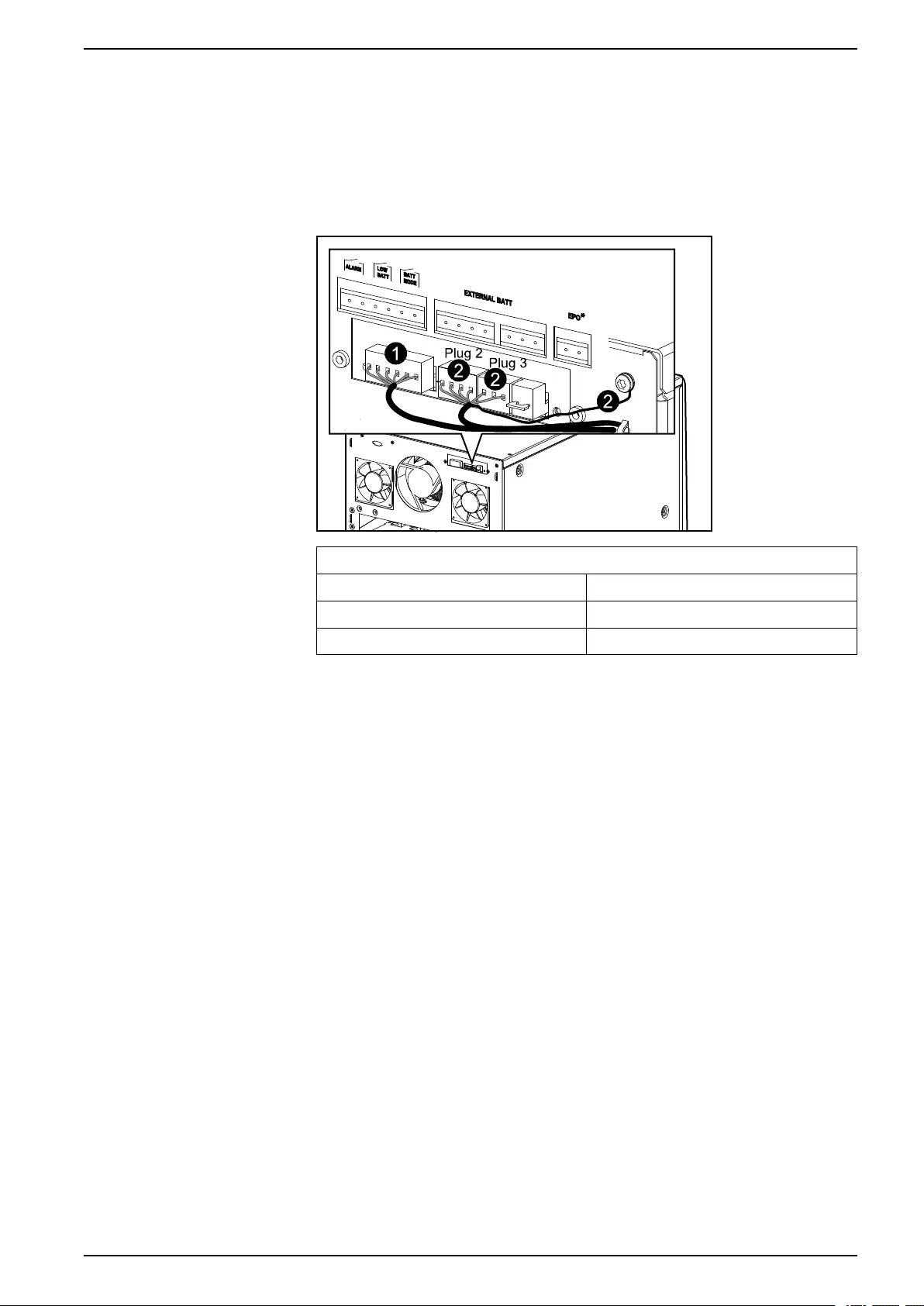
Connect the Optional Signal Cables
1. Connect the dry connector with a shielded cable (cable not provided). The dry
contacts permit to monitor the UPS from external relay switches regarding
general alarms, battery mode, and low battery. Run the cables to an indication
instrument such as LEDs, etc.
Rear View of the UPS
Requirements for dry connector cables
Permissible voltage (VDC) 30
Permissible current (A) 1
Cable 4 x 0.93 mm², ø 6.6 ± 0.3 mm.
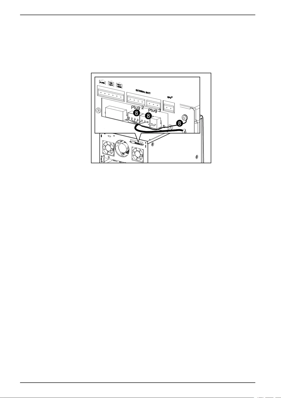
2. If external batteries are used, connect the cable for the external battery
temperature detection and the external battery circuit breaker signal to signal
ports 2 and 3.
NOTE: If the Galaxy 300 battery cabinet (1300 mm) is used, one cable end is
pre-installed in this battery cabinet. If a third party battery solution is used, see
Connect Battery and Signal Cables to Third Party Battery Solution, page 60.
NOTE: Parallel cabling must be carried out by Schneider Electric. Up to two
units can run in parallel with a mutual distance of up to 12 m (two cables of 5
and 15 m are provided in the parallel kit).
990–3618G-001 67

10–40 kVA 3:1 and 3:3 Checklist after Installation
Checklist after Installation
UPS
• Check that the power wiring is torqued correctly.
• Verify clockwise phase-rotation (L1, L2, L3) and make sure that a neutral
connection is present.
• Leave a wiring diagram on site for service personnel.
• Reinstall all wiring access panels.
• Make sure that all battery breakers on the UPS unit are in the OFF (opened)
position.
Battery Solution
• Check that the power wiring is torqued as recommended by the battery vendor.
• Verify the polarity of battery cable connection (BAT+, N and BAT-).
• Leave a wiring diagram on site for service personnel.
• Reinstall all wiring access panels.
• Make sure that all battery breakers on the battery solution are in the OFF
(opened) position.
• Install the two protection covers over the battery circuit breaker on the Galaxy
1900 mm battery cabinet.
68 990–3618G-001


Printed in.
Schneider Electric
Schneider Electric
35 rue Joseph Monier
92500 Rueil Malmason
France
+ 33 (0) 1 41 29 70 00
www.schneider-electric.com
As standards, specifications, and design change from time to time,
please ask for confirmation of the information given in this publication.
© 2012 – 2016 Schneider Electric. All rights reserved.
990–3618G-001
- Categories
- Brands
-
Home
-
APC
-
Software
-
MGE Galaxy 300
Owner’s manuals and user’s guides for Software APC MGE Galaxy 300.
We providing 1 pdf manuals APC MGE Galaxy 300 for download free by document types: User’s Guide

Table of contents
MGE Galaxy 300 — Simplicity you can trust.
The MGE Galaxy
™
300 provides an effective and reliable solution for
protecting small server rooms, commercial buildings, and technical facilities.
The online, double-conversion topology supplies true isolation between
input and output with a zero transfer time. Up to 30 minutes of integrated
battery back-up, internal mechanical bypass and parallel capability allows
for higher levels of availability. Remote and local monitoring/management
capability is achieved through a built-in communication card with a simple
Web/SNMP interface and a user-friendly display available in 18 languages.
Both 3:3- and 3:1-phase configurations are available for convenient power
distribution. Serviceability is greatly enhanced by front access for ease
of maintenance in confined spaces. All of these features, along with the
included start-up services and on-site warranty, make the MGE Galaxy 300
the easiest UPS in its class to install, manage, and maintain.
MGE Galaxy 300
3:3-phase: 10/15/20/30/40 kVA, 3:1-phase: 10/15/20/30 kVA
Effective and reliable three-phase power protection designed to
prevent downtime and data loss for mission-critical applications.

MGE Galaxy 300 20 кВА 3:1
1
Плата связи (только для
сервисного обслуживания APC
by Schneider Electric)
2
Сетевая плата управления
(NMC)
3
Выключатели
4
Батарейные полки
5
Сухой разъем, аварийный
выключатель питания, сигнал
выключателя внешних батарей
и температура внешних батарей
(ATIZ)
6
Клеммы питания
MGE Galaxy 300 10/15 кВА 3:1
1
Плата связи (только для
сервисного обслуживания APC
by Schneider Electric)
2
Сетевая плата управления
(NMC)
3
Выключатели
4
Батарейные полки
5
Сухой разъем, аварийный
выключатель питания, сигнал
выключателя внешних батарей
и температура внешних батарей
(ATIZ)
6
Клеммы питания
Параллельная система
Устройство MGE Galaxy 300 можно установить в параллели с не более чем двумя ИБП. Установите
оба устройства ИБП по отдельности, как указано в настоящем руководстве. Параллельное
соединение между двумя ИБП может выполняться только сервисным инженером компании
APC by Schneider Electric, причем комплекты для параллельного подключения приобретаются
отдельно. Информация о параллельных системах: “Оценка площадки“ и “Крепление к полу
(необязательно)“.
990–3618E-028
MGE™ Galaxy™ 300 380/400/415 V Установка
13

Общие сведения: системы ИБП MGE™ Galaxy™ 300
Плата связи плата сетевого управления выключатели и батарейные полки расположены за передней дверцей; для доступа к ним необходимо слегка надавить на белый круг в правой части дверцы Разъемы и клеммы питания расположены на задней панели.
MGE Galaxy 300 30/40 кВА 3:3
Плата связи (только для сервисного обслуживания APC by Schneider Electric)
Сетевая плата управления (NMC)
Выключатели
Батарейные полки
Сухой разъем аварийный выключатель питания сигнал выключателя внешних батарей и температура внешних батарей (ATIZ)
Клеммы питания
990–3618E-028
MGE™ Galaxy™ 300 380/400/415 V Установка

MGE Galaxy 300 30 кВА 3:1
1
Плата связи (только для
сервисного обслуживания APC
by Schneider Electric)
2
Сетевая плата управления
(NMC)
3
Выключатели
4
Батарейные полки
5
Сухой разъем, аварийный
выключатель питания, сигнал
выключателя внешних батарей
и температура внешних батарей
(ATIZ)
6
Клеммы питания
MGE Galaxy 300 10/15/20 кВА 3:3
1
Плата связи (только для
сервисного обслуживания APC
by Schneider Electric)
2
Сетевая плата управления
(NMC)
3
Выключатели
4
Батарейные полки
5
Сухой разъем, аварийный
выключатель питания, сигнал
выключателя внешних батарей
и температура внешних батарей
(ATIZ)
6
Клеммы питания
12
MGE™ Galaxy™ 300 380/400/415 V Установка
990–3618E-028