
Назначение
Описание
Программное обеспечение
Технические характеристики
Знак утверждения типа
Комплектность
Поверка
Сведения о методах измерений
Нормативные документы
Назначение
Анализаторы влажности «Ametek» модели 5000 с системой подготовки пробы (далее -анализаторы) предназначены для измерений объемной доли влаги в газе в составе системы измерений количества и показателей качества свободного нефтяного газа с Ярудейского месторождения ООО «Яргео». Анализаторы обеспечивают пересчет объемной доли влаги в температуру точки росы/инея (для чистых газов, не содержащих компонентов, влияющих на погрешность пересчета).
Описание
Принцип действия анализаторов основан на измерении разности частот кварцевого генератора, размещенного в измерительной ячейке, при поочередном прохождении через ячейку анализируемого влажного газа и сравнительного, в качестве которого используется осушенный анализируемый газ. Кварцевый генератор содержит покрытый пленкой гигроскопического материала кристалл. В зависимости от влажности газа, пленочное покрытие кристалла поглощает или отдает влагу, в результате чего происходит изменение собственной частоты колебаний кристалла. Разность частот кварцевого генератора, при прохождении анализируемого и сухого газов, пропорциональна объемной доле влаги в газе. На основании измерений объемной доли влаги в газе вычисляется температура точки росы/инея по ГОСТ 8.547-2009.
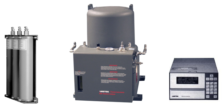
В состав каждого анализатора входят:
— полевой блок с измерительной ячейкой с асимметричным циклом;
— встроенный генератор влажности 20 млн-1;
— ловушка загрязнений;
— внешний осушитель с молекулярными ситами 0,3 нм;
— блок управления 5000 общепромышленного исполнения;
— пузырьковый расходомер;
— система подготовки пробы производства ЗАО НИЦ «ИНКОМСИСТЕМ».
Встроенный генератор влажного газа представляет собой тефлоновую проницаемую трубку, погруженную в резервуар с водой.
В качестве сравнительного газа используется осушенный анализируемый газ, подготовленный с помощью системы отбора и подготовки пробы
Измерительная ячейка, генератор влажности, соленоидные клапаны, регуляторы давления и диафрагмы с калибровочными отверстиями для стабилизации расхода газа помещены в термостат, в котором поддерживается температура 60 °С. Управление функциями анализатора обеспечивается микропроцессором.
В состав каждой системы подготовки пробы входят:
— система прецизионного редуцирования;
— фильтр угольный;
— осушители с высокой степенью активности;
— байпасный пузырьковый расходомер;
— эжектор;
— запорно-регулирующая арматура;
— соединительные трубопроводы.
Назначение составных частей:
— система редуцирования анализируемого газа снижает давление до необходимого уровня;
— фильтр угольный предназначен для очистки газа от вероятной жидкой фазы углеводородов и от возможных технологических примесей;
— осушители предназначены для глубокой осушки газа в целях обеспечения восстановления измерительной ячейки в исходное (обезвоженное) состояние и обеспечения представительной градуировки по внутреннему стандарту;
— пузырьковый расходомер предназначен для измерения расхода газа по байпасной линии в целях обеспечения эффективной работы эжектора;
— эжектор на выходе прибора предназначен для стабилизации давления в измерительной ячейке прибора, и для исключения обратной диффузии атмосферной влаги в тракт;
— запорно-регулирующая арматура включает в себя манометр для измерения давления пробы газа, отсечные и трехходовые краны для коммутации газовых линий.
Фотографии общего вида приведены на рисунках 1 и 2.
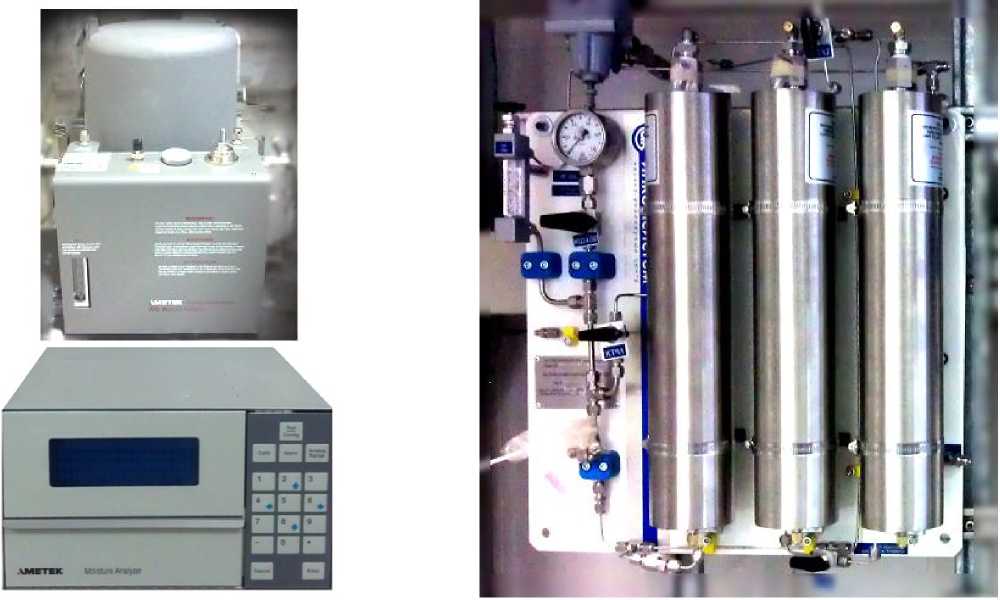
Рисунок 1 — Анализатор влажности газа Рисунок 2 — Система подготовки пробы
Ametek 5000 с блоком управления
Пломбирование корпуса анализаторов осуществляется в месте установки стопорного винта нанесением знака поверки в виде наклейки или давлением на специальную мастику.
Место пломбирования анализаторов приведено на рисунке 3.
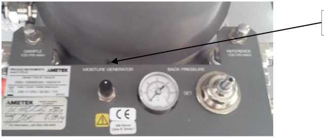
Место пломбирования
Рисунок 3 — Место пломбирования стопорного винта на корпусе анализаторов
Программное обеспечение
Программное обеспечение является встроенным. Программное обеспечение (далее — ПО) анализаторов служит для реализации функций анализаторов. Защита информационных данных от непреднамеренных и преднамеренных изменений и обеспечение его соответствия утвержденному типу, осуществляется путем аутентификации (введением пароля), идентификации: отображения на информационном дисплее анализатора структуры идентификационных данных, содержащей номер версии ПО. Цифровые интерфейсы связи отсутствуют. ПО анализатора имеет уровень защиты «средний» по Р 50.2.077-2014.
Идентификационные данные ПО анализаторов приведены в таблице 1.
Таблица 1 — Идентификационные данные ПО анализаторов
|
Идентификационные данные (признаки) |
Значение |
|
Идентификационное наименование ПО |
— |
|
Номер версии (идентификационный номер ПО) |
1.04 |
|
Цифровой идентификатор ПО |
— |
|
Цифровой идентификатор конфигурации ПО |
— |
Технические характеристики
Таблица 2 — Метрологические и технические характеристики анализаторов
|
Наименование |
Значение характеристики |
|
Диапазон измерений объемной доли влаги, млн-1 |
от 1 до 1000 |
|
Пределы допускаемой относительной погрешности измерений объемной доли влаги в анализируемом газе в следующих поддиапазонах: — от 1 до 10 млн-1 включ., % — св. 10 до 100 млн-1 включ., % — св. 100 до 1000 млн-1, % |
±8,0 ±5,0 ±5,0 |
|
Пределы допускаемой абсолютной погрешности расчета температуры точки росы анализируемого газа в диапазоне температуры от минус 60 до плюс 30°С, не более, °С |
±1,0 |
|
Потребляемая мощность, кВт, не более |
1 |
|
Условия эксплуатации: — температура окружающей среды, °С — полевой блок — блок управления — температура в системе пробоотбора, °С — атмосферное давление, кПа — относительная влажность, % |
от — 20 до + 50 от 0 до + 50 от — 40 до + 50 от 84 до 106 до 95, без конденсации влаги |
|
Параметры электропитания: — напряжение, В: — частота, Гц |
230±10 50±1 |
|
Габаритные размеры, мм — полевой блок — блок управления — система подготовки пробы |
320x420x400 230x130x320 500x600x150 |
|
Наименование |
Значение характеристики |
|
Масса, кг, не более — полевой блок |
34 |
|
— блок управления |
5 |
|
— система подготовки пробы |
12 |
|
Средний срок службы, лет, не менее |
16 |
Знак утверждения типа
наносится методом шелкографии на маркировочную табличку, закрепленную на блок управления, и на титульный лист паспорта типографским способом.
Комплектность
Комплектность анализаторов представлена в таблице 3.
Таблица 3 — Комплектность анализаторов
|
Наименование |
Количество |
|
Анализатор влажности «Ametek» модели 5000 с системой подготовки пробы, заводской № 05-2801-2015, состоящий из: — анализатор влажности «Ametek», заводской № 500А413; — система подготовки пробы «Система измерения влажности газа», № 03-2801-2015 |
1 |
|
Анализатор влажности «Ametek» модели 5000 с системой подготовки пробы, заводской № 06-2801-2015, состоящий из: — анализатор влажности «Ametek», заводской № 500А414 — система подготовки пробы «Система измерения влажности газа», № 04-2801-2015 |
1 |
|
«Анализатор влажности «Ametek» модели 5000 с системой подготовки пробы». Паспорт |
1 |
|
«ГСИ. Анализаторы влажности «Ametek» модели 5000 с системой подготовки пробы». Методика поверки |
1 |
|
«Анализаторы влажности «Ametek» модели 5000 с системой подготовки пробы». Руководство по эксплуатации |
1 |
Поверка
осуществляется по документу МП 65491-16 «ГСИ. Анализаторы влажности «Ametek» модели 5000 с системой подготовки пробы. Методика поверки», утвержденному ФГУП ВНИИФТРИ 9 апреля 2015.
Основные средства поверки:
— генератор влажного газа Родник-4М, диапазон воспроизводимой объемной доли влаги от 0 до 460000 млн-1, 1 разряд по ГОСТ 8.547-2009;
— гигрометр кулонометрический БАЙКАЛ-МК, диапазоны измерений объемной доли влаги от 1 до 10 млн-1, от 10 до 100 млн-1, от 100 до 1000 млн-1, пределы допускаемой относительной погрешности объемной доли влаги по цифровому табло и выходному унифицированному сигналу ±4 % для диапазона от 1 до 10 млн-1, ±2,5 % для диапазонов от 10 до 100 млн-1 и от 100 до 1000 млн-1.
Допускается применение аналогичных средств поверки, обеспечивающих определение метрологических характеристик поверяемых СИ с требуемой точностью.
Знак поверки наносится на свидетельство о поверке анализаторов, а также на пломбы, установленные в соответствии с рисунком 3.
Сведения о методах измерений
Методика измерений изложена в руководстве по эксплуатации на анализаторы влажности «Ametek» модели 5000 с системой подготовки пробы
Нормативные документы
ГОСТ 8.547-2009 «ГСИ. Государственная поверочная схема для средств измерений влажности газов».
Техническая документация ЗАО НИЦ «ИНКОМСИСТЕМ».
 |
[Page 1] Ametek 5000 5000 Moisture Analyzer with Multi-Point Analysis Instrument Manual 500092901, Rev.T Process Instruments 455 Corporate Boulevard Newark, DE 19702, USA |
 |
[Page 2] Ametek 5000 ii 5000 Multi Point Moisture Analyzer © 2000 AMETEK This manual is a guide for the use of the Model 5000 Moisture Analyzer (Multi-Point). Data herein has been verified and validated and is believed adequate for the intended use of this instrument…. |
 |
[Page 3] Ametek 5000 iii Table of Contents Safety Notes ……………………………………………………………………………………………vi Overview Theory of Operation ………………………………………………………………….. |
 |
[Page 4] Ametek 5000 iv 5000 Multi Point Moisture Analyzer Software Configuration Level 2 Configure Menu …………………………………………………………………. 4-1 Constants …………………………………………………………….. |
 |
[Page 5] Ametek 5000 v Wiring Module Schematic ………………………………………………………………. 7-9 Dual Current Output Schematic ……………………………………………………..7-12 Appendix A: Miscellaneous Options Asymmetric… |
 |
[Page 6] Ametek 5000 vi 5000 Multi Point Moisture Analyzer Safety Notes Warnings, cautions, and notes within the text of this manual emphasize important and critical instructions as follows: An operating procedure or practice which, if not strictly observed, could resu… |
 |
[Page 7] Ametek 5000 vii Sample Gas Potential hazards of the sample gas should be taken into consideration before connecting sample to the analyzer. Personal protective equipment and proper ventilation must be used if sample is toxic or corrosive. Eliminate all fire ha… |
 |
[Page 8] Ametek 5000 viii 5000 Multi Point Moisture Analyzer Warning Labels These symbols may appear on the instrument in order to alert you of conditions that exist. PROTECTIVE CONDUCTOR TERMINAL (BORNIER DE L’ECRAN DE PROTECTION) Schutzerde CAUTION — Risk of electri… |
 |
[Page 9] Ametek 5000 ix SPECIAL WARNINGS AND INFORMATION FOR USE OF THE 5000 CONTROLLER IN HAZARDOUS LOCATIONS This equipment is suitable for use in Class I, Division 2, Groups ABCD or Non-Hazard- ous Areas Only. Warning — Explosion Hazard — Substitution of components m… |
 |
[Page 10] Ametek 5000 x 5000 Multi Point Moisture Analyzer This page intentionally left blank. |
 |
[Page 11] Ametek 5000 Overview 1-1 * Timing for typical 5000 system only. Refer to Appendix A for timing of units with asymmetric cycle. OVERVIEW The AMETEK 5000 Moisture Analyzer System measures trace concentrations of moisture in gases such as hydrogen, natural gas,… |
 |
[Page 12] Ametek 5000 1-2 5000 Multi Point Moisture Analyzer Figure 1: 5000 Moisture Analyzer Block Diagram |
 |
[Page 13] Ametek 5000 Overview 1-3 Figure 2: 5000 Analyzer Gas Flow Diagram SAMPLE REFERENCE MOISTURE GENERATOR EXHAUST DENOTES EQUIPMENT MARKING ENERGIZED (N.C. POSITION DE-ENERGIZED (N.O. POSITION) EXHAUST FLOWMETER SUPERACTIVATED DRYER (OPTIONAL) MOLECULAR SIEVE … |
 |
[Page 14] Ametek 5000 1-4 5000 Multi Point Moisture Analyzer Gas Flow (Figure 2) Gas flows in three separate streams through the system: sample gas, reference gas, and moisture generator gas. Flow rate through the cell (for whichever gas is present) is controlled by fl… |
 |
[Page 15] Ametek 5000 Overview 1-5 Figure 3: Typical 5000 Field Unit Top View Back View Flowmeter Sample Gas Inlet Sample Gas Flow Control Moisture Generator Flow Controll Power and Electronics Control PC Board Reference Gas Inlet Reference Gas Flow Control Back Pre… |
 |
[Page 16] Ametek 5000 1-6 5000 Multi Point Moisture Analyzer Externally mounted controls and indicators: • Sample gas flow control • Reference gas flow control • Moisture generator flow control regulator • Flowmeter • Back pressure regulator control • B… |
 |
[Page 17] Ametek 5000 Overview 1-7 *Unless ordered as an extended range configuration. SPECIFICATIONS Ranges • Calibrated 0 to 1000 parts per million by volume (ppmv) • Display continues to provide trend information above 1000 ppmv. • Output capability… |
 |
[Page 18] Ametek 5000 1-8 5000 Multi Point Moisture Analyzer Voltage and Power Requirements All systems are available with choice of nominal AC voltages: Field Unit: • 100 ±10%, 50/60 Hz, 175W max. • 115 ±10%, 50/60 Hz, 175W max. • 230… |
 |
[Page 19] Ametek 5000 Installation 2-1 INSTALLATION Read this section of the manual before beginning installation of the 5000 Analyzer System. Fail- ure to do so, and /or use of the Analyzer in a manner not specified in this manual, may impair the protection against fir… |
 |
[Page 20] Ametek 5000 2-2 5000 Multi Point Moisture Analyzer Figure 4: Installation / Dimensional Layout for 5000 Field Unit GROUNDING LUG 3/4-14 NPT, 2 HOLES SEE NOTE 2 GROUND CONNECTION LOCATED BEHIND TB1 GENERATOR FLOW ADJUSTMENT BACK PRESSURE GAUGE FLOWMETER CENELEC … |
 |
[Page 21] Ametek 5000 Installation 2-3 Figure 5a: Installation / Dimensional Layout for Surface Mounted 5000 Controller (.50) 13 (0.44) 11 (5.25) 133 (5.25) 133 (9.1) 231 (1.2) 31 (.63) 16 (10.25) 260 (10.38) 264 (7.62) 194 (5.38) 137 (11.50) 292 (11.38) 289 (0.4) 10 7.3… |
 |
[Page 22] Ametek 5000 2-4 5000 Multi Point Moisture Analyzer Figure 5b: Installation / Dimensional Layout for 19 inch (~48.26 cm) Rack Mounted 5000 Controller (5.25) 133 (4.95) 126 (1.48) 38 (2.25) 57 (0.4) 10 (12.6) 320 (0.5) 13 (0.25) 6 (9.1) 231 (19.0) 483 HIGH UNITS … |
 |
[Page 23] Ametek 5000 Installation 2-5 Figure 5c: Installation / Dimensional Layout for Through Panel Mounted 5000 Controller (0.12) 3 (12.4) 316 (0.3) 7.6 (0.25) 6.4 (10.0) 254 (9.5) 241 (5.6) 142 (9.1) 231 (6.57) 167 (5.25) 133 (0.52) 13.2 (10.45) 266 LG 38 4 PLCS (1.5… |
 |
[Page 24] Ametek 5000 2-6 5000 Multi Point Moisture Analyzer Figure 5d: Installation / Dimensional Layout for Surface Mounted 5000 Controller in NEMA 4X Enclosure (10.00) 254 (12.55) 319 (14.55) 369 (14.94) 379 (8.31) 211 138 (0.51)(0.31) X SLOT, 4 PLCS FRO… |
 |
[Page 25] Ametek 5000 Installation 2-7 Figure 5e: ATEX Zone 1 Enclosure |
 |
[Page 26] Ametek 5000 2-8 5000 Multi Point Moisture Analyzer Figure 5f: Proper and Improper Protective Ground Connections Sole Purpose Ground Stud Chassis CIRCUIT GROUND TERMINAL RING RING TONGUE GROUND STUD SOLE PURPOSE (TOOTH IF ON PAINT) LOCKWASHER NUT MAIN GROUND INC… |
 |
[Page 27] Ametek 5000 Installation 2-9 Power Requirements The 5000 System components are shipped according to the customer order and are fused and set for the voltage of the required mains power. The power requirements are stated near the power entry for the component … |
 |
[Page 28] Ametek 5000 2-10 5000 Multi Point Moisture Analyzer these requirements, the power connections must have the following characteristics: • The installation must include a separate disconnect device, such as a switch or circuit breaker, included as part of the… |
 |
[Page 29] Ametek 5000 Installation 2-11 Figure 6: Interconnecting Wiring Diagram for 5000 Field Unit and 5000 Controller (with Multi-Point and Auto Verification) |
 |
[Page 30] Ametek 5000 2-12 5000 Multi Point Moisture Analyzer Figure 7: 5000 Controller Back Panel Connections |
 |
[Page 31] Ametek 5000 Installation 2-13 Sample System Sample Tap To ensure sample is free of contaminants from the walls of the sample pipeline, a probe extend- ing into the pipe is recommended. The probe tip should be cut to a 45° angle and located about 20-30% into… |
 |
[Page 32] Ametek 5000 2-14 5000 Multi Point Moisture Analyzer Sample Lines & Connections Cleaned and passivated 316L stainless steel* with 0.125 to 0.25 in. OD sample line tubing is recommended for use throughout the sample system. Note that ordinary stainless steel… |
 |
[Page 33] Ametek 5000 Installation 2-15 Molecular Sieve Dryer (1 to 2 ppm) Super-activated Molecular Sieve Dryer ~ 0.1 ppm (Optional) Contaminant Trap (Optional) REFERENCE SAMPLE Field Unit Probe Sample Switching Valves (See Detail, Figure 9c) Pressure Reducer Main Sampl… |
 |
[Page 34] Ametek 5000 2-16 5000 Multi Point Moisture Analyzer • Conditioned Sample Gas Used As Reference Configure sample system as shown in Figure 9a. Standard and optional conditioning compo nents (dryers, contaminant traps) should be strapped in the upright po… |
 |
[Page 35] Ametek 5000 Operation 3-1 OPERATION Controller Display The 5000 Controller default normal operation screen is shown in Figure 10. The first three lines of the display are fully user programmable. Live moisture concentration and system values such as cell temp… |
 |
[Page 36] Ametek 5000 3-2 5000 Multi Point Moisture Analyzer Level 1 Security (Maintenance Level) The level 1 password is required for the following functions: • Initiate an auto-calibration cycle with auto-span adjustment • Alter upper and lower levels for conc… |
 |
[Page 37] Ametek 5000 Operation 3-3 Function Key Overview All analyzer functions are configured through the 5000 Controller keypad shown in Figure 11. Press one of the four function keys ( CALIB, ALARM, ANALOG RANGE, and TEST/ CONFIG) to access the main menu for that ca… |
 |
[Page 38] Ametek 5000 3-4 5000 Multi Point Moisture Analyzer Find Normal Number Description Position Function CR11 Red LED On/Off Indicates sample gas is flowing through cell CR10 Red LED On/Off Indicates reference gas is flowing through cell CR1 Red LED Blin… |
 |
[Page 39] Ametek 5000 Operation 3-5 Figure 13: 5000 Field Unit Controls and Indicators 2 4 6 5 3 1 CR7 CR1 CR11 CR10 CR14 S1 |
 |
[Page 40] Ametek 5000 3-6 5000 Multi Point Moisture Analyzer ! CAUTION Analyzer Start-Up Sample Switching Overview Back pressure and flow rates for each sample point must be adjusted at initial analyzer start-up. The following information is presented to assist the op… |
 |
[Page 41] Ametek 5000 Operation 3-7 3. Verify that the pressure reducer at sample tap 1 is closed. Open the process sample line valve at sample tap 1. Adjust the pressure reducer to a nominal 520 kPa (75 psi) gauge. Repeat for all other sample taps. Note that mini… |
 |
[Page 42] Ametek 5000 3-8 5000 Multi Point Moisture Analyzer 1. Assure that there is sufficient pressure to maintain 30 psig on analyzer input. 2. Adjust the back pressure regulator (4) and flow controls (1,2,3) if necessary, until pressure gauge (6) reads the equival… |
 |
[Page 43] Ametek 5000 Operation 3-9 11. Reconnect the TB1-8 wire and normal system operation will begin. 12. When the reference gas cycles on, adjust the reference flow control (2) to the flowmeter mark, and the back pressure to 103 kPa gauge (15 PSIG). 13. Re-instal… |
 |
[Page 44] Ametek 5000 3-10 5000 Multi Point Moisture Analyzer Cell Verification and Span Adjustment Cell verification is achieved by measuring the moisture content of the reference gas after a known quantity of moisture has been added by the moisture generator. The mea… |
 |
[Page 45] Ametek 5000 Operation 3-11 Alarms and Alerts Three alarm contacts are supplied through relays on the CPU board. All alarms are defaulted to be fail-safe (normally closed). Alarms can also be set for normally open operation; refer to Page 4-4: Flags1. In addit… |
 |
[Page 46] Ametek 5000 3-12 5000 Multi Point Moisture Analyzer Alarm_1_Hi The upper limit of concentration alarm 1. Alarm_2_Hi The upper limit of concentration alarm 2. Alarm_3_Hi The upper limit of concentration alarm 3. Alarm_4_Hi The upper limit of concentr… |
 |
[Page 47] Ametek 5000 Operation 3-13 Upper limits corre- spond to output of 20 Output_1_Low The upper limit on the low range of output 1. Output_1_Hi The upper limit on the high range of output 1. Output_X The upper limit of output channel X where X = 2… |
 |
[Page 48] Ametek 5000 3-14 5000 Multi Point Moisture Analyzer • Set Date At «Enter New Date» prompt, enter six digit date in the form MM/DD/YY. Note that it is not nec- essary to enter punctuation between month, day, and year. • Set Auto Cal Time At &qu… |
 |
[Page 49] Ametek 5000 Software Configuration 4-1 The 5000 Analyzer is designed to be customized to suit user preferences by altering the software configuration of the controller. The configure menus are used to alter numerous system parameters and constants and assign … |
 |
[Page 50] Ametek 5000 4-2 5000 Multi Point Moisture Analyzer Display (Display Flags) This menu item is used to select the system values to be continuously displayed on the first three lines of the display screen. Select which line is to be altered by highlighting Line_X_… |
 |
[Page 51] Ametek 5000 Software Configuration 4-3 Passwords Highlight the password to be viewed/altered; press ENTER to select. Enter new four-digit password when the «New Value?» prompt is displayed. Press ENTER to save change and return to the Pass- words Me… |
 |
[Page 52] Ametek 5000 4-4 5000 Multi Point Moisture Analyzer The variable Cal_Timer should not be confused with the variable Cal_Time described in Chap- ter 3: Test/Config Key, Set Auto_Cal Time. If verification needs to be run once a day at the same time, Cal_Time shoul… |
 |
[Page 53] Ametek 5000 Software Configuration 4-5 16 Enable span adjustment during auto-cal cycle 32 Make outputs track during auto-cal/auto-zero 64 Display negative moisture value as zero 128 Use non-verbose display mode for display line 4; system alarms on… |
 |
[Page 54] Ametek 5000 4-6 5000 Multi Point Moisture Analyzer the coefficients in scientific notation i.e. 1.23456 x 10 3 in order to fit the form. To convert from scientific notation into decimal form, do the following: If the power number is posi- tive, move the deci… |
 |
[Page 55] Ametek 5000 Software Configuration 4-7 The following labels may be altered: Alter Moist1 Lbl (Line_X_Flag = 1: Point 1 Held Moisture During Equilibration, and Cal) Default: ~~~ ppm Vol H2O Pt1 Alter Moist2 Lbl (Line_X_Flag = 2: Point 2 Held Moisture During Equ… |
 |
[Page 56] Ametek 5000 4-8 5000 Multi Point Moisture Analyzer Level 2 Config Menu (Go to Level 2 Configure Menu) When ENTER is pressed with this menu item selected, the Level 2 Configure Menu is accessed im- mediately. Because the Level 3 password cannot be altered from th… |
 |
[Page 57] Ametek 5000 Software Configuration 4-9 Configuring for Multi-Point Operation This procedure provides an example of the steps to be followed when initially configuring the 5000 analyzer System for Multi-Point operation. In this example, the analyzer will be se… |
 |
[Page 58] Ametek 5000 4-10 5000 Multi Point Moisture Analyzer Alarm_1_Hi 60 Alarm_1_Low 0 Alarm_2_Hi 15 Alarm_2_Low 0 5) Set timers to achieve sample switching frequency of ≈ 10 minutes including … |
 |
[Page 59] Ametek 5000 Serial Communication 5-1 The 5000 Controller is equipped with an RS-485 serial interface port which allows the analyzer to be PC driven and makes networking up to 32 analyzers possible. AMETALK , a software package developed specifically for use … |
 |
[Page 60] Ametek 5000 5-2 5000 Multi Point Moisture Analyzer Figure 16b: Two-Wire Serial Communication Wiring Figure 16a: Four-Wire Serial Communication Wiring 50 Ft Max Total 1220 m (4000 ft) Twisted Pair Shielded Power Supply 265858007 115-V AC Supply Host PC RS-232 RS… |
 |
[Page 61] Ametek 5000 Serial Communication 5-3 Read & Write Protocol For a single controller, the serial address (RS485_Address) is 200; for networked controllers, addresses from 201 to 232 are used. When multiple analyzers are networked, the address of a specific … |
 |
[Page 62] Ametek 5000 5-4 5000 Multi Point Moisture Analyzer Table IV: Read and Write System Values Constants and Polynomial Coefficients System Value Serial ID Description Path Moist_Span 12 Cell Calibration Factor TEST/CONFIGLevel 3 Configure MenuConstants … |
 |
[Page 63] Ametek 5000 Serial Communication 5-5 Alarm Levels and Noise Factors System Value Serial ID Description Path Alarm_1_Hi 22 Upper level of dedicated Concentration Alarm 1 ALARMAlter Alarm Levels Alarm_2_Hi 23 Upper level of dedicated Concentration Ala… |
 |
[Page 64] Ametek 5000 5-6 5000 Multi Point Moisture Analyzer Table IV: Read and Write System Values (continued) Configuration, Display, Alarm, and Output Flags System Value Serial ID Description Path Flags_1 F1 Binary value for 1st set of configuration flags TEST/… |
 |
[Page 65] Ametek 5000 Serial Communication 5-7 Timers (continued) System Value Ser. ID Description Path SamplCycl_1 CA Complete cycles for sample point 1 analysis TEST/CONFIGLevel 2 Configure MenuTimingSample_Cycles SamplCycl_2 CB Complete cycles for s… |
 |
[Page 66] Ametek 5000 5-8 5000 Multi Point Moisture Analyzer This page intentionally left blank. |
 |
[Page 67] Ametek 5000 Troubleshooting and Maintenance 6-1 Troubleshooting and Maintenance Any troubleshooting or maintenance to this Analyzer that requires access to the interior of the various components must be performed by qualified service person- nel only. There are… |
 |
[Page 68] Ametek 5000 6-2 5000 Multi Point Moisture Analyzer System Tests Menu Numerous self test routines can be run periodically or used to assist in troubleshooting the instrument. Press the TEST/CONFIG key and enter the level 1 or higher password. Scroll down to Sy… |
 |
[Page 69] Ametek 5000 Troubleshooting and Maintenance 6-3 When running Test Valve Relays or Test Alarm Relays, it is useful to assign display flag 14, Status of Valve and Alarm Relays, to one of the display lines. Refer to Part IV: Display Flags for more information on … |
 |
[Page 70] Ametek 5000 6-4 5000 Multi Point Moisture Analyzer Scheduled Maintenance Weekly • Operate internal generator to verify calibration • Adjust Span if necessary Quarterly • Perform system inspection and leak check, below • Replace the filter frit… |
 |
[Page 71] Ametek 5000 Troubleshooting and Maintenance 6-5 Troubleshooting Troubleshooting Guide for 5000 Analyzer Possible Cause Isolation Procedure Corrective Action Field Unit LEDs Do Not Light Blown fuse F1 Blown thermal cutoff S2 Faulty power supply Faulty connectio… |
 |
[Page 72] Ametek 5000 6-6 5000 Multi Point Moisture Analyzer Check and, if necessary, reset flow rate or back pressure. Check all values against Calibra- tion Data Sheet. Run display routine and check all values against those listed on Calibration Data Sheet. Re-ente… |
 |
[Page 73] Ametek 5000 Troubleshooting and Maintenance 6-7 Check for CR14 blinking. Remove moisture generator cable J2 CR14 will on, short pins 2 and 3 on the electronic control amplifier PCB CR14 will go off. Remove J2 and check pins 1 and 4 for 28Ω. Remove J2 and … |
 |
[Page 74] Ametek 5000 6-8 5000 Multi Point Moisture Analyzer Substitute dryer with known good one. Supply known dry sample. Verify and adjust flow rates. Replace and/or refill dryer. Replace and/or refill dryer. Replace battery Incorrect flow rate or reference leak Faul… |
 |
[Page 75] Ametek 5000 Troubleshooting and Maintenance 6-9 Field Unit Electronics (Figure 17) Power distribution The AC supply is applied through circuit breaker CB1 and thermal cutout S2 to the primary of trans- former T1. The T1 secondary (35 V ac) is directly connected … |
 |
[Page 76] Ametek 5000 6-10 5000 Multi Point Moisture Analyzer the solenoid L1 winding and lighting LED CR11. Sample gas flows through the cell. Every 30 seconds, +5 volts is applied to transistor Q5, turning it on, grounding the control side of solenoid winding L2 and … |
 |
[Page 77] Ametek 5000 Troubleshooting and Maintenance 6-11 Q2 2 7654321 t° R2 400 t° Wht Noir Blanc BlK 1 TB1 2 3 9 2 1 R2 400 Blk Noir t° t° 7654321 t° 1 R2 400 2 t° S1 T23008 Q1 400 J2 J2 W1P2 Figure 17: 5000 Field Unit Schematic, Sheet 1 of 2 5000 Moisture Analyz… |
 |
[Page 78] Ametek 5000 6-12 5000 Multi Point Moisture Analyzer Figure 17: 5000 Field Unit Schematic, Sheet 2 of 2 +24 2 3 D4 1 +12 C17 BAV99 R1 100K U4 7 LM6321 6.8uf/35 +12 R15 +12 V+ V- 2 6 R18 100K 10K 100K R17 6.8uf/35 C18 1XA2 78 1XA2 TO J1-8 SEE SHEET 1 TO J1-9 SEE… |
 |
[Page 79] Ametek 5000 Troubleshooting and Maintenance 6-13 Field Unit (Refer to Figure 18, Part VI) The Field Unit may contain flammable or toxic process gas. Remove the lid in a well- ventilated area only after electrical poweris shut off and the surrounding area in know… |
 |
[Page 80] Ametek 5000 6-14 5000 Multi Point Moisture Analyzer 9. Remove the oven mounting screws (7) and lift off the oven assembly (8). 10. Carefully hand bend the two oven lines to match the original installation as near as possible to preclude interference with the … |
 |
[Page 81] Ametek 5000 Troubleshooting and Maintenance 6-15 3. Determine reason for thermal runaway inside of the field unit. S2 is a 72°C device. Inside tempera- ture is normally regulated at 40°C. 4. Disconnect the link from TB3-5 and -6. 5. Connect the new link to … |
 |
[Page 82] Ametek 5000 6-16 5000 Multi Point Moisture Analyzer Dryer or Trap Refilling If the dryer or trap is to be moved to another area to replace the molecular sieve in the dryer or the activated charcoal in the trap, place caps over the fittings while transporting … |
 |
[Page 83] Ametek 5000 Troubleshooting and Maintenance 6-17 5. Generously apply a soap solution to all gas connections fittings. Check for leaks and tighten fittings if necessary. Wipe off excess liquid. 6. Repeat steps 3, 4, and, if necessary, step 5. 7. Re-install th… |
 |
[Page 84] Ametek 5000 6-18 5000 Multi Point Moisture Analyzer 4. If necessary, adjust R26 one turn for each 1000-ohm (≈1°C) difference between the specified and actual resistances. (Turn clockwise to decrease resistance.) 5. Remove the DVM and connect the moisture … |
 |
[Page 85] Ametek 5000 Troubleshooting and Maintenance 6-19 ?? ANSWERS TO YOUR QUESTIONS ?? Spare parts kits are available for all AMETEK analyzers. These kits are conveniently arranged to enable each customer to repair 75% to 95% of all failures likely to occur. • AS… |
 |
[Page 86] Ametek 5000 6-20 5000 Multi Point Moisture Analyzer This page intentionally left blank. |
 |
[Page 87] Ametek 5000 Service and Parts 7-1 Service If the 5000 Field Unit or Controller is not operating to specifications and the calibration/main- tenance procedures contained in this manual do not solve the problem, please contact the nearest AMETEK regional office … |
 |
[Page 88] Ametek 5000 7-2 5000 Multi Point Moisture Analyzer Field Unit Parts List (Figure 18, next page) Item No. Unit Part Number 3 Oven Cover Assy 560057902 *5 Crystal Cell Assy, Standard Timing 563075928 Crystal Cell Assy, H 2 S Standard Timing … |
 |
[Page 89] Ametek 5000 Service and Parts 7-3 Figure 18: Replacement Parts Locations 21 9 23 42 25 T1 S1 8 5 15 R1 R2 28 41 (5 PL) 39 38 36 40 (2 PL) 37 28 S2 17 3 33, 34, 35 10 (16 PL) 1 24 12 11 22 8A 12 4 7 6 2 |
 |
[Page 90] Ametek 5000 7-4 5000 Multi Point Moisture Analyzer Controller Parts List (Figure 19) Item No. Unit Part Number *1 CPU Board (less EPROM) 804400901 2 Display Board 42373JE *3 EPROM 500111902S 4 PC assembly relay/driver/memory 80499SE … |
 |
[Page 91] Ametek 5000 Service and Parts 7-5 5000 Controller |
 |
[Page 92] Ametek 5000 7-6 5000 Multi Point Moisture Analyzer 1 2 3 4 BLACK WIRE THIS SIDE JUMPERED NOT JUMPERED 2 3 4 5 NOTCH 500111902 VERS X.XX CPU U5 BATTERY 25352 JE FUSE, 50mA 205 223 006 PROM IC 500111902S 1 K4 1 K3 1 K2 1 K1 K1 COP K2 S… |
 |
[Page 93] Ametek 5000 Service and Parts 7-7 LEDs LED 1 = Indicates active sample point LED 2 = Indicates active sample point LED 3 = Indicates active sample point LED 4 = Indicates active sample point LED 5 = Sample Reference — When the light is ON, System … |
 |
[Page 94] Ametek 5000 7-8 5000 Multi Point Moisture Analyzer 5000 INPUT — OUTPUT CARD CHANNEL RANGE LOCATION DESCRIPTION FREQUENCY INPUTS Main SPI1 500-3500 Hz TB6-1,2 Freq 1 Main SPI2 500-3500 Hz TB6-3,4 Freq 2 ANALOG INPUTS Main Ch-1 (cell) -2.5 to +2.5 Vdc … |
 |
[Page 95] Ametek 5000 Options A-1 MISCELLANEOUS OPTIONS Asymmetric Cycle 5000 Moisture Analyzer This option minimizes effects of dirty sample streams on detector life. The basic manual describes the standard version. This addendum covers the differences between the stan… |
 |
[Page 96] Ametek 5000 A-2 5000 Multi Point Moisture Analyzer Acid Gas 5000 Moisture Analyzer (Figure A1 ) This option is offered in acid gas streams and performs as a scrubber for the intrnal housing of the field unit: for example, natural gas containing up to 30 perce… |
 |
[Page 97] Ametek 5000 Options A-3 Configuring for Moisture Output in lb/MMscf The 5000 Analyzer can convert moisture concentration in parts per million volume to pounds of water per million cubic feet of sample, a unit of measure commonly used in the natural gas industr… |
 |
[Page 98] Ametek 5000 A-4 5000 Multi Point Moisture Analyzer Procedure for Using Bubble-O-Meter (Figure A2) The Bubble-O-Meter is used to calibrate the flow rate of the gas through the system. Proceed as follows: 1. Wet the entire inside of the Bubble-O-Meter (tu… |
 |
[Page 99] Ametek 5000 Conversion Factors B-1 APPENDIX B: CONVERSION FACTORS This section provides information on the conversion of water vapor pressure values to more com- monly used terms, such as parts per million by volume, dew point, mg/L, and lb/mmft 3 . Water Vapor… |
 |
[Page 100] Ametek 5000 B-2 5000 Multi Point Moisture Analyzer Numerical values of water vapor pressure above water and ice are slightly different if the system contains air or another gas. For this application the difference is small and can be ignored. Relative Humidit… |
| Document’s Content and Additional Information | Share Manual |
|---|---|
|
Ametek 5000 Instrument manual
Pages Preview: Document Transcription:
See Details |
|
|
Ametek 5000 Manual
See Details |
|
|
Ametek 5000 Quick start manual and safety instructions
See Details |


Поточный анализатор влажности AMETEK модель 5000 предназначен для определения влажности в водородосодержащих и углеводородных газах.
Области применения
В нефтепереработке
- Алкилирование
- Производство сжиженных газов
- Производство легких углеводородов
- Изомеризация
В нефтехимии
- Осушка пирогаза
- Производство пропилена
- Производство бутадиена
В химии
- Производство фторуглеродов
- Производство винилхлорида
- Производство винилфторида
- Защитные газы реакторов
- Хладоагенты
В добыче и переработке природного газа
- Перекачка, хранение, распределение газа
- Криогенная экстракция
- Сжиженный природный газ
В электронике
- Защитные газы
- Газы травления
- Газы допирования
- Атмосфера пайки твердым сплавом
Исключительные характеристики
- Быстрый отклик
- Высокая чувствительность и точность
- Нечувствтельность к помехам
- Большой ресурс измерительной ячейки
Описание
Технология кварцевого кристалла
Анализатор 5000 определяет влажность в потоке газа, измеряя частоту колебаний кварцевого кристалла.
Когда кристалл обдувается анализируемым влажным газом, вода адсорбируется специальным покрытием кристалла, вызывая уменьшение частоты его колебаний. Затем кристалл продувается сравнительным газом, в качестве которого используется осушенный анализируемый газ. При этом адсорбированная вода удаляется с кристалла и его частота колебаний вновь восстанавливается.
Разность между этими двумя частотами — «влажной» и «сухой» — пропорциональна содержанию воды в газе.
Периодичность переключения потоков влажного и сухого газов — 30 с.
Внутренний стандарт влажности
Уникальный встроенный генератор влажности позволяет пользователю быстро и просто проверить калибровку анализатора, результаты которой становятся доступными через несколько минут и подтверждают работоспособность анализатора и достоверность измерений.
Технические характеристики
| Диапазон | 0…1000 ppmv |
| Погрешность | ± 0,1 ppmv в диапазоне 0…5 ppmv (с суперосушителем) |
| ± 1,0 ppmv при показании до 20 ppmv | |
| ± 5% от показаний при показании более 20 ppmv | |
| Единицы измерения | ppmv, °С точки росы |
| Чувствительность | ± 0,1 ppmv или 0,5% от показания (что больше) |
| Время отклика | Менее 5 мин для 63% от заданного ступенчатого изменения |
| Аналоговые выходы | 4…20 мА (один выход на каждую точку отбора пробы, для 1 точечного варианта — два выхода) программируются Пользователем |
| Релейные выходы | 4 реле (32 В, 1 А) |
| Интерфейс | RS-485 |
| Клавиатура | Мембранная, 18 клавиш |
| Дисплей | Флуоресцентный, 4 строки по 20 символов |
| Питание | 230+20 В, 50/60 Гц; 160 Вт (полевой блок), 50 Вт (контроллер) |
| Параметры пробы | · Давление на входе: 207…690 кПа, температура: 0…100°С |
| · Давление в измерительной ячейке: 103 кПа | |
| · Давление сброса: не более 69 кПа | |
| · Расход: 750 мл/мин при давлении 103 кПа, (250 мл/мин для каждого газа: анализируемого, опорного, калибровочного) | |
| Число точек отбора | 1…4 |
| Маркировка взрывозащиты | · Полевой блок – 1ExdIICT6 X |
| · Блок управления – возможно исполнение 1ExdIICT6 X | |
| Требования к окружающей среде | · Полевой блок: -18…52°С; (-40…+52°С в шкафу 561) |
| · Блок управления: -10…+50°С, 0…95% относит. влажности | |
| Габариты (Ш х В х Д) | · 370х432х380 мм (полевой блок) |
| · 292х289х194 мм (блок управления, для монтажа на стене) | |
| · 231х167х320 мм (блок управления, для монтажа на щите) | |
| · 231х133х320 мм (блок управления, для монтажа в 19″ стойке) | |
| Масса нетто | 34 кг (полевой блок), 6 кг (блок управления) |
Информация для заказа
Стандартная поставка:
- Полевой блок.
Устанавливается в непосредственной близости от места отбора пробы в необслуживаемом помещении анализаторной или в шкафу системы проотбора 561. Рядом с полевым блоком монтируется стандартный осушитель 3А и суперосушитель с ловушкой для загрязнений (по заказу). - Осушитель стандартный.
- Блок управления (контроллер).
Предназначен для управления полевым блоком, отображения результатов измерений и служебной информации. Имеет аналоговые, релейные и цифровой выходы. Возможны три варианта монтажа контроллера в операторной: щитовой, настенный и в 19″ стойке по стандарту DIN.
По дополнительному заказу:
- 561 — система пробоподготовки, которая представляет из себя металлический шкаф с электрообогревом, в котором установлены полевой блок 560В, осушители, ловушка для загрязнений и газовая схема в сборе, состоящая из клапанов, байпасных контуров, дренажного коллектора и электроклапанов для переключения точек отбора (максимально до 4)
- Редуктор/испаритель с электроподогревом, смонтированный в металлическом кожухе
- Суперосушитель (для диапазона 0…5 ppmv)
- Ловушка для загрязнений
- Ассиметричный цикл (для сильно загрязненных и влажных газов)
- Специальный кабель (4 витых пары в экране) для связи полевого блока с блоком управления