
Your Donation Will Be Matched 1-to-1! Can You Chip In?
Dear Patron: Please don’t scroll past this. The Internet Archive is a nonprofit fighting for universal access to quality information. We build and maintain all our own systems, but we don’t charge for access, sell user information, or run ads. Instead, we’re powered by online donations averaging about $14. We’d be deeply grateful if you’d join the one in a thousand users that support us financially.
Right now, we have a matching gift campaign that will double the impact of every donation. We understand that not everyone can donate right now, but if you can afford to contribute this Monday, we promise it will be put to good use. Our resources are crucial for knowledge lovers everywhere—so if you find all these bits and bytes useful, please pitch in.
Your Donation Will Be Matched! Can You Chip In?
Dear Patron: Please don’t scroll past this. Right now we have a matching gift campaign that will double the impact of every donation. We understand that not everyone can give right now, but if you can afford to contribute this Monday, we promise it will be put to good use. If you find all these bits and bytes useful, please pitch in.
![]()
 AIRVO™ 2
Technical Manual
This page has intentionally been left blank.

BEFORE YOU START
This Technical Manual is intended for clinical engineering / technical personnel. It defines the technical specifications, setup, servicing and troubleshooting information, for the AIRVO 2 humidifier. It applies to all lot numbers from 140910 and above.
OTHER REFERENCES
•Refer to the AIRVO 2 User Manual for detailed instructions for use.
•Watch the AIRVO 2 DVD to learn how to set up and use the AIRVO 2. Also available on YouTube.
•Download the AIRVO 2 Simulator App to learn how to use the AIRVO 2. You can change settings, simulate faults and test your skills. Available from the Apple, Google Play and Windows App stores.
•Visit the Fisher & Paykel education & resources website (https://www.fphcare.co.nz/education/) to find self-paced online courses and local training events.
•If the unit is ever used by multiple patients, the unit must be cleaned and disinfected between patients according to instructions in the Disinfection Kit Manual (900PT600).
•For further assistance, please contact your Fisher & Paykel Healthcare representative.
|
TABLE OF CONTENTS |
||
|
1. |
General information ………………………………………………………………………………………………………………… |
4 |
|
Package contents ………………………………………………………………………………………………………………………………………………….. |
4 |
|
|
AIRVO 2 and accessories ……………………………………………………………………………………………………………………………………… |
5 |
|
|
2. |
Setting up AIRVO 2 for first use ……………………………………………………………………………………………. |
6 |
|
Advanced settings …………………………………………………………………………………………………………………………………………………. |
8 |
|
|
3. |
Acceptance/performance checks ………………………………………………………………………………………… |
13 |
|
4. |
Servicing ……………………………………………………………………………………………………………………………………. |
15 |
|
5. |
Spare Parts ……………………………………………………………………………………………………………………………….. |
16 |
|
Appendix A: IEC 60601-1-2 EMC tables ……………………………………………………………………………………. |
19 |
|
|
Appendix B: User interface flow charts ……………………………………………………………………………………. |
21 |
|
|
Appendix C: Default values ………………………………………………………………………………………………………… |
23 |
|
|
Appendix D: Troubleshooting Guide ………………………………………………………………………………………… |
24 |
|
|
Appendix E: Tube and Chamber Kit labels ………………………………………………………………………………. |
30 |
|
|
Appendix F: Error Flowchart ……………………………………………………………………………………………………… |
30 |
3
1. GENERAL INFORMATION
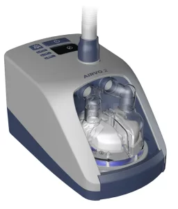
The AIRVO 2 is a humidifier with integrated flow generator that delivers warmed and humidified respiratory gases to spontaneously breathing patients through a variety of patient interfaces.
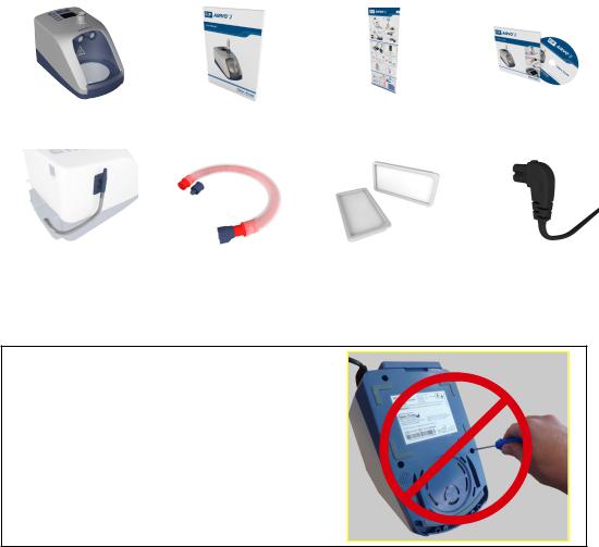
PACKAGE CONTENTS
|
AIRVO 2 humidifier |
AIRVO 2 User Manual |
AIRVO 2 Swingtag |
AIRVO 2 DVD |
|
(PT101xx) |
|
Oxygen inlet extension kit |
Disinfection Kit |
Air filter (x2) |
Power cord |
|
(900PT422) |
(900PT600) |
(900PT913) |
(900PT410xx) |
WARNING
UNDER NO CIRCUMSTANCES SHOULD THE
AIRVO 2 BE OPENED OR ANY OF THE SIX
FASTENING SCREWS ON THE UNDERNEATH
SIDE OF THE DEVICE BE LOOSENED.
OPENING THE UNIT WILL AFFECT THE
OXYGEN SEALS INSTALLED INSIDE, WHICH
WILL COMPROMISE THE SAFETY OF THE
DEVICE.
4
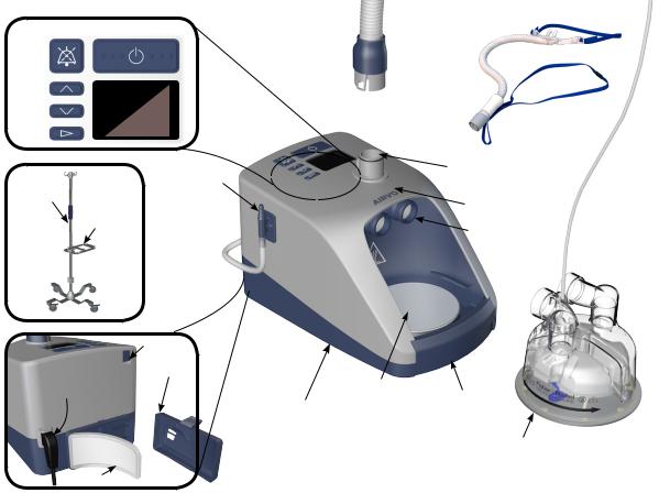
AIRVO 2 AND ACCESSORIES
|
Patient |
||||
|
MUTE ON/OFF (STANDBY) |
interface |
|||
|
Heated |
||||
|
breathing |
||||
|
UP |
tube |
|||
|
DISPLAY |
||||
|
DOWN |
||||
|
MODE |
HEATED BREATHING TUBE |
|||
|
OXYGEN |
CONNECTION PORT |
|||
|
HOSPITAL |
||||
|
INLET PORT |
MEASUREMENT POINT OF |
|||
|
STAND |
||||
|
POLE |
DISPLAYED DEW POINT |
|||
|
MOUNTING |
TEMPERATURE |
TRAY
CHAMBER PORTS
Water chamber
SERIAL PORT
POWER CORD FILTER COVER
|
and |
HEATER |
|
|
CONNECTOR |
||
|
PLATE |
||
AIRVO2
(PT101xx)
AIR FILTER
FINGER
GUARD
AUTO-FILL WATER CHAMBER (MR290) (with adapter fitted)
5
2. SETTING UP AIRVO 2 FOR FIRST USE
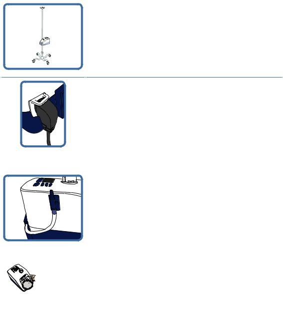
1. REMOVE THE AIRVO 2 FROM ITS PACKAGING
Place the AIRVO 2 on the 900PT405 pole mounting tray, on the 900PT421 hospital stand.
2. CONNECT THE POWER CORD
Plug the power cord connector into the socket on the back of the
AIRVO 2.
3. ATTACH THE OXYGEN INLET EXTENSION KIT
Refer to the instruction sheet included with the kit itself.
4. ATTACH WATER CHAMBER AND HEATED BREATHING TUBE
The water chamber and heated breathing tube must be connected to carry out the following setup and testing procedures.
If you have not been supplied with a reusable HC360 water chamber, you can use an MR290 chamber instead.
6
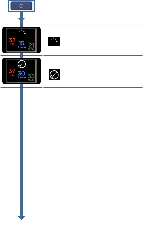
5. SWITCH ON UNIT
Switch on the unit by pressing the On/Off button.
6. WARM-UP
The unit will begin to warm up.
“Warm-up” symbol
7. READY FOR USE
The “Ready for use” symbol means that the system is ready for the patient to use.
“Ready for use” symbol
7

ADVANCED SETTINGS
When you see the “Warm-up” or “Ready for use” symbols, hold a combination of three buttons (Up, Down and Mute) for 5 seconds, to view and change advanced settings.
This button combination is for use by clinical engineering / technical personnel only.
AIRVO 2 / myAIRVO 2 MODE
You can change the unit from “AIRVO” (hospital) mode to “myAIRVO” (home / long-term care) mode, eg. for patients going home.
Contact Fisher & Paykel Healthcare for a myAIRVO 2 User Manual.
To change the mode:
Hold the Up and Down buttons for 3 seconds to “unlock” the setting.
Use the Up button to select myAIRVO 2.
Press the Mode button to confirm the change and/or move on to the next screen. Note that the unit will reset itself if it is switched between AIRVO 2 and myAIRVO 2 modes.
LANGUAGE
You can set the AIRVO 2 / myAIRVO 2 to one of 22 language settings:
|
English |
Nederlands |
Svenska |
Polski |
pl |
العربية |
ar |
|
|
Deutsch |
Português |
[simp.] |
Русский |
ru |
Türkçe |
tr |
|
|
Español |
Dansk |
[trad.] |
עברית |
he |
|||
|
Français |
Suomi |
Ελληνικά |
el |
||||
|
Italiano |
Norsk |
Română |
ro |
To change the language:
Hold the Up and Down buttons for 3 seconds to “unlock” the setting.
Use the Up and Down buttons to select the desired language.
Press the Mode button to confirm the change and/or move on to the next screen.
8
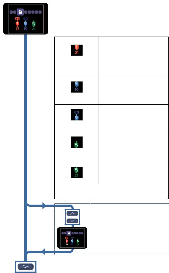
ENVIRONMENT SETTINGS (FOR DEFAULT MODE)
A clinician may change the “Environment Settings”, to customise individual AIRVOs for different environments (eg. intensive care, general care areas, emergency departments). The “Environment Settings”
95chosen will put limits on the “Patient Settings” that the operator can choose when in normal use.
This screen defines the “Environment Settings” for the AIRVO 2 when in Default Mode (ie. non-“Junior Mode”).
|
Minimum dew-point |
The lowest target dew-point temperature that |
|
temperature (°C) |
the operator will be able to select. |
|
Possible Settings: 31, 34, 37 °C |
|
|
If this is set to 31, the operator can select a target |
|
|
dew-point temperature between 31 and 37. ie. 31, |
|
|
34 or 37 (°C). |
|
|
If the patient is tracheostomised, a clinician may |
|
|
wish to set this value to 37, so that the operator |
|
|
can only select a target dew-point temperature |
|
|
between 37 and 37, ie. only 37 (°C). |
|
|
Note: The maximum dew-point temperature |
|
|
setting is always 37 °C in Default Mode. |
|
Minimum flow (L/min) |
The lowest flow that the operator will be able to |
|
select. |
|
|
Possible Settings: 10 to 60 in increments of 5 L/min, |
|
|
always less than or equal to Maximum Flow setting. |
|
|
Example: If this is set to 10, the operator will be |
|
|
able to select flows down to 10 L/min. |
|
|
If this is set to 25, the operator will be able to |
|
|
select flows down to 25 L/min. |
|
Maximum flow (L/min) |
The highest flow that the operator will be able |
|
to select. |
|
|
Possible Settings: 10 to 60 in increments of 5 L/min, |
|
|
always greater than or equal to Minimum Flow setting. |
|
|
Example: If this is set to 60, the operator can |
|
|
select flows up to 60 L/min. |
|
|
If this is set to 35, the operator can select flows up |
|
|
to 35 L/min. |
Maximum oxygen fraction (%) The highest oxygen fraction that the operator
95may set the unit to.
Possible settings: 30 — 100% in increments of 5% O2.
The unit will alarm if the measured oxygen fraction exceeds this value.
Note: Even if this ‘Maximum oxygen fraction‘ setting is set to 100%, any time the measured oxygen fraction exceeds 95%, the oxygen reading will pulse red and the device will beep.
Minimum oxygen fraction (%) The lowest oxygen fraction that the operator may set the unit to.
Possible settings: 21 or 25% O2.
When set to 25% the unit will alarm if the measured oxygen fraction is below this value. This allows detection of oxygen being disconnected.
Note that, for Oxygen display, this is a measurement only, not a control setting. The operator changes the measured oxygen fraction by altering the AIRVO 2 target flow setting and the flow of oxygen connected to the unit (e.g. from a flowmeter) — there is no closed-loop control.
To change the environment settings:
Hold the Up and Down buttons for 3 seconds to “unlock” the first setting.
Use the Up and Down buttons to change the setting,
95then press the Mode button to progress to the next setting.
Press the Mode button to confirm the change and/or move on to the

ENVIRONMENT SETTINGS (FOR JUNIOR MODE)
This screen defines the “Environment Settings” for the AIRVO 2 when in Junior Mode.
|
Junior Mode Enable/Disable |
When this option is enabled (default), the |
|||||
|
95 |
||||||
|
operator can enter Junior Mode from the Home |
||||||
|
Enabled |
Screen, by holding the Mode button for 5 |
|||||
|
seconds. |
||||||
|
When this option is disabled, entering Junior |
||||||
|
Disabled |
mode is not possible. |
|||||
|
Consider disabling this option if the unit will never |
||||||
|
be used on pediatric patients. |
||||||
|
Dew-point |
The only dew-point setting in Junior Mode is |
|||||
|
temperature (°C) |
34 °C. |
|||||
|
Minimum flow (L/min) |
The lowest flow that the operator will be able to |
|||||
|
select. |
||||||
|
Possible Settings: 2 to 25 in increments of 1 L/min, |
||||||
|
always less than or equal to Maximum Flow setting. |
||||||
|
If this is set to 10, the operator will be able to |
||||||
|
select flows down to 10 L/min. |
||||||
|
Maximum flow (L/min) |
The highest flow that the operator will be able |
|||||
|
to select. |
||||||
|
Possible Settings: 2 to 25 in increments of 1 L/min, |
||||||
|
always greater than or equal to Minimum Flow setting. |
||||||
|
If this is set to 15, the operator can select flows up |
||||||
|
to 15 L/min. |
||||||
|
Maximum oxygen fraction (%) |
The highest oxygen fraction that the operator |
|||||
|
may set the unit to. |
||||||
|
95 |
||||||
|
Possible settings: 30 — 100% in increments of 5% O2. |
||||||
|
The unit will alarm if the measured oxygen |
||||||
|
fraction exceeds this value. |
||||||
|
Note: Even if this ‘Maximum oxygen fraction‘ |
||||||
|
setting is set to 100%, any time the measured |
||||||
|
oxygen fraction exceeds 95%, the oxygen reading |
||||||
|
will pulse red and the device will beep. |
||||||
|
Minimum oxygen fraction (%) |
The lowest oxygen fraction that the operator |
|||||
|
may set the unit to. |
||||||
|
Possible settings: 21 or 25% O2. |
||||||
|
When set to 25% the unit will alarm if the |
||||||
|
measured oxygen fraction is below this value. This |
||||||
|
allows detection of oxygen being disconnected. |
||||||
|
Note that, for Oxygen display, this is a measurement only, not a control setting. The |
||||||
|
operator changes the measured oxygen fraction by altering the AIRVO 2 target |
||||||
|
flow setting and the flow of oxygen connected to the unit (e.g. from a flowmeter) |
||||||
|
— there is no closed-loop control. |
||||||
To change the environment settings:
Hold the Up and Down buttons for 3 seconds to “unlock” the first setting.
Use the Up and Down buttons to change the setting, then press the Mode button to progress to the next setting.
Press the Mode button to confirm the change and/or move on to the next screen..
10
 Loading…
You can only view or download manuals with
Sign Up and get 5 for free
Upload your files to the site. You get 1 for each file you add
Get 1 for every time someone downloads your manual
Buy as many as you need
Высокопоточная назальная терапия Optiflow™ осуществляемая аппаратом Airvo 2
Система для увлажненной высокопоточной назальной терапии и подачи высокопоточной терапии к трахеостаме
![]()
Краткое описание аппарата AIRVO 2
Airvo 2 — это система для увлажненной высокоточной назальной терапии, разработанная для лечения пациентов на всех этапах оказания помощи.
-
Благодаря эффективности широкого диапазона скоростей потока (2–60 л/мин) система поможет вашим пациентам выписаться из отделений ОРИТ и скорой помощи и отправиться домой.
-
Система со встроенным генератором потока подразумевает портативность – нет необходимости в шумном, тяжелом компрессоре или централизованной подаче воздуха.
-
Разнообразие интерфейсов, разработанных специально для проведения высокопоточной назальной терапии Optiflow. При высоких скоростях потока необходимо добиться высокого уровня комфорта, что и призван обеспечить интерфейс.
Введение
(5,05 мин)
В 1-й части видеоинструкции к аппарату AIRVO 2 приводится его описание, принцип работы, а также обоснования использования активного увлажнителя с подогревом, за счет которого обеспечивается уровень оптимальной влажности.
Настройка
(3,37 мин)
2-я часть видеоинструкции к аппарату AIRVO 2 представляет собой пошаговое руководство по настройке аппарата AIRVO 2 и знакомство с набором интерфейсов.
Эксплуатация
(6,03 мин)
В 3-й части видеоинструкции к аппарату AIRVO 2 приводится руководство пользователя аппаратом AIRVO 2, в том числе описана регулировка основных настроек, например потока или температуры, а также порядок подключения дополнительного кислорода (при необходимости).
Повторная обработка
(5,25 мин)
В 4-й части видеоинструкции к аппарату AIRVO 2 приводится инструкция по очистке и дезинфекции аппарата AIRVO 2; повторная обработка и интенсивная дезинфекция аппарата для использования его у следующего пациента.
Краткое описание функций

Разнообразие интерфейсов Optiflow
Систему Airvo 2 можно использовать как с назальной канюлей Optiflow, так и с масочным или трахеостомическим интерфейсом.

Контролируемая доставка кислорода (при необходимости)
Кислород можно подключить от концентратора или баллона. Встроенному ультразвуковому анализатору кислорода не требуется калибровка, обслуживание или замена.

Конструкция, облегчающая настройку, использование и очистку
Анимированные подсказки на экране помогают в настройке и устранении неисправностей.

Регулируемые настройки температуры и потока
Три уровня настройки температуры: 37, 34 и 31 °С. Интегрированный генератор потока обеспечивает скорость потока 2–60 л/мин. Подключения к центральной системе подачи воздуха не требуется.
Ресурсы поддержки
Airvo 2
Руководство пользователя/инструкции Airvo 2
English, Česky, Polski, Русский, Türkçe, Ελληνικά, Română, Hrvatski, Slovenščina, Slovenský, Magyar, עברית ارسی, Български, Eesti, Latviski, Lietuvių k.
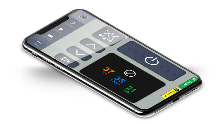
Приложение AIRVO 2
в вашем кармане
Загрузите приложение-тренажер AIRVO 2 и держите этот замечательный обучающий инструмент под рукой. Используйте приложение, чтобы:
• научиться применению системы AIRVO 2
• быстро и легко научить других применению системы AIRVO 2
• проверить свои навыки
Загрузите приложение-тренажер AIRVO 2 бесплатно прямо сейчас.


Specifications:1436/1436352-airvo_2.pdf file (17 May 2023) |
Accompanying Data:
FP AIRVO 2 Medical Equipment PDF Operation & User’s Manual (Updated: Wednesday 17th of May 2023 12:04:53 AM)
Rating: 4.6 (rated by 9 users)
Compatible devices: MEDCAPTAIN NAVI-30, Eson 2, hydrocollator, SleepStyle Auto, Plié3 MPC Knee, Nivairo RT047 XS, Varios 560 LUX, ICON Auto.
Recommended Documentation:
Operation & User’s Manual (Text Version):
(Ocr-Read Summary of Contents of some pages of the FP AIRVO 2 Document (Main Content), UPD: 17 May 2023)
-
2, A – 1 English BEFORE YOU START • This User Manual is intended for healthcare professionals. • This User Manual applies to AIRVO 2 units with LOT numbers 130621 and above. • Read this User Manual including all warnings. Failure to do so may result in injury. In addition, watch the AIRVO 2 Video Guide. Keep them both in a safe place for future reference. • Before the AIRVO 2 is used for the first time, it must be set up according to the instructions in the AIRVO 2 Technical Manual. • The AIRVO 2 must be…
-
3, A – 2 1. OVERVIEW The AIRVO 2 is a humidifier with integrated flow generator that delivers high flow warmed and humidified respiratory gases to spontaneously breathing patients through a variety of patient interfaces. INTENDED USE The AIRVO 2 is for the treatment of spontaneously breathing patients who would benefit from receiving high flow warmed and humidified respiratory gases. This includes patients who have had upper airways bypasse…
-
4, A – 3 English AIRVO 2 AND ACCESSORIES OXYGEN INLET PORT HEATER PLATE FINGER GUARD AUTO-FILL WATER CHAMBER (MR290) (with adapter fitted) Heated breathing tube Water chamber Patient interface HOSPITAL STAND POLE MOUNTING TRAY Cleaning and Disinfection 900PT600 Disinfection Kit 900PT601 Disinfection Filter (2-Pack) 900PT602 Cleaning Sponge-Stick (20-Pack) 900PT603 Clean Storage Cover (20-Pack) Miscellaneous 900PT405 Pole mounting tray 900PT421 Hospital stand 900PT422 Oxygen inlet extension kit …
-
5, FP AIRVO 2 A – 4 2. SETTING UP AIRVO 2 1. BEFORE YOU BEGIN The AIRVO 2 should be fixed on a pole mounting tray (900PT405) below patient head height. Open the packaging of the tube & chamber kit (heated breathing tube, MR290 auto-fill chamber and adapter). 2. INSTALL WATER CHAMBER Remove the blue port caps from the chamber by pulling the tear tab upwards then remove the bracket holding the water supply tube. Fit the supplied adapter over the two vertical ports on the chamber and push on fully then clip the water supply tube into positio…
-
6, A – 5 English 4. INSTALL HEATED BREATHING TUBE One end of the heated breathing tube has a blue plastic sleeve. Lift the sleeve and slide the connector onto the unit. Push the sleeve down to lock. WARNINGS To avoid burns: • Do not modify the breathing tube or interface in any way. • Do not allow the breathing tube to remain in direct contact with skin for prolonged periods of time. • Adding heat, above ambient levels, to any part of the breathing tube …
-
7, FP AIRVO 2 A – 6 3. USING AIRVO 2 1. SWITCH ON UNIT Plug the unit’s power cord into the mains power supply. The connector at the other end of the power cord should be well secured to the rear of the unit. WARNINGS To avoid electric shock: • Ensure that the unit is dry before plugging into the power socket. Switch on the unit by pressing the On/O button. Last Disinfection: #16 2. CHECK DISINFECTION STATUS The unit will show you whether it is safe for use on a new patient. This AIRVO 2 is safe for use on a new patient. This AIRVO 2 has not bee…
-
8, A – 7 English 5. CONFIGURE TARGET SETTINGS Press the Mode button to view target settings. These settings are locked by default. TARGET DEW-POINT TEMPERATURE You can set the AIRVO 2 to three target dew-point temperature settings: • 37°C (98.6°F) • 34°C (93°F) [if compliance at 37°C is a problem] • 31°C (88°F) [for face masks only]. You may not have access to all settings, if: • the unit is in Jun…
-
9, A – 8 Press the Mode button to move on to the next screen. OXYGEN You can connect supplementary oxygen to the AIRVO 2 (up to 60 L/min). The AIRVO 2 contains an oxygen analyzer to help you determine the oxygen fraction you are delivering to the patient. Your unit may have been initially set up with tighter limits. Use continuous oxygen monitoring on patients who would desaturate significantly in the event of disruption to their oxygen supply. WARNINGS Before using t…
-
10, A – 9 English 6. CONNECT YOUR PATIENT Wait until the “Ready for use” symbol is displayed on the Summary screen. “Ready for use” symbol Connect the patient interface to the heated breathing tube. Monitor the flow and oxygen values displayed on the Summary screen. Adjust the level of oxygen from the oxygen source as necessary. When the patient first uses the unit, the air will feel warm. This is normal. The patient should continue to breathe normally through the nose and/or mouth, or …
-
11, FP AIRVO 2 A – 10 ALARMS The AIRVO 2 has visual and auditory alarms to warn you about interruptions to your patient’s treatment. These alarms are generated by an intelligent alarm system, which processes information from the sensors and target settings of the unit and compares this information to pre-programmed limits. ALARM SIGNALS Symbols Meaning Visual alarm signal (message) Alarm condition. Audio paused. Auditory alarm signal 3 beeps in…
-
12, FP AIRVO 2 A – 11 English (continued) Message Meaning Aects delivery of: Delays Cannot reach target flow The unit cannot reach the target flow setting. Check the heated breathing tube or patient interface for blockage. Check whether the target flow setting is too high for the patient interface being used (refer to “Setting up AIRVO 2” — ”Select Patient Interface”). The unit will choose appropriate new target settings. You will be prompted for acknowledgement. WARNINGS • The oxygen concentration delivered …
-
13, A – 12 4. REPROCESSING The AIRVO 2 must be cleaned and disinfected between patients according to the instructions in the Disinfection Kit Manual (900PT600). This should take place as soon as possible after use. The unit utilizes warmed water and can pose a risk of bacterial colonization and patient infection if cleaning, disinfection and replacement procedures are not followed. Standard aseptic techniques to minimize contamination should be followed when handling the unit and accessories. This includes…
-
14, FP AIRVO 2 A – 13 English 5. TECHNICAL INFORMATION SYMBOL DEFINITIONS Caution Hot Surfaces Type BF Applied Part ATTENTION Consult accompanying documents Do not throw away Drip Proof Alternating Current Class ll Double Insulated Power On/Off (Standby) 93/42/EEC Class IIa PRODUCT SPECIFICATIONS Dimensions 295 mm x 170 mm x 175 mm (11.6” x 6.7” x 6.9”) Weight 2.2 kg (4.8 lb) unit only, 3.4 kg (7.5 lb) packaged in bag incl. accessories Supply frequency 50-60 Hz Supply voltage/current 100-115 V 2.2 A (2.4 A max) 220-240 V 1.8 A (2.…
-
15, REF 185048127 REV A 2013-June © 2013 Fisher & Paykel Healthcare Limited 0123 Australia Fisher & Paykel Healthcare Pty Limited 36-40 New Street, PO Box 167 Ringwood, Melbourne Victoria 3134, Australia Tel: +61 3 9879 5022 Fax: +61 3 9879 5232 Austria Tel: 0800 29 31 23 Fax: 0800 29 31 22 Benelux Tel: +31 40 216 3555 Fax: +31 40 216 3554 China Tel: +86 20 3205 3486 Fax: +86 20 3205 2132 France Tel: +33 1 6446 5201 Fax: +33 1 6446 5221 Germany Tel: +49 7181 98599 0 Fax: +49 7181 98599 66 India Tel: +91 80 4284 4000…
-
FP AIRVO 2 User Manual
-
FP AIRVO 2 User Guide
-
FP AIRVO 2 PDF Manual
-
FP AIRVO 2 Owner’s Manuals
Recommended:
408, GDR-H30N, ADDRESSRIGHT DA300
-
LiNA Gold LoopTMInnovation in GynecologyLiNA is a registered trademark of LiNA Medical in EU, US and CN2017-12 FV0023NLiNA Medical ApS — Formervangen 5 — DK-2600 Glostrup — DENMARK — Tel: +45 4329 6666 — Fax: +45 4329 6699 — e-mail: [email protected] — www.lina-medical.com …
Gold Loop EL-160-8 15
-
Instructions for cleaning and sterilization Lensmeter VX40This instruction guide aims to clean and sterilize your VX40 for common use .For other instructions, please refer to the USER MANUAL. For your comfort it’s recommended to clean the device regularly. Please clean the instrument following these instructions. Cleaning conducted by a process other than the one described in this ins …
VX40 2
-
Controls & DisplayII. Headphone and Audio ConnectionMinus KeyDiaphragmFilter Key Alt KeyPlus Keyfa+100Hz0faHz ScaleFilter Setting0-10 ScaleVolume Batt LevelBattery LEDVolume LEDThinklabs OneDigital StethoscopeQuick Reference GuideCongratulations. You now own a state of the art auscultation instrument made with advanced technology and fine materials. Thinklabs One is design …
One 2
-
12345710981161234571098116EN Instructions for Use PT Instruções de uso RU Инструкция по пользованию PL Instrukcja obsługi HR Uputa za uporabu EL Οδηγίες χρήσης CS Návod k použití SK Návod na použitie DA Brugsanvisning NO Bruksanvisning SV Bruksanvisning FI Käyttöohje MK Патство за употреба Löwenstein Medical T …
JOYCEone 28
-
MES-CK08-068-21EN Prepared: 2020-05-14 (Ver.2) Shoulder Positioner Operator’s Manual Table of Contents 1. Introduction …………………………………… 22. Component …………………………………… 33. Instructions for use ………………………… 44. Maintenance / Inspection ……………….. 55. Specific …
5348 8
-
Figure 1 — Model M66119 30st190kg25st160kg4.1 M66119 Only Fit the adjustable height castors to the main chassis by sliding the tube inside the chassis frame, to the desired height and secure using an ‘e-clip’. Please Note: the height should be set such that the user feels comfortable but also allows for adequate clearance if being used over a toilet. Always ensure all four castors a …
L22056 2
Popular Right Now:
Operating Impressions, Questions and Answers:
Similar Devices: DePuy Synthes Electric Pen Drive, 4SPORT, MiniMed 640G
-
Please keep and refer to this Owner’s Manual.Owner’s Manual1-800-634-7328 DirectSupply.comPanacea®MOTIONTURN MATTRESS & MOTIONTURN BARIATRICMATTRESS Thank you for purchasing a Panacea® MotionTurn Mattress from Direct Supply Equipment & Furnishings®. Please read this entire guide carefully and keep it for future reference. This guide will prov …
Panacea, 20
-
Visit nonin.com for more information and video tutorials.quick guideNonin Medical, Inc. 13700 1st Avenue North Plymouth, MN 55441-5443 • USA Tel: +1.763.553.9968 +1.800.356.8874 Fax: +1.763.577.5521 E-mail: [email protected] Medical B.V.Prins Hendriklaan 26 1075 BD Amsterdam • Netherlands Tel: +31 (0)13 — 79 99 040 Fax: +31 (0)13 — 79 99 0 …
Avant 9600, 2
-
FAULT FINDINGShould your Arctic bed fail to function, please check the following.1. Check the Charger is plugged into a 13amp socket2. Check to see if any of the following lights are showing on the charger.Red — ChargingAmber- Charged Green — Fully Charges3. Check the connections of handset to the bed, the handset can be fittedto either the left or right han …
ARCTIC, 2
-
Kegel8® Mother Nurture Operation Manual56Savantini Ltd.Savantini House, Foster StreetStoneferry RoadHull, HU8 8BTEnglandAny queries should be addressed to:Helpline +44(0)1482 496 932Call us! We’re here to help you Monday-Friday, 8am — 5pm.Distributor:Not for sale or use in the USAAccessory control information:Kegel8Mother Nurture manual(English)OPH3 …
Mother Nurture, 28
-
PLATINUM 5OXYGEN CONCENTRATORS STANDARD,WITH/SENSO2® AND HOMEFILL IICONCENTRADORES DE OXÍGENOSTANDARD, CON/SENSO2®Y HOMEFILL IIOPERATOR’S MANUAL — ENGLISHMANUAL DE INSTRUCCIONES -DOMESTIC SPANISHDEALER: THIS MANUAL MUST BE GIVEN TO THE END USER.USER: BEFORE USING THIS CONCENTRATOR, READTHIS MANUAL AND SAVE FOR FUTURE REFERENCE.DISTRIBUIDOR: ENT …
IRC5LX, 44
-
©2020 IFU-0100 / rev3 INSTRUCTION FOR USE SPY-PHI Articulating Arm HH1001 Main Arm / HH1002 Table Clamp / HH1003 Imaging Head Holder EN | FR | DE | IT | PT | PT-BR | ES | NL | CZ | DA | FI | NO | SV | PL | EL | TR | RU | JA | KO | ZH-CN | ZH-TW| RO …
SPY-PHI Articulating Arm, 256
-
Redefining patient handlingOxford®/Hoyer® ElevateUser Instruction Manual & WarrantyTo avoid injury, read user manual prior to use.Oxford®/Hoyer® ElevateManuel de l’utilisateur et garantieAfin d’éviter tout accident, veuillez lire attentivement la notice avant utilisation.Oxford®/Hoyer® ElevateManual de Instrucciones y Garantia para el Usuario …
Oxford, 28
![]()
![]() User Manual
User Manual
BEFORE YOU START
- This User Manual is intended for healthcare professionals.
- This User Manual applies to AIRVO 2 units with LOT numbers 130621 and above.
- Read this User Manual including all warnings. Failure to do so may result in injury. In addition, watch the AIRVO 2 Video Guide. Keep them both in a safe place for future reference.
- Before the AIRVO 2 is used for the first time, it must be set up according to the instructions in the AIRVO 2 Technical Manual.
- The AIRVO 2 must be cleaned and disinfected between patients according to the instructions in the
Disinfection Kit Manual (900PT600). - For further assistance, please contact your Fisher & Paykel Healthcare representative.
OVERVIEW
The AIRVO 2 is a humidifier with an integrated flow generator that delivers high flow warmed and humidified respiratory gases to spontaneously breathing patients through a variety of patient interfaces.
INTENDED USE
The AIRVO 2 is for the treatment of spontaneously breathing patients who would benefit from receiving high-flow warmed and humidified respiratory gases. This includes patients who have had upper airways bypassed. The flow may be from 2 – 60L/min depending on the patient interface. The AIRVO 2 is for patients in hospitals and long-term care facilities.
USA Federal Law restricts this unit for sale by or on the order of a physician.
![]() WARNINGS
WARNINGS
- Nasal delivery of respiratory gases generates flow-dependent positive airway pressure (PAP). This must be taken into account where PAP could have adverse effects on a atient.
- The unit is not intended for life support.
To avoid burns: - The unit should only be used with interfaces, water chambers, and breathing tubes specified in this user manual.
- Using the breathing tube or interface for longer than the specified time can result in serious injury including infection.
- Before using oxygen with the unit, read all warnings in the “Oxygen” section of this manual.
- Never operate the unit if:
• the heated breathing tube has been damaged with holes, tears, or kinks,
• it is not working properly,
• the case screws have ever been loosened. - Do not block the flow of the air through the unit and breathing tube.
- The unit should be located in a position where ventilation around the unit is not restricted.
- Never block the air openings of the unit or place it on a soft surface such as a bed or couch/sofa, where the filter area may be blocked. Keep the air openings free of lint, hair, etc.
To avoid electric shock: - Do not store or use the unit where it can fall or be pulled into the water. If water has entered the unit enclosure, disconnect the power cord and discontinue use.
- Never operate the unit if:
• it has been dropped or damaged,
• it has a damaged power cord or plug,
• it has been dropped into water. - Avoid unnecessary removal of the power cord from the rear of the device. If removal is necessary, hold the connector during removal. Avoid pulling on the power cord.
- Return the unit to an authorized service center for examination and repair, except as outlined in this manual.
To avoid choking or inhalation of a foreign object: - Ensure an air filter is fitted when operating your unit.
- Never drop or insert any object into any opening or tube.
Miscellaneous: - Do not use the unit when the room temperature exceeds 30°C (86°F) or is below 10°C (50°F) as the unit may switch off. Humidity output will be compromised below 18°C (64°F) and above 28°C (82°F).
- The unit is not suitable for use in the presence of a flammable, anesthetic mixture with air or oxygen or nitrous oxide.
AIRVO 2 AND ACCESSORIES
Tube and chamber kits and patient interfaces
| Tube & chamber kit | Interfaces | ||
| 900PT531 | Heated breathing tube, MR290 auto-fill chamber, and adapter (10-Pack) | OPT316 OPT318 |
Nasal Cannula – Infant (20-Pack) Nasal Cannula – Pediatric (20-Pack) |
| 900PT501 | Heated breathing tube, MR290 auto-fill chamber, and adapter (10-Pack) | OPT842 OPT844 OPT846 OPT870 RT013 |
Nasal Cannula – Small (20-Pack) Nasal Cannula – Medium (20-Pack) Nasal Cannula – Large (20-Pack) Tracheostomy Direct Connection (20-Pack) Mask Interface Adapter – 22mm (20-Pack) |
Cleaning and Disinfection
| 900PT600 | Disinfection Kit |
| 900PT601 | Disinfection Filter (2-Pack) |
| 900PT602 | Cleaning Sponge-Stick (20-Pack) |
| 900PT603 | Clean Storage Cover (20-Pack) |
Miscellaneous
| 900PT405 | Pole mounting tray |
| 900PT421 | Hospital stand |
| 900PT422 | Oxygen inlet extension kit |
| 900PT912 | Filter holder |
| 900PT913 | Air filter (2-Pack) |
| OPT012 | Wigglepads (OPT316/OPT318) (20-pack) |
| OPT014 | Oxygen Tubing (Optiflow Junior) |
SETTING UP ARVO 2
BEFORE YOU BEGIN
The AIRVO 2 should be fixed on a pole mounting tray (900PT405) below the patient head height.
Open the packaging of the tube & chamber kit (heated breathing tube, MR290 auto-fill chamber, and adapter).
INSTALL WATER CHAMBER
Remove the blue port caps from the chamber by pulling the tear tab upwards then remove the bracket holding the water supply tube.
Fit the supplied adapter over the two vertical ports on the chamber and push on fully then clip the water supply tube into position.
Fit the water chamber to the unit by pressing down the finger guard and sliding the chamber on, carefully aligning with the blue chamber portends.
Push the chamber on firmly until the finger guard clicks into place.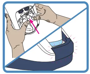
![]() WARNINGS
WARNINGS
To avoid burns:
- Do not start the unit without the water chamber in place.
- The water in the chamber becomes hot during use. Exercise caution when removing and emptying the chamber.
- Do not touch the heater plate, water chamber, or chamber base during use.
To avoid electric shock: - When handling the unit with the water chamber in place, avoid tilting the machine to prevent any chance of water entering the unit enclosure.
- Empty all the water from the water chamber before transporting the unit.
CAUTIONS
To ensure optimal therapy (MR290 only): - Do not use the auto-fill MR290 chamber if it has been dropped or been run dry
and the “water out” alarm has been activated.
CONNECT WATER BAG
Attach the sterile water bag to the hanging bracket 20cm (8”) above the unit, and push the bag spike into the fitting at the bottom of the bag.
Open the vent cap on the side of the bag spike. The chamber will now automatically fill to the required level and maintain that level until the water bag is empty.
To ensure continual humidification, always ensure that the water chamber and/or water bag are not allowed to run out of water.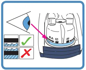
Check that water flows into the chamber and is maintained below the fill line. If the water level rises above the fill line, replace the chamber immediately.
MR290: Flow setting vs usage time (2-liter sterile water bag)
| L/min | 2 | 5 | 10 | 15 | 20 | 25 | 30 | 35 | 40 | 45 | 50 | 55 | 60 |
| hrs | 379 | 152 | 76 | 51 | 38 | 30 | 25 | 22 | 19 | 17 | 15 | 14 | 13 |
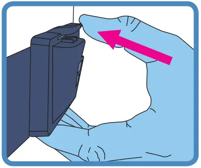
INSTALL HEATED BREATHING TUBE
One end of the heated breathing tube has a blue plastic sleeve. Lift the sleeve and slide the connector onto the unit. Push the sleeve down to lock.
![]() WARNINGS
WARNINGS
To avoid burns:
- Do not modify the breathing tube or interface in any way.
- Do not allow the breathing tube to remain in direct contact with the skin for prolonged periods of time.
- Adding heat, above ambient levels, to any part of the breathing tube or interface e.g. covering with a blanket, or heating it in an incubator or overhead heater for a neonate, could result in serious injury.
- Do not use an insulating sleeve or any similar accessories which are not recommended by Fisher & Paykel Healthcare.
CAUTIONS - Position the heated breathing tube away from any electrical monitoring leads (EEG, ECG/EKG, EMG, etc), to minimize any possible interference with the monitored signal.
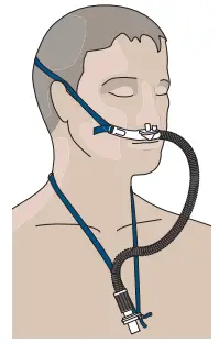
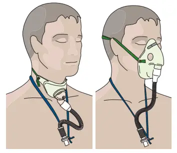
SELECT PATIENT INTERFACE
The AIRVO 2 can be used with a variety of patient interfaces. Read the separate user instructions for the patient interface that will be used, including all warnings.
| Nasal cannula | Tracheostomy interface | Mask interface adapter | |
 |
 |
 |
 |
| OPT842 OPT844 OPT846 |
VO AIR OPT316, OPT318 (Refer to “Using AIRVO 2” – ”Junior Mode”) | OPT870 | RT013 (with mask) Note that the RT013 Mask Interface Adapter is designed to be used with ented masks only. Do not use sealed masks. |
The following table shows the target dew-point temperature settings and target flow settings able to be used with these interfaces.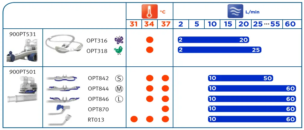
Low-temperature ambient conditions may prevent the unit from reaching a 37 °C target temperature setting at high target flow settings. In these cases, consider decreasing the target flow setting.
WARNINGS
To avoid burns:
- Do not modify the breathing tube or interface in any way.
- Do not use any patient interfaces not listed here.
USING AIRVO 2
SWITCH ON UNIT
Plug the unit’s power cord into the main power supply. The connector at the other end of the power cord should be well secured to the rear of the unit.
WARNINGS
To avoid electric shock:
- Ensure that the unit is dry before plugging into the power socket. Switch on the unit by pressing the On/Off button.
CHECK DISINFECTION STATUS
The unit will show you whether it is safe for use on a new patient.
WARM-UP
The unit will begin to warm up. You will see numbers showing the current output dew-point temperature, flow and oxygen values. These numbers will pulse until they approach their target settings. This screen is called the “Summary screen”.
JUNIOR MODE
If the patient will be using an Optiflow Junior nasal cannula (OPT316/ OPT318), you must activate Junior Mode.
Junior Mode limits the target settings to 34 °C and 2 – 25 L/min, in increments of 1 L/min.
To activate Junior Mode:
 |
Hold the Mode button for 5 seconds. |
| New target settings The target settings for dew-point temperature and flow will be changed automatically. The colorful icons in the corners of the screen indicate that this unit is in Junior Mode. |
|
| To deactivate Junior Mode, follow the same procedure: hold the Mode button for 5 seconds. |
CONFIGURE TARGET SETTINGS
Press the Mode button to view target settings.
![]() These settings are locked by default.
These settings are locked by default.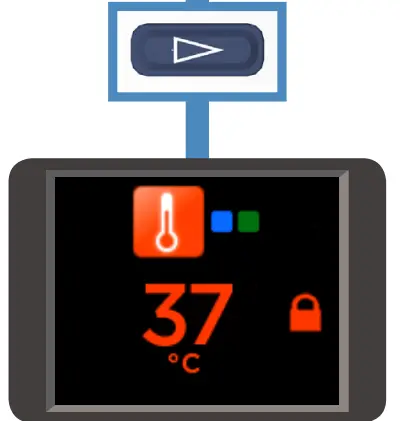
TARGET DEW-POINT TEMPERATURE
You can set the AIRVO 2 to three target dew-point temperature settings:
- 37°C (98.6°F)
- 34°C (93°F) [if compliance at 37°C is a problem]
- 31°C (88°F) [for face masks only].
You may not have access to all settings, if: - the unit is in Junior Mode (limited to 34 °C),
- the unit was initially set up with tighter limits.
The AIRVO 2 will return to its default setting (37°C) after every disinfection cycle.
To change the target dew-point temperature setting:
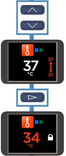 |
Hold the Up and Down buttons for 3 seconds to “unlock” the setting. |
| The lock will disappear and be replaced by an arrow showing the minimum and maximum accessible settings. Press the Up and Down buttons to choose the new setting. | |
| When you have finished, press the Mode button to ‘lock’ the setting again. | |
| The lock will reappear. |
Transport Mode:
![]() If Transport Mode has been enabled, you can activate it on this screen by holding the ”Audio pause” button for 5 seconds. The unit will enter a low-power, low-humidity mode for 20 minutes, designed for use when transporting patients.
If Transport Mode has been enabled, you can activate it on this screen by holding the ”Audio pause” button for 5 seconds. The unit will enter a low-power, low-humidity mode for 20 minutes, designed for use when transporting patients.
For more information, refer to REF 185048130.
To deactivate Transport Mode, follow the same procedure: hold the “Audio pause” button for 5 seconds.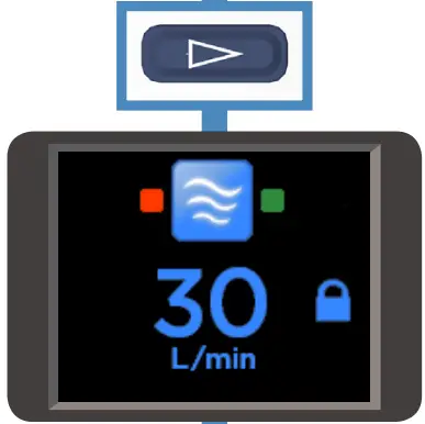
Press the Mode button to move on to the next screen.
TARGET FLOW
You can set the AIRVO 2 to flows between 10 L/min and 60 L/min, in increments of 1 L/min (10-25 L/min) and 5 L/min (25-60 L/min).
You may not have access to all settings, if:
- the unit is in Junior Mode (limited to 2 – 25 L/min, in increments of 1 L/min),
- the unit was initially set up with tighter limits.
The AIRVO 2 will remember its target flow setting when you switch it off.
To change the target flow setting:
Follow the same sequence of steps as above in “To change the target dew-point temperature setting”.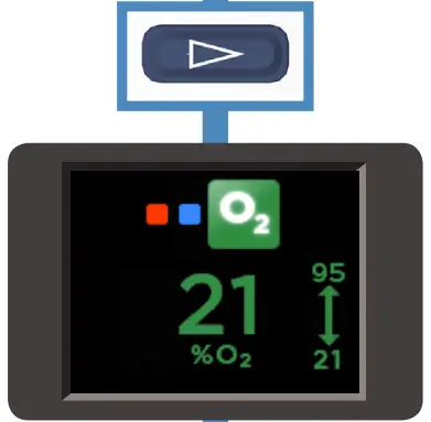
Press the Mode button to move on to the next screen.
OXYGEN
You can connect supplementary oxygen to the AIRVO 2 (up to 60 L/min). The AIRVO 2 contains an oxygen analyzer to help you determine the oxygen fraction you are delivering to the patient. Your unit may have been initially set up with tighter limits.
Use continuous oxygen monitoring on patients who would desaturate significantly in the event of a disruption to their oxygen supply.
![]() WARNINGS
WARNINGS
Before using the AIRVO 2 with oxygen, read all of the following warnings:
- The use of oxygen requires that special care be taken to reduce the risk of fire. Accordingly, for safety, it is necessary that all sources of ignition be kept away from the unit and preferably out of the room in which it is being used. Oxygen should not be used while smoking or in the presence of an open flame. The unit should be located in a position where ventilation around the unit is not restricted.
- A spontaneous and violent ignition may occur if oil, grease, or greasy substances come in contact with oxygen under pressure. These substances must be kept away from all oxygen equipment.
- Ensure that the AIRVO 2 is switched on before connecting oxygen.
- Oxygen must only be added through the special oxygen inlet port on the back of the unit. To ensure that oxygen enters the unit correctly, the oxygen inlet port must be fitted properly to the filter holder and the filter holder must be fitted properly to the unit. The power cord connector should also be well secured.
- Do not connect more than 60L/min O2 to the oxygen inlet port on the back of the unit.
- The oxygen concentration delivered to the patient can be affected by changes to the flow setting, oxygen setting, patient interface, or if the airpath is obstructed.
- When finished, turn off the oxygen source. Remove the output of the oxygen source from the oxygen inlet port on the back of the unit. The oxygen flow must be turned off when the unit is not operating so that oxygen does not build up inside the device.
- The oxygen analyzer within the AIRVO 2 uses ultrasonic measurement technology. It does not require in-field calibration. It is designed for use with pure oxygen – connecting any other gases or mixtures of gases will cause it to function incorrectly.
CONNECT OXYGEN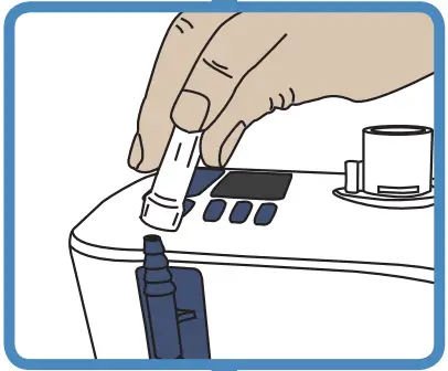
Connect the output from the oxygen source to the oxygen inlet port on the back of the unit. Make sure you push the oxygen tube firmly onto this connection port.
ADJUST OXYGEN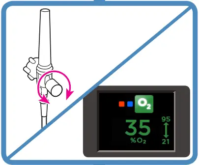
Adjust the level of oxygen from the oxygen source, until the desired oxygen fraction is displayed onscreen. It may take the reading several minutes to settle. You can set the oxygen fraction between the maximum and minimum values displayed above and below the arrow.
If the oxygen fraction exceeds 95%, the oxygen reading will pulse red and the device will beep.
WARNINGS
- Note that if the patient’s peak inspiratory demand exceeds the flow delivered by the unit, the fraction of oxygen inspired by the patient will be lower than the value shown onscreen, due to the additional entrainment of ambient air.
- Check that suitable blood saturation levels are achieved at the prescribed flow.
![]()
Press the Mode button to return to the Summary screen.
6. CONNECT YOUR PATIENT
Wait until the “Ready for use” symbol is displayed on the Summary screen.
![]() The “Ready for use” symbol
The “Ready for use” symbol
Connect the patient interface to the heated breathing tube.
Monitor the flow and oxygen values displayed on the Summary screen.
Adjust the level of oxygen from the oxygen source as necessary.
When the patient first uses the unit, the air will feel warm. This is normal. The patient should continue to breathe normally through the nose and/or mouth, or tracheostomy.
DURING USE
If the “Ready for use” symbol has been displayed for 1 minute and no button has been pushed in this time, a screensaver will be launched.
If excess condensate accumulates in the heated breathing tube, drain by lifting the patient end of the tube, allowing the condensate to run into the water chamber.
AFTER USE
Switch off the unit by pressing the On/Off button.
ALARMS
The AIRVO 2 has visual and auditory alarms to warn you about interruptions to your patient’s treatment.
These alarms are generated by an intelligent alarm system, which processes information from the sensors and target settings of the unit and compares this information to pre-programmed limits.
ALARM SIGNALS
| Symbols | Meaning | |
| Visual alarm signal | ||
 |
Alarm condition. | |
| Audio paused. |
Auditory alarm signal
| 3 beeps in 3 seconds. Repeated every 5 seconds. |
Press this button to mute the auditory alarm for 115 seconds. The auditory alarm can be reactivated by pressing this button again. |
ALARM CONDITIONS
All of the alarms listed below have been assessed as “Medium Priority”. These priorities have been allocated for an operator’s position within 1 meter of the device. The unit also uses an internal priority ranking system. If multiple alarm conditions occur simultaneously, the unit will display the highest-priority alarm.
The following table lists all of the alarm conditions from highest-priority to lowest priority, their causes, possible solutions, and delays. Alarm conditions that affect oxygen delivery require an immediate response to assess the patient’s saturation levels. Alarm conditions that affect humidity delivery require a prompt response to assess the potential drying of mucus and associated blockages.
| Message | Meaning | Affects delivery of: | Delays |
| Fault (E###) | ‘The unit has detected an internal fault and has shut itself down. Switch the unit off and then restart. If the problem persists, note the fault code and contact your Fisher & Paykel Healthcare representative. |
Oxygen, humidity. | < 5 seconds |
| Check tube | The unit cannot detect the heated breathing tube. Check that the heated breathing tube is not damaged and that it is plugged incorrectly. If the problem persists, then change the heated breathing tube. |
Oxygen, humidity. | < 5 seconds |
| Check for leaks | The unit has detected a leak in the system. The most likely cause is that the water chamber has been removed or has not been pushed into place correctly. Check that the heated breathing tube is not damaged and that it is plugged incorrectly. Check that the nasal interface is fitted. Check that the filter is fitted. |
Oxygen, humidity. | < 5 seconds |
| Check for blockages | The unit has detected a blockage in the system. Check the heated breathing tube or patient interface for blockage. Check the air filter and filter holder for blockage. Check whether the unit should be in Junior Mode. If the patient will be using an Optiflow Junior nasal cannula (OPT316/OPT318), you must activate Junior Mode. |
Oxygen, humidity. | <10 seconds |
| 02 too low | The measured oxygen level has fallen below the allowed limit. Check that the oxygen source is still correctly connected. Adjust the level of oxygen from the oxygen source as necessary. | Oxygen | < 20 seconds |
| 02 too high | The measured oxygen level has exceeded the allowed limit. _ Adjust the level of oxygen from the oxygen source as necessary. |
Oxygen | < 20 seconds |
| Message (continued) | Meaning | Affects delivery of: | Delays |
| Cannot reach target flow | The unit cannot reach the target flow setting. Check the heated breathing tube or patient interface for blockage. Check whether the target flow setting is too high for the patient interface being used (refer to “Setting up AIRVO 2” – ”Select Patient Interface”). The unit will choose appropriate new target settings. You will be prompted for acknowledgment. • The oxygen concentration delivered to the patient can be affected by changes to the flow setting. Adjust the level of oxygen from the oxygen source as necessary. |
Oxygen | 10 +/- 1 minutes |
| Check water | The chamber has run out of water. When a chamber runs dry, the chamber float may be damaged. Replace the chamber and water bag. [Twenty seconds after the chamber is removed, the “Check for leaks” alarm is activated (see above). When the chamber is replaced, the unit enters Warm-up Mode and resumes normal operation.] To ensure continual humidification, always ensure that the water chamber and/or water bag are not allowed to run out of water. |
Humidity | Flows above 20 L/min:< 20 minutes Flows of and below 20 L/min: < 40 minutes |
| Cannot reach the target temperature | The unit cannot reach the target temperature setting. You will be prompted for acknowledgment. The most likely cause for this is that the unit is operating at a high flow rate in low ambient conditions. Consider decreasing the target flow setting. • The oxygen concentration delivered to the patient can be affected by changes to the flow setting. Adjust the level of oxygen from the oxygen source as necessary. |
Humidity | 30 +/- 3 minutes |
| Check operating conditions | The unit has detected that it is operating in unsuitable ambient conditions. Do not use the device when the ambient temperature is less than 10°C. Do not use the device when the ambient temperature is greater than 30°C. This alarm may be caused by a sudden change in ambient conditions (eg. storing the unit in a cold place then using it in a warm place). Leave the unit running for 30 minutes. Switch the unit off and then restart. |
Humidity | 60 +/- 6 seconds |
| [Power out] | The unit has been disconnected from the main power supply. No visual alarm. The auditory alarm will sound for 120 seconds. |
Oxygen, humidity. | < 5 seconds |
ALARM LIMITS
Most alarm limits are pre-programmed. The exceptions are listed below. These alarm limits may be changed to other values by authorized personnel. Changes will be preserved during or after any power loss.
| Alarm condition | Factory-set alarm limit | Possible preset values |
| O2 too low | 21% O2 | 21 – 25% O2 |
| O2 too high | 95% O2 | 30 – 100% O2 |
WARNINGS
- A hazard can exist if different alarm presets are used on different units within any single area, eg. an intensive care unit.
- Alarm limits set to extreme values can render the alarm system useless.
CHECKING ALARM SYSTEM FUNCTIONALITY
The functionality of the alarm system can be checked at any time when the unit is turned on.
Remove the heated breathing tube. You should see the “Check tube” visual alarm signal and hear the auditory alarm signal. If either alarm signal is absent, do not use the unit. Contact your Fisher & Paykel Healthcare representative.
AUDITORY INFORMATION SIGNALS
In addition to auditory alarm signals, auditory information signals are provided. These are described below.
| Melody | Meaning |
| Ascending sequence of 5 tones | The “Ready for use” symbol has appeared |
| Ascending sequence of 3 tones | Activation/deactivation of Junior Mode |
| Single-tone every 5 seconds | Measured oxygen level > 95%, OR, Measured oxygen level > 32% at turn-off |
REPROCESSING
The AIRVO 2 must be cleaned and disinfected between patients according to the instructions in the Disinfection Kit Manual (900PT600).
This should take place as soon as possible after use. The unit utilizes warmed water and can pose a risk of bacterial colonization and patient infection if cleaning, disinfection, and replacement procedures are not followed.
Standard aseptic techniques to minimize contamination should be followed when handling the unit and accessories. This includes proper hand-washing, avoiding hand contact with connection ports, safe disposal of the used consumables, and suitable storage of the unit after cleaning and disinfection.
SCHEDULE FOR CHANGING ACCESSORIES
The accessories for the unit must be changed frequently to avoid the risk of infection. Parts should be replaced immediately if they are damaged or discolored; otherwise, they must be replaced within the periods shown in the following table.
| The maximum period of use | Part number and description |
| 1 week (single-patient
use) |
All patient interfaces
OPT316 Nasal Cannula – Infant |
| 2 weeks (single-patient use) | All tube & chamber kits 900PT501 Heated breathing tube, MR290 auto-fill chamber and adapter 900PT531 Heated breathing tube, MR290 auto-fill chamber, and adapter (for use with OPT316/318 only) |
| 3 months or 1000 hours | 900PT913 Air filter (or more often if significantly discolored) |
FILTER REPLACEMENT
If the unit tells you that a filter change is due:
- Take the filter holder from the back of the unit and remove the filter.
- Replace the old filter with a new one.
- Reattach the filter holder to the unit (clip the bottom of the filter holder in first, then rotate it upwards until the top clips into place).
- Press the Mode button to move on to the next screen.
SERVICING
This device contains no serviceable parts.
TECHNICAL INFORMATION
SYMBOL DEFINITIONS
| Caution Hot Surfaces | |
 |
Type BF Applied Part |
| ATTENTION Consult accompanying documents | |
| Do not throw away | |
| Drip Proof | |
| ∼ | Alternating Current |
| Class ll Double Insulated | |
| Power On/Off (Standby) | |
| 93/42/EEC Class IIa |
PRODUCT SPECIFICATIONS
| Dimensions | 295 mm x 170 mm x 175 mm (11.6” x 6.7” x 6.9”) |
| Weight | 2.2 kg (4.8 lb) unit only, 3.4 kg (7.5 lb) packaged in bag incl. accessories |
| Supply frequency | 50-60 Hz |
| Supply voltage/current | 100-115 V 2.2 A (2.4 A max) 220-240 V 1.8 A (2.0 A max) |
| Sound pressure level | Alarms exceed 45dbA @ 1 m |
| Auditory alarm pause | 115 seconds |
| Serial port | The serial port is used for downloading product data, using F&P Infosmart™ software. |
| Humidity | >33 mg/L at 37 °C target >10 mg/L at 34 °C target >10 mg/L at 31 °C target |
| Maximum temperature of delivered gas | 43 °C (109 °F) |
| Maximum flow range (default) | 10-60 L/min |
| Maximum flow range (Junior Mode) | 2-25 L/min |
| Maximum oxygen input | 60 L/min |
| Warm-up time | 10 minutes to 31 °C (88 °F), 30 minutes to 37 °C (98.6 °F) using an MR290 chamber with a flow rate of 35 L/min and starting temperature 23 ± 2 °C (73 ± 3 °F) |
| Oxygen analyzer accuracy | < ± (2.5% + 2.5% of gas level) (within the range of 25-95% O2 ) Operating conditions: 18-28 °C (64-82 °F), 30-70% RH |
Designed to conform to the requirements of:
IEC 60601-1
UL 60601-1
CSA C22.2/No. 601.1
AS 3200.1.0
EN 60601-1
The unit complies with the electromagnetic compatibility requirements of IEC 60601-1-2. In certain circumstances, the unit may affect or be affected by nearby equipment due to the effects of electromagnetic interference. If this should happen, try moving the unit or the location of the unit causing interference, or alternatively consult your healthcare provider.
Accessory equipment connected to the serial port of the device must be certified to either IEC 60601-1 or IEC 60950-1. Furthermore, all configurations shall comply with the system standard IEC 60601-1-1. Anyone who connects additional equipment to the signal input part or signal output part configures a medical system and is therefore responsible for ensuring that the system complies with the requirements of the system standard IEC 60601-1-1. If in doubt, consult the technical services department or your local representative.
OPERATING CONDITIONS
| Minimum/maximum ambient temperature | 18 – 28 °C (64 – 82 °F) |
| Humidity | 10 – 95% RH |
| Altitude | 0 – 2000 m (6000 ft) |
| Mode of operation | Continuous operation |
STORAGE AND TRANSPORT CONDITIONS
The unit should be stored and transported in environmental conditions of -10 °C to 60 °C (14 °F to 140 °F), 10 to 95% RH, non-condensing.
DISPOSAL INSTRUCTIONS
 Unit Disposal Instructions This unit contains electronics. Please do not discard with regular waste. Return to Fisher & Paykel Healthcare or dispose of according to local guidelines for disposing of electronics. Dispose of according to Waste Electrical and Electronic Equipment (WEEE) directive in European Union.
![]() Consumables Disposal Instructions Place the interface, breathing tube, and chamber in a waste bag at the end of use. Hospitals should discard according to their standard method for disposing of contaminated products.
Consumables Disposal Instructions Place the interface, breathing tube, and chamber in a waste bag at the end of use. Hospitals should discard according to their standard method for disposing of contaminated products.
For more information please contact your local Fisher & Paykel Healthcare representative
Australia
Fisher & Paykel Healthcare Pty Limited
36-40 New Street,
PO Box 167
Ringwood, Melbourne
Victoria 3134, Australia
Tel: +61 3 9879 5022
Fax: +61 3 9879 5232
Austria
Tel: 0800 29 31 23
Fax: 0800 29 31 22
Benelux
Tel: +31 40 216 3555
Fax: +31 40 216 3554
China
Tel: +86 20 3205 3486
Fax: +86 20 3205 2132
France
Tel: +33 1 6446 5201
Fax: +33 1 6446 5221
Germany
Tel: +49 7181 98599 0
Fax: +49 7181 98599 66
India
Tel: +91 80 4284 4000
Fax: +91 80 4123 6044
Irish Republic
Tel: 1800 409 011
Italy
Tel: +39 06 7839 2939
Fax: +39 06 7814 7709
Spain
Tel: +34 902 013 346
Fax: +34 902 013 379
Sweden
Tel: +46 8 564 76 680
Fax: +46 8 36 63 10
Switzerland
Tel: 0800 83 47 63
Fax: 0800 83 47 54
Taiwan
Tel: +886 2 8751 1739
Fax: +886 2 8751 5625
Turkey
Fisher Paykel Sağlık Ürünleri Ticaret
Limited Şirketi,
Alinteri Bulvari 1161/1 Sokak No. 12-14,
P.O. Box 06371 Ostim,
Ankara, Turkey
Tel: +90 312 354 34 12
Fax: +90 312 354 31 01
UK 
Fisher & Paykel Healthcare Ltd
Unit 16, Cordwallis Park
Clivemont Road, Maidenhead
Berkshire SL6 7BU, UK
Tel: +44 1628 626 136
Fax: +44 1628 626 146
USA/Canada
Tel: +1 800 446 3908
or +1 949 453 4000
Fax: +1 949 453 4001
Manufacturer
Fisher & Paykel Healthcare Ltd
15 Maurice Paykel Place
East Tamaki, Auckland 2013
PO Box 14 348, Panmure
Auckland 1741
New Zealand
Tel: +64 9 574 0100
Fax: +64 9 574 0158
Email: [email protected]
Web: www.fphcare.com
REF 185048127 REV A 2013-June © 2013 Fisher & Paykel Healthcare Limited
![]() 0123
0123
www.fphcare.com