
Table of Contents
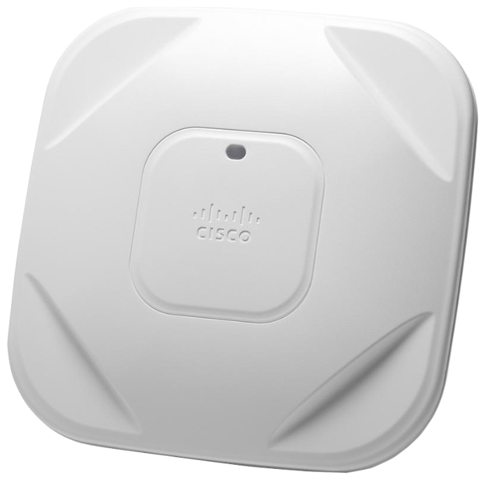
Cisco Aironet 1600 Series Access Points
About this Guide
Introduction to the Access Point
Safety Instructions
Unpacking
Configurations
External Antennas
Internal Antennas
Regulatory Domains
Access Point Ports and Connectors
Configuring the Access Point
The Controller Discovery Process
Preparing the Access Point
Installation Summary
Performing a Pre-Installation Configuration
Pre-Installation Configuration Setup
Mounting the Access Point
Deploying the Access Point on the Wireless Network
Troubleshooting
Guidelines for Using Cisco Aironet Lightweight Access Points
Using DHCP Option 43
Checking the Access Point LED
Troubleshooting the Access Point Join Process
Declarations of Conformity and Regulatory Information
Manufacturers Federal Communication Commission Declaration of Conformity Statement
VCCI Statement for Japan
Guidelines for Operating Cisco Aironet Access Points in Japan
Japanese Translation
English Translation
Statement 371—Power Cable and AC Adapter
English Translation
Industry Canada
Canadian Compliance Statement
European Community, Switzerland, Norway, Iceland, and Liechtenstein
Declaration of Conformity with regard to the R&TTE Directive 1999/5/EC & Medical Directive 93/42/EEC
Declaration of Conformity for RF Exposure
Generic Discussion on RF Exposure
This Device Meets International Guidelines for Exposure to Radio Waves
This Device Meets FCC Guidelines for Exposure to Radio Waves
This Device Meets the Industry Canada Guidelines for Exposure to Radio Waves
Cet appareil est conforme aux directives internationales en matière dqexposition aux fréquences radioélectriques
Additional Information on RF Exposure
Administrative Rules for Cisco Aironet Access Points in Taiwan
Chinese Translation
English Translation
Chinese Translation
English Translation
Operation of Cisco Aironet Access Points in Brazil
Access Point Models
Regulatory Information
Portuguese Translation
English Translation
Declaration of Conformity Statements
Access Point Specifications
Obtaining Documentation and Submitting a Service Request
Getting Started Guide
About this Guide
This Guide provides instructions on how to install and configure your Cisco Aironet 1600 Series Access Point. The 1600 Series Access Point is referred to as the 1600 series or the access point in this document.
Introduction to the Access Point
The 1600 series offers dual-band radios (2.4 GHz and 5 GHz) with integrated and external antenna options. The access points support full interoperability with leading 802.11n clients, and support a mixed deployment with other access points and controllers.
The 1600 series access point is available in controller-based mode and supports:
- Simultaneous single-band or dual-band (2.4 GHz/5 GHz) radios
- Integrated antennas on 1602I access point models (AIR-CAP1602I-x-K9)
- External antennas on 1602E access point models (AIR-CAP1602E-x-K9)

Note![]() The ‘x’ in the model numbers represents the regulatory domain. For information on supported regulatory domains, see “Regulatory Domains” section.
The ‘x’ in the model numbers represents the regulatory domain. For information on supported regulatory domains, see “Regulatory Domains” section.
The features of the 1600 series are:
- Processing sub-systems (including CPUs and memory) and radio hardware which supports:
–![]() Network management
Network management
–![]() ClientLink 2.0—BeamForming to 802.11n clients as well as legacy 802.11a/g OFDM clients
ClientLink 2.0—BeamForming to 802.11n clients as well as legacy 802.11a/g OFDM clients
–![]() VideoStream
VideoStream
–![]() Location
Location
–![]() WIDS/WIPS
WIDS/WIPS
–![]() Security
Security
–![]() Radio Resource Management (RRM)
Radio Resource Management (RRM)
–![]() Rogue detection
Rogue detection
–![]() Management Frame Protection (MFP)
Management Frame Protection (MFP)
- 32 MB flash size
- 802.11af/at
–![]() CDP (Cisco Discovery Protocol)
CDP (Cisco Discovery Protocol)
- 2.4 GHz and 5 GHz 802.11n radios with the following features:
–![]() 3TX x 3RX
3TX x 3RX
–![]() 2 spatial streams, 300 Mbps PHY rate
2 spatial streams, 300 Mbps PHY rate
–![]() DPD (Digital Pre-Distortion) technology
DPD (Digital Pre-Distortion) technology
–![]() Radio hardware is capable of explicit compressed beamforming (ECBF) per 802.11n standard
Radio hardware is capable of explicit compressed beamforming (ECBF) per 802.11n standard
Safety Instructions
Translated versions of the following safety warnings are provided in the translated safety warnings document that is shipped with your access point. The translated warnings are also in the Translated Safety Warnings for Cisco Aironet Access Points, which is available on Cisco.com.

Warning![]() IMPORTANT SAFETY INSTRUCTIONS
IMPORTANT SAFETY INSTRUCTIONS
This warning symbol means danger. You are in a situation that could cause bodily injury. Before you work on any equipment, be aware of the hazards involved with electrical circuitry and be familiar with standard practices for preventing accidents. Use the statement number provided at the end of each warning to locate its translation in the translated safety warnings that accompanied this device. Statement 1071
SAVE THESE INSTRUCTIONS
Warning![]() Read the installation instructions before you connect the system to its power source. Statement 1004
Read the installation instructions before you connect the system to its power source. Statement 1004
Warning![]() Installation of the equipment must comply with local and national electrical codes. Statement 1074
Installation of the equipment must comply with local and national electrical codes. Statement 1074
Warning![]() This product relies on the building’s installation for short-circuit (overcurrent) protection. Ensure that the protective device is rated not greater than:
This product relies on the building’s installation for short-circuit (overcurrent) protection. Ensure that the protective device is rated not greater than:
20A. Statement 1005
Warning![]() Do not operate your wireless network device near unshielded blasting caps or in an explosive environment unless the device has been modified to be especially qualified for such use. Statement 245B
Do not operate your wireless network device near unshielded blasting caps or in an explosive environment unless the device has been modified to be especially qualified for such use. Statement 245B
Warning![]() In order to comply with FCC radio frequency (RF) exposure limits, antennas should be located at a minimum of 7.9 inches (20 cm) or more from the body of all persons.
In order to comply with FCC radio frequency (RF) exposure limits, antennas should be located at a minimum of 7.9 inches (20 cm) or more from the body of all persons.
Statement 332

Caution
![]() The fasteners you use to mount an access point on a ceiling must be capable of maintaining a minimum pullout force of 20 lbs (9 kg) and must use all 4 indented holes on the mounting bracket.
The fasteners you use to mount an access point on a ceiling must be capable of maintaining a minimum pullout force of 20 lbs (9 kg) and must use all 4 indented holes on the mounting bracket.
Caution
![]() This product and all interconnected equipment must be installed indoors within the same building, including the associated LAN connections as defined by Environment A of the IEEE 802.af Standard.
This product and all interconnected equipment must be installed indoors within the same building, including the associated LAN connections as defined by Environment A of the IEEE 802.af Standard.
Note![]() The access point is suitable for use in environmental air space in accordance with section 300.22.C of the National Electrical Code and sections 2-128, 12-010(3), and 12-100 of the Canadian Electrical Code, Part 1, C22.1. You should not install the power supply or power injector in air handling spaces.
The access point is suitable for use in environmental air space in accordance with section 300.22.C of the National Electrical Code and sections 2-128, 12-010(3), and 12-100 of the Canadian Electrical Code, Part 1, C22.1. You should not install the power supply or power injector in air handling spaces.
Note![]() Use only with listed ITE equipment.
Use only with listed ITE equipment.
Unpacking
To unpack the access point, follow these steps:
Step 1![]() Unpack and remove the access point and the accessory kit from the shipping box.
Unpack and remove the access point and the accessory kit from the shipping box.
Step 2![]() Return any packing material to the shipping container and save it for future use.
Return any packing material to the shipping container and save it for future use.
Step 3![]() Verify that you have received the items listed below. If any item is missing or damaged, contact your Cisco representative or reseller for instructions.
Verify that you have received the items listed below. If any item is missing or damaged, contact your Cisco representative or reseller for instructions.
–![]() The access point
The access point
–![]() Mounting bracket (optional; selected when you ordered the access point)
Mounting bracket (optional; selected when you ordered the access point)
–![]() Adjustable ceiling-rail clip (optional; selected when you ordered the access point)
Adjustable ceiling-rail clip (optional; selected when you ordered the access point)
Configurations
The 1600 series access point contains two simultaneous dual-band radios, the 2.4-GHz and 5-GHz 802.11n MIMO radios, in controller-based mode. The radio configurations of the 1600 series access point are:
- AIR-CAP1602E-x-K9, AIR-SAP1602E-x-K9—controller-based mode, with two 2.4-GHz/5-GHz dual-band radios with up to 3 external dual-band dipole antennas
- AIR-CAP1602I-x-K9 and AIR-SAP1602I-x-K9—controller-based mode, with two 2.4-GHz/5-GHz dual-band radios, with integrated dual-band inverted-F antennas
For information on the regulatory domains (shown as “x” in the model numbers) see “Regulatory Domains” section.
External Antennas
The 1602E models are configured with up to three external dual-band dipole antennas, and two 2.4-GHz/5-GHz dual-band radios. The radios and antennas support frequency bands 2400–2500 MHz and 5150–5850 MHz through a common dual-band RF interface. Features of the external dual-band dipole antennas are:
- Three RTNC antenna connectors on the top of the access point
- Three TX and three RX antennas
These antennas are supported on the 1602E:
|
Antenna Part Number |
Antenna Type |
Antenna Gain 2 GHz / 5 GHz (dBi) |
|
AIR-ANT2524DB-R |
Dual-resonant black dipole |
2/4 |
|
AIR-ANT2524DW-R |
Dual-resonant white dipole |
2/4 |
|
AIR-ANT2524DG-R |
Dual-resonant gray dipole |
2/4 |
|
AIR-ANT2524V4C-R |
Dual-resonant, ceiling-mount omni (4-port) |
2/4 |
|
AIR-ANT2544V4M-R |
Dual-resonant omni (4-port) |
4/4 |
|
AIR-ANT2566P4W-R |
Dual-resonant Directional antenna (4-port) |
6/6 |
Internal Antennas
The 1602I model access points are configured with up to three dual-band inverted-F antennas and two 2.4-GHz/5-GHz dual-band radios.
Each antenna covers both the 2.4 GHz and the 5 GHz bands with a single feed line. The basic features are as follows:
- Dual-band inverted-F antenna for use in both the 2.4-GHz and 5-GHz bands.
- Antenna unit integrated into 1602I model access points.
- Peak gain is approximately 4 dBi in the 2.4-GHz band and approximately 4 dBi in the 5-GHz band.
Regulatory Domains
The 1600 series supports the following regulatory domains (shown as “x” in the model numbers):
- -A, -C, -E, -I, -K, -N, -Q, -R, -S, -T, -Z
Click this URL to see the last list of countries and regulatory domains supported by the 1600:
www.cisco.com/go/aironet/compliance
Access Point Ports and Connectors
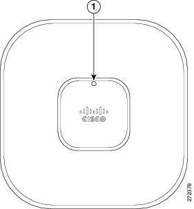
The 1602E model access points have external antenna connectors and the LED indictor on the top of the model, as shown in Figure 1. The 1602I model access points have integrated antennas and do not have external connectors on the top of the unit; however, they do have the LED indicator on top of the unit, as shown in Figure 2.
Figure 1 Access Point Ports and Connections (top)
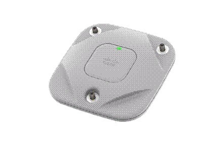
|
1 |
Antenna connector A |
3 |
Antenna connector C |
|
2 |
Antenna connector B |
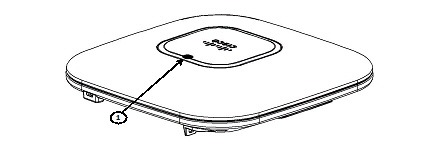
Figure 2 Access Point LED Indicator (top)
The ports and connections on the bottom of the access point are shown in Figure 3.
Figure 3 Access Point Ports and Connections (bottom)
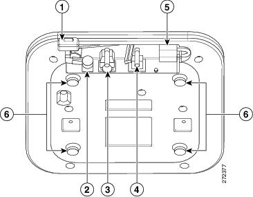
|
1 |
Kensington lock slot |
4 |
Console port |
|
2 |
DC Power connection |
5 |
Security padlock and hasp (padlock not included) |
|
3 |
Gbit Ethernet port |
6 |
Mounting bracket pins (feet for desk or table-top mount) |
Configuring the Access Point
This section describes how to connect the access point to a wireless LAN controller. Because the configuration process takes place on the controller, see the Cisco Wireless LAN Controller Configuration Guide for additional information. This guide is available on Cisco.com.
The Controller Discovery Process
The access point uses standard Control and Provisioning of Wireless Access Points Protocol (CAPWAP) to communicate between the controller and other wireless access points on the network.
CAPWAP is a standard, interoperable protocol which enables an access controller to manage a collection of wireless termination points. The discovery process using CAPWAP is identical to the Lightweight Access Point Protocol (LWAPP) used with previous Cisco Aironet access points. LWAPP-enabled access points are compatible with CAPWAP, and conversion to a CAPWAP controller is seamless. Deployments can combine CAPWAP and LWAPP software on the controllers.
The functionality provided by the controller does not change except for customers who have Layer 2 deployments, which CAPWAP does not support.
In a CAPWAP environment, a wireless access point discovers a controller by using CAPWAP discovery mechanisms and then sends it a CAPWAP join request. The controller sends the access point a CAPWAP join response allowing the access point to join the controller. When the access point joins the controller, the controller manages its configuration, firmware, control transactions, and data transactions.
Note![]() For additional information about the discovery process and CAPWAP, see the Cisco Wireless LAN Controller Software Configuration Guide. This document is available on Cisco.com.
For additional information about the discovery process and CAPWAP, see the Cisco Wireless LAN Controller Software Configuration Guide. This document is available on Cisco.com.
Note![]() CAPWAP support is provided in controller software release 5.2 or later. However, your controller must be running release 7.4.x.x or later to support 1600 series access points.
CAPWAP support is provided in controller software release 5.2 or later. However, your controller must be running release 7.4.x.x or later to support 1600 series access points.
Note![]() You cannot edit or query any access point using the controller CLI if the name of the access point contains a space.
You cannot edit or query any access point using the controller CLI if the name of the access point contains a space.
Note![]() Make sure that the controller is set to the current time. If the controller is set to a time that has already occurred, the access point might not join the controller because its certificate may not be valid for that time.
Make sure that the controller is set to the current time. If the controller is set to a time that has already occurred, the access point might not join the controller because its certificate may not be valid for that time.
Access points must be discovered by a controller before they can become an active part of the network. The access point supports these controller discovery processes:
- Layer 3 CAPWAP discovery—Can occur on different subnets than the access point and uses IP addresses and UDP packets rather than MAC addresses used by Layer 2 discovery.
- Locally stored controller IP address discovery—If the access point was previously joined to a controller, the IP addresses of the primary, secondary, and tertiary controllers are stored in the access point’s non-volatile memory. This process of storing controller IP addresses on an access point for later deployment is called priming the access point. For more information about priming, see the “Performing a Pre-Installation Configuration” section.
- DHCP server discovery—This feature uses DHCP option 43 to provide controller IP addresses to the access points. Cisco switches support a DHCP server option that is typically used for this capability. For more information about DHCP option 43, see the “Using DHCP Option 43” section.
- DNS discovery—The access point can discover controllers through your domain name server (DNS). For the access point to do so, you must configure your DNS to return controller IP addresses in response to CISCO-CAPWAP-CONTROLLER.localdomain, where localdomain is the access point domain name. Configuring the CISCO-CAPWAP-CONTROLLER provides backwards compatibility in an existing customer deployment. When an access point receives an IP address and DNS information from a DHCP server, it contacts the DNS to resolve CISCO-CAPWAP-CONTROLLER.localdomain. When the DNS sends a list of controller IP addresses, the access point sends discovery requests to the controllers.
Preparing the Access Point
Before you mount and deploy your access point, we recommend that you perform a site survey (or use the site planning tool) to determine the best location to install your access point.
You should have the following information about your wireless network available:
- Access point locations.
- Access point mounting options: below a suspended ceiling, on a flat horizontal surface, or on a desktop.
Note![]() You can mount the access point above a suspended ceiling but you must purchase additional mounting hardware: See “Mounting the Access Point” section for additional information.
You can mount the access point above a suspended ceiling but you must purchase additional mounting hardware: See “Mounting the Access Point” section for additional information.
- Access point power options: power supplied by the recommended external power supply (Cisco AIR-PWR-B), a DC power supply, PoE from a network device, or a PoE power injector/hub (usually located in a wiring closet).
Note![]() Access points mounted in a building’s environmental airspace must be powered using PoE to comply with safety regulations.
Access points mounted in a building’s environmental airspace must be powered using PoE to comply with safety regulations.
Cisco recommends that you make a site map showing access point locations so that you can record the device MAC addresses from each location and return them to the person who is planning or managing your wireless network.
Installation Summary
Installing the access point involves these operations:
- Performing a pre-installation configuration (optional)
- Mounting the access point
- Grounding the access point
- Deploying the access point on the wireless network
Performing a Pre-Installation Configuration
The following procedures ensure that your access point installation and initial operation go as expected. A pre-installation configuration is also known as priming the access point. This procedure is optional.
Note![]() Performing a pre-installation configuration is an optional procedure. If your network controller is properly configured, you can install your access point in its final location and connect it to the network from there. See the “Deploying the Access Point on the Wireless Network” section for details.
Performing a pre-installation configuration is an optional procedure. If your network controller is properly configured, you can install your access point in its final location and connect it to the network from there. See the “Deploying the Access Point on the Wireless Network” section for details.
Pre-Installation Configuration Setup
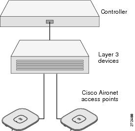
The pre-installation configuration setup is shown in Figure 4.
Figure 4 Pre-Installation Configuration Setup
To perform pre-installation configuration, perform the following steps:
Step 1![]() Make sure that the Cisco wireless LAN controller DS port is connected to the network. Use the CLI, web-browser interface, or Cisco Prime Infrastructure procedures as described in the appropriate Cisco wireless LAN controller guide.
Make sure that the Cisco wireless LAN controller DS port is connected to the network. Use the CLI, web-browser interface, or Cisco Prime Infrastructure procedures as described in the appropriate Cisco wireless LAN controller guide.
a.![]() Make sure that access points have Layer 3 connectivity to the Cisco wireless LAN controller Management Interface.
Make sure that access points have Layer 3 connectivity to the Cisco wireless LAN controller Management Interface.
b.![]() Configure the switch to which your access point is to attach. See the Cisco Wireless LAN Controller Configuration Guide for additional information.
Configure the switch to which your access point is to attach. See the Cisco Wireless LAN Controller Configuration Guide for additional information.
c.![]() Set the Cisco wireless LAN controller as the master so that new access points always join with it.
Set the Cisco wireless LAN controller as the master so that new access points always join with it.
d.![]() Make sure DHCP is enabled on the network. The access point must receive its IP address through DHCP.
Make sure DHCP is enabled on the network. The access point must receive its IP address through DHCP.
e.![]() CAPWAP UDP ports (5246 and 5247) must not be blocked in the network.
CAPWAP UDP ports (5246 and 5247) must not be blocked in the network.
f.![]() The access point must be able to find the IP address of the controller. This can be accomplished using DHCP, DNS, or IP subnet broadcast. This guide describes the DHCP method to convey the controller IP address. For other methods, refer to the product documentation. See also the “Using DHCP Option 43” section for more information.
The access point must be able to find the IP address of the controller. This can be accomplished using DHCP, DNS, or IP subnet broadcast. This guide describes the DHCP method to convey the controller IP address. For other methods, refer to the product documentation. See also the “Using DHCP Option 43” section for more information.
Step 2![]() Apply power to the access point:
Apply power to the access point:
a.![]() The access point is 802.3af (15.4 W) compliant and can be powered by any 802.3af compliant device.
The access point is 802.3af (15.4 W) compliant and can be powered by any 802.3af compliant device.
The recommended external power supply for the access point is the Cisco AIR-PWR-B power supply. The access point can also be powered by the following optional external power sources:
–![]() The AIR-PWRINJ4 power injector
The AIR-PWRINJ4 power injector
–![]() Any 802.3af compliant power injector
Any 802.3af compliant power injector
Note![]() The 1600 series access point requires a Gigibit Ethernet link to prevent the Ethernet port from becoming a bottleneck for traffic because wireless traffic speeds exceed transmit speeds of a 10/100 Ethernet port.
The 1600 series access point requires a Gigibit Ethernet link to prevent the Ethernet port from becoming a bottleneck for traffic because wireless traffic speeds exceed transmit speeds of a 10/100 Ethernet port.
b.![]() As the access point attempts to connect to the controller, the LEDs cycle through a green, red, and amber sequence, which can take up to 5 minutes.
As the access point attempts to connect to the controller, the LEDs cycle through a green, red, and amber sequence, which can take up to 5 minutes.
Note![]() If the access point remains in this mode for more than five minutes, the access point is unable to find the Master Cisco wireless LAN controller. Check the connection between the access point and the Cisco wireless LAN controller and be sure that they are on the same subnet.
If the access point remains in this mode for more than five minutes, the access point is unable to find the Master Cisco wireless LAN controller. Check the connection between the access point and the Cisco wireless LAN controller and be sure that they are on the same subnet.
c.![]() If the access point shuts down, check the power source.
If the access point shuts down, check the power source.
d.![]() After the access point finds the Cisco wireless LAN controller, it attempts to download the new operating system code if the access point code version differs from the Cisco wireless LAN controller code version. While this is happening, the Status LED blinks dark blue.
After the access point finds the Cisco wireless LAN controller, it attempts to download the new operating system code if the access point code version differs from the Cisco wireless LAN controller code version. While this is happening, the Status LED blinks dark blue.
e.![]() If the operating system download is successful, the access point reboots.
If the operating system download is successful, the access point reboots.
Step 3![]() Configure the access point if required. Use the controller CLI, controller GUI, or Cisco Prime Infrastructure to customize the access-point-specific 802.11n network settings.
Configure the access point if required. Use the controller CLI, controller GUI, or Cisco Prime Infrastructure to customize the access-point-specific 802.11n network settings.
Step 4![]() If the pre-installation configuration is successful, the Status LED is green indicating normal operation. Disconnect the access point and mount it at the location at which you intend to deploy it on the wireless network.
If the pre-installation configuration is successful, the Status LED is green indicating normal operation. Disconnect the access point and mount it at the location at which you intend to deploy it on the wireless network.
Step 5![]() If your access point does not indicate normal operation, turn it off and repeat the pre-installation configuration.
If your access point does not indicate normal operation, turn it off and repeat the pre-installation configuration.
Note![]() When you are installing a Layer 3 access point on a different subnet than the Cisco wireless LAN controller, be sure that a DHCP server is reachable from the subnet on which you will be installing the access point, and that the subnet has a route back to the Cisco wireless LAN controller. Also be sure that the route back to the Cisco wireless LAN controller has destination UDP ports 5246 and 5247 open for CAPWAP communications. Ensure that the route back to the primary, secondary, and tertiary wireless LAN controller allows IP packet fragments. Finally, be sure that if address translation is used, that the access point and the Cisco wireless LAN controller have a static 1-to-1 NAT to an outside address.
When you are installing a Layer 3 access point on a different subnet than the Cisco wireless LAN controller, be sure that a DHCP server is reachable from the subnet on which you will be installing the access point, and that the subnet has a route back to the Cisco wireless LAN controller. Also be sure that the route back to the Cisco wireless LAN controller has destination UDP ports 5246 and 5247 open for CAPWAP communications. Ensure that the route back to the primary, secondary, and tertiary wireless LAN controller allows IP packet fragments. Finally, be sure that if address translation is used, that the access point and the Cisco wireless LAN controller have a static 1-to-1 NAT to an outside address.
Deploying the Access Point on the Wireless Network
After you have mounted the access point, follow these steps to deploy it on the wireless network:
Step 1![]() Connect and power up the access point.
Connect and power up the access point.
Step 2![]() Observe the access point LED (for LED descriptions, see “Checking the Access Point LED” section).
Observe the access point LED (for LED descriptions, see “Checking the Access Point LED” section).
a.![]() When you power up the access point, it begins a power-up sequence that you can verify by observing the access point LED. If the power-up sequence is successful, the discovery and join process begins. During this process, the LED blinks sequentially green, red, and off. When the access point has joined a controller, the LED is green if no clients are associated or blue if one or more clients are associated.
When you power up the access point, it begins a power-up sequence that you can verify by observing the access point LED. If the power-up sequence is successful, the discovery and join process begins. During this process, the LED blinks sequentially green, red, and off. When the access point has joined a controller, the LED is green if no clients are associated or blue if one or more clients are associated.
b.![]() If the LED is not on, the access point is most likely not receiving power.
If the LED is not on, the access point is most likely not receiving power.
c.![]() If the LED blinks sequentially for more than 5 minutes, the access point is unable to find its primary, secondary, and tertiary Cisco wireless LAN controller. Check the connection between the access point and the Cisco wireless LAN controller, and be sure the access point and the Cisco wireless LAN controller are either on the same subnet or that the access point has a route back to its primary, secondary, and tertiary Cisco wireless LAN controller. Also, if the access point is not on the same subnet as the Cisco wireless LAN controller, be sure that there is a properly configured DHCP server on the same subnet as the access point. See the “Using DHCP Option 43” section for additional information.
If the LED blinks sequentially for more than 5 minutes, the access point is unable to find its primary, secondary, and tertiary Cisco wireless LAN controller. Check the connection between the access point and the Cisco wireless LAN controller, and be sure the access point and the Cisco wireless LAN controller are either on the same subnet or that the access point has a route back to its primary, secondary, and tertiary Cisco wireless LAN controller. Also, if the access point is not on the same subnet as the Cisco wireless LAN controller, be sure that there is a properly configured DHCP server on the same subnet as the access point. See the “Using DHCP Option 43” section for additional information.
Step 3![]() Reconfigure the Cisco wireless LAN controller so that it is not the Master.
Reconfigure the Cisco wireless LAN controller so that it is not the Master.
Note![]() A Master Cisco wireless LAN controller should be used only for configuring access points and not in a working network.
A Master Cisco wireless LAN controller should be used only for configuring access points and not in a working network.
Troubleshooting
If you experience difficulty getting your access point installed and running, look for a solution to your problem in this guide or in additional access point documentation. These, and other documents, are available on Cisco.com.
Guidelines for Using Cisco Aironet Lightweight Access Points
Keep these guidelines in mind when you use 1600 series lightweight access points:
- The access point can only communicate with Cisco wireless LAN controllers, such as 2500 series, 5500 series, and WiSM controllers.
- The access point does not support Wireless Domain Services (WDS) and cannot communicate with WDS devices. However, the controller provides functionality equivalent to WDS when the access point joins it.
- CAPWAP does not support Layer 2. The access point must get an IP address and discover the controller using Layer 3, DHCP, DNS, or IP subnet broadcast.
- The access point console port is enabled for monitoring and debug purposes. All configuration commands are disabled when the access point is connected to a controller.
Checking the Access Point LED
The location of the access point status LED is shown in Figure 5.
Note![]() Regarding LED status colors, it is expected that there will be small variations in color intensity and hue from unit to unit. This is within the normal range of the LED manufacturer’s specifications and is not a defect.
Regarding LED status colors, it is expected that there will be small variations in color intensity and hue from unit to unit. This is within the normal range of the LED manufacturer’s specifications and is not a defect.
Figure 5 Access Point LED Location
The access point status LED indicates various conditions and are described in Table 1.
|
Message |
Status |
Message Meaning |
|---|---|---|
|
Boot loader status sequence |
Blinking green |
DRAM memory test in progress |
|
DRAM memory test OK |
||
|
Board initialization in progress |
||
|
Initializing FLASH file system |
||
|
FLASH memory test OK |
||
|
Initializing Ethernet |
||
|
Ethernet OK |
||
|
Starting Cisco IOS |
||
|
Initialization successful |
||
|
Association status |
Blinking green |
Normal operating condition, but no wireless client associated |
|
Green |
Normal operating condition, at least one wireless client association |
|
|
Operating status |
Blinking amber |
Software upgrade in progress |
|
Cycling through green, red, and amber |
Discovery/join process in progress |
|
|
Rapidly cycling through red, green, and amber |
Access point location command invoked |
|
|
Blinking red |
Ethernet link not operational |
|
|
Boot loader warnings |
Blinking amber |
Configuration recovery in progress (MODE button pushed for 2 to 3 seconds) |
|
Red |
Ethernet failure or image recovery (MODE button pushed for 20 to 30 seconds) |
|
|
Blinking green |
Image recovery in progress (MODE button released) |
|
|
Boot loader errors |
Red |
DRAM memory test failure |
|
Blinking red and amber |
FLASH file system failure |
|
|
Blinking red and off |
Environment variable failure |
|
|
Bad MAC address |
||
|
Ethernet failure during image recovery |
||
|
Boot environment failure |
||
|
No Cisco image file |
||
|
Boot failure |
||
|
Cisco IOS errors |
Red |
Software failure; try disconnecting and reconnecting unit power |
|
Cycling through red, green, amber, and off |
General warning; insufficient inline power |
Troubleshooting the Access Point Join Process
Access points can fail to join a controller for many reasons: a RADIUS authorization is pending; self-signed certificates are not enabled on the controller; the access point’s and controller’s regulatory domains don’t match, and so on.
Controller software enables you to configure the access points to send all CAPWAP-related errors to a syslog server. You do not need to enable any debug commands on the controller because all of the CAPWAP error messages can be viewed from the syslog server itself.
The state of the access point is not maintained on the controller until it receives a CAPWAP join request from the access point. Therefore, it can be difficult to determine why the CAPWAP discovery request from a certain access point was rejected. In order to troubleshoot such joining problems without enabling CAPWAP debug commands on the controller, the controller collects information for all access points that send a discovery message to it and maintains information for any access points that have successfully joined it.
The controller collects all join-related information for each access point that sends a CAPWAP discovery request to the controller. Collection begins with the first discovery message received from the access point and ends with the last configuration payload sent from the controller to the access point.
An access point sends all syslog messages to IP address 255.255.255.255 by default when any of the following conditions are met:
- An access point running software release 5.2 or later has been newly deployed.
- An existing access point running software release 5.2 or later has been reset after clearing the configuration.
If any of these conditions are met and the access point has not yet joined a controller, you can also configure a DHCP server to return a syslog server IP address to the access point using option 7 on the server. The access point then starts sending all syslog messages to this IP address.
When the access point joins a controller for the first time, the controller sends the global syslog server IP address (the default is 255.255.255.255) to the access point. After that, the access point sends all syslog messages to this IP address until it is overridden by one of the following scenarios:
- The access point is still connected to the same controller, and the global syslog server IP address configuration on the controller has been changed using the config ap syslog host global syslog_server_IP_address command. In this case, the controller sends the new global syslog server IP address to the access point.
- The access point is still connected to the same controller, and a specific syslog server IP address has been configured for the access point on the controller using the config ap syslog host specific Cisco_AP syslog_server_IP_address command. In this case, the controller sends the new specific syslog server IP address to the access point.
- The access point is disconnected from the controller and joins another controller. In this case, the new controller sends its global syslog server IP address to the access point.
- Whenever a new syslog server IP address overrides the existing syslog server IP address, the old address is erased from persistent storage, and the new address is stored in its place. The access point also starts sending all syslog messages to the new IP address provided the access point can reach the syslog server IP address.
You can configure the syslog server for access points and view the access point join information only from the controller CLI.
A detailed explanation of the join process is on Cisco.com at the following URL:
http://www.Cisco.com/en/US/products/ps6366/products_tech_note09186a00808f8599.shtml
Declarations of Conformity and Regulatory Information
This section provides declarations of conformity and regulatory information for Cisco Aironet 1600 Series Access Points. You can find additional information at this URL:
www.cisco.com/go/aironet/compliance
Manufacturers Federal Communication Commission Declaration of Conformity Statement

|
Models |
Certification Numbers |
|---|---|
|
AIR-SAP1602I-A-K9 AIR-SAP1602I-B-K9 |
LDK102084 |
Manufacturer:
Cisco Systems, Inc.
170 West Tasman Drive
San Jose, CA 95134-1706
USA
This device complies with Part 15 rules. Operation is subject to the following two conditions:
1.![]() This device may not cause harmful interference, and
This device may not cause harmful interference, and
2.![]() This device must accept any interference received, including interference that may cause undesired operation.
This device must accept any interference received, including interference that may cause undesired operation.
This device operates in the 5150-5250MHz and 5470-5725MHz bands and is therefore restricted to indoor operation only per FCC guidance.
This equipment has been tested and found to comply with the limits of a Class B digital device, pursuant to Part 15 of the FCC Rules. These limits are designed to provide reasonable protection against harmful interference when the equipment is operated in a residential environment. This equipment generates, uses, and radiates radio frequency energy, and if not installed and used in accordance with the instructions, may cause harmful interference. However, there is no guarantee that interference will not occur. If this equipment does cause interference to radio or television reception, which can be determined by turning the equipment off and on, the user is encouraged to correct the interference by one of the following measures:
- Reorient or relocate the receiving antenna.
- Increase separation between the equipment and receiver.
- Connect the equipment to an outlet on a circuit different from which the receiver is connected.
- Consult the dealer or an experienced radio/TV technician.
Caution
![]() The Part 15 radio device operates on a non-interference basis with other devices operating at this frequency when using the integrated antennas. Any changes or modification to the product not expressly approved by Cisco could void the user’s authority to operate this device.
The Part 15 radio device operates on a non-interference basis with other devices operating at this frequency when using the integrated antennas. Any changes or modification to the product not expressly approved by Cisco could void the user’s authority to operate this device.
Caution
![]() Within the 5.15 to 5.25 GHz and 5.47-5.725 GHz bands, this device is restricted to indoor operations to reduce any potential for harmful interference to co-channel Mobile Satellite System (MSS) operations.
Within the 5.15 to 5.25 GHz and 5.47-5.725 GHz bands, this device is restricted to indoor operations to reduce any potential for harmful interference to co-channel Mobile Satellite System (MSS) operations.
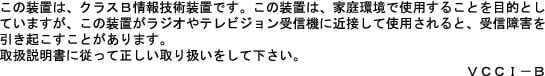
VCCI Statement for Japan
|
Warning |
This is a Class B product based on the standard of the Voluntary Control Council for Interference from Information Technology Equipment (VCCI). If this is used near a radio or television receiver in a domestic environment, it may cause radio interference. Install and use the equipment according to the instruction manual. |
|
|
|

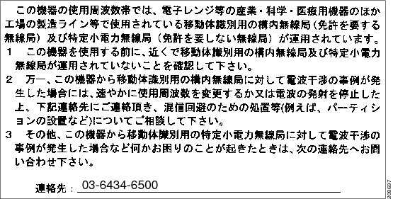
Guidelines for Operating Cisco Aironet Access Points in Japan
This section provides guidelines for avoiding interference when operating Cisco Aironet access points in Japan. These guidelines are provided in both Japanese and English.
Japanese Translation
English Translation
This equipment operates in the same frequency bandwidth as industrial, scientific, and medical devices such as microwave ovens and mobile object identification (RF-ID) systems (licensed premises radio stations and unlicensed specified low-power radio stations) used in factory production lines.
1.![]() Before using this equipment, make sure that no premises radio stations or specified low-power radio stations of RF-ID are used in the vicinity.
Before using this equipment, make sure that no premises radio stations or specified low-power radio stations of RF-ID are used in the vicinity.
2.![]() If this equipment causes RF interference to a premises radio station of RF-ID, promptly change the frequency or stop using the device; contact the number below and ask for recommendations on avoiding radio interference, such as setting partitions.
If this equipment causes RF interference to a premises radio station of RF-ID, promptly change the frequency or stop using the device; contact the number below and ask for recommendations on avoiding radio interference, such as setting partitions.
3.![]() If this equipment causes RF interference to a specified low-power radio station of RF-ID, contact the number below.
If this equipment causes RF interference to a specified low-power radio station of RF-ID, contact the number below.
Contact Number: 03-6434-6500
Statement 371—Power Cable and AC Adapter

English Translation
When installing the product, please use the provided or designated connection cables/power cables/AC adaptors. Using any other cables/adaptors could cause a malfunction or a fire. Electrical Appliance and Material Safety Law prohibits the use of UL-certified cables (that have the “UL” shown on the code) for any other electrical devices than products designated by CISCO. The use of cables that are certified by Electrical Appliance and Material Safety Law (that have “PSE” shown on the code) is not limited to CISCO-designated products.
Industry Canada
Canadian Compliance Statement
|
Models |
Certification Numbers |
|---|---|
|
AIR-SAP1602I-A-K9 |
2461B-102084 |
This Class B Digital apparatus meets all the requirements of the Canadian Interference-Causing Equipment Regulations.
Cet appareil numerique de la classe B respecte les exigences du Reglement sur le material broilleur du Canada.
This device complies with Class B Limits of Industry Canada. Operation is subject to the following two conditions:
1.![]() This device may not cause harmful interference, and
This device may not cause harmful interference, and
2.![]() This device must accept any interference received, including interference that may cause undesired operation.
This device must accept any interference received, including interference that may cause undesired operation.
Cisco Aironet Access Points are certified to the requirements of RSS-210. The use of this device in a system operating either partially or completely outdoors may require the user to obtain a license for the system according to the Canadian regulations. For further information, contact your local Industry Canada office.
This device has been designed to operate with antennas having a maximum gain of 6 dBi. Antennas having a gain greater than 6 dBi are strictly prohibited for use with this device. The required antenna impedance is 50 ohms.
To reduce potential radio interference to other users, the antenna type and its gain should be so chosen that the equivalent isotropically radiated power (EIRP) is not more than that permitted for successful communication.
European Community, Switzerland, Norway, Iceland, and Liechtenstein
Models:
AIR-SAP1602I-E-K9
AIR-SAP1602E-E-K9
AIR-CAP1602I-E-K9
AIR-CAP1602E-E-K9
AIR-CLD1602I-E-K9
Declaration of Conformity with regard to the R&TTE Directive 1999/5/EC & Medical Directive 93/42/EEC
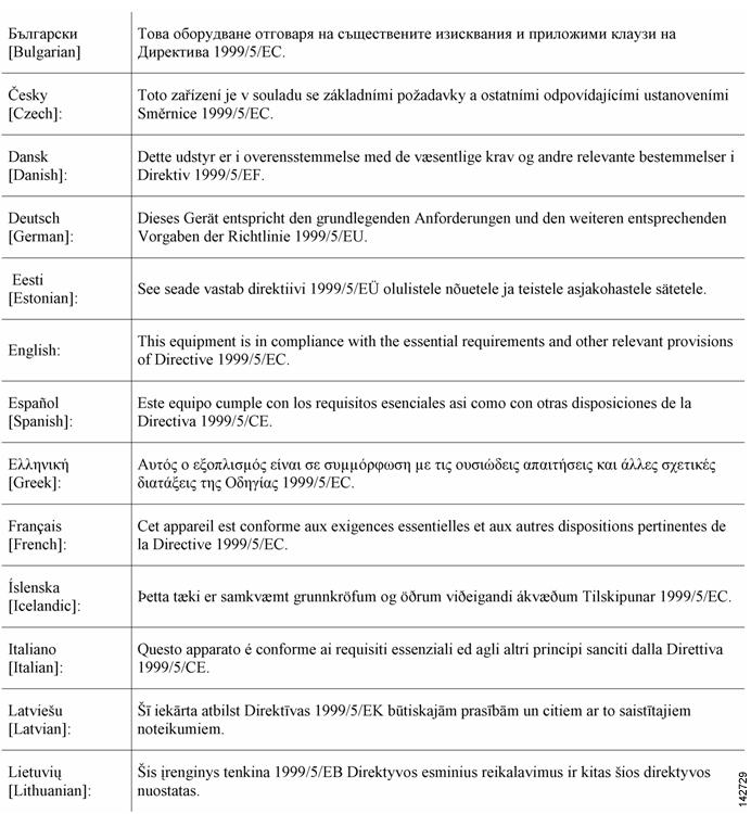

The following standards were applied:
EMC—EN 301.489-1 v1.8.1; EN 301.489-17 v2.1.1
Health & Safety—EN60950-1: 2005; EN 50385: 2002
Radio—EN 300 328 v 1.7.1; EN 301.893 v 1.5.1
The conformity assessment procedure referred to in Article 10.4 and Annex III of Directive 1999/5/EC has been followed.
This device also conforms to the EMC requirements of the Medical Devices Directive 93/42/EEC.
Note![]() This equipment is intended to be used in all EU and EFTA countries. Outdoor use may be restricted to certain frequencies and/or may require a license for operation. For more details, contact Cisco Corporate Compliance.
This equipment is intended to be used in all EU and EFTA countries. Outdoor use may be restricted to certain frequencies and/or may require a license for operation. For more details, contact Cisco Corporate Compliance.
For 1600 series access points, the following CE mark and Class-2 identifier are affixed to the equipment and its packaging:

Declaration of Conformity for RF Exposure
This section contains information on compliance with guidelines related to RF exposure.
Generic Discussion on RF Exposure
The Cisco products are designed to comply with the following national and international standards on Human Exposure to Radio Frequencies:
- US 47 Code of Federal Regulations Part 2 Subpart J
- American National Standards Institute (ANSI) / Institute of Electrical and Electronic Engineers / IEEE C 95.1 (99)
- International Commission on Non Ionizing Radiation Protection (ICNIRP) 98
- Ministry of Health (Canada) Safety Code 6. Limits on Human Exposure to Radio Frequency Fields in the range from 3kHz to 300 GHz
- Australia Radiation Protection Standard
To ensure compliance with various national and international Electromagnetic Field (EMF) standards, the system should only be operated with Cisco approved antennas and accessories.
This Device Meets International Guidelines for Exposure to Radio Waves
The 1600 series device includes a radio transmitter and receiver. It is designed not to exceed the limits for exposure to radio waves (radio frequency electromagnetic fields) recommended by international guidelines. The guidelines were developed by an independent scientific organization (ICNIRP) and include a substantial safety margin designed to ensure the safety of all persons, regardless of age and health.
As such the systems are designed to be operated as to avoid contact with the antennas by the end user. It is recommended to set the system in a location where the antennas can remain at least a minimum distance as specified from the user in accordance to the regulatory guidelines which are designed to reduce the overall exposure of the user or operator.
|
Separation Distance |
||
|---|---|---|
|
MPE |
Distance |
Limit |
|
0.63 mW/cm2 |
20 cm (7.87 inches) |
1.00 mW/cm2 |
The World Health Organization has stated that present scientific information does not indicate the need for any special precautions for the use of wireless devices. They recommend that if you are interested in further reducing your exposure then you can easily do so by reorienting antennas away from the user or placing he antennas at a greater separation distance then recommended.
This Device Meets FCC Guidelines for Exposure to Radio Waves
The 1600 series device includes a radio transmitter and receiver. It is designed not to exceed the limits for exposure to radio waves (radio frequency electromagnetic fields) as referenced in FCC Part 1.1310. The guidelines are based on IEEE ANSI C 95.1 (92) and include a substantial safety margin designed to ensure the safety of all persons, regardless of age and health.
As such the systems are designed to be operated as to avoid contact with the antennas by the end user. It is recommended to set the system in a location where the antennas can remain at least a minimum distance as specified from the user in accordance to the regulatory guidelines which are designed to reduce the overall exposure of the user or operator.
The device has been tested and found compliant with the applicable regulations as part of the radio certification process.
|
Separation Distance |
||
|---|---|---|
|
MPE |
Distance |
Limit |
|
0.63 mW/cm2 |
20 cm (7.87 inches) |
1.00 mW/cm2 |
The US Food and Drug Administration has stated that present scientific information does not indicate the need for any special precautions for the use of wireless devices. The FCC recommends that if you are interested in further reducing your exposure then you can easily do so by reorienting antennas away from the user or placing the antennas at a greater separation distance then recommended or lowering the transmitter power output.
This Device Meets the Industry Canada Guidelines for Exposure to Radio Waves
The 1600 series device includes a radio transmitter and receiver. It is designed not to exceed the limits for exposure to radio waves (radio frequency electromagnetic fields) as referenced in Health Canada Safety Code 6. The guidelines include a substantial safety margin designed into the limit to ensure the safety of all persons, regardless of age and health.
As such the systems are designed to be operated as to avoid contact with the antennas by the end user. It is recommended to set the system in a location where the antennas can remain at least a minimum distance as specified from the user in accordance to the regulatory guidelines which are designed to reduce the overall exposure of the user or operator.
|
Separation Distance |
||
|---|---|---|
|
MPE |
Distance |
Limit |
|
0.63 mW/cm2 |
20 cm (7.87 inches) |
1.00 mW/cm2 |
Health Canada states that present scientific information does not indicate the need for any special precautions for the use of wireless devices. They recommend that if you are interested in further reducing your exposure you can easily do so by reorienting antennas away from the user, placing the antennas at a greater separation distance than recommended, or lowering the transmitter power output.
Cet appareil est conforme aux directives internationales en matière d’exposition aux fréquences radioélectriques
Cet appareil de la gamme 1700 comprend un émetteur-récepteur radio. Il a été conçu de manière à respecter les limites en matière d’exposition aux fréquences radioélectriques (champs électromagnétiques de fréquence radio), recommandées dans le code de sécurité 6 de Santé Canada. Ces directives intègrent une marge de sécurité importante destinée à assurer la sécurité de tous, indépendamment de l’âge et de la santé.
Par conséquent, les systèmes sont conçus pour être exploités en évitant que l’utilisateur n’entre en contact avec les antennes. Il est recommandé de poser le système là où les antennes sont à une distance minimale telle que précisée par l’utilisateur conformément aux directives réglementaires qui sont conçues pour réduire l’exposition générale de l’utilisateur ou de l’opérateur.
|
Distance d’éloignement |
||
|---|---|---|
|
MPE |
Distance |
Limite |
|
0.63 mW/cm2 |
20 cm (7.87 po) |
1.00 mW/cm2 |
Santé Canada affirme que la littérature scientifique actuelle n’indique pas qu’il faille prendre des précautions particulières lors de l’utilisation d’un appareil sans fil. Si vous voulez réduire votre exposition encore davantage, selon l’agence, vous pouvez facilement le faire en réorientant les antennes afin qu’elles soient dirigées à l’écart de l’utilisateur, en les plaçant à une distance d’éloignement supérieure à celle recommandée ou en réduisant la puissance de sortie de l’émetteur.
Additional Information on RF Exposure
You can find additional information on the subject at the following links:
- Cisco Systems Spread Spectrum Radios and RF Safety white paper at this URL:
http://www.cisco.com/warp/public/cc/pd/witc/ao340ap/prodlit/rfhr_wi.htm - FCC Bulletin 56: Questions and Answers about Biological Effects and Potential Hazards of Radio Frequency Electromagnetic Fields
- FCC Bulletin 65: Evaluating Compliance with the FCC guidelines for Human Exposure to Radio Frequency Electromagnetic Fields
- FCC Bulletin 65C (01-01): Evaluating Compliance with the FCC guidelines for Human Exposure to Radio Frequency Electromagnetic Fields: Additional Information for Evaluating Compliance for Mobile and Portable Devices with FCC limits for Human Exposure to Radio Frequency Emission
You can obtain additional information from the following organizations:
- World Health Organization Internal Commission on Non-Ionizing Radiation Protection at this URL: www.who.int/emf
- United Kingdom, National Radiological Protection Board at this URL: www.nrpb.org.uk
- Cellular Telecommunications Association at this URL: www.wow-com.com
- The Mobile Manufacturers Forum at this URL: www.mmfai.org
Administrative Rules for Cisco Aironet Access Points in Taiwan
This section provides administrative rules for operating Cisco Aironet access points in Taiwan. The rules for all access points are provided in both Chinese and English.
Chinese Translation
English Translation
Administrative Rules for Low-power Radio-Frequency Devices
Article 12
For those low-power radio-frequency devices that have already received a type-approval, companies, business units or users should not change its frequencies, increase its power or change its original features and functions.
Article 14
The operation of the low-power radio-frequency devices is subject to the conditions that no harmful interference is caused to aviation safety and authorized radio station; and if interference is caused, the user must stop operating the device immediately and can’t re-operate it until the harmful interference is clear.
The authorized radio station means a radio-communication service operating in accordance with the Communication Act.
The operation of the low-power radio-frequency devices is subject to the interference caused by the operation of an authorized radio station, by another intentional or unintentional radiator, by industrial, scientific and medical (ISM) equipment, or by an incidental radiator.
Chinese Translation
English Translation
Low-power Radio-frequency Devices Technical Specifications
|
4.7 |
Unlicensed National Information Infrastructure |
|
4.7.5 |
Within the 5.25-5.35 GHz band, U-NII devices will be restricted to indoor operations to reduce any potential for harmful interference to co-channel MSS operations. |
|
4.7.6 |
The U-NII devices shall accept any interference from legal communications and shall not interfere the legal communications. If interference is caused, the user must stop operating the device immediately and can’t re-operate it until the harmful interference is clear. |
|
4.7.7 |
Manufacturers of U-NII devices are responsible for ensuring frequency stability such that an emission is maintained within the band of operation under all conditions of normal operation as specified in the user manual. |
Operation of Cisco Aironet Access Points in Brazil
This section contains special information for operation of Cisco Aironet access points in Brazil.
Access Point Models
AIR-SAP1602I-T-K9
AIR-SAP1602E-T-K9
AIR-CAP1602I-T-K9
AIR-CAP1602E-T-K9
AIR-CLD1602I-T-K9
Regulatory Information
Figure 6 contains Brazil regulatory information for the access point models identified in the previous section.
Figure 6 Brazil Regulatory Information

Portuguese Translation
Este equipamento opera em caráter secundário, isto é, não tem direito a proteção contra interferência prejudicial, mesmo de estações do mesmo tipo, e não pode causar interferência a sistemas operando em caráter primário.
English Translation
This equipment operates on a secondary basis and consequently must accept harmful interference, including interference from stations of the same kind. This equipment may not cause harmful interference to systems operating on a primary basis.
Declaration of Conformity Statements
All the Declaration of Conformity statements related to this product can be found at the following location: http://www.ciscofax.com
Obtaining Documentation and Submitting a Service Request
For information on obtaining documentation, submitting a service request, and gathering additional information, see the monthly What’s New in Cisco Product Documentation, which also lists all new and revised Cisco technical documentation, at:
http://www.cisco.com/en/US/docs/general/whatsnew/whatsnew.html
Subscribe to the What’s New in Cisco Product Documentation as an RSS feed and set content to be delivered directly to your desktop using a reader application. The RSS feeds are a free service. Cisco currently supports RSS Version 2.0.
- Инструкции и руководства
- Бренды
- Cisco
- Aironet 1602I
![]()
Модели
AIR-CAP1602I-E-K9Показать ещё
, AIR-SAP1602I-AK9-5, AIR-CAP1602I-AK910, AIR-SAP1602I-A-K9, AIR-CAP1602I-A-K9, AIR-CAP1602I-EK910, AIR-SAP1602I-EK9-5, AIR-SAP1602I-N-K9, AIR-CAP1602I-N-K9, AIR-SAP1602I-C-K9, AIR-SAP1602I-I-K9, AIR-CAP1602I-C-K9, AIR-SAP1602I-R-K9, AIR-CAP1602I-I-K9, AIR-SAP1602I-T-K9, AIR-CAP1602I-K-K9
Скрыть
Техническая Спецификация (English)Техническая Спецификация (English)Техническая Спецификация (English)Техническая Спецификация (English)Техническая Спецификация (English)Техническая Спецификация (English)Техническая Спецификация (English)Техническая Спецификация (English)Техническая Спецификация (English)Техническая Спецификация (English)Техническая Спецификация (English)Техническая Спецификация (English)Техническая Спецификация (English)Техническая Спецификация (English)Техническая Спецификация (English)Техническая Спецификация (English)
Рейтинг точки доступа:
(5 — 1 голос)
Дать ссылку друзьям:
Рейтинг: Пока без рейтинга
Наличие инструкции подключения и альтернативной прошивки: В наличии
Настройка подключения
На данной странице вы узнаете как подключить Wi-Fi маршрутизатор к компьютеру, а также сможете найти инструкцию по настройке на русском языке.
Сотрудники нашего информационного портала ежедневно обновляют официальные прошивки для той или иной модели устройства.
Настройка Вай-Фай
Пошаговая настройка роутера Cisco AIR-CAP1602I для Ростелеком, Билайн и других интернет провайдеров займет у Вас несколько минут и после этого вы сможете наслаждаться всеми достоинствами Wi-Fi точки доступа Циско.
Настройка IPTV
Если вы хотите получить последнюю версию официальной прошивки и инструкцию по подключению VPN или PPPOE и настройка IPTV телевидения для этого устройства на русском языке на ваш Email, то вам следует оставить полный, развернутый отзыв о той или иной модели Вай-Фай устройства.
Скачать прошивку для маршрутизатораЧтобы скачать прошивку для Cisco AIR-CAP1602I вам достаточно внимательно ознакомиться со страницей, на которой вы сейчас находитесь. Не забывайте оставлять свои отзывы (форма для добавления отзывов находится в нижней части страницы). Если вас не затруднит, то вы можете поделиться ссылкой на прошивку со своими друзьями. Также, если вы не нашли ответ на свой вопрос, то вы можете задать его воспользовавшись формой в нижней части сайта. У нас вы найдете последние версии драйверов для беспроводных устройств. Чтобы скачать новый драйвер, вам необходимо перейти по ссылке «Скачать прошивку», которая расположена чуть ниже.
Скачать прошивку Настройки роутера Видео как настроить Cisco AIR-CAP1602I |
|
![]()
GETTING STARTED GUIDE
Cisco Aironet 1600 Series Access Points
December, 2012
Revised: April 16, 2013
1About this Guide
2Introduction to the Access Point
3Safety Instructions
4Unpacking
5Configurations
6Access Point Ports and Connectors
7Configuring the Access Point
8Mounting the Access Point
9Deploying the Access Point on the Wireless Network
10Troubleshooting
11Declarations of Conformity and Regulatory Information
12Access Point Specifications

1 About this Guide
This Guide provides instructions on how to install and configure your Cisco Aironet 1600 Series Access Point. The 1600 Series Access Point is referred to as the 1600 series or the access point in this document.
2 Introduction to the Access Point
The 1600 series offers dual-band radios (2.4 GHz and 5 GHz) with integrated and external antenna options. The access points support full inter-operability with leading 802.11n clients, and support a mixed deployment with other access points and controllers.
The 1600 series access point is available in controller-based mode and in cloud-enabled mode and supports:
•Simultaneous single-band or dual-band (2.4 GHz/5 GHz) radios
•Integrated antennas on 1602I access point models (AIR-CAP1602I-x-K9)
•External antennas on 1602E access point models (AIR-CAP1602E-x-K9)
Note The ‘x’ in the model numbers represents the regulatory domain. Refer to “Regulatory Domains” section on page 6 for a list of supported regulatory domains.
The features of the 1600 series are:
•Processing sub-systems (including CPUs and memory) and radio hardware which supports:
–Network management
–ClientLink 2.0—BeamForming to 802.11n clients as well as legacy 802.11a/g OFDM clients
–VideoStream
–Location
–WIDS/WIPS
–Security
–Radio Resource Management (RRM)
–Rogue detection
–Management Frame Protection (MFP)
–Cloud-based mode (on AIR-CLD1602I-x-K9 models)
•32 MB flash size
2

•802.11af/at
–CDP (Cisco Discovery Protocol)
•2.4 GHz and 5 GHz 802.11n radios with the following features:
–3TX x 3RX
–2 spatial streams, 300 Mbps PHY rate
–DPD (Digital Pre-Distortion) technology
–Radio hardware is capable of explicit compressed beamforming (ECBF) per 802.11n standard
3 Safety Instructions
Translated versions of the following safety warnings are provided in the translated safety warnings document that is shipped with your access point. The translated warnings are also in the Translated Safety Warnings for Cisco Aironet Access Points, which is available on Cisco.com.
|
Warning |
IMPORTANT SAFETY INSTRUCTIONS |
This warning symbol means danger. You are in a situation that could cause bodily injury. Before you work on any equipment, be aware of the hazards involved with electrical circuitry and be familiar with standard practices for preventing accidents. Use the statement number provided at the end of each warning to locate its translation in the translated safety warnings that accompanied this device. Statement 1071
SAVE THESE INSTRUCTIONS
Read the installation instructions before you connect the system to its power source.
Statement 1004
Installation of the equipment must comply with local and national electrical codes.
Statement 1074
This product relies on the building’s installation for short-circuit (overcurrent) protection. Ensure that the protective device is rated not greater than:
20A. Statement 1005
3

|
Warning |
Do not operate your wireless network device near unshielded blasting caps or in an |
||
|
explosive environment unless the device has been modified to be especially qualified for |
|||
|
such use. Statement 245B |
|||
|
Warning |
In order to comply with FCC radio frequency (RF) exposure limits, antennas should be |
||
|
located at a minimum of 7.9 inches (20 cm) or more from the body of all persons. |
|||
|
Statement 332 |
|||
|
Caution |
The fasteners you use to mount an access point on a ceiling must be capable of |
||
|
maintaining a minimum pullout force of 20 lbs (9 kg) and must use all 4 indented holes |
|||
|
on the mounting bracket. |
|||
|
Caution |
This product and all interconnected equipment must be installed indoors within the same |
||
|
building, including the associated LAN connections as defined by Environment A of the |
|||
|
IEEE 802.af Standard. |
|||
Note The access point is suitable for use in environmental air space in accordance with section 300.22.C of the National Electrical Code and sections 2-128, 12-010(3), and 12-100 of the Canadian Electrical Code, Part 1, C22.1. You should not install the power supply or power injector in air handling spaces.
Note Use only with listed ITE equipment.
4 Unpacking
To unpack the access point, follow these steps:
Step 1 Unpack and remove the access point and the accessory kit from the shipping box.
Step 2 Return any packing material to the shipping container and save it for future use.
4

Step 3 Verify that you have received the items listed below. If any item is missing or damaged, contact your Cisco representative or reseller for instructions.
–The access point
–Mounting bracket (optional; selected when you ordered the access point)
–Adjustable ceiling-rail clip (optional; selected when you ordered the access point)
5 Configurations
The 1600 series access point contains two simultaneous dual-band radios, the 2.4-GHz and 5-GHz 802.11n MIMO radios, in controller-based mode and in cloud-based mode. The 1600 series access point configurations are:
•AIR-CAP1602E-x-K9 and AIR-SAP1602E-x-K9—controller-based mode, with two 2.4-GHz/5-GHz dual-band radios with up to 3 external dual-band dipole antennas
•AIR-CAP1602I-x-K9 and AIR-SAP1602I-x-K9—controller-based mode, with two 2.4-GHz/5-GHz dual-band radios, with integrated dual-band inverted-F antennas
•AIR-CLD1602I-x-K9—cloud-based mode, with two 2.4-GHz/5-GHz dual-band radios, with integrated dual-band inverted-F antennas
For information on the regulatory domains (shown as “x” in the model numbers) see “Regulatory Domains” section on page 6.
External Antennas
The 1602E models are configured with up to three external dual-band dipole antennas, and two 2.4-GHz/5-GHz dual-band radios. The radios and antennas support frequency bands 2400–2500 MHz and 5150–5850 MHz through a common dual-band RF interface. Features of the external dual-band dipole antennas are:
•Three RTNC antenna connectors on the top of the access point
•Three TX and three RX antennas
These antennas are supported on the 1602E:
|
Antenna Part Number |
Antenna Type |
Antenna Gain 2 GHz / 5 GHz |
|
(dBi) |
||
|
AIR-ANT2524DB-R |
Dual-resonant black dipole |
2/4 |
|
AIR-ANT2524DW-R |
Dual-resonant white dipole |
2/4 |
5
|
AIR-ANT2524DG-R |
Dual-resonant gray dipole |
2/4 |
|
AIR-ANT2524V4C-R |
Dual-resonant, ceiling-mount omni |
2/4 |
|
(4-port) |
||
|
AIR-ANT2544V4M-R |
Dual-resonant omni (4-port) |
4/4 |
|
AIR-ANT2566P4W-R |
Dual-resonant Directional antenna |
6/6 |
|
(4-port) |
||
Internal Antennas
The 1602I model access points are configured with up to three dual-band inverted-F antennas and two 2.4-GHz/5-GHz dual-band radios.
Each antenna covers both the 2.4 GHz and the 5 GHz bands with a single feed line. The basic features are as follows:
•Dual-band inverted-F antenna for use in both the 2.4-GHz and 5-GHz bands.
•Antenna unit integrated into 1602I model access points.
•Peak gain is approximately 4 dBi in the 2.4-GHz band and approximately 4 dBi in the 5-GHz band.
Regulatory Domains
The 1600 series supports the following regulatory domains (shown as “x” in the model numbers):
• -A, -C, -E, -I, -K, -N, -Q, -R, -S, -T, -Z
Countries Supported
Click this URL to browse to a list of countries and regulatory domains supported by the 1600:
www.cisco.com/go/aironet/compliance
6 Access Point Ports and Connectors
The 1602E model access points have external antenna connectors and the LED indictor on the top of the model, as shown in Figure 1. The 1602I model access points have integrated antennas and do not have external connectors on the top of the unit; however, they do have the LED indicator on top of the unit, as shown in Figure 2.
6
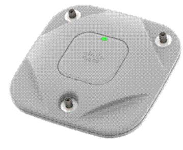
Figure 1 Access Point Ports and Connections (top)
|
1 |
Antenna connector A |
3 |
Antenna connector C |
|
2 |
Antenna connector B |
||
7

Figure 2 Access Point LED Indicator (top)
1
1 LED indicator
The ports and connections on the bottom of the access point are shown in Figure 3.
Figure 3 Access Point Ports and Connections (bottom)
272377
2 3 4
8

|
1 |
Kensington lock slot |
4 |
Console port |
|
2 |
DC Power connection |
5 |
Security padlock and hasp (padlock not |
|
included) |
|||
|
3 |
Gbit Ethernet port |
6 |
Mounting bracket pins (feet for desk or |
|
table-top mount) |
|||
7 Configuring the Access Point
This section describes how to connect the access point to a wireless LAN controller. Because the configuration process takes place on the controller, see the Cisco Wireless LAN Controller Configuration Guide for additional information. This guide is available on Cisco.com.
Note Cloud-enabled access points look for the Cisco-hosted cloud service as soon as you plug it into your network. You use the Cisco-hosted cloud portal to claim, configure, monitor, and troubleshoot the access point.
The Controller Discovery Process
The access point uses standard Control and Provisioning of Wireless Access Points Protocol (CAPWAP) to communicate between the controller and other wireless access points on the network.
CAPWAP is a standard, interoperable protocol which enables an access controller to manage a collection of wireless termination points. The discovery process using CAPWAP is identical to the Lightweight Access Point Protocol (LWAPP) used with previous Cisco Aironet access points. LWAPP-enabled access points are compatible with CAPWAP, and conversion to a CAPWAP controller is seamless. Deployments can combine CAPWAP and LWAPP software on the controllers.
The functionality provided by the controller does not change except for customers who have Layer 2 deployments, which CAPWAP does not support.
In a CAPWAP environment, a wireless access point discovers a controller by using CAPWAP discovery mechanisms and then sends it a CAPWAP join request. The controller sends the access point a CAPWAP join response allowing the access point to join the controller. When the access point joins the controller, the controller manages its configuration, firmware, control transactions, and data transactions.
Note For additional information about the discovery process and CAPWAP, see the Cisco Wireless LAN Controller Software Configuration Guide. This document is available on Cisco.com.
9

CAPWAP support is provided in controller software release 5.2 or later. However, your controller must be running release 7.4.x.x or later to support 1600 series access points.
You cannot edit or query any access point using the controller CLI if the name of the access point contains a space.
Make sure that the controller is set to the current time. If the controller is set to a time that has already occurred, the access point might not join the controller because its certificate may not be valid for that time.
Access points must be discovered by a controller before they can become an active part of the network. The access point supports these controller discovery processes:
•Layer 3 CAPWAP discovery—Can occur on different subnets than the access point and uses IP addresses and UDP packets rather than MAC addresses used by Layer 2 discovery.
•Locally stored controller IP address discovery—If the access point was previously joined to a controller, the IP addresses of the primary, secondary, and tertiary controllers are stored in the access point’s non-volatile memory. This process of storing controller IP addresses on an access point for later deployment is called priming the access point. For more information about priming, see the “Performing a Pre-Installation Configuration” section on page 12.
•DHCP server discovery—This feature uses DHCP option 43 to provide controller IP addresses to the access points. Cisco switches support a DHCP server option that is typically used for this capability. For more information about DHCP option 43, see the “Using DHCP Option 43” section on page 16.
•DNS discovery—The access point can discover controllers through your domain name server (DNS). For the access point to do so, you must configure your DNS to return controller IP addresses in response to CISCO-CAPWAP-CONTROLLER.localdomain, where localdomain is the access point domain name. Configuring the CISCO-CAPWAP-CONTROLLER provides backwards compatibility in an existing customer deployment. When an access point receives an IP address and DNS information from a DHCP server, it contacts the DNS to resolve CISCO-CAPWAP-CONTROLLER.localdomain. When the DNS sends a list of controller IP addresses, the access point sends discovery requests to the controllers.
10
![]()
Preparing the Access Point
Before you mount and deploy your access point, we recommend that you perform a site survey (or use the site planning tool) to determine the best location to install your access point.
You should have the following information about your wireless network available:
•Access point locations.
•Access point mounting options: below a suspended ceiling, on a flat horizontal surface, or on a desktop.
Note You can mount the access point above a suspended ceiling but you must purchase additional mounting hardware: See “Mounting the Access Point” section on page 15 for additional information.
•Access point power options: power supplied by the recommended external power supply (Cisco AIR-PWR-B), a DC power supply, PoE from a network device, or a PoE power injector/hub (usually located in a wiring closet).
Note Access points mounted in a building’s environmental airspace must be powered using PoE to comply with safety regulations.
Cisco recommends that you make a site map showing access point locations so that you can record the device MAC addresses from each location and return them to the person who is planning or managing your wireless network.
Installation Summary
Installing the access point involves these operations:
•Performing a pre-installation configuration (optional)
•Mounting the access point
•Grounding the access point
•Deploying the access point on the wireless network
11
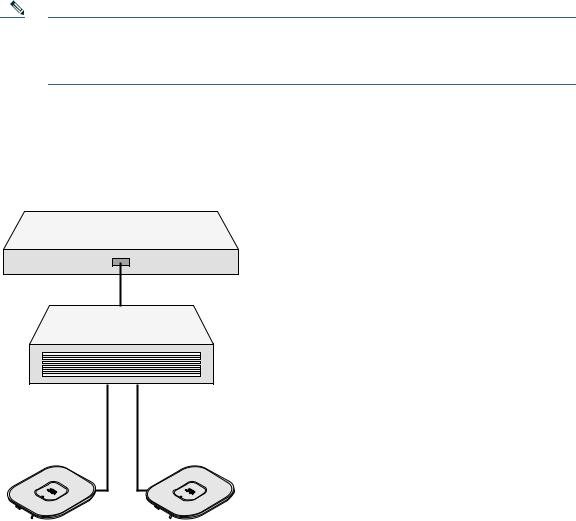
Performing a Pre-Installation Configuration
The following procedures ensure that your access point installation and initial operation go as expected. A pre-installation configuration is also known as priming the access point. This procedure is optional.
Note Performing a pre-installation configuration is an optional procedure. If your network controller is properly configured, you can install your access point in its final location and connect it to the network from there. See the “Deploying the Access Point on the Wireless Network” section on page 15 for details.
Pre-Installation Configuration Setup
The pre-installation configuration setup is shown in Figure 4.
Figure 4 Pre-Installation Configuration Setup
Controller
Layer 3 devices
Cisco Aironet access points
272488
To perform pre-installation configuration, perform the following steps:
12
 Loading…
Время на прочтение
9 мин
Количество просмотров 26K
Если вы серьезно занимаетесь Wi-Fi, то у вас точно есть своё лабораторное оборудование. Без него, на мой взгляд, не обойтись. Если вы собираетесь серьезно заниматься Wi-Fi, то рано или поздно, у вас возникнет необходимость обзавестись лабораторией. В этой статье я расскажу, как сделать это с минимальными затратами и для каких задач лаборатория может быть необходима, на реальных примерах.

Более 40% (по информации statista.com) корпоративного Wi-Fi занимает компания Cisco. Вероятно, вам потребуется именно это железо. Для начала нужно будет купить 2-3 точки доступа второй свежести. Например, AIR-CAP1702I-R-K9. Эти точки с поддержкой 802.11ac, но уже не такие дорогие, как свежие. Для каких-то задач подойдут даже AIR-CAP1602I-R-K9. Более старые брать не рекомендую. Зачастую, требуется поддержка точек свежим софтом, который нужно испытать, а свежий софт старые точки не поддерживает. Например, на 8.6 уже даже 1602 не заведутся. Если денег достаточно, то можно взять свежие точки с Mobility Express, типа 1852 или 2802. Тогда вам контроллер может и не понадобится первое время, но функционал реального контроллера все же будет побогаче, и позже он пригодится. Понять разницу можно, прочитав config guide для того и другого.
Где купить?
Купить можно у знакомого дистрибьютора с максимальной скидкой, либо по NFR цене, если вы работаете в интеграторе-партнере. Хотя руководство интегратора не всегда любит одобрять покупку чего-то “для себя”, даже по NFR цене. Если вам нужно найти железо по минимальной цене и за наличку, то ваш выбор Avito или ebay. Там бывают очень интересные предложения. Регуляторный домен точки доступа значения не имеет, так как на контроллере вы выставите нужный вам RU. При покупке у нас, в России, я советую записать все контакты продавца, сделать скрин объявления, так как малая вероятность того, что точки украли некие злые монтажники, она есть. Когда мы запускали один крупный объект, 10 из 200 точек доступа были украдены и найдены в недалеком ломбарде через Avito.
Итак, вы приобрели точки доступа. Если вы купили автономные точки, то перевести их в контроллерный (CAPWAP) режим (и наоборот) дело десяти минут, умеючи. Гуглится по запросу типа: Cisco 1702 lightweight to autonomous. Если у вас уже есть свободные точки, например, из ЗИП комплекта, вам повезло. Можно сразу переходить к следующему этапу – контроллеру.
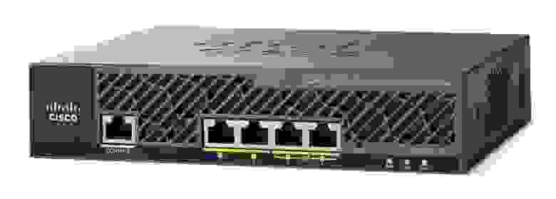
У Cisco есть 2 основных типа контроллеров, железный и виртуальный. Виртуальный работает только в режиме FlexConnect и это накладывает ряд ограничений, но во многих случаях его достаточно. У него есть одно неоспоримое преимущество, он условно-бесплатный. Точнее, полнофункциональная демо лицензия на почти 3 месяца активируется сразу после установки. 3 месяца это достаточный срок для испытаний. Если вам его нужно продлить, просто переустановите контроллер (сохранив конфиг) или еще проще, откатитесь на заранее созданный снимок виртуальной машины  опять же не забыв сохранить конфиг. Железный контроллер типа 2504 можно купить недорого в тех же местах где и точки. Сейчас их много на рынке.
Для установки виртуального контроллера вам потребуется:
1. Сервер где будет крутиться виртуальная машина. Для задач лабораторного контроллера подойдет любой ноутбук с 64 битным процессором, поддерживающим VT-x. Например, у меня это бывалый Thinkpad X220 на i5. Если у вас на работе в доступе есть могучий блейд с ESXi, конечно же уместно воспользоваться его мощностями. В общем, выбирайте из имеющегося.
2. ПО виртуализации типа VMware Workstation (немножко платный) или VirtualBox (даром отдают). Какой выбрать, решать вам. По моему опыту, OVA шаблон с виртуальным контроллером развернулся и заработал не на всех версиях VirtualBox. Заработал только на более старой, 5.0.16 и то не сразу. На 5.1.8 не заработал. На 5.2.6 не заводится конкретный OVA с 8.5 версией контроллера. На VMware Workstation завелся сразу и работал как часы, так что могу рекомендовать его.
3. OVA пакет с архивом всего необходимого, в том числе образа контролера. Официально качается на cisco.com при наличии доступа. Например, стабильный 8.0.152.0, доступен для скачивания просто так (если вы зарегистрированы на cisco.com). Если доступа к интересующему софту нет, но есть партнерство, то можно запросить, по дружбе. Если ни того ни другого, проявите смекалку.
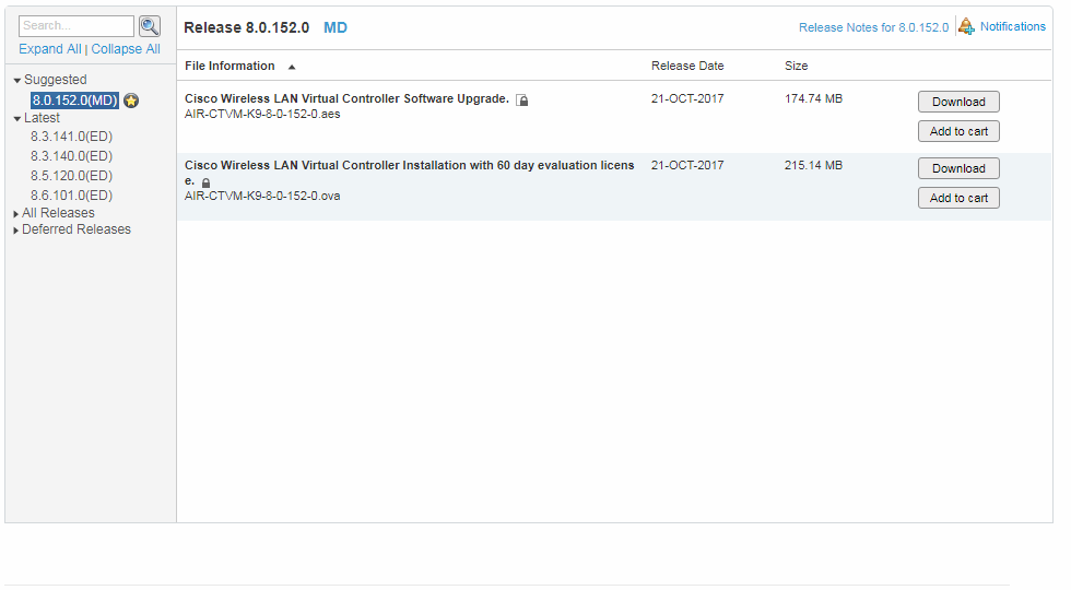
Не буду подробно с картинками рассказывать, как развернуть OVA, делается это как обычно. Открываете .ova, указываете где хранить машину и вперед…

Далее все пройдёт автоматически и скоро вы увидите, что пошла загрузка контроллера.

После загрузки вы увидите привычный диалог первой настройки контроллера, для которой вы конечно же заранее подготовились. На всякий случай в спойлере напомню параметры, которые потребуются. Значения, разумеется, ставить свои, а сервисный порт важно поместить в другую подсеть.
Параметры
System Name [Cisco_2c:4d:2f] (31 characters max): vWLC
Enter Administrative User Name (24 characters max): wlcadmin
Enter Administrative Password (3 to 24 characters): ********
Re-enter Administrative Password                 : ********
Service Interface IP Address Configuration [static][DHCP]: static 172.16.0.8
Management Interface IP Address: 10.8.8.2
Management Interface Netmask: 255.255.255.0
Management Interface Default Router: 10.8.8.1
Management Interface VLAN Identifier (0 = untagged): 0
Management Interface DHCP Server IP Address: 10.8.8.1
Enable HA [yes][NO]: NO
Virtual Gateway IP Address: 198.51.100.108
Mobility/RF Group Name: LAB
Network Name (SSID): TEST
Configure DHCP Bridging Mode [yes][NO]: no
Allow Static IP Addresses [YES][no]: no
Configure a RADIUS Server now? [YES][no]: no
Warning! The default WLAN security policy requires a RADIUS server.
Please see documentation for more details.
Enter Country Code list (enter 'help' for a list of countries) [RU]: RU
Enable 802.11b Network [YES][no]:
Enable 802.11a Network [YES][no]:
Enable Auto-RF [YES][no]: yes
Configure a NTP server now? [YES][no]: 10.8.8.1
Configure the system time now? [YES][no]: no
Warning! No AP will come up unless the time is set.
Please see documentation for more details.
Configuration correct? If yes, system will save it and reset. [yes][NO]: yes
Configuration saved!
Resetting system with new configuration...
После чего контроллер перезагрузится и заработает.
В консоли VMware будет доступ к консоли, через браузер по указанному Management Interface IP Address будет https доступ на WEB, что удобнее. Также можно по ssh.
Если веб доступа нет, вероятно, вы не к тому сетевому адаптеру привязали виртуальный.
Edit – Virtual Network Editor решит этот вопрос.
Далее все как обычно с контроллером, за исключением того, что точки доступа, чтобы заработать, должны быть переведены в режим FlexConnect. И не забудьте активировать лицензию, иначе вы будете долго гадать, почему же не устанавливается DTLS туннель!
Несколько примеров, для чего полезна лаборатория
Проверка нестандартных решений
Например, на одном заводе нужно было подключить ряд сетевых устройств на подвижном кране, через Wi-Fi. В качестве клиента использовалась точка доступа Cisco 1532E в WGB автономном режиме. Этот режим хорош тем, что позволяет гибко настраивать параметры роуминга, а устройства, подключенные через WGB видны по своим MAC в сети. Заказчик хотел убедиться в коротком времени роуминга в таком режиме.
Одну точку я перевел в автономный WGB режим и на длинном шнурке носил её в офисе, перемещаясь между висящими на потолке двумя контроллерными точками. Ноутбук был подключен к точке тем самым шнурком, поэтому в логах, по мере перемещения точки, появлялись подобные записи, которые однозначно позволяли судить о времени роуминга.
лог
*Mar 1 01:39:34.265: %DOT11-4-UPLINK_DOWN: Interface Dot11Radio1, parent lost: Too many retries

*Mar 1 01:39:34.265: E76D58EB-1 Uplink: Lost AP, Too many retries

*Mar 1 01:39:34.265: E76D597D-1 Uplink: Setting No. of retries in channel scan to 2

*Mar 1 01:39:34.265: E76D5985-1 Uplink: Wait for driver to stop

*Mar 1 01:39:34.265: E76D5FBB-1 Uplink: Enabling active scan

*Mar 1 01:39:34.265: E76D5FCA-1 Uplink: Not busy, scan all channels

*Mar 1 01:39:34.265: E76D5FD2-1 Uplink: Scanning

*Mar 1 01:39:34.313: E76E2161-1 Uplink: Rcvd response from 003a.7db3.c54f channel 161 538

*Mar 1 01:39:34.325: E76E231F-1 Uplink: An AP responded, try to assoc to the best one

*Mar 1 01:39:34.341: E76E82D7-1 Uplink: dot11_uplink_scan_done: rsnie_accept returns 0x0 key_mgmt 0xFAC02 encrypt_type 0x200

*Mar 1 01:39:34.341: E76E82ED-1 Uplink: ssid GMXM-C auth open

*Mar 1 01:39:34.341: E76E82F4-1 Uplink: try 003a.7db3.c54f, enc 200 key 4, priv 1, eap 0

*Mar 1 01:39:34.341: E76E82FE-1 Uplink: Authenticating

*Mar 1 01:39:34.341: E76E855C-1 Uplink: Associating

*Mar 1 01:39:34.341: E76E8DEB-1 Uplink: EAP authenticating

*Mar 1 01:39:34.353: %DOT11-4-UPLINK_ESTABLISHED: Interface Dot11Radio1, Associated To AP GMXM-1702i-1 003a.7db3.c54f [None WPAv2 PSK]

*Mar 1 01:39:34.353: E76EB2C7-1 Uplink: Done
В данном примере 353-265=88мс было потрачено на сканирование, выбор и переключение.
Разные варианты эксперимента показали время до 200мс, что всех устроило.
Может быть, для анализа времени роуминга правильнее бы было воспользоваться перехватчиком пакетов, слушать эфир с двух адаптеров и анализировать потом, но на тот момент это показалось достаточным.
Проверка свежего софта на стабильность
Есть полезное правило: лучшее враг хорошего. Если ваш софт актуальный, рекомендуемый как стабильный и вам достаточно его возможностей, менять его незачем. Если же вам нужны новые фичи, типа AVC на FlexConnect, то вероятно софт придется обновить. Если вы обслуживаете большую сеть, с сотнями или тысячами ТД, то риск того, что на свежем софте что-то пойдет не так, он есть. Для этого полезно иметь лабораторию, где можно на недельку запустить нужный софт и испытать его. Сколько стоит 1 час простоя сети на вашем предприятии? Сколько стоит набор для лабы? Сравните эти цены и решите сами.
Проверка времени простоя при применении некоторых команд
Если вы настраиваете живую сеть, это много интереснее, только нужно быть внимательнее и наперед знать результат ваших действий. Если простой живой сети создает проблемы, то лучше попробовать команды, которые требуют перезагрузки точек, заранее.
Например, есть такая удобная штука как RF Profile, в котором меняются data rate, рабочие MCS, параметры автоматического управления радиоэфиром, а также еще несколько полезных параметров типа RxSOP. Этот профайл вешается на группу точек, настраивая их разом. При этом нужно помнить о том, что если вы меняете существующий профайл, который уже в работе, то результата не последует. Изменения внесены не будут. Нужно прикрутить к группе точек другой профайл, точки перегрузятся, с его настройками, потом прикрутить исходный, который вы меняли, и тогда, повторно перегрузившись, точки заработают на новых настройках. Сколько времени это займет можно узнать, проведя эксперимент в офисе, чтобы потом согласовать с заказчиком небольшой перерыв связи.
Вразумить несговорчивых соседей по Wi-Fi
Допустим, ваша офисная сеть построена на UniFi. Соседние помещения арендует другая компания, а её админ, не зная о том, что в диапазоне 2.4ГГц всего три непересекающихся канала настроил соседнюю с вашей точку на 3й канал, да еще и 40МГц занял! Или даже это не админ сделал, а кривая прошивка сама выбрала 3й канал. При этом люди через этот третий канал торренты качают постоянно. Ваши коллеги стали жаловаться, что Wi-Fi работает хуже. Что делать? В идеале, перевести всё (оборудование) и всех (клиентов) на 5ГГц и забыть об этом страшном времени, когда ваш спектроанализатор показывал вот такие картинки
В реальной жизни пока это не удается. 2,4ГГц в РФ все еще популярен, спасибо производителям бюджетных китайских смартфонов.
Итак, перевести не получится, нужно общаться с соседним офисом. Скорее всего, если вы понятно объясните зачем им менять настройки, вопрос решится быстро. Если же никакие уговоры не помогают, или соседних офисов много и непонятно кто источник ваших беспокойств (хотя его можно обнаружить каким-нибудь бесплатным Wi-Fi Analyzer на вашем смартфоне), тогда можно применить тяжелую артиллерию. В разделе Monitor – Rogues, найти интересующую вас точку и в Update Status выбрать Contain.
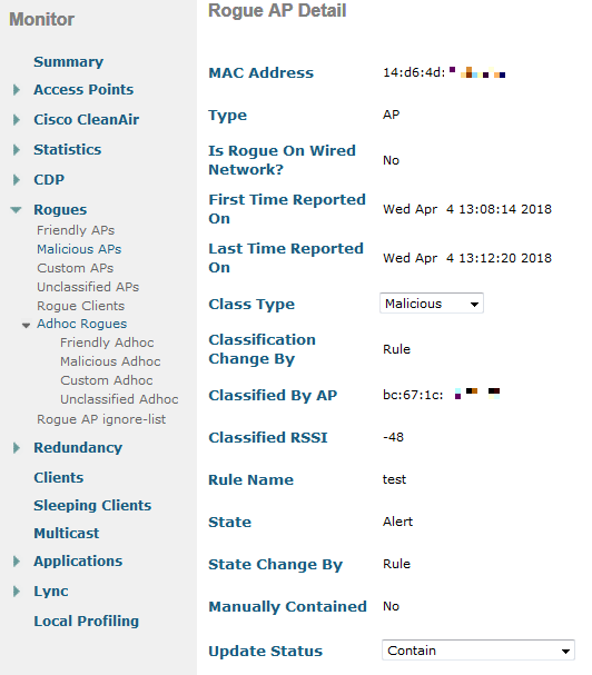
При этом контроллер заботливо вас предупредит о том, что это может быть нелегально. По сути, вы инициируете DoS атаку на сеть соседа, посылая со своих точек 802.11 de-authentication кадры от имени точки соседа для его клиентов. И всё, если вы слышите эту точку хотя-бы на уровне -70дБм и нажали кнопку Apply, выбрав при этом максимальное number of APs to contain the rogue, то все его клиенты просто перестают работать.

Люди не понимают, что происходит, так как физически отрубает и подключиться невозможно. Они пытаются менять настройки, это не помогает. Если вы при этом (через пару дней) заметили, что канал поменян, причем удачно, то статус Contain снимается и все довольны. Если нет, то решайте сами. На моём опыте, один раз через пару недель было обнаружено что люди поставили новую точку доступа, SSID остался прежний, но канал опять настроили криво.
Если кто знает, чем это легально может грозить в РФ, буду рад вашим комментариям. Так же любопытно, какие доказательства могли бы быть приняты. Обнаружить, что вас досят можно, но нужно обладать серьезной инфраструктурой, которая увидит, что это происходит и скажет об этом подобным образом: Warning: Our AP with Base Radio MAC f4:ea:67:00:01:08 is under attack (contained) by another AP on radio type 802.11b/g.
Ежели кто-то обладает такой инфраструктурой, крайне маловероятно, что он будет допускать подобные грубые ошибки в настройке. Если у вас есть софт типа Omnipeek для перехвата 802.11 кадров и адаптер, который может работать в promiscuous режиме, то он поможет обнаружить такую проблему. На любимом Kali Linux, вы и так знаете как ловить кадры и что делать. Таким образом, если вдруг в вашей сети люди резко перестали подключаться к Wi-Fi, совсем, ищите софт для перехвата, а перед этим проверьте, не мешаете ли вы соседям.
Если вы сомневались, просить ли у начальства (или у себя) выделить средства на покупку трех точек доступа чтобы собрать весьма полезную Wi-Fi лабораторию, я надеюсь ваши сомнения рассеяны.
More products and manuals for WLAN access points Cisco
| Models | Document Type |
|---|---|
|
MR26-HW |
Datasheet
4 pages |
|
WAP121-A-K9-NA |
Datasheet
6 pages |
|
WAP321-E-K9 |
Datasheet
7 pages |
|
AIR-CAP3502E-AK910 |
Datasheet
7 pages |
|
Aironet 350 Series |
Datasheet
10 pages |
|
AIR-CAP3502P-A-K9 |
Datasheet
6 pages |
|
AIR-CAP3502I-I-K9 |
Datasheet
7 pages |
|
AIR-AP1230B-A-K9 |
Datasheet
8 pages |
|
AIR-CAP3502I-EK910 |
Datasheet
6 pages |
|
AIR-LAP1310G-A-K9 |
Datasheet
14 pages |
|
WAP4410N |
Datasheet
5 pages |
|
AIR-AP1142-EK9-5PR |
Datasheet
5 pages |
|
WS-SVC-WISM-1-K9= |
Datasheet
12 pages |
|
AIR-AP1020-I-K9 |
Datasheet
9 pages |
|
AIR-AP1262N-E-K9 |
Datasheet
6 pages |
|
WRP400-G2 |
Datasheet
6 pages |
|
AIR-PI21AG-A-K9 |
Datasheet
8 pages |
|
AIR-AP1121G-J-K9 |
Datasheet
9 pages |
|
AIR-LAP1131G-E-K9 |
Datasheet
12 pages |
|
AIR-BR1310G-A-K9 |
Datasheet
4 pages |
